operation and installation - stiebel eltron usa · 2017-12-13 · 3.2 tank-mounted confi guration...
TRANSCRIPT
OPERATION AND INSTALLATION
RESIDENTIAL SOLAR PUMP STATION
» SE FLOWSTAR PUMP STATION

17 West St., W. Hatfi eld, MA 01088 | 800.582.8423 | 413.247.3380 | fax 413.247.3369 | [email protected] | www.stiebel-eltron-usa.com
Simply the Best
INSTALLATION INSTRUCTIONS SE FLOWSTAR PUMP STATION - 221337
Table of Contents
1 For your safety 1.1 About this manual 1.2 Designated use 1.3 Qualifi cation of the installer 1.4 Hand-over of the system (specialist) 1.5 General safety instructions 1.6 General instructions regarding solar fl uid 1.7 Frost damage
2 Description of the product
3 Assembly and installation 3.1 Wall-mounted confi guration 3.2 Tank-mounted confi guration 3.3 Wiring the pump
4 Commissioning 4.1 Flushing and fi lling the solar circuit 4.2 Preparation for fl ushing 4.3 Flushing the system 4.4 Filling the system 4.5 Setting the solar thermal system
5 Cleaning
6 Maintenance and decommissioning 6.1 Draining the solar system 6.2 Replacing the pump
7 Spare parts
8 Technical data and pressure drop characterisics
9 Commissioning log
! CAUTION: READ ALL INSTRUCTIONS BEFORE INSTALLING THIS PUMP STATION. ADDITIONAL
ITEMS WILL BE NEEDED TO MOUNT THIS ASSEMBLY.
1 For your safety
1.1 About the manual
This manual describes the function, installation, commissioning adn operation of a Stiebel Eltron SE Flowstar pump station. For other components of the solar installation, such as collectors, storage tanks, expansion tanks, controllers, and any other components, please refer to the specifi c manuals for those parts.
1.2 Designated use
The solar station is a pre-assembled fi tting assemblychecked for tightness and used for recirculating the solarfl uid in the solar circuit. The solar station must only beused in solar thermal systems as pumping station. It mustbe mounted in the return line of the solar circuit, taking intoconsideration the technical limit values indicated in thismanual. The station may only be assembled indoors. Thestation must be assembled and operated as described inthis manual!
1.3 Qualifi cation of the installer
Installation and commissioning of this equipment shouldbe done by qualifi ed installers [specialist] in accordancewith local, state and federal codes which may beapplicable.
The following must also be observed during installation and commissioning:
» Relevant regional and national regulations» Relevant accident prevention regulations» Instructions and safety instructions mentioned in this manual
1.4 Hand-over of the system
After installation and commissioning, the installer isresponsible for familiarizing the end user with the functionsof the system and the basic safety measures.

17 West St., W. Hatfi eld, MA 01088 | 800.582.8423 | 413.247.3380 | fax 413.247.3369 | [email protected] | www.stiebel-eltron-usa.com
Simply the Best
INSTALLATION INSTRUCTIONS SE FLOWSTAR PUMP STATION - 221337
» After commissioning, fi ll in the log on the last page of this manual.
» Hand the manual over to the end user. Instruct the end user to keep the manual in close proximity to the system.» Instruct the end user to have the solar station serviced and repaired by a specialist only. The controller settings must not be changed by the end user.» Explain to the end user the function of the system and of the safety devices. Point out to the end user that the shell must remain mounted during operation and that the check valve with temperature gauge and the ball valve in the fl owmeter must be open.
1.5 General safety instructions
Before installing and commissioning the product, you must read and observe the following safety instructions:
A. Danger of scalding due to escaping vapor If the system pressure is too high, hot solar fl uid will escape from the pressure relief valves and can result in scalding. Flush and fl l the system only if the collector temperatures are below 150F (70C).
Connect a discharge line to the safety assembly. Observe the instructions regarding the pressure relief valve.
B. Risk of burns
The valves, fi ttings and the pump may heat up to more than 212 °F (100 °C) during operation.
C. Personal injry and material damage caused by excess pressure
Closing the ball valves both in the return and supply line of the solar circuit, will disconnect the safety assembly from the heat exchanger. Heating the storage tank can result in the formation of high pressures, which may lead to material
damage and personal injury.
In operation, the ball valve with temperature gauge and the ball valve at the fl owmeter must always be open.
Close the ball valve only when service is required.
1.6 General instructions regarding solar fl uid
Propylene glycol is hazardous in the case of ingestion. It is an irritant when it comes into contact witht he eyes or skin.
Always wear chemically resistant protective gloves and safety glasses with side-shields when handling propylene glycol mixtures.
1.7 Frost damage
Observe the instructions and specifi cations of the antifreeze from the manufacturer.
It often happens that solar thermal systems cannot be completely drained after fl ushing. Thus, there is a risk of frost damage when fl ushing with water. Therefore, the solar thermal system should only be fl ushed and fi lled with the solar fl uid used later on.
Strictly follow the instructions of the antifreeze manufacturer for operating a solar thermal system. All components in the solar station are resistant to a percentage of propylene glycol of up to 50%.
Determine quantity according to system volume. See instructions of the collectors, storage tank and expansion tank.
2 Description of the product
This solar pump station is designed to be mounted in one of two ways. Both mounting options are discussed in the manual. It can be mounted either on a wall support and held by clip springs, or on a Stiebel Eltron solar storage tank using a tank mounting kit.
17 West St., W. Hatfi eld, MA 01088 | 800.582.8423 | 413.247.3380 | fax 413.247.3369 | [email protected] | www.stiebel-eltron-usa.com
Simply the Best
INSTALLATION INSTRUCTIONS SE FLOWSTAR PUMP STATION - 221337
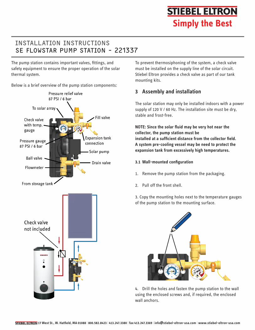
The pump station contains important valves, fi ttings, and safety equipment to ensure the proper operation of the solar thermal system.
Below is a brief overview of the pump station components:
To prevent thermosiphoning of the system, a check valve must be installed on the supply line of the solar circuit. Stiebel Eltron provides a check valve as part of our tank mounting kits.
3 Assembly and installation
The solar station may only be installed indoors with a power supply of 120 V / 60 Hz. The installation site must be dry,stable and frost-free.
NOTE: Since the solar fl uid may be very hot near the collector, the pump station must beinstalled at a suffi cient distance from the collector fi eld. A system pre-cooling vessel may be need to protect the expansion tank from excessively high temperatures.
3.1 Wall-mounted confi guration
1. Remove the pump station from the packaging.
2. Pull off the front shell.
3. Copy the mounting holes next to the temperature gauges of the pump station to the mounting surface.
4. Drill the holes and fasten the pump station to the wall using the enclosed screws and, if required, the enclosed wall anchors.

17 West St., W. Hatfi eld, MA 01088 | 800.582.8423 | 413.247.3380 | fax 413.247.3369 | [email protected] | www.stiebel-eltron-usa.com
Simply the Best
INSTALLATION INSTRUCTIONS SE FLOWSTAR PUMP STATION - 221337
8. Connect the expansion tank at the connection below the pressure gauge. Stiebel Eltron provides kits for quick connection of the expansion tank, but it is sold separately.
9. Adapt the initial pressure of the expansion tank to the system and connect the expansion tank. For more information regarding the installation of the expansion tank, please see the installation manual for that expansion tank.
10. Check all threaded connections and retighten them.
3.2 Tank-mounted confi guration
This section describes how to mount an SE Flowstar pump station onto an SBB tank using a low tank mounting kit. These components are sold separately.
1. Remove the pump station from the packaging.
2. Pull off the front shell.
3. Observe the lower connector of the pump station. Remove the ¾̋ NPT adapter, revealing a ¾̋ BSP threaded connection.
4. Inspect the threads of the tank to make sure they are clean and free of debris.
5. Connect the pump station to the system by means of the top and bottom connections. The bottom connection should be piped to the heat exchanger outlet of the storage tank. The top connection should be piped to return to the collector fi eld. It is recommended to ensure the seal of all threaded connections by using tefl on tape and pipe dope.
6. To prevent thermosiphoning, install a check valve in the supply line of the solar circuit.
7. Connect the discharge line to the pressure relief valve connection. Pipe this discharge line to a heat-resistant container.

17 West St., W. Hatfi eld, MA 01088 | 800.582.8423 | 413.247.3380 | fax 413.247.3369 | [email protected] | www.stiebel-eltron-usa.com
Simply the Best
INSTALLATION INSTRUCTIONS SE FLOWSTAR PUMP STATION - 221337
5. Remove the components from the tank mounting kit.
6. Apply tefl on tape & pipe dope to the 1̋ BSP threads on the lower HX assembly. Screw the assembly into the HX port and tighten it.
7. Apply tefl on tape & pipe dope to the 1̋ BSP threads on the upper HX assembly. Screw the assembly into the HX port and tighten it.
8. Attach the elbow piece of the lower HX assembly to the pump station. Save the gasket for the next step.
9. Attach the pump station to the lower HX connection. Ensure that the gasket is place between the connecting pieces.
10. Connect the discharge line to the pressure relief valve connection. Pipe this discharge line to a heat-resistant container.
11. Connect the expansion tank at the connection below the pressure gauge. Stiebel Eltron provides kits for quick connection of the expansion tank, but it is sold separately.
12. Adapt the initial pressure of the expansion tank to the system and connect the expansion tank. For more information regarding the installation of the expansion tank, please see the installation manual for that expansion tank.
13. Check all threaded connections and retighten them.

17 West St., W. Hatfi eld, MA 01088 | 800.582.8423 | 413.247.3380 | fax 413.247.3369 | [email protected] | www.stiebel-eltron-usa.com
Simply the Best
INSTALLATION INSTRUCTIONS SE FLOWSTAR PUMP STATION - 221337
3.3 Wiring the pump
1. Remove the screw from the pump housing. Connect an 18 gauge wire to the pump wiring block by threading it through the waterproof nut at the bottom of the pump housing. Be sure to connect the colored wires in the correct manner.
2. Close the pump housing, and reattach the front cover of the pump station.
3. Connect the pump wire to the solar controller. The solar controller should be installed and at this point, as it will be necessary to manually run the pump later in the installation process.
4 Commissioning
Before commissioning the pump station, read and observe the following safety instructions:
A. Risk of burns and scalding.
The valves and fi ttings may heat up to more than 212 (100C). During fl ushing, fi lling and venting, the solar fl uid can escape as vapor and result in scalding. Flush and fi ll the system only if the collector temperatures are below 150F (70C).
B. Propylene glycol safety. Propylene glycol is hazardous in the case of ingestion. It is an irritant when it comes into contact witht he eyes or skin.
Always wear chemically resistant protective gloves and safety glasses with side-shields when handling propylene glycol mixtures.
Observe the instructions and specifi cations of the antifreeze from the manufacturer.
C. Risk of frost.
It often happens that solar thermal systems cannot be completely drained after fl ushing. There is a risk of frost damage when fl ushing with water.
Therefore, the solar thermal system should only be fl ushed with water, immediately followed by the solar fl uid to fi ll the system.
Use a water and propylene glycol mixture with max. 50% propylene glycol as a solar fl uid, in order to avoid damaging gaskets and seals.
4.1 Flushing and fi lling the solar circuit.
The fi ll and drain connections required for fl ushing and fi lling are integrated into the solar station. In order to fl ush any dirt particles that may still be present out of the system, use only fl ush and fi ll stations equipped with suitable micro fi lters.
17 West St., W. Hatfi eld, MA 01088 | 800.582.8423 | 413.247.3380 | fax 413.247.3369 | [email protected] | www.stiebel-eltron-usa.com
Simply the Best
INSTALLATION INSTRUCTIONS SE FLOWSTAR PUMP STATION - 221337
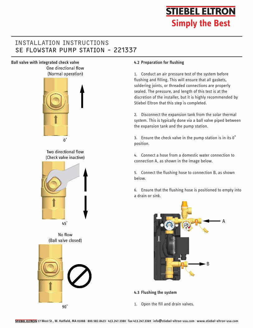
Ball valve with integrated check valveg 4.2 Preparation for fl ushing
1. Conduct an air pressure test of the system before fl ushing and fi lling. This will ensure that all gaskets, soldering joints, or threaded connections are properly sealed. The pressure, and length of this test is at the discretion of the installer, but it is highly recommended by Stiebel Eltron that this step is completed.
2. Disconnect the expansion tank from the solar thermal system. This is typically done via a ball valve piped between the expansion tank and the pump station.
3. Ensure the check valve in the pump station is in its 0 position.
4. Connect a hose from a domestic water connection to connection A, as shown in the image below.
5. Connect the fl ushing hose to connection B, as shown below.
6. Ensure that the fl ushing hose is positioned to empty into a drain or sink.
4.3 Flushing the system
1. Open the fi ll and drain valves.

17 West St., W. Hatfi eld, MA 01088 | 800.582.8423 | 413.247.3380 | fax 413.247.3369 | [email protected] | www.stiebel-eltron-usa.com
Simply the Best
INSTALLATION INSTRUCTIONS SE FLOWSTAR PUMP STATION - 221337
2. Open the domestic water connection to allow water to begin fl ushing through the system.
3. Leave the water running through the system and into the drain for a full 5 minutes after the fl ushing hose has begun purging water.
4. Close the fi ll and drain valves, as well as the domestic water connection.
5. Use the solar controller to manually circulate the fl uid. The process for doing this will depend on the controller you are using. Circulate the fl uid for 30 minutes.
4.4 Filling the system
1. Stop the manual operation of the pump and turn the pump to off on the controller.
2. Open the check valve in the pump station to its 45 position.
3. Close the ball valve in the fl ow meter.
4. Connect the charging pump hose to connection A, as shown above.
5. Make sure the fl ushing hose is still connected to the drain connection B.
6. Insert the fi lling hose (on the back end of the charging pump) into the solar fl uid.
7. Start the charging pump.
8. Open the fi ll valve.
9. Open the drain valve.
10. Observe the discharge of the fl ushing hose and make note of the color change of the fl uid to the propylene glycol mixture.
11. Close the drain valve.
12. Insert the fl ushing hose into the same bucket of propylene glycol mixture as the charging hose.
13. Open the ball valve that is isolating the expansion tank.
14. Open the drain valve to continue the circulation of solar fl uid through the system. This confi guration will allow any air in the system to be discharged via the bucket. Circulate the fl uid in this manner for 15 minutes.
15. Close the drain valve again. The system will now begin building pressure. Observe the pressure on the pump station gauge until it reaches the intended cold system pressure.
16. Close the fi ll valve and turn off the charging pump.
17. Open the ball valve in the fl ow meter.
18. Set the check valve to the 0 operating position.
19. Manually run the pump via the pump station to ensure that the system is working propery.
20. Air may have accumulated at the solar collectors. It is important to bleed off any air from them to ensure that they are performing uniformly.
4.5 Setting the solar system
Observe the specifi cations of the manufacturer of the collectors for the correct adjustment of the fl ow rate. For Stiebel Eltron SOL 27 Premium collectors, the recommended fl ow rate is 0.75 gpm/collector.
Part: # of Collectors in Array:1 2 3 4
Flow Rate (gpm):SOL 27 Premium collector 0.75 1.5 2.25 3.0
1. Set the desired max. fl ow rate voa the rotation speed of the solar pump. The controller will set the speed accordingly.

17 West St., W. Hatfi eld, MA 01088 | 800.582.8423 | 413.247.3380 | fax 413.247.3369 | [email protected] | www.stiebel-eltron-usa.com
Simply the Best
INSTALLATION INSTRUCTIONS SE FLOWSTAR PUMP STATION - 221337
Before decommissioning, wait until the solar fl uid has cooled down below 122F (50C).
6.1 Draining the solar installation
Complete draining allows components in the pump station to be replaced.
1. Disconnect the controller from the power supply and secure it against being switched on again.
2. Open the check valve to the 45 position.
3. Connect a heat-resistant hose to the drain valve. Make sure that the solar fl uid is collected in a heat-resistant container.
4. Open the drain valve.
5. To accelerate the draining of the solar circuit, open the bleeding device at the collectors.
6. If discarding the solar fl uid, dispose of it observing any local regulations.
6.2 Replacing the pump
1. After performing the draining process as in 6.1, disconnect the pipe joint between the pump station and the storage tank.
2. Dismount the fl owmeter connection to the pump.
3. Dismount the pump connection from the upper assembly.
4. Install the new pump, making sure to include new gaskets.
5. Mount the fl owmeter.
6. Connect the pump station to its original connections. Repeat the commissioning process as described in section 4.7 Spare parts
2. Observe the fl ow via the fl owmeter.
2. Re-mount the front shell on the solar station.
3. Set the controller to automatic mode.
5 Cleaning
Clean the pump station only from the outside with a damp cloth. Never use scouring or sand-containing cleaning agents.
6 Maintenance and decommissioning
Before maintaining and decommissioning the system, read and observe the following safety instructions.
A. Risk of electric shock
Disconnect all electrical devices in the solar circuit from the power supply before carrying out maintenance work or decimmissioning.
Ensure that the electrical devices cannot be switched on again.B. Risk of burns and scalding.
The valves and fi ttings may heat up to more than 212 (100C).

17 West St., W. Hatfi eld, MA 01088 | 800.582.8423 | 413.247.3380 | fax 413.247.3369 | [email protected] | www.stiebel-eltron-usa.com
Simply the Best
INSTALLATION INSTRUCTIONS SE FLOWSTAR PUMP STATION - 221337
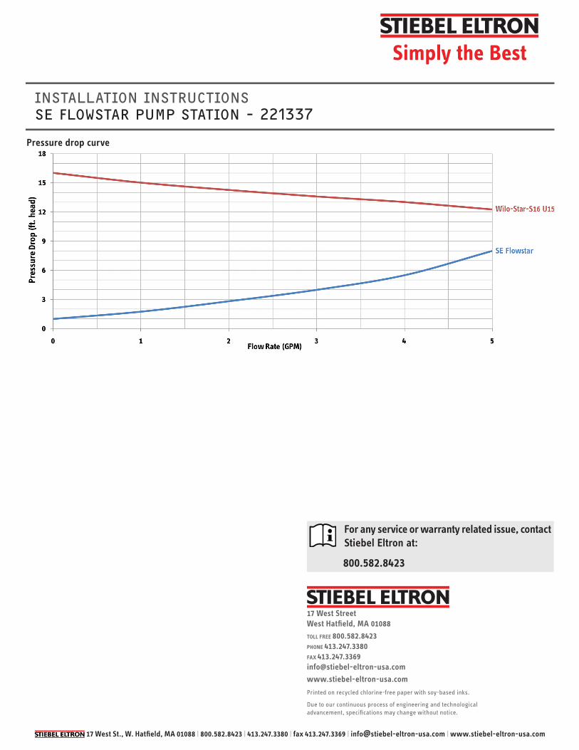
8 Technical data and pressure drop curve
Technical dataSE Flowstar Pump Station
DimensionsHeight 14.9 in. / 379 mmWidth 8.94 in. / 227 mmDepth 5.9 in. / 150 mmUpper & lower connections ¾̋ Male NPT or ¾̋ Female BSPExp. tank connection ¾̋ Male BSPPRV connection ¾̋ Female BSPTemperature & PressureMax. pressure 145 PSI / 10 barMax. temp. 248F / 120CMax. short term temp. 320F / 160C for < 15 min.Max. propylene glycol % 50%EquipmentPressure relief valve 87 psi / 6 barPressure gauge 0-87 psi / 0-6 barCheck valve 7.9 in. head / 200 mmWCFlowmeter 0.1-4 gpmMaterialValves & fi ttings BrassGaskets EPDMCheck valves BrassInsulation EPP, λ=0.043 W/(m•K)
Dimensions
Below is a diagram of the spare parts that can be ordered from Stiebel Eltron. If you need to order a replacement part, please contact Stiebel Eltron and use the part numbers below as a reference.
17 West St., W. Hatfi eld, MA 01088 | 800.582.8423 | 413.247.3380 | fax 413.247.3369 | [email protected] | www.stiebel-eltron-usa.com
Simply the Best
INSTALLATION INSTRUCTIONS SE FLOWSTAR PUMP STATION - 221337
Pressure drop curve
For any service or warranty related issue, contact Stiebel Eltron at:
800.582.8423
17 West StreetWest Hatfi eld, MA 01088TOLL FREE 800.582.8423PHONE 413.247.3380FAX 413.247.3369info@stiebel-eltron-usa.comwww.stiebel-eltron-usa.com
Printed on recycled chlorine-free paper with soy-based inks.
Due to our continuous process of engineering and technological advancement, specifi cations may change without notice.

This page intentionally left blank

17 West St., W. Hatfi eld, MA 01088 | 800.582.8423 | 413.247.3380 | fax 413.247.3369 | [email protected] | www.stiebel-eltron-usa.com
Simply the Best
COMMISSIONING LOG SE FLOWSTAR PUMP STATION
The installer should fi ll out this sheet at the end of the installation, and leave it at the installation site.
Site:System operator: Installation site:
Collectors:Collectors (number / type): Collector surface area:
System specifi cations:System height: Pipe run length: Ventilation: Solar fl uid (type / concentration): Max. fl ow rate: Pump station: Pump setting (low/med/high): System pressure (cold): System pressure (hot): Expansion tank:
Checklist:Mark for condition (checked, closed, open, etc.)Pressure relief valve: Check valves: Ball valves:
Serial numbers:Pump station: Controller: Software version:
Installation company:
Signature: Date: