operational amplifier - olsjdt | our lady and st. john … · web viewto build and test operational...
TRANSCRIPT

UNIT 35 BTEC National Engineering
Principles and Applications of Electronic Devices and Circuits
Assignment:-To Build and Test Operational Amplifier Based Analogue Circuits
This assignment will satisfy part of the criteria for P4
P4 Build and test two different types of analogue circuit using operational amplifiers
Activity Tasks
1. You are going to build and test a Microphone circuit that will amplify a voice and plot the resultant output waveform on an oscilloscope
2. You will build and test a 741 analogue Operational Amplifier circuit that uses the microphone circuit as an input.
This assignment uses resources that can be found on
http://www.doctronics.co.uk/scope.htm - circuit 3 Accessed March 2013
Our Lady & St John Catholic CollegeName_________________________ Date _____________________
UNIT 35 BTEC National Engineering
Principles and Applications of Electronic Devices and Circuits
Microphone Input
This part of the Practical is an investigation of microphones, audio signals and amplifiers, intended to develop your prototype board skills and giving you experience of using the oscilloscope to monitor signals in a simple circuit.
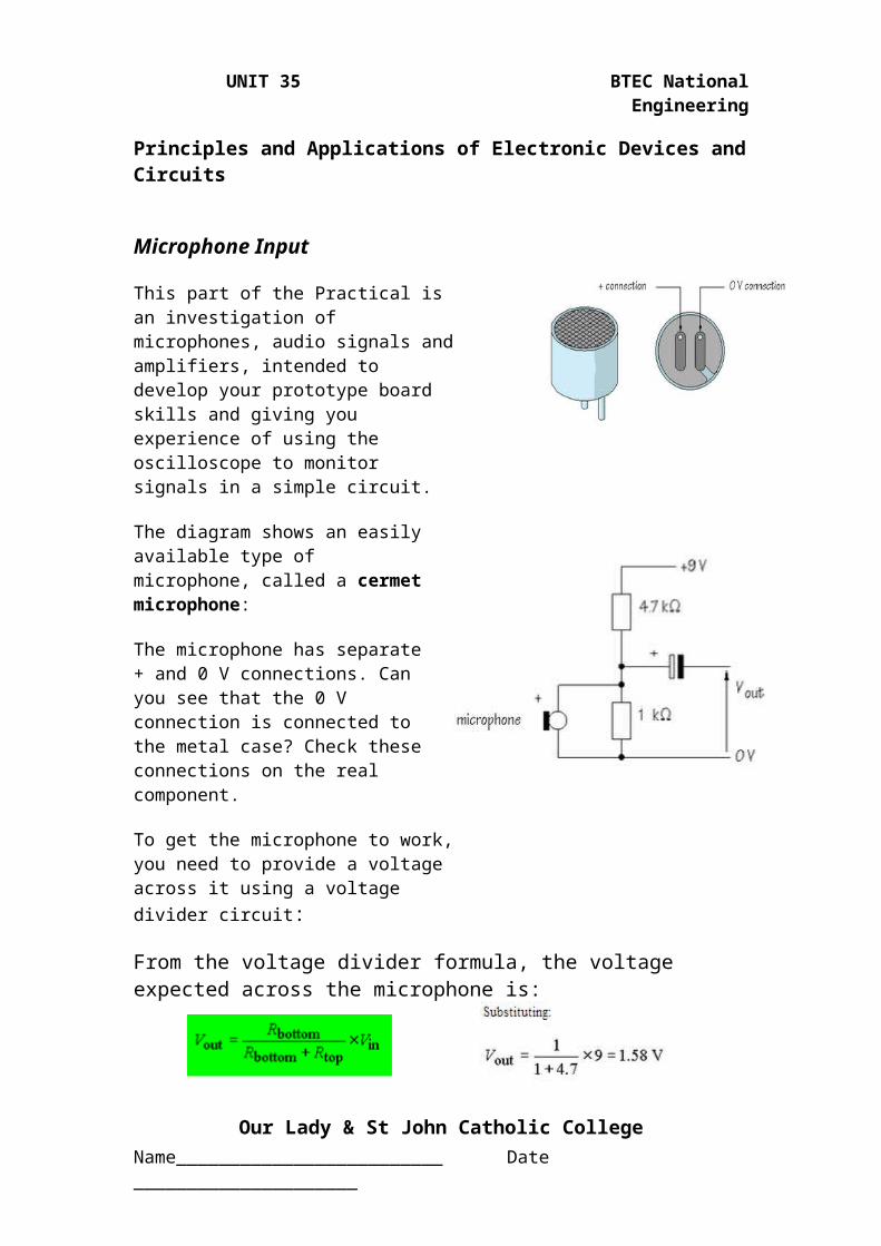
The diagram shows an easily available type of microphone, called a cermet microphone:
The microphone has separate + and 0 V connections. Can you see that the 0 V connection is connected to the metal case? Check these connections on the real component.
To get the microphone to work, you need to provide a voltage across it using a voltage divider circuit:
From the voltage divider formula, the voltage expected across the microphone is:
Build the Voltage Divider Circuit on a breadboard. Use a Voltmeter to :-
Measure the voltage between the resistors.
Voltage = ________________
How closely does the measured value agree with the calculated one?
Voltage Difference = _______
Our Lady & St John Catholic CollegeName_________________________ Date _____________________

UNIT 35 BTEC National Engineering
Principles and Applications of Electronic Devices and Circuits
Possible Reasons for a Difference in Results.
Small differences in expected results can arise if you have not provided the power supply voltage to exactly 9 V and also because the resistors may not have precisely their marked values. Remember, resistors are manufactured to a tolerance, usually ±5%, so that their values are not exact.
Addition of the Microphone
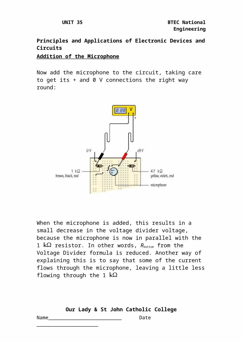
Now add the microphone to the circuit, taking care to get its + and 0 V connections the right way round:
When the microphone is added, this results in a small decrease in the voltage divider voltage, because the microphone is now in parallel with the 1 resistor. In other words, Rbottom from the Voltage Divider formula is reduced. Another way of explaining this is to say that some of the current flows through the microphone, leaving a little less flowing through the 1
Our Lady & St John Catholic CollegeName_________________________ Date _____________________
UNIT 35 BTEC National Engineering
Principles and Applications of Electronic Devices and Circuits
Adding the 4.7 uF Capacitor
Check the polarity of a 4.7 µF or 10 µF capacitor (longer leg positive, stripe negative) and connect this as indicated below
Now in this circuit, the capacitor blocks DC voltages, but allows AC voltages, including audio signal, to pass
Setting up the Oscilloscope to Trace the Microphone Signal
The arrangement outlined below is a very convenient way of setting up an oscilloscope to make measurements from the prototype circuit:
Once the crocodile clip corresponding to the black lead has been connected to 0 V, it can be ignored. This leaves the test probe which can be connected to any point in the circuit to monitor the signals present.
Connect the test probe to the prototype circuit as indicated. Increase the sensitivity of the VOLTS/DIV control by rotating it clockwise until you can see changes on the oscilloscope screen when you talk into the microphone. Adjust TIME/DIV until the shape of the signals is clear.
Our Lady & St John Catholic CollegeName_________________________ Date _____________________
Oscilloscope

UNIT 35 BTEC National Engineering
Principles and Applications of Electronic Devices and Circuits
Results of Oscilloscope Test for the Microphone
In the space below, make a drawing to represent the V/t graph of an audio signal:
How large is your signal in mV, peak-to-peak amplitude?
What sort of signal is produced if you clap your hands within range of the microphone?
Our Lady & St John Catholic CollegeName_________________________ Date _____________________
UNIT 35 BTEC National Engineering
Principles and Applications of Electronic Devices and Circuits
This concludes the measurement of the microphone circuit using an oscilloscope
Our Lady & St John Catholic CollegeName_________________________ Date _____________________
UNIT 35 BTEC National Engineering
Principles and Applications of Electronic Devices and Circuits
Operational Amplifier
When you talk into the microphone, the signals you get are small. To make them bigger, you need an amplifier. One possible circuit is shown below. This uses a 741, one of a large family of integrated circuits called operational amplifiers, or op-amps
The internal circuit of a 741 is quite complicated but it is easy to use the device simply as an amplifying subsystem.
It is cheap and easily available. As you can see, the 741 is manufactured in a small plastic package, with 8 connecting pins. These are in a dual in line, or DIL arrangement.
With the index mark at the top, pin 1 is on the left and pins are numbered down the left hand side and back up on the right.
Often, there is an additional circular mark next to pin 1. This numbering convention is followed on other integrated circuits, whether there are 8, 14, 16, or more pins.
Our Lady & St John Catholic CollegeName_________________________ Date _____________________
Figure 1:- 741 Op Amp schematic and 8 pin Integrated package
UNIT 35 BTEC National Engineering
Principles and Applications of Electronic Devices and Circuits
Build the Operational Amplifier Circuit
Place the 741 across the central gap in the prototype board. Check that pin 1 is correctly located. Now complete the circuit, as follows:
Dual Power Supply
Our Lady & St John Catholic CollegeName_________________________ Date _____________________

UNIT 35 BTEC National Engineering
Principles and Applications of Electronic Devices and CircuitsThe +9 V, 0 V, -9 V dual power supply required can be made using two PP3 batteries, connected to the prototype board as shown:-
Our Lady & St John Catholic CollegeName_________________________ Date _____________________
UNIT 35 BTEC National Engineering
Principles and Applications of Electronic Devices and Circuits
Testing the Operational Amplifier
Check back with your prototype board and make sure that you have linked the SENSOR subsystem to the AMPLIFIER with a wire link.
Monitor the final output of the system using the oscilloscope. The signals should have increased in magnitude.
Gain Calculation
The voltage gain of the amplifier is given by:
The way in which this particular op-amp circuit works allows you to choose the voltage gain according to:
The minus sign appears because this is an inverting amplifier circuit, that is, the output waveform has the same shape as the input waveform, but is turned upside down, or inverted, compared with the input waveform. What matters here is that the amplitude of the waveform is increased.
Our Lady & St John Catholic CollegeName_________________________ Date _____________________

UNIT 35 BTEC National Engineering
Principles and Applications of Electronic Devices and Circuits
The voltage gain of the circuit is calculated from:
Vout is inverted and the amplitude of the signal is increased by 47 times.
Vout after the amplifier should be 47 times larger than the signal from the microphone subsystem
Do your observations using the oscilloscope confirm these changes?
Produce a summary of your observations. Include a measurement of the average peak to peak amplitude of the amplified signal if you clap your hands within range of the microphone?
Our Lady & St John Catholic CollegeName_________________________ Date _____________________

UNIT 35 BTEC National Engineering
Principles and Applications of Electronic Devices and Circuits
Use this page to attach photographic evidence of your build and testing of the circuits on breadboard. Include photographs of
measuring the circuit output using the oscilloscope
This concludes the investigation into the operational amplifier.
Our Lady & St John Catholic CollegeName_________________________ Date _____________________