overhead wiring and signalling structures standard · all mtm standards are periodically reviewed...
TRANSCRIPT

Engineering Standard
L1-CHE-STD-058 OVERHEAD WIRING AND SIGNALLING STRUCTURES STANDARD Version: 2

ENGINEERING STANDARD OVERHEAD WIRING AND SIGNALLING
STRUCTURES STANDARD
L1-CHE-STD-058 Version: 2 Effective from: 17th July 2018
Approving Manager: Chief Engineer Approval Date: 17/07/2018 Next Review Date: 17/07/2021 PRINTOUT MAY NOT BE UP-TO-DATE; REFER TO METRO INTRANET FOR THE LATEST VERSION Page 2 of 18
Approval
Amendment Record
Approval Date Version Description
11/04/2018 1 Initial release by MTM. Supersedes L1-CHE-INS-037 Overhead Wiring and Signalling Structures. Refer to MoC no. 4126.
17/07/2018 2 Standard updated to reflect release of L1-CHE-STD-025 Transit Space Clearance Standard. Refer to MOC #44753 for details.

ENGINEERING STANDARD OVERHEAD WIRING AND SIGNALLING
STRUCTURES STANDARD
L1-CHE-STD-058 Version: 2 Effective from: 17th July 2018
Approving Manager: Chief Engineer Approval Date: 17/07/2018 Next Review Date: 17/07/2021 PRINTOUT MAY NOT BE UP-TO-DATE; REFER TO METRO INTRANET FOR THE LATEST VERSION Page 3 of 18
PREFACE
Metro Trains Melbourne (MTM) Standards have been developed to ensure common approaches are employed when designing, constructing or testing any part of the Melbourne Metropolitan Rail Network. It is important to understand that Standards are living documents which take into account learnings to achieve best practice.
All MTM Standards are periodically reviewed and new versions published which incorporate learnings and Technical Notes (TNs). TNs are issued between editions which correct any errors or ambiguities contained in an MTM Standard. Standards may also be withdrawn and replaced. As Standards are uncontrolled once printed, it is imperative to check the currency of the Standard on the MTM Intranet or MTM External Document Portal.
In the event of conflicts or discrepancies between Documents, refer to the order of precedence as defined in ‘Chief Engineer’s Guideline Engineering Standards Listing’ (L1-CHE-GDL-005).
Note: Any clarification described in a TN shall take precedence over the impacted clause or clauses in the associated MTM Standard.
In the event a clause within a Standard is not achievable a waiver must be raised in accordance with ‘Engineering Waiver Procedure’ - L1-CHE-PRO-001.
Note: MTM does not have the authority to grant waivers to any Standards which relate to Government Regulations or Legislation, e.g. Disability Discrimination Act.
Application of this Standard This Standard is applicable from the approval date.

ENGINEERING STANDARD OVERHEAD WIRING AND SIGNALLING
STRUCTURES STANDARD
L1-CHE-STD-058 Version: 2 Effective from: 17th July 2018
Approving Manager: Chief Engineer Approval Date: 17/07/2018 Next Review Date: 17/07/2021 PRINTOUT MAY NOT BE UP-TO-DATE; REFER TO METRO INTRANET FOR THE LATEST VERSION Page 4 of 18
Table of Contents 1 Purpose ........................................................................................................................... 5
2 Scope ............................................................................................................................... 5
3 Abbreviations .................................................................................................................. 5
4 Definitions ....................................................................................................................... 6
5 References & Legislations ............................................................................................. 6
General ............................................................................................................................. 6
MTM References .............................................................................................................. 7
Industry References .......................................................................................................... 7 Australian References and Legislation ............................................................................. 8
6 Related Documents ........................................................................................................ 8
7 Safety & Environmental .................................................................................................. 8
8 Design Requirements ................................................................................................... 10
Structure Importance Level and Design Life .................................................................. 10
General Requirements .................................................................................................... 10
Detailing Requirements .................................................................................................. 11
9 Design Loads .................................................................................................................. 13
Design Loads – Overhead Wiring Structures ................................................................. 13
Design Loads – Signalling Structures ............................................................................. 15
10 Appendix A – Documentation Requirements .............................................................. 17
General ........................................................................................................................... 17
Drawings ......................................................................................................................... 17 Design Report ................................................................................................................. 18
List of Tables Table 1 – Permanent Effects Deflection Limits for Overhead Wiring Structures ............................ 14
Table 2 - Load Cases for Overhead Wiring Structures and Signalling Structures .......................... 14
Table 3 - ULS Load Combinations for Overhead Wiring Structures ............................................... 15
Table 4 - SLS Load Combinations for Overhead Wiring Structures ............................................... 15
Table 5 - ULS Load Combinations for Signalling Structures .......................................................... 16
Table 6 - SLS Load Combinations for Signalling Structures .......................................................... 16
Table 7 - Deflection Limits ............................................................................................................. 16
List of Figures Figure 1: Typical locknut arrangement for hold down bolts ............................................................ 12

ENGINEERING STANDARD OVERHEAD WIRING AND SIGNALLING
STRUCTURES STANDARD
L1-CHE-STD-058 Version: 2 Effective from: 17th July 2018
Approving Manager: Chief Engineer Approval Date: 17/07/2018 Next Review Date: 17/07/2021 PRINTOUT MAY NOT BE UP-TO-DATE; REFER TO METRO INTRANET FOR THE LATEST VERSION Page 5 of 18
1 Purpose This Standard specifies the design and functional requirements for overhead wiring
structures and signalling structures on the Metro Trains Melbourne (MTM) network.
2 Scope This Standard sets out design requirements for structures supporting overhead wiring or
signalling equipment. It is applicable for new structures and upgrades to existing structures.
The Standard is applicable to the design of footings, masts, portals and other non-operable structural elements undertaken using standard structural materials (refer to Sections 7.8, 8.3.4 and 8.3.5). It may be used as a reference in the design of new operable structures (such as tilt masts) and proprietary structures or components, however is not intended to provide comprehensive requirements for these structures. These requirements shall be established as part of their Type Approval.
Note: This Standard does not provide requirements for inspection and maintenance. These are covered by the appropriate Technical Maintenance Plans.
This Standard does not address the location or placement of structures.
This Standard is mandatory for all such works proposed in the MTM Infrastructure Lease.
3 Abbreviations AASHTO American Association of State Highway and Transportation Officials
AT Auto-tensioned
DMS Drawing Management System (managed by PTV)
MPA Mid-point Anchor
MTM Metro Trains Melbourne
PTV Public Transport Victoria
RSNL Rail Safety National Law
SFAIRP So Far As Is Reasonably Practicable
SLS Serviceability Limit State
SSA Self-Supporting Anchor
STC Single Track Cantilever
TTC Twin Track Cantilever
UC Universal Column
ULS Ultimate Limit State

ENGINEERING STANDARD OVERHEAD WIRING AND SIGNALLING
STRUCTURES STANDARD
L1-CHE-STD-058 Version: 2 Effective from: 17th July 2018
Approving Manager: Chief Engineer Approval Date: 17/07/2018 Next Review Date: 17/07/2021 PRINTOUT MAY NOT BE UP-TO-DATE; REFER TO METRO INTRANET FOR THE LATEST VERSION Page 6 of 18
4 Definitions Auxiliary feeder Conductor(s) both physically and electrically parallel to the catenary to
provide voltage and/or current support.
Catenary wire The conductor wire from which the contact wire is suspended.
Contact wire Solid conductor used to supply electric energy to rail vehicles through current collection equipment.
Infrastructure Lease
The Land and Infrastructure as defined in the Train Infrastructure Module of the MR4 Franchise Agreement.
Mid-point anchor A point along an AT tension length where the catenary is restrained in order to prohibit the tendency of the overhead system to migrate to one end of the tension length over time.
MTM Chief Engineer
The term shall be taken to include a delegate of the MTM Chief Engineer.
Overhead wiring structure
A structure providing support to overhead wiring equipment.
Radial Load Horizontal load comprising of static forces caused by a change in the direction of a wire at a support or registration point.
Self-Supporting Anchor
Anchor mast without a back-guy.
Signalling Structure
A structure providing support and access to signalling equipment.
Shall Is used as the descriptive word to express a requirement that is mandatory to achieve conformance to the standard.
Should Is used as the descriptive word to express a requirement that is recommended in order to achieve compliance. ‘Should’ can also be used if a requirement is desirable but not a mandatory requirement.
Upgrade Alteration of wiring registrations or other equipment that increases load on an existing structure, or change to the form of the structure. Excludes repairs and like-for-like component renewals.
5 References & Legislations
General 5.1.1 Overhead wiring structures and signalling structures shall be designed in
accordance with this Standard, other relevant MTM and Australian Standards and MTM Requirements documents.
5.1.2 Where a conflict arises between Standards or clarification as to the applicability of a Standard or a part of a Standard is required, the matter shall be referred to the MTM Chief Engineer for determination.

ENGINEERING STANDARD OVERHEAD WIRING AND SIGNALLING
STRUCTURES STANDARD
L1-CHE-STD-058 Version: 2 Effective from: 17th July 2018
Approving Manager: Chief Engineer Approval Date: 17/07/2018 Next Review Date: 17/07/2021 PRINTOUT MAY NOT BE UP-TO-DATE; REFER TO METRO INTRANET FOR THE LATEST VERSION Page 7 of 18
MTM References
Document Number Title
L0-HMR-MAN-001 Business Rules Manual for the Contracting Rail Safety Worker
L0-SQE-MAN-002 Safety Management System Manual
L0-SQE-PLA-005 Environmental Management Plan
L0-SQE-PRO-014 Safety & Environmental Requirements for Third Parties Working on MTM Premises.
L0-SQE-PRO-031 Enterprise Risk Management Procedure
L1-CHE-POL-001 Engineering Drawings Management Policy (IFC/As Builts)
L1-CHE-PRO-004 Type Approval Procedure
L1-CHE-PRO-001 Standard Waiver Procedure
L1-CHE-STD-010 Electrical Networks Standard – Railway Bridges Electrical Protection and Bonding
L1-CHE-STD-011 1500VDC Overhead Wiring System
L1-CHE-STD-016 Traction Bonding for Signalling and Traction Return Current
L1-CHE-STD-025 Transit Space Clearances
L1-CHE-STD-068 Standard Rail Signalling Naming & Symbol Conventions
L1-NAM-PRO-002 Design and Technical Review Procedure
Industry References
Document Number Title
STD_G0071 Number Plate Signal Mast
(Standard Drawing available in DMS)
STD_G0148 Signal Gantries for Stand Alone Boxes Details
(Standard Drawing available in DMS)
D5403 Overhead Structure Label General Arrangement
(Standard Drawing available in DMS)
n/a PTV Infrastructure Drafting Standards
n/a AASHTO Standard Specifications for Structural Supports for Highway Signs, Luminaires, and Traffic Signals, Fifth Edition (2009)
n/a VicRoads Supplement to the Austroads Guide to Road Design – Part 6 – Roadside Design, Safety & Barriers

ENGINEERING STANDARD OVERHEAD WIRING AND SIGNALLING
STRUCTURES STANDARD
L1-CHE-STD-058 Version: 2 Effective from: 17th July 2018
Approving Manager: Chief Engineer Approval Date: 17/07/2018 Next Review Date: 17/07/2021 PRINTOUT MAY NOT BE UP-TO-DATE; REFER TO METRO INTRANET FOR THE LATEST VERSION Page 8 of 18
Australian References and Legislation
Document Number Title
AS 1100 Technical Drawing
AS/NZS 1112.4 ISO metric hexagon nuts Chamfered thin nuts - Product grades A and B
AS 1170 Structural design actions
AS/NZS 1214 Hot-dip galvanized coatings on threaded fasteners
AS 1657 Fixed Platforms, Walkways, Stairways and Ladders
AS/NZS 1891 Industrial fall-arrest systems and devices - Harnesses and ancillary equipment
AS 2159 Piling – Design and installation
AS 4100 Steel structures
AS 4291.2
Mechanical properties of fasteners made of carbon steel and alloy steel - Nuts with specified property classes - Coarse thread and fine pitch thread
AS/NZS 4676 Structural design requirements for utility services poles
AS/NZS 4680 Hot-dip galvanised (zinc) coatings on fabricated ferrous articles
AS 5100 Bridge design
AS/NZS 5532 Manufacturing requirements for single-point anchor device used for harness-based work at height
n/a Rail Safety National Law Application Act 2013 (Vic)
S.R. No. 54/2007 Victorian OHS Regulations 2007
6 Related Documents MCMP 000000-01 Structures & Facilities Technical Maintenance Plan
7 Safety & Environmental The general requirements in relation to safety are included in MTM’s Safety Management
System Manual (L0-SQE-MAN-002).
The design and construction of overhead wiring structures and signalling structures shall comply with the L0-SQE-PLA-005 – MTM Environmental Management Plan and L0-SQE-PRO-014 Safety & Environmental Requirements for Third Parties Working on MTM Premises.
All rail safety workers shall comply with the Business Rules Manual for the Contracting Rail Safety Worker (L0-HMR-MAN-001) and have the appropriate competencies to undertake their role.

ENGINEERING STANDARD OVERHEAD WIRING AND SIGNALLING
STRUCTURES STANDARD
L1-CHE-STD-058 Version: 2 Effective from: 17th July 2018
Approving Manager: Chief Engineer Approval Date: 17/07/2018 Next Review Date: 17/07/2021 PRINTOUT MAY NOT BE UP-TO-DATE; REFER TO METRO INTRANET FOR THE LATEST VERSION Page 9 of 18
Under RSNL (s46) MTM is required to:
a) eliminate risks to safety so far as is reasonably practicable; and
b) if it is not reasonably practicable to eliminate risks to safety, to minimise those risks so far as is reasonably practicable.
Under RSNL (s47), reasonably practicable means that which is, or was at a particular time, reasonably able to be done to ensure safety, taking into account and weighing up all relevant matters including:
a) the likelihood of the hazard or the risk concerned occurring; and
b) the degree of harm that might result from the hazard or the risk; and
c) what the person concerned knows, or ought reasonably to know, about-
i. the hazard or risk, and ways of eliminating or minimising the risk; and
ii. the availability and suitability of ways to eliminate or minimise the risk; and
d) after assessing the extent of the risk and the available ways of eliminating or minimising the risk, the cost associated with available ways of eliminating or minimising the risk, including whether the cost is grossly disproportionate to the risk.
Under RSNL (s50), rail safety is a shared responsibility of:
a) Rail transport operators; and
b) Rail safety workers; and
c) Other persons who:
i. Design, commission, construct, manufacture, supply, install, erect, maintain, repair, modify or decommission rail infrastructure or rolling stock; or
ii. Supply rail infrastructure operations or rolling stock operations to rail operators; or
iii. In relation to the transport of freight by railway—load or unload freight on or from rolling stock.
Safety and risk assessments shall be undertaken to inform the design of overhead wiring and signalling structures. They shall take into account safety considerations for construction and maintenance personnel and any other parties, including operations personnel, who may be required to use the track. Risk assessments shall be conducted in accordance with the MTM Enterprise Risk Management Procedure L0-SQE-PRO-031.
Where new materials or systems are to be introduced with the design and construction of overhead wiring and signalling structures, the materials and systems shall be subject to MTM Type Approval Procedure L1-CHE-PRO-004 for use on the metropolitan train network.
Where the requirements of this standard cannot be met, a Standard Waiver shall be submitted to seek approval from the Chief Engineer, refer L1-CHE-PRO-001.
ENGINEERING STANDARD OVERHEAD WIRING AND SIGNALLING
STRUCTURES STANDARD
L1-CHE-STD-058 Version: 2 Effective from: 17th July 2018
Approving Manager: Chief Engineer Approval Date: 17/07/2018 Next Review Date: 17/07/2021 PRINTOUT MAY NOT BE UP-TO-DATE; REFER TO METRO INTRANET FOR THE LATEST VERSION Page 10 of 18
8 Design Requirements
Structure Importance Level and Design Life 8.1.1 Overhead wiring and signalling structures shall generally be designed in
accordance with AS 1170 with respect to loads and load combinations, with those listed in Section 9 of this Standard to be considered as a minimum. Structures shall be designed on the basis of importance level 2, in accordance with AS 1170.0.
8.1.2 New overhead wiring structures and signalling structures shall be designed for a minimum service life of 100 years.
8.1.3 Upgrades to existing overhead wiring and signalling structures shall be designed for a minimum service life of 25 years if the structure is greater than 25 years old, or a minimum 50 years service life if the structure is less than 25 years old.
General Requirements 8.2.1 The design shall ensure compliance with the Structure Gauge Envelopes
applicable to the category of ownership of the incumbent infrastructure as outlined in L1-CHE-STD-025. These requirements shall be met inclusive of construction tolerances.
8.2.2 The design shall provide documentation in accordance with Appendix A of this standard.
8.2.3 The design shall comply with AS/NZS 4676.
8.2.4 Piles and footings shall be designed in accordance with AS 5100 and AS 2159.
8.2.5 Structures shall be designed to AS 4100 and access systems designed to AS 1657.
8.2.6 Where practicable, Standard designs for overhead wiring and signalling structures (available in DMS) shall be used in preference to bespoke designs.
8.2.7 Fatigue limit state design shall be in accordance with the AASHTO Standard Specifications for Structural Supports for Highway Signs, Luminaires and Traffic Signals. Fatigue design parameters, including drag coefficients, fatigue importance factors, fatigue stress categories, and constant amplitude fatigue limits shall be adopted from AASHTO. Fatigue Category 1 requirements shall apply to overhead wiring structures or signalling structures that could fall onto adjacent tracks or other infrastructure.
8.2.8 The design of overhead wiring structures and signalling structures (including those mounted on retaining walls, bridges and other structures) shall take into account the ability to access components for construction, inspection and maintenance purposes. This includes provision of safe and unrestricted routes for staff to travel to structures.
8.2.9 Means of access shall be selected based upon the hierarchy set out in AS 1657. Where fall arrest systems are necessary, these shall comply with AS/NZS 1891 and AS/NZS 5532.
8.2.10 Structural connections between masts and footings shall be accessible for inspection by personnel at ground level.
ENGINEERING STANDARD OVERHEAD WIRING AND SIGNALLING
STRUCTURES STANDARD
L1-CHE-STD-058 Version: 2 Effective from: 17th July 2018
Approving Manager: Chief Engineer Approval Date: 17/07/2018 Next Review Date: 17/07/2021 PRINTOUT MAY NOT BE UP-TO-DATE; REFER TO METRO INTRANET FOR THE LATEST VERSION Page 11 of 18
8.2.11 In design of signalling structures, all the fixtures including the “A” Arm, “B” Arm, “C” Arm route or Speed Theatre Indicator shall be provided with access to allow safe performance of inspection and maintenance activities. This may include provision of access steps, ladders, cages, walkways, landings and harness fixing points.
8.2.12 Structures shall be designed to prevent access by trespassers, with elimination or screening of all potential footholds and handholds within reach from ground level, from adjacent structures or from equipment mounted to structures. All ladders or other means of maintenance access shall be provided with lockable anti-climb covers. The anti-climb cover arrangement on Victrack standard drawing STD_G0148 shall be adopted, unless an alternative is required by site specific constraints and subject to MTM approval.
Detailing Requirements
8.3.1 To minimise maintenance, structures shall be configured with smooth face members that minimise the use of small members, fittings and metal to metal interfaces.
8.3.2 New lattice type structures shall not be used.
8.3.3 Structures shall be configured to facilitate inspection of all critical components. The use of hidden or buried structural steel elements is subject to MTM approval and adoption of a corrosion allowance determined in accordance with AS 2159.
8.3.4 The construction material for masts and other above-ground structures shall be structural steel, hot dip galvanised in accordance with AS 4680.
8.3.5 Below-ground structures shall be mass concrete, reinforced concrete or hot dip galvanised structural steel. Connections between masts and piles or footings shall be bolted to allow replacement of above-ground elements.
8.3.6 The minimum thickness of major steel structural components shall be 8mm after any applicable corrosion allowance.
8.3.7 The minimum size of fillet welds shall be 6mm after any applicable corrosion allowance.
8.3.8 Moisture and debris collection pockets shall be avoided. Structures shall be detailed to be self-cleaning.
8.3.9 Hold down bolts and nuts shall be strength grade 4.6, hot dip galvanised in accordance with AS/NZS 1214 and snug-tight tensioned. Bolt thread shall be rolled (not cut).
8.3.10 Each hold down bolt shall have a levelling nut and washer immediately below the baseplate together with a washer, thin locknut and top nut above the base-plate. At least two full threads of the anchor-bolt shall protrude above the top nut.

ENGINEERING STANDARD OVERHEAD WIRING AND SIGNALLING
STRUCTURES STANDARD
L1-CHE-STD-058 Version: 2 Effective from: 17th July 2018
Approving Manager: Chief Engineer Approval Date: 17/07/2018 Next Review Date: 17/07/2021 PRINTOUT MAY NOT BE UP-TO-DATE; REFER TO METRO INTRANET FOR THE LATEST VERSION Page 12 of 18
Figure 1: Typical locknut arrangement for hold down bolts
8.3.11 Snug-tight bolts in structural connections shall be provided with locknuts.
8.3.12 Locknuts shall be thin nuts in accordance with AS/NZS 1112.4, with material property class 04 in accordance with AS 4291.2 and hot dip galvanised in accordance with AS/NZS 1214. The installation procedure for locknuts shall be as follows:
i) Install the locknut after the structural washer and finger tighten
ii) Install and tighten the structural nut while holding the locknut with a thin spanner, until deformation in the locknut occurs such that the locknut and full nut bear on opposite flanks of the bolt thread.
8.3.13 The void between the top of the footing and the base-plate shall be completely filled with a proprietary pre-mixed, self-levelling, non-shrink grout with a minimum strength 50 MPa. Dry-packed mortar shall not be used for this purpose.
8.3.14 Hold down bolts and base plates shall be designed as double-nut moment joints with tension, compression and shear in individual bolts calculated assuming an elastic distribution of forces and moments in the bolt group, omitting grout as a load-carrying element.
8.3.15 The clearance between the bottom of the levelling nut and the top of the concrete footing should not exceed one bolt diameter. Any proposal to exceed this is subject to MTM approval and the design shall allow for flexure in individual bolts.

ENGINEERING STANDARD OVERHEAD WIRING AND SIGNALLING
STRUCTURES STANDARD
L1-CHE-STD-058 Version: 2 Effective from: 17th July 2018
Approving Manager: Chief Engineer Approval Date: 17/07/2018 Next Review Date: 17/07/2021 PRINTOUT MAY NOT BE UP-TO-DATE; REFER TO METRO INTRANET FOR THE LATEST VERSION Page 13 of 18
8.3.16 The undersides of mast baseplates shall be set nominally at adjacent rail level to ensure that structural steelwork and holding down bolts are clear of the track ballast, cess and subgrade.
8.3.17 Top surface of footings shall be sloped to shed water.
8.3.18 Structures shall be detailed for attachment of spark gaps in accordance with L1-CHE-STD-011.
8.3.19 Structures shall be earthed and bonded in accordance with L1-CHE-STD-011 or L1-CHE-STD-016, as applicable.
8.3.20 Non-conductive covers or insulating segments shall be used where required by L1-CHE-STD-011 to address electrical safety risks. Covers shall be detailed to facilitate inspection of structures.
8.3.21 UC type masts should be provided with a 50mm diameter hole near the top of the mast to allow handling.
8.3.22 Structures adjacent to roads shall be assessed in accordance with the VicRoads Supplement to Austroads Guide to Road Design (Part 6). Structures determined to be at risk of road vehicle impact shall be protected by a suitably rated and independent crash protection system. No part of the structure or foundation may form a part of a crash protection system.
8.3.23 Structure numbers and label plates shall be in accordance with Standard Drawing STD_G0071 and L1-CHE-STD-068 (for signal masts) and Standard Drawing D5403 (for overhead wiring structures).
9 Design Loads
Design Loads – Overhead Wiring Structures
9.1.1 Overhead wiring structures shall be designed to support the overhead wiring system designated for the particular section of track under consideration. Loads imposed on overhead wiring structures from the attached wiring system shall be determined by the overhead wiring design engineer in accordance with L1-CHE-STD-011.
9.1.2 Permanent actions shall be calculated in accordance with AS 1170. The following overhead wiring loadings are to be considered as permanent actions:
• Static weight load;
• Radial load;
• Auto Tension;
• Maximum Fixed Anchor Tension;
• Weight stack load; and
• Auxiliary and electrolysis feeder loads (refer to L1-CHE-STD-011).
9.1.3 Wind loading on overhead wiring structures shall be determined in accordance with AS 1170.2, on the basis of the structure design life and importance level given in Section 8.1.

ENGINEERING STANDARD OVERHEAD WIRING AND SIGNALLING
STRUCTURES STANDARD
L1-CHE-STD-058 Version: 2 Effective from: 17th July 2018
Approving Manager: Chief Engineer Approval Date: 17/07/2018 Next Review Date: 17/07/2021 PRINTOUT MAY NOT BE UP-TO-DATE; REFER TO METRO INTRANET FOR THE LATEST VERSION Page 14 of 18
9.1.4 For regulated overhead wiring, out of plane loads generated by longitudinal movement of the wire shall be included in the design model.
9.1.5 Live loads on walkways, handrails and other access components shall be determined in accordance with AS1657.
9.1.6 Overhead wiring structures shall be designed with sufficient stiffness, precamber and/or rake such that their final deflected shapes satisfy the deflection limits of Table 1, under the Serviceability Limit State (SLS) loading defined in Table 4.
Table 1 – Permanent Effects Deflection Limits for Overhead Wiring Structures
Structure or Component Type
Maximum Vertical Deflection
Maximum Horizontal Deflection (In and Out of
Plane)
Portal Span / 250 (upwards) Zero (downwards)
Height / 100
Single Mast N/A Height / 100 Cantilever Length / 75 (upwards)
Length/500 (downwards) Height / 100
Drop Vertical N/A Length / 75
9.1.7 Overhead wiring structures shall be designed for the Ultimate Limit State (ULS) Load Combinations shown in Table 3, which are comprised of the Load Cases defined in Table 2.
9.1.8 The design of portals and other statically-indeterminate structures containing elements with negligible plastic capacity shall allow for variation in average temperature in all ULS combinations. The average temperature shall be taken to vary from -7°C to +69°C, with a factor of 1.0 applied to the maximum variation in average temperature from the range assumed during erection. The designer shall nominate the allowable temperature range during erection.
9.1.9 Where significant, the effects of differential settlement of the supports shall be included at SLS with a load factor of 1.0. For elements with negligible plastic capacity, differential settlement effects shall be included in all ULS combinations with a load factor of 1.5.
Table 2 - Load Cases for Overhead Wiring Structures and Signalling Structures
Load Case Description
LC1 Weight Load – Includes self-weight of structural elements, wiring (static weight), electrical fittings and anchor weight stacks.
LC2 Live Load – Construction loading of 1.1kN (vertical) at each wiring registration point. AS 1657 walkway and handrail loading (only where applicable).
LC3 Radial Load and Anchor load – Includes radial loads from all conductors, anchor termination loads.
LC4 Wind on Structure – Perpendicular to track LC5 Wind on structure – 45 degrees to track

ENGINEERING STANDARD OVERHEAD WIRING AND SIGNALLING
STRUCTURES STANDARD
L1-CHE-STD-058 Version: 2 Effective from: 17th July 2018
Approving Manager: Chief Engineer Approval Date: 17/07/2018 Next Review Date: 17/07/2021 PRINTOUT MAY NOT BE UP-TO-DATE; REFER TO METRO INTRANET FOR THE LATEST VERSION Page 15 of 18
Load Case Description
LC6 Wind on Structure – Parallel to track LC7 Wind on Wire – Perpendicular to track LC8 Wind on Wire – 45 degrees to track LC9 Broken wire – Temporary out of balance horizontal 20kN load in
the direction of the wire at any single mid-point anchor location (additional to any permanent unbalanced MPAs).
Table 3 - ULS Load Combinations for Overhead Wiring Structures
Combination Summation of load Cases
1 1.35×LC1 + 1.35×LC3 + (1.35×LC9#) 2 1.2×LC1 +1.5×LC2 + 1.2×LC3 3 1.2×LC1 + 1.2×LC3 + LC4 + LC7 4 1.2×LC1 + 1.2×LC3 + LC5 + LC8 5 1.2×LC1 + 1.2×LC3 + LC6
#LC9 applicable at catenary mid-point anchor and auxiliary anchor feeder structures only
Table 4 - SLS Load Combinations for Overhead Wiring Structures
Combination Summation of Load Cases
6 LC1 + LC3
L1-CHE-STD-011 sets further limits on mast lateral deflection and contact wire blow off at operational wind speed. In conjunction with the overhead wiring design engineer, the structures designer shall ensure that these criteria are met.
Design Loads – Signalling Structures
9.2.1 Loads on signalling structures shall be determined in accordance with AS 1170. Wind loading shall be determined in accordance with AS 1170.2, on the basis of the structure design life and importance level given in Section 8.1.
9.2.2 Permanent loads imposed on signal gantries from the signal equipment shall be calculated using the weight of the equipment and position on the structure as determined by the signalling design engineer.
9.2.3 Live loads on walkways, handrails, ladders and other access components shall be determined in accordance with AS 1657.
9.2.4 As a minimum, the load combinations shown in Table 5 and Table 6 shall be considered in design.
ENGINEERING STANDARD OVERHEAD WIRING AND SIGNALLING
STRUCTURES STANDARD
L1-CHE-STD-058 Version: 2 Effective from: 17th July 2018
Approving Manager: Chief Engineer Approval Date: 17/07/2018 Next Review Date: 17/07/2021 PRINTOUT MAY NOT BE UP-TO-DATE; REFER TO METRO INTRANET FOR THE LATEST VERSION Page 16 of 18
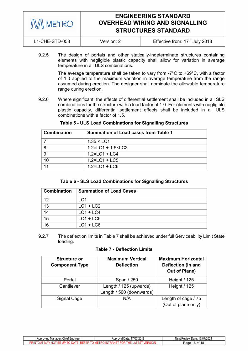
9.2.5 The design of portals and other statically-indeterminate structures containing elements with negligible plastic capacity shall allow for variation in average temperature in all ULS combinations.
The average temperature shall be taken to vary from -7°C to +69°C, with a factor of 1.0 applied to the maximum variation in average temperature from the range assumed during erection. The designer shall nominate the allowable temperature range during erection.
9.2.6 Where significant, the effects of differential settlement shall be included in all SLS combinations for the structure with a load factor of 1.0. For elements with negligible plastic capacity, differential settlement effects shall be included in all ULS combinations with a factor of 1.5.
Table 5 - ULS Load Combinations for Signalling Structures
Combination Summation of Load cases from Table 1
7 1.35 × LC1 8 1.2×LC1 + 1.5×LC2 9 1.2×LC1 + LC4 10 1.2×LC1 + LC5 11 1.2×LC1 + LC6
Table 6 - SLS Load Combinations for Signalling Structures
Combination Summation of Load Cases
12 LC1 13 LC1 + LC2 14 LC1 + LC4 15 LC1 + LC5 16 LC1 + LC6
9.2.7 The deflection limits in Table 7 shall be achieved under full Serviceability Limit State loading.
Table 7 - Deflection Limits
Structure or Component Type
Maximum Vertical Deflection
Maximum Horizontal Deflection (In and
Out of Plane)
Portal Span / 250 Height / 125 Cantilever Length / 125 (upwards)
Length / 500 (downwards) Height / 125
Signal Cage N/A Length of cage / 75 (Out of plane only)

ENGINEERING STANDARD OVERHEAD WIRING AND SIGNALLING
STRUCTURES STANDARD
L1-CHE-STD-058 Version: 2 Effective from: 17th July 2018
Approving Manager: Chief Engineer Approval Date: 17/07/2018 Next Review Date: 17/07/2021 PRINTOUT MAY NOT BE UP-TO-DATE; REFER TO METRO INTRANET FOR THE LATEST VERSION Page 17 of 18
10 Appendix A – Documentation Requirements
General
10.1.1 Design Documentation shall be prepared in accordance with the MTM Design and Technical Review Procedure L1-NAM-PRO-002.
10.1.2 All Design Drawings shall be produced in accordance with the conventions detailed in MTM Documentation L1-CHE-POL-001 Engineering Drawings Management Policy (IFC/As Builts), PTV Infrastructure Drafting Standards and AS 1100 Technical Drawing.
Drawings 10.2.1 Structural design drawings shall include:
• Requirements for all material grades, finishes and workmanship to meet this and other applicable Standards.
• Schedule of structures including
o Structure number
o Structure type (e.g. STC, TTC, Portal, SSA)
o Mast section and type
o Bridge or boom section and type (if applicable)
o Footing type
o Number and type of drop verticals
o Precamber and/or rake to members to satisfy deflection requirements
• Geotechnical design parameters, subgrade preparation or pile testing requirements (as applicable).
• Details of reinforced concrete footings, piles and pilecaps (as applicable).
• Envelopes of SLS and ULS design load combinations applicable at top of footing or top of pile, or at base of mast where connected to other structures.
• Details of steel members and connections, including illustration and procedure for tightening of any bolted connections with locknuts to ensure correct installation.
• Assumed temperature installation temperature range for statically indeterminate structures, where applicable.

ENGINEERING STANDARD OVERHEAD WIRING AND SIGNALLING
STRUCTURES STANDARD
L1-CHE-STD-058 Version: 2 Effective from: 17th July 2018
Approving Manager: Chief Engineer Approval Date: 17/07/2018 Next Review Date: 17/07/2021 PRINTOUT MAY NOT BE UP-TO-DATE; REFER TO METRO INTRANET FOR THE LATEST VERSION Page 18 of 18
Design Report
10.3.1 Requirements for the Design Report are provided in L1-CHE-STD-011.
10.3.2 Where assessment of existing structures is required, as for example where additional loading is proposed to be added or other significant modifications carried out to existing structures, the Design Report shall include:
• Description of the structure(s), including details of the original design load where known.
• Description of the methodology for data collection referencing all data sources (drawings, inspection reports, field measurements, geotechnical investigation, materials testing etc.). Copies of data documents that are not available by reference should be included in an appendix.
• Description of the structure condition. Copies of condition documents that are not available by reference should be included in an appendix.
• Description of findings from field geometry measurements, or justification if field geometry was not measured.
• Discussion of the methodology for capacity assessment including the basis for all material strengths and section capacities assumed in the load rating calculations, and the standards and other reference documents used.
• Discussion of the methodology for calculation of the load rating factor including key assumptions and details of software used.
• Discussion of the Critical Load Rating Factor for the structure for each of the nominated load combinations, including explanation of the element and design action responsible for the Critical Load Rating Factor.
• Detailed results of the structure condition assessment and load rating process, for each load rated structural component for each load combination.