p. 1 of 14 installation & owner’s...
TRANSCRIPT

P. 1 of 14
KUBOTA F-SERIES CAB
p/n: F5206
I
NS
TALL
AT
ION
& O
WN
ER
’S M
AN
UA
L
CAB INSTALLATION BEFORE YOU START HELPFUL REMINDERS: Read and understand all instructions before beginning. APPROXIMATE INSTALLATION TIME: 90 MINUTES (not including accessories) Page 2 Safety Information Page 3-4 Features and Accessories Page 5-6 Tractor Preparation (mount and wiring install) Page 7 Cab Installation Page 8 Operation Page 9 Cab Removal, Care and Maintenance Page 10-14 Service Parts
Manual p/n: 77700-05445 (p/n: F5206P1)
The contents of this envelope are the property of the owner. Be sure to leave with the owner when installation is complete.
Rev. F (11/4/2016)
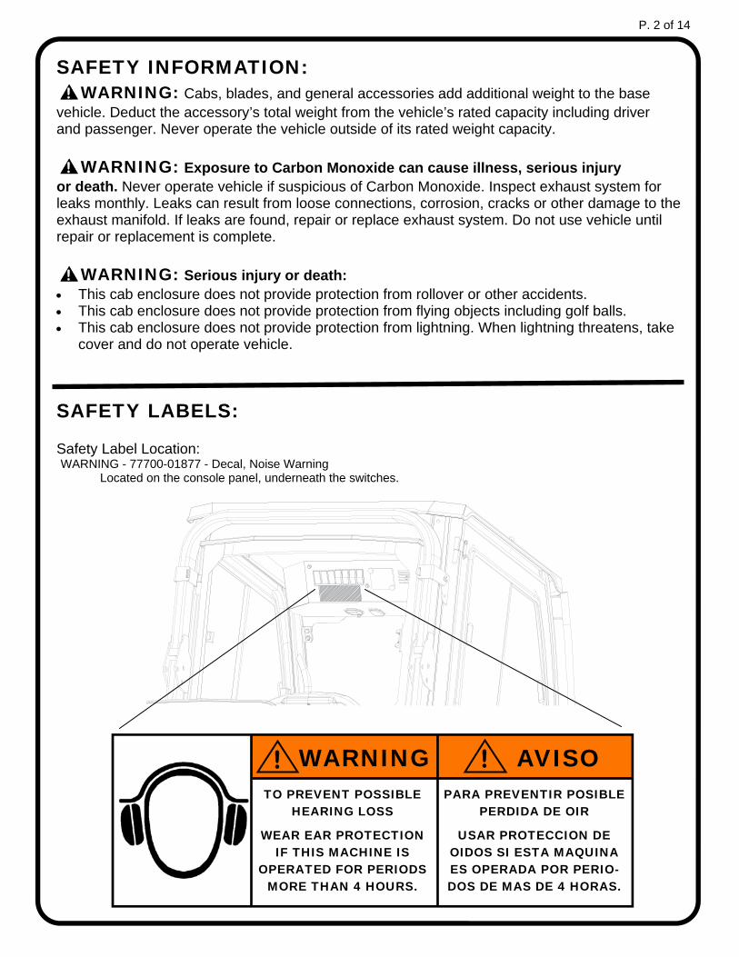
SAFETY INFORMATION: ! WARNING: Cabs, blades, and general accessories add additional weight to the base vehicle. Deduct the accessory’s total weight from the vehicle’s rated capacity including driver and passenger. Never operate the vehicle outside of its rated weight capacity.
! WARNING: Exposure to Carbon Monoxide can cause illness, serious injury or death. Never operate vehicle if suspicious of Carbon Monoxide. Inspect exhaust system for leaks monthly. Leaks can result from loose connections, corrosion, cracks or other damage to the exhaust manifold. If leaks are found, repair or replace exhaust system. Do not use vehicle until repair or replacement is complete.
! WARNING: Serious injury or death: This cab enclosure does not provide protection from rollover or other accidents. This cab enclosure does not provide protection from flying objects including golf balls. This cab enclosure does not provide protection from lightning. When lightning threatens, take
cover and do not operate vehicle.
SAFETY LABELS: Safety Label Location: WARNING - 77700-01877 - Decal, Noise Warning Located on the console panel, underneath the switches.
P. 2 of 14
TO PREVENT POSSIBLE HEARING LOSS
WEAR EAR PROTECTION IF THIS MACHINE IS
OPERATED FOR PERIODS MORE THAN 4 HOURS.
PARA PREVENTIR POSIBLE PERDIDA DE OIR
USAR PROTECCION DE OIDOS SI ESTA MAQUINA ES OPERADA POR PERIO-DOS DE MAS DE 4 HORAS.
AVISO WARNING ! !

KEY FEATURES OF THE F5206 CAB:
Large outer grab handles also perform as brush guards
Two (2) 8-LED Front Work Lights included
Heavy-Duty Pantograph Wiper system included
Pre-Assembled Cab: The main cab ships fully assembled with a mount and hardware kit.
Wiring, lights and wiper are pre-installed.
The mount kit is installed once and can remain on the tractor.
The cab can be removed as needed
and quickly re-installed to the mounts Large windows for maximum visibility Large sliding windows and venting
rear window for maximum ventilation Doors can be removed quickly Door hinge pins are of different
lengths for easier install
Lifting Rings provided: Accept lifting hooks up to 7/8” thick
Built-in Console Provides plug-and-play wiring for all accessories
Venting / removable rear window
Fans included in console for ventilation and windshield defrost
Swiveling Interior Light Standard in console
P. 3 of 14
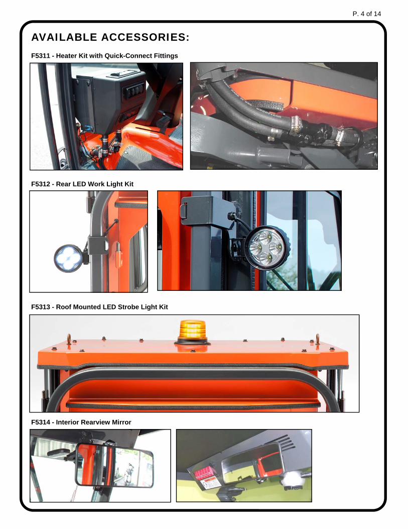
AVAILABLE ACCESSORIES: F5311 - Heater Kit with Quick-Connect Fittings
F5312 - Rear LED Work Light Kit
F5313 - Roof Mounted LED Strobe Light Kit
F5314 - Interior Rearview Mirror
P. 4 of 14
1. TRACTOR PREPARATION: MOUNT KIT INSTALL TOOLS REQUIRED: 13/16” SAE wrench or socket
Two (2) each, 12mm and 14mm Metric wrenches or sockets
1.1 Lift the engine bonnet to the upward position and move the seat into its forward position.
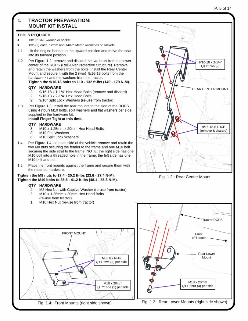
1.2 Per Figure 1.2, remove and discard the two bolts from the lower center of the ROPS (Roll-Over Protective Structure). Remove and retain the washers from the bolts. Install the Rear Center Mount and secure it with the 2 (two) 9/16-18 bolts from the hardware kit and the washers from the tractor. Tighten the 9/16-18 bolts to 110 - 132 ft-lbs (149 - 179 N-M).
QTY HARDWARE 2 9/16-18 x 1-1/4” Hex Head Bolts (remove and discard) 2 9/16-18 x 2-1/4” Hex Head Bolts 2 9/16” Split Lock Washers (re-use from tractor)
1.3 Per Figure 1.3, install the rear mounts to the side of the ROPS using 4 (four) M10 bolts, split washers and flat washers per side, supplied in the hardware kit.
Install Finger Tight at this time.
QTY HARDWARE 8 M10 x 1.25mm x 20mm Hex Head Bolts 8 M10 Flat Washers 8 M10 Split Lock Washers
1.4 Per Figure 1.4, on each side of the vehicle remove and retain the two M8 nuts securing the fender to the frame and one M10 bolt securing the side strut to the frame. NOTE: the right side has one M10 bolt into a threaded hole in the frame; the left side has one M10 bolt and nut.
1.5 Place the front mounts against the frame and secure them with the retained hardware.
Tighten the M8 nuts to 17.4 - 20.2 ft-lbs (23.6 - 27.4 N-M). Tighten the M10 bolts to 35.5 - 41.2 ft-lbs (48.1 - 55.8 N-M).
QTY HARDWARE 4 M8 Hex Nut with Captive Washer (re-use from tractor) 2 M10 x 1.25mm x 20mm Hex Head Bolts (re-use from tractor) 1 M10 Hex Nut (re-use from tractor)
Fig. 1.2 : Rear Center Mount
REAR CENTER MOUNT
9/16-18 x 2-1/4” QTY: two (2)
9/16-18 x 1-1/4” (remove & discard)
Fig. 1.3: Rear Lower Mounts (right side shown)
M10 x 20mm QTY: four (4) per side
Rear Lower Mount
Tractor ROPS
M8 Hex Nuts QTY: two (2) per side
M10 x 20mm QTY: one (1) per side
FRONT MOUNT
Fig. 1.4: Front Mounts (right side shown)
Front of Tractor
P. 5 of 14

2. TRACTOR PREPARATION: WIRING
TOOLS REQUIRED: Wire Cutters (for wire ties)
10mm Wrench or Socket
2.1 Remove the nuts from the tractor battery terminals and attach the ring terminals from the relay harness onto the battery. Connect red to positive and then black to negative.
2.2 Using a wire tie, secure the relay and fuse holder of the relay harness to a hole in the frame, above and forward of the battery, as shown in figure 2.2.
2.3 Work the relay harness toward the front of the tractor, under the deck, and secure the relay harness to the main vehicle harness using wire ties.
NOTE: Removing the right side front wheel will allow for better access to the frame for routing of the relay harness.
2.4 Locate the female bullet terminal for keyed power underneath the tractor, about a foot from the front of the fender, under the steering pedestal. Connect the male bullet terminal on the purple wire from the relay harness to the keyed power female bullet on the tractor.
2.5 Attach the end of the relay harness with the weather-pack connector to the frame near the right front mount.
Wire tie relay and fuse holder to
frame here
Fig, 2.2: Relay harness to battery connection
Fig, 2.4: Keyed Power Terminal (view under right fender)
WIRE DIAGRAMS
Relay Wire Harness
Female bullet terminal for keyed power
Purple wire from Relay harness
P. 6 of 14

3. CAB INSTALLATION TOOLS REQUIRED: Two (2) 3/4” and one (1) 1/2” SAE wrenches or sockets
Two (2) 14mm and one (1) 12mm Metric wrenches or sockets
QTY: HARDWARE 6 5/16-18 x 1” Flanged Head Bolts 2 1/2-13 x 1” Flanged Head Bolts 2 1/2-13 Flanged Nylon-Insert Nut
WARNING: Use only appropriately rated equipment to lift the cab.
NOTE: Total weight of the cab assembly without doors or accessories is approximately 230 lbs. Weight of the cab with doors, not including accessories, is approximately 340 lbs.
3.1 Replace the large thumb screws from the front of the ROPS with two M10 bolts from the hardware kit.
3.2 Fold the tractor ROPS down by removing the pin, lower it and secure it via the pin in the lowered position. Move the seat into its forward position.
3.3 Remove the doors from the cab (see section 4.3) to the reduce weight on the frame as the cab is lifted. The rear window can also be removed to further reduce the weight.
3.4 Remove the bolts securing the cab to the shipping pallet: 2 (two) bolts in each floorboard and 1 (one) bolt and nut in each rear mount.
NOTE: The pallet may be retained for seasonal storage of the cab.
3.5 Lift the cab off the pallet via the lifting rings in the roof. The cab will tip slightly forward as it’s lifted via the rings.
3.6 Carefully lower the cab over the tractor oriented per figure 3.5 until the floorboards are about 1/4 inch to 1/2 inch above the front mounts. Make sure the cab wire at the front right corner is free and not pinched underneath the floorboard.
3.7 Align the forward holes in the floorboard with the holes in the front mounts and install a 5/16” bolt through the 2 (two) holes in each floorboard and into the threaded inserts in the front mounts. Insert the bolts only far enough to catch the threads at this time. Use caution to avoid cross-threading factory installed threaded inserts.
3.8 Lower the cab until the rear mounts on the cab are close to the rear mounts on the side of the vehicle ROPS. Place a 1/2” bolt through each cab rear mount and install a nut underneath.
3.9 Make sure the rubber flap at the rear left of the cab folds neatly around the handle on the tractor and has no visible gaps against the rear panel and fender.
3.10 Raise and secure the ROPS into its upright position and over the upper ROPS mounts on the vehicle.
3.11 Check the fit of the cab, adjust as needed and secure the Upper Mount Clamp from the hardware box onto each upper ROPS mount with a 5/16” bolt (see fig. 3.11).
3.12 Tighten both 5/16” bolts in each floorboard, and the 1/2” bolts and nuts in each lower rear mount, and tighten the M10 bolts for the lower rear mounts.
Tighten all bolts to the following specifications: 1/2-13 - 80 - 96 ft-lbs (108 - 130 N-M) 5/16-18 - 17 - 20.5 ft-lbs (23.1 - 27.8) M10 - 35.5 - 41.2 ft-lbs (48.1 - 55.8 N-M)
3.13 Attach the weather-pack connector at the front, right of the cab to the connector from the relay harness, under the right front mount (see fig. 3.13).
NOTE: The lifting rings may be removed and replaced with bolts if desired. Two 5/16-18 x 1” bolts and replacement nylon washers are included in the hardware kit for this purpose.
5/16-18 x 1” QTY: two (2) per side
1/2-13 Nut QTY: one (1) per side
1/2-13 x 1” QTY: one (1) per side
Lifting Rings
Fig. 3.5: Cab onto Tractor orientation
Male plug from Cab
Female plug from Tractor
Fig. 3.13: Cab to Tractor plug connection
5/16-18 x 1” QTY: one (1) per side
Upper Mount Clamp
Fig. 3.11: Upper ROPS Clamps
P. 7 of 14
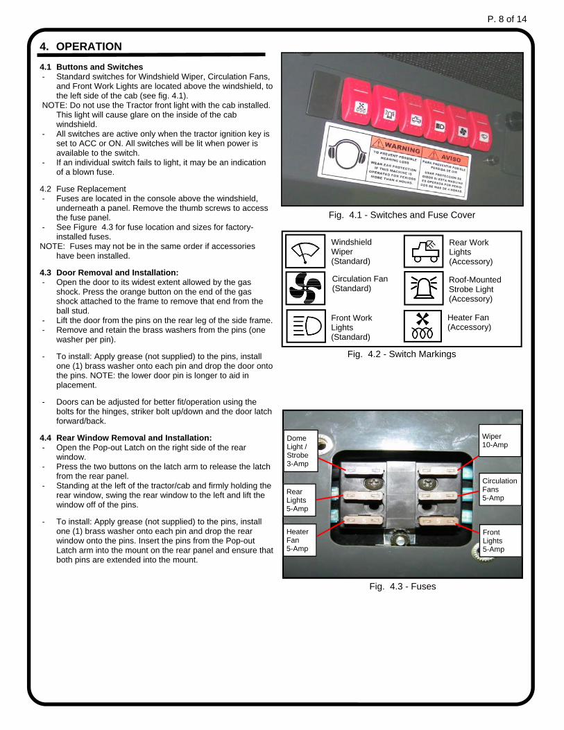
4. OPERATION 4.1 Buttons and Switches - Standard switches for Windshield Wiper, Circulation Fans,
and Front Work Lights are located above the windshield, to the left side of the cab (see fig. 4.1).
NOTE: Do not use the Tractor front light with the cab installed. This light will cause glare on the inside of the cab windshield.
- All switches are active only when the tractor ignition key is set to ACC or ON. All switches will be lit when power is available to the switch.
- If an individual switch fails to light, it may be an indication of a blown fuse.
4.2 Fuse Replacement - Fuses are located in the console above the windshield,
underneath a panel. Remove the thumb screws to access the fuse panel.
- See Figure 4.3 for fuse location and sizes for factory-installed fuses.
NOTE: Fuses may not be in the same order if accessories have been installed.
4.3 Door Removal and Installation: - Open the door to its widest extent allowed by the gas
shock. Press the orange button on the end of the gas shock attached to the frame to remove that end from the ball stud.
- Lift the door from the pins on the rear leg of the side frame. - Remove and retain the brass washers from the pins (one
washer per pin).
- To install: Apply grease (not supplied) to the pins, install one (1) brass washer onto each pin and drop the door onto the pins. NOTE: the lower door pin is longer to aid in placement.
- Doors can be adjusted for better fit/operation using the bolts for the hinges, striker bolt up/down and the door latch forward/back.
4.4 Rear Window Removal and Installation: - Open the Pop-out Latch on the right side of the rear
window. - Press the two buttons on the latch arm to release the latch
from the rear panel. - Standing at the left of the tractor/cab and firmly holding the
rear window, swing the rear window to the left and lift the window off of the pins.
- To install: Apply grease (not supplied) to the pins, install one (1) brass washer onto each pin and drop the rear window onto the pins. Insert the pins from the Pop-out Latch arm into the mount on the rear panel and ensure that both pins are extended into the mount.
Fig. 4.1 - Switches and Fuse Cover
Windshield Wiper (Standard)
Circulation Fan (Standard)
Rear Work Lights (Accessory)
Roof-Mounted Strobe Light (Accessory)
Front Work Lights (Standard)
Heater Fan (Accessory)
Fig. 4.2 - Switch Markings
Circulation Fans 5-Amp
Wiper 10-Amp
Front Lights 5-Amp
Dome Light / Strobe 3-Amp
Rear Lights 5-Amp
Heater Fan 5-Amp
Fig. 4.3 - Fuses
P. 8 of 14
5. CAB REMOVAL This cab is designed to allow removal of the cab
assembly per seasonal or other requirements. Mounts, wiring and plumbing are intended to remain on
the tractor for quick removal and re-installation. TOOLS REQUIRED: One (1) 1/2” and two (2) 3/4” and SAE wrenches or sockets
5.1 Detach the cab harness from the relay harness via the connector at the lower right, underneath the right front mount.
5.2 Detach the heater hoses (if installed) from the tractor via the quick disconnects located under the left front mount.
NOTE: If the cab is to remain off for extended periods, remove the fuse from the relay harness. NOTE: All approved electronic accessories are connected within the cab assembly and remain with the cab.
5.3 Remove the upper ROPS clamps from each side. 5.4 Fold the tractor ROPS down by removing the pin, lower
it and secure it via the pin in the lowered position. Move the seat into its forward position.
5.5 Remove and retain the two (2) 5/16-18 x 3/4” bolts from each floorboard and the 1/2-13 x 1” bolts and nuts from each lower rear mount.
NOTE: If the lifting rings (see figure 3.5) have been replaced with bolts, replace the center bolt on the roof into the side frame with the lifting rings.
5.6 Lift the cab off the tractor via the rings and place in a secure location.
Refer to Section 3 on Page 7 to re-install the cab onto the
tractor.
6. CARE AND MAINTENANCE NOTE: This manual includes instructions only relevant to the
Cab. Refer to the owner’s manual included with the tractor for any care and maintenance of the tractor.
6.1 Check and tighten hardware after 40 hours of operation. Periodically inspect and tighten hardware for the remainder of the unit’s life.
6.2 Be sure to regularly grease door and rear window hinge pins. Also lubricate moving parts in the door latches.
6.3 Wash with a mild soap or detergent. Do not use abrasives or harsh chemicals such as acetone to clean painted or glass surfaces.
P. 9 of 14
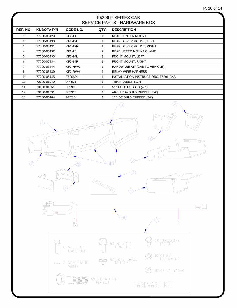
REF. NO. KUBOTA P/N CODE NO. QTY. DESCRIPTION
1 77700-05429 KF2-11 1 REAR CENTER MOUNT
2 77700-05430 KF2-12L 1 REAR LOWER MOUNT, LEFT
3 77700-05431 KF2-12R 1 REAR LOWER MOUNT, RIGHT
4 77700-05432 KF2-13 2 REAR UPPER MOUNT CLAMP
5 77700-05433 KF2-14L 1 FRONT MOUNT, LEFT
6 77700-05434 KF2-14R 1 FRONT MOUNT, RIGHT
7 77700-05444 KF2-HWK 1 HARDWARE KIT (CAB TO VEHICLE)
8 77700-05439 KF2-RWH 1 RELAY WIRE HARNESS
9 77700-05445 F5206P1 1 INSTALLATION INSTRUCTIONS, F5206 CAB
10 70000-01049 9PRO1 1 TRIM RUBBER (12”)
11 70000-01051 9PRO2 1 5/8” BULB RUBBER (40”)
13 77700-05484 9PR16 1 1” SIDE BULB RUBBER (24”)
12 70000-01391 9PRO9 1 ARCH PSA BULB RUBBER (34”)
F5206 F-SERIES CAB SERVICE PARTS - HARDWARE BOX
P. 10 of 14

REF. NO. KUBOTA P/N CODE NO. QTY. DESCRIPTION
1 77700-05426 KF2-09L 1 SIDE FRAME WITH RUBBER ONLY, LEFT
2 77700-05427 KF2-09R 1 SIDE PRAME WITH RUBBER ONLY, RIGHT
3 77700-05428 KF2-10 2 OUTER GRAB HANDLE
4 77700-01482 9PI01 4 7/8 POLY INSERT
5 70000-01396 9DL01K 2 STRIKER BOLT KIT (BOLT, NUT & GUARD)
6 70000-01024 9GS02A 2 BALL STUD FOR GAS SPRING
7 77700-05437 KF2-MWH 1 MAIN WIRE HARNESS
8 77700-05457 9HR03 2 RUBBER GROMMET (.44 ID X .94 OD)
9 77700-05422 KF2-06 1 REAR PANEL WITH RUBBER (WITHOUT WINDOW)
10 77700-05423 KF2-06W 1 REAR WINDOW ASSEMBLY
12 70000-01063 AC1001 4 SMALL GLASS INSULATING BUSHING
13 70000-01070 AC1008 4 RUBBER WASHER
14 70000-01061 9WL01 1 POP-OUT WINDSHIELD HINGE KIT
15 77700-05253 9PHW010-W 6 BRASS WASHER FOR WELD-ON HINGES
16 70000-01050 9PRO1 1 TRIM RUBBER (220”)
17 70000-01048 9PRO2 1 5/8” BULB RUBBER (180”)
19 77700-02505 9PR38 1 RUBBER, 3/4” SIDE BULB WITH 1/4” GRIP (180”)
11 77700-05483 WA-KF2RWHS 2 REAR WINDOW HINGE
18 70000-01391 9PRO9 1 ARCH PSA BULB RUBBER (34”)
F5206 F-SERIES CAB SERVICE PARTS - SIDE FRAMES AND REAR PANEL
P. 11 of 14

REF. NO. KUBOTA P/N CODE NO. QTY. DESCRIPTION
1 77700-05419 KF2-03 1 WINDSHIELD SUPPORT W/ CONSOLE
2 77700-05451 9PWA4A1-A 1 WIPER MOTOR ASSEMBLY
3 77700-05258 FP-01 1 GANGED FUSE BLOCK, 6 POSITION, ATC STYLE
4 77700-05438 KF2-DWH 2 WIRE HARNESS, DOUBLE
5 77700-05443 KF2-NWH 1 WIRE HARNESS, DOME LIGHT
6 70000-01318 OHC-1 2 AXIAL FAN. 80mm X 80mm X 38mm
7 70000-01156 OHC-5 2 SWITCH, SINGLE POSITION
8 70000-01157 OHC-6 1 SWITCH, DOUBLE POSITION HIGH & LOW
9 70000-01218 9PCD1-A 1 SWITCH COVER (FAN)
10 70000-01220 9PCD1-C 1 SWITCH COVER (WORK LIGHT)
11 70000-01221 9PCD1-D 1 SWITCH COVER (WIPER)
12 77700-05153 9HV2-01 4 SWITCH PANEL PLUG
13 77700-05420 KF2-04 1 CONSOLE PANEL (WITHOUT DOME LIGHT)
14 77700-05482 SM-KF2CONFC 1 FUSE COVER
15 77700-01877 9DL-173 1 DECAL, NOISE WARNING
16 77700-05170 9LEDDL-SA 2 LED SWIVEL DOME LIGHT W/ TERMINALS
17 77700-05456 9HR0080 2 VENT, 2” ROUND 360 DEG
18 77700-05455 9HR0081 2 2” VENT RETAINING RING
19 70000-01045 9PR20 1 1/2” WEATHER SEAL RUBBER (55”)
20 77700-01048 9PRO2 1 5/8” BULB RUBBER (170”)
F5206 F-SERIES CAB SERVICE PARTS - WINDSHIELD SUPPORT AND CONSOLE
NOTE: See page 6 for wire diagrams.
P. 12 of 14
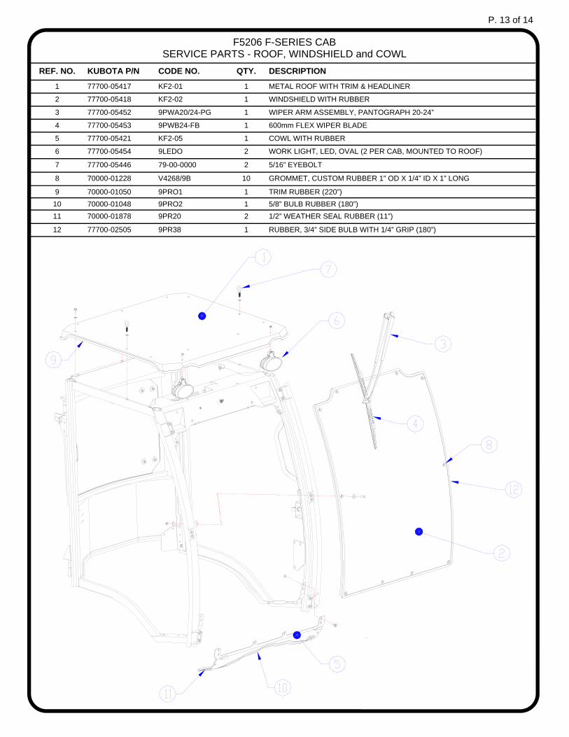
REF. NO. KUBOTA P/N CODE NO. QTY. DESCRIPTION
1 77700-05417 KF2-01 1 METAL ROOF WITH TRIM & HEADLINER
2 77700-05418 KF2-02 1 WINDSHIELD WITH RUBBER
3 77700-05452 9PWA20/24-PG 1 WIPER ARM ASSEMBLY, PANTOGRAPH 20-24”
4 77700-05453 9PWB24-FB 1 600mm FLEX WIPER BLADE
5 77700-05421 KF2-05 1 COWL WITH RUBBER
6 77700-05454 9LEDO 2 WORK LIGHT, LED, OVAL (2 PER CAB, MOUNTED TO ROOF)
7 77700-05446 79-00-0000 2 5/16” EYEBOLT
8 70000-01228 V4268/9B 10 GROMMET, CUSTOM RUBBER 1” OD X 1/4” ID X 1” LONG
9 70000-01050 9PRO1 1 TRIM RUBBER (220”)
10 70000-01048 9PRO2 1 5/8” BULB RUBBER (180”)
11 70000-01878 9PR20 2 1/2” WEATHER SEAL RUBBER (11”)
12 77700-02505 9PR38 1 RUBBER, 3/4” SIDE BULB WITH 1/4” GRIP (180”)
F5206 F-SERIES CAB SERVICE PARTS - ROOF, WINDSHIELD and COWL
P. 13 of 14

REF. NO. KUBOTA P/N CODE NO. QTY. DESCRIPTION
1 77700-05424 KF2-07L 1 DOOR ASSEMBLY (STEEL), LEFT
2 77700-05425 KF2-07R 1 DOOR ASSEMBLY (STEEL), RIGHT
3 77700-05447 9SW-KF2L 1 SLIDING DOOR WINDOW, LEFT
4 77700-05448 9SW-KF2R 1 SLIDING DOOR WINDOW, RIGHT
5 77700-05449 9GL-35X23L 1 LOWER DOOR WINDOW, SILKSCREENED, LEFT
6 77700-05450 9GL-35X23R 1 LOWER DOOR WINDOW, SILKSCREENED, RIGHT
7 77700-05435 KF2-08L 1 DOOR HINGES, LEFT (SET OF UPPER / LOWER)
8 77700-05436 KF2-08R 1 DOOR HINGES, RIGHT (SET OF UPPER / LOWER)
9 70000-01016 9DL01A 1 INSIDE ROTARY DOOR LATCH, LEFT (ON RIGHT DOOR)
10 70000-01017 9DL01B 1 INSIDE ROTARY DOOR LATCH, RIGHT (ON LEFT DOOR)
11 70000-01018 9DL01C 2 OUTSIDE ROTARY DOOR HANDLE W/ KEY
12 70000-01023 9GS02Q 2 DOOR GAS SPRING (12 3/8” EXTENDED LENGTH)
13 70000-01024 9GS02A 2 BALL STUD FOR GAS SPRING ON FRAME AND DOOR
14 77700-00279 9PR10 4 RUBBER FOR WINDOW (110”)
15 70000-01041 9PR17 2 RUBBER, 3/4” SIDE BULB WITH 1/8” GRIP (180”)
F5206 F-SERIES CAB SERVICE PARTS - DOORS
P. 14 of 14