pakistan deep water container port … karachi port is the primary seaport of pakistan that is aptly...
TRANSCRIPT
PAKISTAN DEEP WATER CONTAINER PORT PROJECT - KARACHI
Country: PAKISTAN Owner: Ministry of Ports and Shipping
Operated by Karachi Port Trust
Contractor: CHEC China Harbor Engineering Company Designer: Royal Haskoning
Construction period: 48 months
CLI’s involvement Sublicense granted to the Contractor and technical assistance provided during the
construction
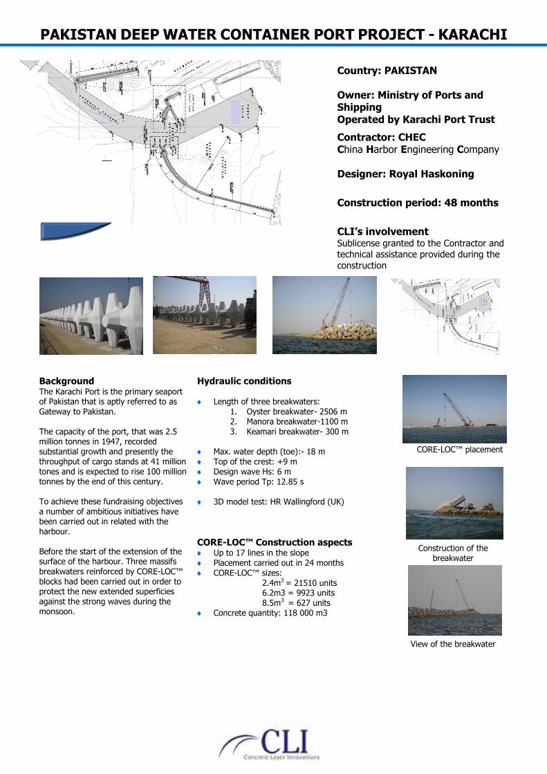
Background The Karachi Port is the primary seaport of Pakistan that is aptly referred to as Gateway to Pakistan.
The capacity of the port, that was 2.5 million tonnes in 1947, recorded substantial growth and presently the throughput of cargo stands at 41 million tones and is expected to rise 100 million tonnes by the end of this century. To achieve these fundraising objectives a number of ambitious initiatives have been carried out in related with the harbour. Before the start of the extension of the surface of the harbour. Three massifs breakwaters reinforced by CORE-LOC™ blocks had been carried out in order to protect the new extended superficies against the strong waves during the monsoon.
Hydraulic conditions Length of three breakwaters:
1. Oyster breakwater- 2506 m 2. Manora breakwater-1100 m
3. Keamari breakwater- 300 m
Max. water depth (toe):- 18 m Top of the crest: +9 m Design wave Hs: 6 m Wave period Tp: 12.85 s
3D model test: HR Wallingford (UK)
CORE-LOC™ Construction aspects Up to 17 lines in the slope Placement carried out in 24 months CORE-LOC™ sizes:
2.4m3 = 21510 units 6.2m3 = 9923 units 8.5m3 = 627 units
Concrete quantity: 118 000 m3
CORE-LOC™ placement
Construction of the breakwater
View of the breakwater

Co
Ba CICamithehaexpobathe Thprobyvecruwhstrmapro AllThcoquannepro
ontractor
ackground
TIC pacific miape Preston reine is to be see iron ore to C
ad to be built, xtraction zone.ort facilities alloarges which wie vessels moo
he loading faciotected agains
y cyclones eveery important. ucial role of prhich explains tructure. This sain land by a lotected with a
l of the units whailand and shnstruction. All
uarantines prond obtained in ecessary in ordoduction.
ning own a laegion where anet up. In orderChina, a new p40km away fr. The new Capows now to loill be used for
ored of shore.
ilities have to st the waves gn when the suThe breakwatrotecting the fthe height of tstructure is linlong causewayarmour rocks o
were fabricatehipped over dul the clearancecedures were due time. 30
der to deliver t
CAPE P
nd in the n iron r to export port facility rom the pe Preston oad the
loading
be fully generated urge is ter has a facilities, the ked to the y, only.
ed in uring the e of applied trips were the whole
♦♦♦♦♦♦
♦
PRESTO
Hydraulic c
♦ Length o♦ Max. wa♦ Top of th♦ Design w♦ Wave pe♦ MWL +6♦ 3D mode
2009 ♦ Cyclone
CORE-LOC™♦ CORE-LOC♦ 10 600 CO♦ Up to 27 l♦ Placement♦ Breakwate♦ CORE-LOC
3.9m3 6.2m3 8.5m3 11m3
♦ Concrete q
ON SINO
conditions
of CL structureater depth (toehe crest: +20wave Hs: 6.6 meriod Tp: 18 s6.10 el test: CHC (C
area with imp
™ ConstrucC™ units prodORE-LOC™ unlines in the slot carried out ier completed C™ sizes:
quantity: 69 5
O IRON
CAu
OCI
CCI
DSa
C20
CSuandu
e: 1750m e):-6m m m
Canada) in Jan
portant risk of
ction aspectduced abroadnits ope n 8 months in13months
500m3
N PORT
ountry ustralia WA
Owner ITIC Pacific M
ontractor ITIC Pacific M
Designer andwell (Can
onstructio008 - 2010
LI’s involvublicense grand technical uring the con
nuary
surge
ts
Mining
Mining
nada Vancou
on period
vement anted to the assistance pnstruction
CORE-LO(T
Loading o(Tha
Underlay
ver)
Contractor provided
C™ storing yaThailand)
n the vesselsailand)
yer profiling
ard
AL DUQM PORT
Country OMAN
Owner Ministry of Transport and Communication
Contractor CCC-STFA JV
Contractor Designer Royal Haskoning, UK
Construction period 2007 - 2010
CLI’s involvement Sublicense granted to the Contractor
and technical assistance provided during the construction
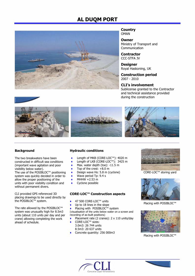
Background The two breakwaters have been
constructed in difficult sea conditions (important wave agitation and poor
visibility below water). The use of the POSIBLOC™ positioning
system was quickly decided in order to allow the proper positioning of the
units with poor visibility condition and without permanent divers.
CLI provided GPS referenced 3D
placing drawings to be used directly by the POSIBLOC™ system.
The rate allowed by the POSIBLOC™
system was unusually high for 8.5m3
units (about 110 units per day and per crane) allowing completing the work
ahead of schedule.
Hydraulic conditions
♦ Length of MKB (CORE-LOC™): 4020 m
♦ Length of LKB (CORE-LOC™): 3425 m
♦ Max. water depth (toe): -11.5 m ♦ Top of the crest: +8.0 m
♦ Design wave Hs: 5.8 m (cyclone)
♦ Wave period Tp: 9.4 s
♦ MHHW +2.53 m
♦ Cyclone possible
CORE-LOC™ Construction aspects
♦ 47 500 CORE-LOC™ units
♦ Up to 18 lines in the slope
♦ Placing with POSIBLOC™ system (visualisation of the units below water on a screen and recording of as-built positions)
♦ Placement rate (2 cranes): 2 x 110 units/day
♦ CORE-LOC™ sizes:
3.0m3: 26 744 units 8.5m3: 20 637 units
♦ Concrete quantity: 256 000m3
CORE-LOC™ storing yard
Placing with POSIBLOC™
Placing with POSIBLOC™
Ba A Buoutw Thin thetreTheapomequprothaCOun If eahaof unup ThACus
B
ackground
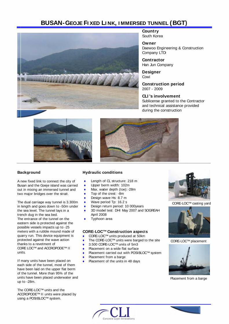
new fixed linkusan and the Gut in mixing anwo major bridg
he dual carriaglength and goe sea level. Thench dug in thhe entrance ofastern side is possible vessels eters with a ruuarry run. Thisotected againsanks to a reveORE LOC™ andnits.
many units haach side of theave been laid othe tunnel. M
nits have beenp to -28m.
he CORE-LOC™CCROPODE™ Ising a POSIBLO
BUSAN
k to connect thGoeje island wn immersed tuges over the st
ge way tunnel oes down to -5he tunnel layshe sea bed. f the tunnel onprotected agai impacts up toubble mound ms device equipst the wave acetment of d ACCROPODE
ave been placee tunnel, most on the upper f
More than 95%n placed under
™ units and thII units were pOC™ system.
N-GEOJE
he city of was carried unnel and trait.
is 3.300m 50m under in a
n the nst the o -25 made of ment is ction
E™ II
ed on of them
flat berm % of the rwater and
he placed by
♦♦♦♦♦♦♦
FIXED L
Hydraulic c
♦ Length o♦ Upper be♦ Max. wa♦ Top of th♦ Design w♦ Wave pe♦ Design r♦ 3D mode
April 200♦ Typhoon
CORE-LOC™♦ CORE-LOC♦ The CORE♦ 3.500 COR♦ Placement♦ Placement♦ Placement♦ Placement
LINK, IM
conditions
of CL structureerm width: 10
ater depth (toehe crest: -8mwave Hs: 8.7 meriod Tp: 16.2return period: el test: DHI M08 n area
™ ConstrucC™ units prodE-LOC™ units RE-LOC™ unitt on a wide flat carried out wt from a barget of the units
MMERSEDCSo
ODaCo
CHa
DCo
C20
CSuandu
e: 218 m 02m e):-28m
m s 10 000years
May 2007 and S
ction aspectduced at 50kmwere barged tts of 5m3 at surface with POSIBLOCe in 48 days
D TUNNELountry outh Korea
Owner aewoo Enginompany LTD
ontractor an Jun Comp
Designer owi
onstructio007 - 2009
LI’s involvublicense grand technical uring the con
SOGREAH
ts m
to the site
C™ system
L (BGT)
neering & CoD
pany
on period
vement anted to the assistance pnstruction
CORE-LOC
CORE-LOC
Placement
)
onstruction
Contractor provided
C™ casting ya
C™ placement
from a barge
ard

NEWBIGGIN BAY
Country United Kingdom
Owner City of Newbiggin
Contractor Westminster Dredging Company LTD
Designer Atkins
Construction period March 2007- August 2007
CLI’s involvement Sublicense granted to the Contractor
and technical assistance provided
during the construction
Background The City of Newbiggin has decided to
recharge the sandy beach along the shore
next to the bay promenade. In order to protect this newly reclaimed
beach against erosion, the hydraulic engineering office Atkins had designed an
off shore breakwater. The visual impact of the breakwater was a
predominant aspect of the project and it was crucial to have a very limited impact.
Consequently it was decided to create a low crest structure which was totally
submerged at high tide and partially visible at low tide.
This breakwater was covered of 3.9m3 units on both sides and on the top.
Furthermore, the structure had a wide crest where the blocks were laid on a flat
surface. Eventually the breakwater was
topped by a sculpture having its steel piles going through the CORE-LOC™ armouring.
The CORE-LOC™ units were transported by barges from the casting yard to the
breakwater.
Hydraulic conditions ♦ Length of CL structure: 200m
♦ Max. water depth (toe):-7m
♦ Top of the crest: +4.80m
♦ Design wave Hs: 5.7 m
♦ Wave period Tp: 12 s
♦ MHWS:+5.6
♦ 3D model test: DHI December 2004 ♦ Important tide range
CORE-LOC™ aspects ♦ Fabrication at 20km from the structure ♦ 1288 CORE-LOC™ units
♦ Placement completed in 2 months
♦ CORE-LOC™ sizes: 3.9m3
Particular aspects of the project ♦ Low and wide crest (10 lines on the berm)
♦ 6 Lines in the slope
♦ Transport of the units by barges
♦ Placement from a barge
CORE-LOC™ feeding barge
CORE-LOC™ placement
Casting yard

UMM AL – MARADEM SERVICE HARBOUR Country Kuwait
Owner Ministry pf Public Works (Special Projects Administration)
Contractor Gulf Dredging & General Construction C.O
Consultant KAMPSAX INTERNL & KEO Consultants
Construction period September 2004 – September 2005
CLI’s involvement Core Loc™ sublicense agreement including the supply of standard technical services, design review, formwork drawings, technical specifications, positioning drawings and site visits during construction.
1.4m³ Core Loc™ moulds Handling trial test
Background Umm Al Maradem island is located in the Persian Gulf, about 30 Kms off the south coast of Kuwait The one square kilometer island requires to be serviced by a new harbour for the coast guard. The 500m long breakwater exposed to the south waves required concrete armouring. The original design called for 10 000 m³ of tetrapods. The core Loc™ single layer was preferred since it saved 4 000m³ of armour concrete. The 2 000 Core Loc™ units were cast on the island using materials supplied from the main land.
Hydraulic conditions ♦ Hs: 4.3m ♦ Tp: 9.3 sec ♦ Design water level: +3.3m ♦ No physical modelling study but
unit weights were increased to the next size up.
Construction aspects ♦ Total project duration: about 12
months for the construction of the port.
♦ 15 forms of three Core Loc™ sizes were made locally: 1.4m³, 2.4m³ and 5.0m³ (roundhead).
♦ Land placement using theodolite method.
♦ 3 site visits by CLI.

IDKU LNG TERMINAL Country Egypt
Owner Egyptian LNG (ELNG)
Contractor APP consortium Arichirodon
Construction (Overseas) C.O. S.A. and Petrojet
Designer - FEED design by SOGREAH Consultants
- Final design by COWI
Laboratory DHI
Construction period May 2003 – December 2004
CLI’s involvement Sublicense granted to Petrojet and technical assistance: for the casting operations: to Petrojet for the placement: to Archirodon
View of one 11 m³Core loc™ block cast
Breakwater seaside view
Background The project is located east of Alexandria, in Abu Quir bay. The marine works package included the construction of a 900 m long offshore breakwater. Total volume of Core Loc™ concrete installed: 62 700m³.
Hydraulic conditions ♦ Max water depth: -11.5m ♦ Max water level: +1.09m ♦ Design wave Hs: 6.3m ♦ Tp: 16.6 sec.
Construction aspects ♦ Number of moulds
(locally made): 6.2m³: 30 sets 11.0m³: 40 sets.
♦ Number of Core Loc™ units 3 200 units of 6.2m³ (rear side) 3 900 units of 11m³ (seaside + roundheads).
♦ Placement with floating equipment equipped with DGPS.
♦ Nine site visits by CLI.

FUJAIRAH NAVAL BASE
Country United Arab Emirates
Owner Directorate of Military Works
Contractor Sixco Limited, Dubai
Designer Mouchel, Middle-East
Construction period Started in June 2002
CLI’s involvement Core-Loc® sublicense granted to the Contractor and technical assistance provided during design (modeling) and construction.
Background New Naval Base constructed in Fujairah, east of the UAE. The port is protected by two breakwaters
- main breakwater: 1 100 lm - lee breakwater: 550 lm
The trunks are armored with 3m³ Core-Loc® units on the seaside. Roundheads are armored with 5m³ units. Total quantity of armour concrete is about 45 000m³
Hydraulic conditions ♦ Max. waterdepth: -14m ♦ Hs= 4.7 m, T = 9 sec. ♦ Crest elevation: +8m ♦ 2D and 3D model tests at
Sogreah laboratory Construction aspects ♦ 40 Core-Loc® moulds used
during 12 months casting period
♦ Placement of 14 500 units by land crane equipped with GPS. Control by divers.
♦ 6 site visits by CLI
Casting 5m³ units
Progress on main breakwater
RAS LAFFAN COMMON COOLING WATER SYSTEM
Country Qatar
Owner Qatar Petroleum Company
Contractor Grandi Lavori Fincosit Middle East (W.L.L.)
Designer Technital, Italy
Construction period Started in September 2002
CLI’s involvement Sublicense granted to the Contractor and technical assistance provided during design (modeling) and construction.
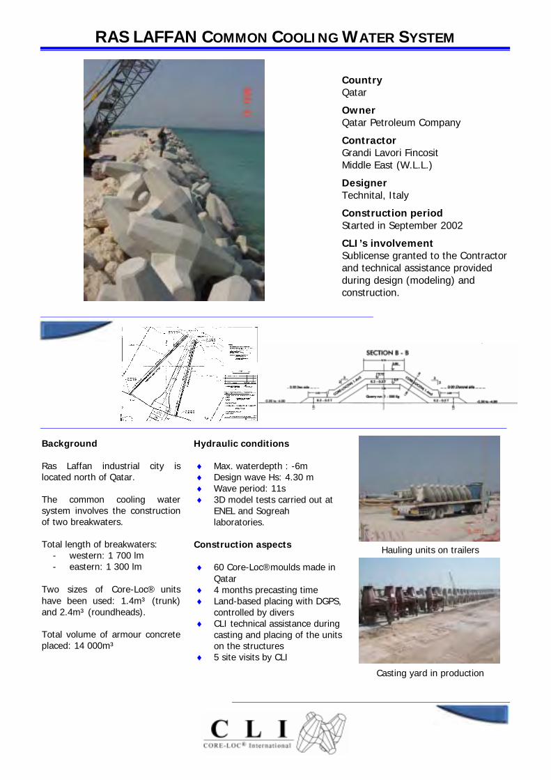
Background Ras Laffan industrial city is located north of Qatar. The common cooling water system involves the construction of two breakwaters. Total length of breakwaters:
- western: 1 700 lm - eastern: 1 300 lm
Two sizes of Core-Loc® units have been used: 1.4m³ (trunk) and 2.4m³ (roundheads). Total volume of armour concrete placed: 14 000m³
Hydraulic conditions ♦ Max. waterdepth : -6m ♦ Design wave Hs: 4.30 m ♦ Wave period: 11s ♦ 3D model tests carried out at
ENEL and Sogreah laboratories.
Construction aspects ♦ 60 Core-Loc® moulds made in
Qatar ♦ 4 months precasting time ♦ Land-based placing with DGPS,
controlled by divers ♦ CLI technical assistance during
casting and placing of the units on the structures
♦ 5 site visits by CLI
Hauling units on trailers
Casting yard in production

HALUL HARBOUR REFURBISHMENT – PHASE 1 Country Qatar
Owner Qatar Petroleum Company
Contractor Archirodon Construction (Overseas) CO. S.A. Dubai Branch
Consultant COWI ALMOAYED GULF
Construction period November 2001- September 2002
CLI’s involvement Sublicense granted to the Contractor and technical assistance provided during design (modeling) and construction
Plan view
Background The project is on an island located on the western part of Qatar. The first works phase of the Halul harbour refurbishment works included the extension of the Western breakwater by about 600 meters. The existing main (East) breakwater is planed to be repositioned on a future phase operation. The entire length of the western breakwater extension is protected with CORE-LOC®. Three sizes of CORE-LOC® units were used: 0.7, 1.4 and 2.4 m³. About 6 000 units representing 13 500 m³ of armour concrete were made.
Hydraulic conditions ♦ Max. waterdepth : -11m CD ♦ Design wave Hs: from 3.80 to
4.40 m ♦ Wave period Tp: 7s ♦ 3D model tests were carried
out by the DHI in Oct. 2002 Construction aspects ♦ 49 CORE-LOC® moulds – 110
days precasting ♦ Land-based placing (2 shifts /
day) ♦ CLI follow-up during
construction – 5 site visits
Storage on 3 levels
Placing units on the crest

09/01 MFN
Gela breakwater strengthening
CountryItaly
OwnerPort of Gela - Sicily
ContractorDragomar – Di Vicenzo
DesignerPr L. Franco – M. Napolitano
Date2001-2002
Sogreah's services◗ Technical assistance within the
context of a licence agreement for the use of the CORE-LOC™ technique
Context The 1.2-km long offshore caisson breakwater of Gela industrial harbour on the SW coast of Sicily was built in the early 60s. The 60 caissons (20.4 m x 14.0 m) are seated on a thin rubble foundation lying in 12-13 m of water. The breakwater is quite damaged and needs strengthening.The Contractor proposed an alternative with CORE-LOC™ blocks so as to meet the strict limits for permissible overtopping flows under design storm wave conditions (0.1 l/m/s with the 1-year storm and 1.0 l/m/s with the 100-year storm) and for the
tolerable hydraulic damage of the armour under the 100-year storm. The breakwater is to be protected with 3.9 m3 and 5 m3 blocks.Fabrication of the CORE-LOC™ blocks started at Gela early in 2001 with block placement scheduled for the second half of 2001 and 2002.
Hydraulic conditions◆ Maximum water depth beyond
breakwaters: 13 m◆ Significant wave height
Hs = 5.4 m◆ Wave period Tp = 12.8 s
Sogreah's role Throughout the works Sogreah provided technical assistance to the Contractor.This involved supplying the necessary technical information for applying the CORE-LOC™
technique and training of the placing gang. Positioning drawings were produced in close liaison with the Contractor in order to take into account the equipment being used and the anticipated placing schedule.Sogreah's specialist made several site visits to ensure that the CORE-LOC™ technique was correctly applied and to upgrade the placement rate and quality.

12/00 MFN
Tory Island harbour extension
CountryIreland
OwnerDepartment of Marine and Natural Resources
ContractorIrishenco Ltd
Date1999-2000
Sogreah's services◗ Technical assistance within the
context of a licence agreement for the use of the CORE-LOC™
technique
Context Tory Island, at the north-western end of Ireland, is the country's remotest island. It is 5 km long and 2.5 km wide, and has only about 175 inhabitants. Tory Island has a daily ferry service but is sometimes completely cut off from the rest of the world for several days, or even weeks when the weather is very bad.The aim of the project was to improve access conditions at the harbour, in particular to enable the ferry to enter and berth safely regardless of tide level. The breakwater is protected by a facing of 5 m3 CORE-LOC™
artificial blocks. As the island is so isolated, lying 15 km offshore, the blocks were fabricated on the mainland and then transported there by barge.
Hydraulic conditions◆ Maximum water depth beyond
breakwaters: 7.5 m◆ Significant wave height
Hs = 5.8 m◆ Wave period Tp = 18 s Sogreah's role Throughout the works Sogreah provided technical assistance to the contractor.This involved supplying the
necessary technical information for understanding and applying the CORE-LOC® technique and preparing positioning drawings in close liaison with the contractor in order to take into account the equipment being used and the anticipated placing schedule.Sogreah's specialist made several site visits to deal with questions from the owner and contractor, and to ensure that the CORE-LOC® technique was correctly applied.