paper no. 4374 - ohio university homepage | ohio … compositional differences between the deposited...
TRANSCRIPT

*Currently works for Baker Hughes.
INVESTIGATION OF ENVIRONMENTAL EFFECTS ON INTRINSIC AND GALVANICCORROSION OF MILD STEEL WELDMENT IN CO2 ENVIRONMENT
Lei Huang*, Bruce Brown, Srdjan NesicInstitute for Corrosion and Multiphase Technology (ICMT)Department of Chemical and Biomolecular EngineeringOhio University, 342 W. State St., Athens, OH 45701
ABSTRACT
Localized corrosion of carbon steel welds has been thought to arise primarily from galvanic effects dueto compositional differences between the deposited weld metal, the parent steel, and the heat affectedzone induced by the welding process. The location and morphology of the preferential corrosion isinfluenced by a complex interaction of environmental parameters.
The effects of salt concentration and temperature on intrinsic and galvanic corrosion of the non-alloyedstandard carbon steel weldment in CO2 environments have been investigated using different types ofelectrochemical techniques. Experimental results show that for the non-alloyed standard weldment, theintrinsic corrosion rates of parent metal, heat affected zone (HAZ) and weld metal are not significantlydifferent, but the corrosion of weld metal becomes worse and the parent metal is protected due to thegalvanic effects between the segments. The experimental results also show that an increase of saltconcentration (1~10 wt.% NaCl) significantly affected the intrinsic corrosion rate in a nonlinear fashion.The galvanic currents were unaffected by the different salt concentrations.
Keywords: micro-electrochemical cell, mild steel, CO2 corrosion, weldment
INTRODUCTION
For the oil and gas industry, welding is a fundamental process in the construction of transportationpipelines, production tubing, and other related operational facilities. The welding process connectsmetallic structures by melting a filler material in between the two structures at high temperature. Carbonsteel is by far the most frequently welded metallic material in all heavy industrial applications includingthe petroleum and petrochemical industry1. Carbon steel weldment may experience all classical forms ofcorrosion depending upon the environment to which it is exposed1. Weldment naturally possesscompositional and microstructural heterogeneities, therefore, the corrosion of a weldment appears to bemore erratic and is difficult to predict.
According to its special structures, a weldment can be divided into three sections1: weld metal, heataffected zone (HAZ), and parent metal. A schematic representation of a weldment cut directly from a
1
Paper No.
4374
©2014 by NACE International. Requests for permission to publish this manuscript in any form, in part or in whole, must be in writing to NACE International, Publications Division, 1440 South Creek Drive, Houston, Texas 77084.The material presented and the views expressed in this paper are solely those of the author(s) and are not necessarily endorsed by the Association.
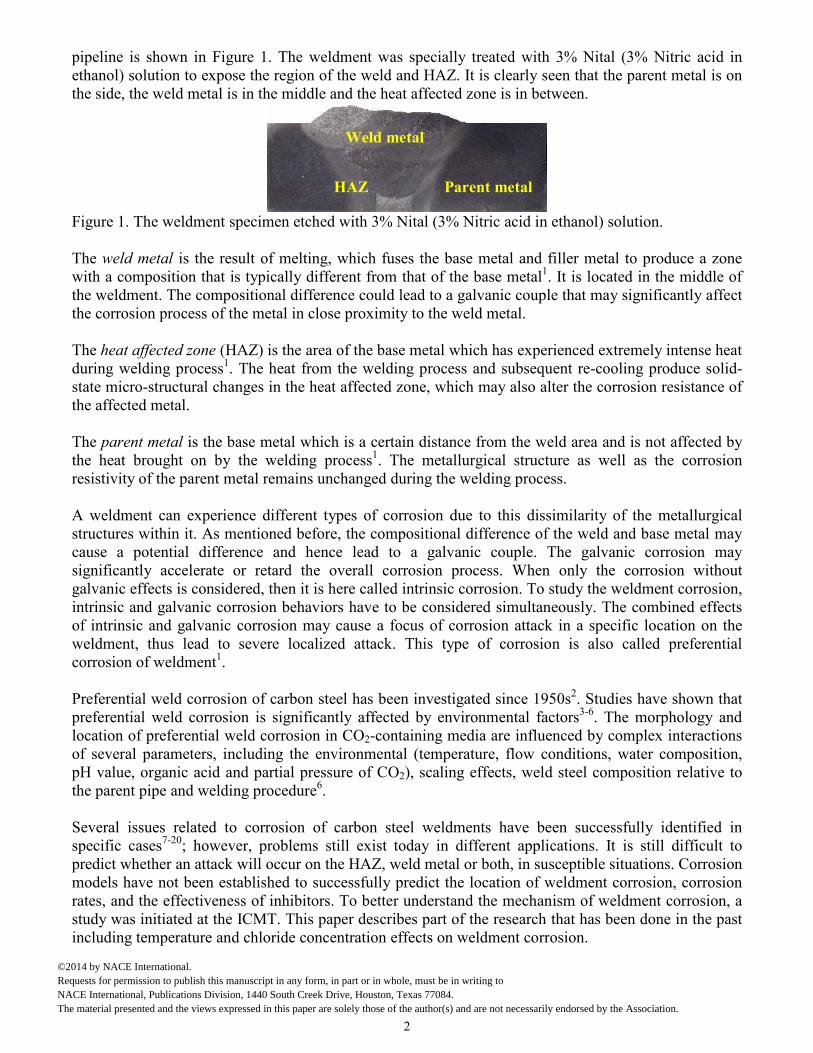
pipeline is shown in Figure 1. The weldment was specially treated with 3% Nital (3% Nitric acid inethanol) solution to expose the region of the weld and HAZ. It is clearly seen that the parent metal is onthe side, the weld metal is in the middle and the heat affected zone is in between.
Figure 1. The weldment specimen etched with 3% Nital (3% Nitric acid in ethanol) solution.
The weld metal is the result of melting, which fuses the base metal and filler metal to produce a zonewith a composition that is typically different from that of the base metal1. It is located in the middle ofthe weldment. The compositional difference could lead to a galvanic couple that may significantly affectthe corrosion process of the metal in close proximity to the weld metal.
The heat affected zone (HAZ) is the area of the base metal which has experienced extremely intense heatduring welding process1. The heat from the welding process and subsequent re-cooling produce solid-state micro-structural changes in the heat affected zone, which may also alter the corrosion resistance ofthe affected metal.
The parent metal is the base metal which is a certain distance from the weld area and is not affected bythe heat brought on by the welding process1. The metallurgical structure as well as the corrosionresistivity of the parent metal remains unchanged during the welding process.
A weldment can experience different types of corrosion due to this dissimilarity of the metallurgicalstructures within it. As mentioned before, the compositional difference of the weld and base metal maycause a potential difference and hence lead to a galvanic couple. The galvanic corrosion maysignificantly accelerate or retard the overall corrosion process. When only the corrosion withoutgalvanic effects is considered, then it is here called intrinsic corrosion. To study the weldment corrosion,intrinsic and galvanic corrosion behaviors have to be considered simultaneously. The combined effectsof intrinsic and galvanic corrosion may cause a focus of corrosion attack in a specific location on theweldment, thus lead to severe localized attack. This type of corrosion is also called preferentialcorrosion of weldment1.
Preferential weld corrosion of carbon steel has been investigated since 1950s2. Studies have shown thatpreferential weld corrosion is significantly affected by environmental factors3-6. The morphology andlocation of preferential weld corrosion in CO2-containing media are influenced by complex interactionsof several parameters, including the environmental (temperature, flow conditions, water composition,pH value, organic acid and partial pressure of CO2), scaling effects, weld steel composition relative tothe parent pipe and welding procedure6.
Several issues related to corrosion of carbon steel weldments have been successfully identified inspecific cases7-20; however, problems still exist today in different applications. It is still difficult topredict whether an attack will occur on the HAZ, weld metal or both, in susceptible situations. Corrosionmodels have not been established to successfully predict the location of weldment corrosion, corrosionrates, and the effectiveness of inhibitors. To better understand the mechanism of weldment corrosion, astudy was initiated at the ICMT. This paper describes part of the research that has been done in the pastincluding temperature and chloride concentration effects on weldment corrosion.
Weld metal
Parent metalHAZ
2
©2014 by NACE International. Requests for permission to publish this manuscript in any form, in part or in whole, must be in writing to NACE International, Publications Division, 1440 South Creek Drive, Houston, Texas 77084.The material presented and the views expressed in this paper are solely those of the author(s) and are not necessarily endorsed by the Association.
EXPERIMENTAL SET UP
All the experiments in this study were conducted in a glass cell under atmospheric pressure conditions.The following paragraphs describe the experimental setup and procedures.
Sample Preparation
A weldment specimen was made from a carbon steel pipe sample that had a weld. All experiments wereperformed on a “standard weldment” which has no alloying metals in the weld material. Thecompositions of parent and weld materials are given in Table 1. It appears that there is no significantdifference between the compositions of parent and weld material.
Table 1. Elemental analysis (wt.%) of parent metal and filler material of the weldment.
Element Al As C Co Cr Cu Fe Mn Mo Nb Ni
Parent 0.037% 0.004% 0.21% 0.002% 0.049% 0.021% 98.3% 1.01% 0.010% 0.010% 0.024%
Weld 0.013% 0.005% 0.12% 0.002% 0.042% 0.046% 98.2% 1.07% 0.013% 0.005% 0.033%
Element P S Sb Si Sn Ta Ti V W Zn Zr
Parent 0.013% 0.005% 0.007% 0.27% 0.004% 0.030% 0.003% 0.002% 0.016% 0.001 0.002%
Weld 0.012% 0.007% 0.008% 0.39% 0.004% 0.031% 0.002% 0.003% 0.014% 0.001% 0.003%
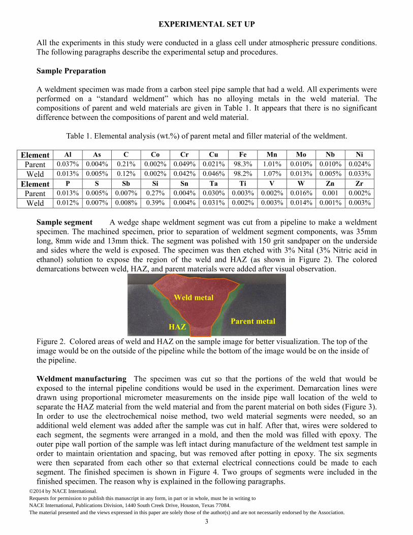
Sample segment A wedge shape weldment segment was cut from a pipeline to make a weldmentspecimen. The machined specimen, prior to separation of weldment segment components, was 35mmlong, 8mm wide and 13mm thick. The segment was polished with 150 grit sandpaper on the undersideand sides where the weld is exposed. The specimen was then etched with 3% Nital (3% Nitric acid inethanol) solution to expose the region of the weld and HAZ (as shown in Figure 2). The coloreddemarcations between weld, HAZ, and parent materials were added after visual observation.
Figure 2. Colored areas of weld and HAZ on the sample image for better visualization. The top of theimage would be on the outside of the pipeline while the bottom of the image would be on the inside ofthe pipeline.
Weldment manufacturing The specimen was cut so that the portions of the weld that would beexposed to the internal pipeline conditions would be used in the experiment. Demarcation lines weredrawn using proportional micrometer measurements on the inside pipe wall location of the weld toseparate the HAZ material from the weld material and from the parent material on both sides (Figure 3).In order to use the electrochemical noise method, two weld material segments were needed, so anadditional weld element was added after the sample was cut in half. After that, wires were soldered toeach segment, the segments were arranged in a mold, and then the mold was filled with epoxy. Theouter pipe wall portion of the sample was left intact during manufacture of the weldment test sample inorder to maintain orientation and spacing, but was removed after potting in epoxy. The six segmentswere then separated from each other so that external electrical connections could be made to eachsegment. The finished specimen is shown in Figure 4. Two groups of segments were included in thefinished specimen. The reason why is explained in the following paragraphs.
Weld metal
Parent metalHAZ
3
©2014 by NACE International. Requests for permission to publish this manuscript in any form, in part or in whole, must be in writing to NACE International, Publications Division, 1440 South Creek Drive, Houston, Texas 77084.The material presented and the views expressed in this paper are solely those of the author(s) and are not necessarily endorsed by the Association.

Figure 3. Initial metal cuts in weldment sample to separate parent material from HAZ and HAZ fromweld material.
Figure 4. A picture of the weldment sample used in the experiment.
Each weldment surface was polished by silicon carbide sand paper, up to 600 grit, before it was tested.After polishing, the specimen was immersed in an isopropyl alcohol ultrasonic bath for 1 to 2 minutesand then air dried.
Experimental procedure
The experiment was performed in a glass cell as shown in Figure 5. A Saturated Calomel Electrode wasused as the reference electrode. The counter electrode was a platinum wire. The glass cell was filledwith 2 liters of de-ionized water and the required amount of NaCl to meet the designated chloride ionconcentration. Cell temperature was controlled by a hot plate with a thermocouple feedback. Before thetest, the solution was deoxygenated by purging with CO2 gas for 40 minutes to 1 hour. Purging of theglass cell with CO2 was maintained during the test period. When the desired temperature was obtained,the pH of the test solution was adjusted from equilibrium pH to the desired pH by adding adeoxygenated sodium bicarbonate solution. A weld segment specimen was then placed into the solutionand all electrical connections were made externally for electrochemical monitoring.
Figure 5. Electrochemical Glass-cell Set-up
4
©2014 by NACE International. Requests for permission to publish this manuscript in any form, in part or in whole, must be in writing to NACE International, Publications Division, 1440 South Creek Drive, Houston, Texas 77084.The material presented and the views expressed in this paper are solely those of the author(s) and are not necessarily endorsed by the Association.
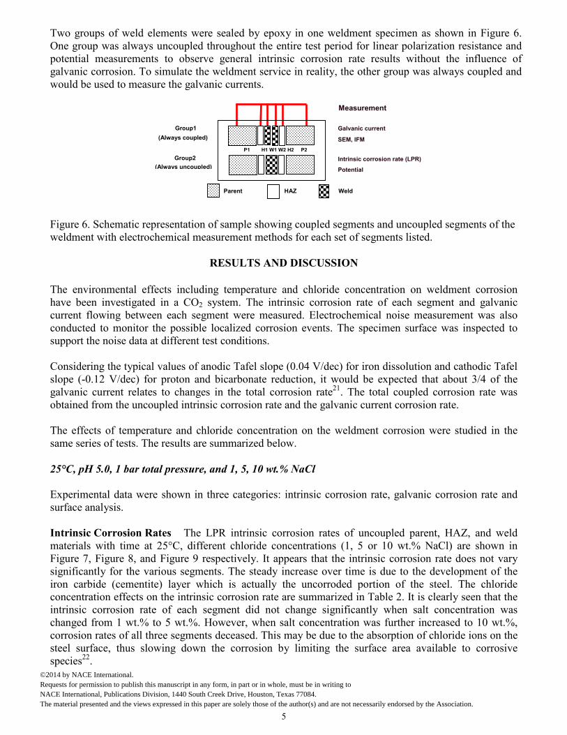
Two groups of weld elements were sealed by epoxy in one weldment specimen as shown in Figure 6.One group was always uncoupled throughout the entire test period for linear polarization resistance andpotential measurements to observe general intrinsic corrosion rate results without the influence ofgalvanic corrosion. To simulate the weldment service in reality, the other group was always coupled andwould be used to measure the galvanic currents.
Figure 6. Schematic repweldment with electroc
The environmental effhave been investigatedcurrent flowing betweconducted to monitorsupport the noise data a
Considering the typicalslope (-0.12 V/dec) fogalvanic current relateobtained from the unco
The effects of temperasame series of tests. Th
25°C, pH 5.0, 1 bar tot
Experimental data wersurface analysis.
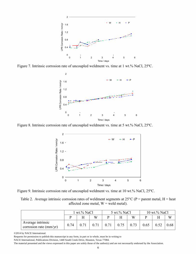
Intrinsic Corrosion Rmaterials with time atFigure 7, Figure 8, andsignificantly for the vairon carbide (cementitconcentration effects ointrinsic corrosion ratchanged from 1 wt.%corrosion rates of all thsteel surface, thus slospecies22.
Group1 Galvanic current
SEM, IFM
Intrinsic corrosion rate (LPR)
(Always coupled)
Group2
Measurement
2
©2014 by NACE International. Requests for permission to publish thiNACE International, Publications DivThe material presented and the views
resentation of sahemical measure
RES
ects including tein a CO2 syste
en each segmentthe possible locat different test co
values of anodicr proton and bics to changes inupled intrinsic co
ture and chloride results are sum
al pressure, and
e shown in three
ates The LPR25°C, differentFigure 9 respec
rious segments.e) layer whichn the intrinsic coe of each segmeto 5 wt.%. Howeree segments decwing down the
(Always uncoupled)
P
s manuscript in any form,ision, 1440 South Creek Dexpressed in this paper ar
P1 H1 W1 W2 H2 P
mple showing coupled segments and uncoupled segments of thement methods for each set of segments listed.
ULTS AND DISCUSSION
mperature and chloride concentration on weldment corrosionm. The intrinsic corrosion rate of each segment and galvanicwere measured. Electrochemical noise measurement was also
lized corrosion events. The specimen surface was inspected tonditions.
Tafel slope (0.04 V/dec) for iron dissolution and cathodic Tafelarbonate reduction, it would be expected that about 3/4 of thethe total corrosion rate21. The total coupled corrosion rate wasrrosion rate and the galvanic current corrosion rate.
e concentration on the weldment corrosion were studied in themarized below.
1, 5, 10 wt.% NaCl
categories: intrinsic corrosion rate, galvanic corrosion rate and
intrinsic corrosion rates of uncoupled parent, HAZ, and weldchloride concentrations (1, 5 or 10 wt.% NaCl) are shown intively. It appears that the intrinsic corrosion rate does not varyThe steady increase over time is due to the development of theis actually the uncorroded portion of the steel. The chloriderrosion rate are summarized in Table 2. It is clearly seen that thent did not change significantly when salt concentration wasver, when salt concentration was further increased to 10 wt.%,eased. This may be due to the absorption of chloride ions on thecorrosion by limiting the surface area available to corrosive
Potential
arent HAZ Weld
5
in part or in whole, must be in writing to rive, Houston, Texas 77084.
e solely those of the author(s) and are not necessarily endorsed by the Association.
0
0.4
0.8
1.2
1.6
2
0 1 2 3 4 5 6
LP
RC
orr
osi
on
Rate
/m
m/y
rTime / days
W H P
Figure 7. Intrinsic corrosion rate of uncoupled weldment vs. time at 1 wt.% NaCl, 25ºC.
0
0.4
0.8
1.2
1.6
2
0 1 2 3 4 5 6
LP
RC
orr
osio
nR
ate
/m
m/y
r
Time / days
W H P
Figure 8. Intrinsic corrosion rate of uncoupled weldment vs. time at 5 wt.% NaCl, 25ºC.
0
0.4
0.8
1.2
1.6
2
0 1 2 3 4 5 6
LP
RC
orr
osio
nR
ate
/m
m/y
r
Time / days
W H P
Figure 9. Intrinsic corrosion rate of uncoupled weldment vs. time at 10 wt.% NaCl, 25ºC.
Table 2. Average intrinsic corrosion rates of weldment segments at 25°C (P = parent metal, H = heataffected zone metal, W = weld metal).
1 wt.% NaCl 5 wt.% NaCl 10 wt.% NaCl
P H W P H W P H W
Average intrinsiccorrosion rate (mm/yr) 0.74 0.71 0.71 0.71 0.75 0.73 0.65 0.52 0.68
6
©2014 by NACE International. Requests for permission to publish this manuscript in any form, in part or in whole, must be in writing to NACE International, Publications Division, 1440 South Creek Drive, Houston, Texas 77084.The material presented and the views expressed in this paper are solely those of the author(s) and are not necessarily endorsed by the Association.
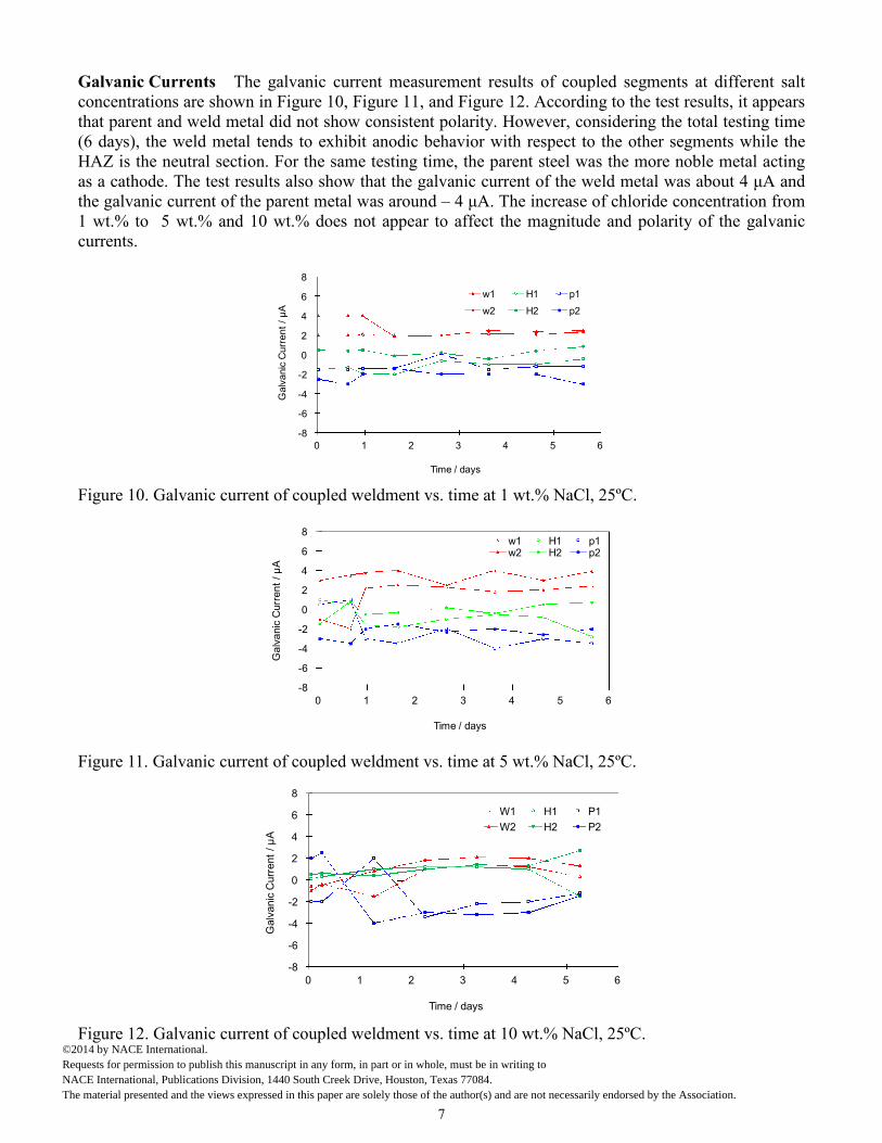
Galvanic Currents The galvanic current measurement results of coupled segments at different saltconcentrations are shown in Figure 10, Figure 11, and Figure 12. According to the test results, it appearsthat parent and weld metal did not show consistent polarity. However, considering the total testing time(6 days), the weld metal tends to exhibit anodic behavior with respect to the other segments while theHAZ is the neutral section. For the same testing time, the parent steel was the more noble metal actingas a cathode. The test results also show that the galvanic current of the weld metal was about 4 μA and the galvanic current of the parent metal was around – 4 μA. The increase of chloride concentration from 1 wt.% to 5 wt.% and 10 wt.% does not appear to affect the magnitude and polarity of the galvaniccurrents.
-8
-6
-4
-2
0
2
4
6
8
0 1 2 3 4 5 6
Ga
lva
nic
Cu
rre
nt
/μ
A
Time / days
w1 H1 p1
w2 H2 p2
Figure 10. Galvanic current of coupled weldment vs. time at 1 wt.% NaCl, 25ºC.
-8
-6
-4
-2
0
2
4
6
8
0 1 2 3 4 5 6
Ga
lva
nic
Curr
en
t/μ
A
Time / days
w1 H1 p1w2 H2 p2
Figure 11. Galvanic current of coupled weldment vs. time at 5 wt.% NaCl, 25ºC.
-8
-6
-4
-2
0
2
4
6
8
0 1 2 3 4 5 6
Galv
anic
Curr
ent
/μ
A
Time / days
W1 H1 P1
W2 H2 P2
Figure 12. Galvanic current of coupled weldment vs. time at 10 wt.% NaCl, 25ºC.
7
©2014 by NACE International. Requests for permission to publish this manuscript in any form, in part or in whole, must be in writing to NACE International, Publications Division, 1440 South Creek Drive, Houston, Texas 77084.The material presented and the views expressed in this paper are solely those of the author(s) and are not necessarily endorsed by the Association.
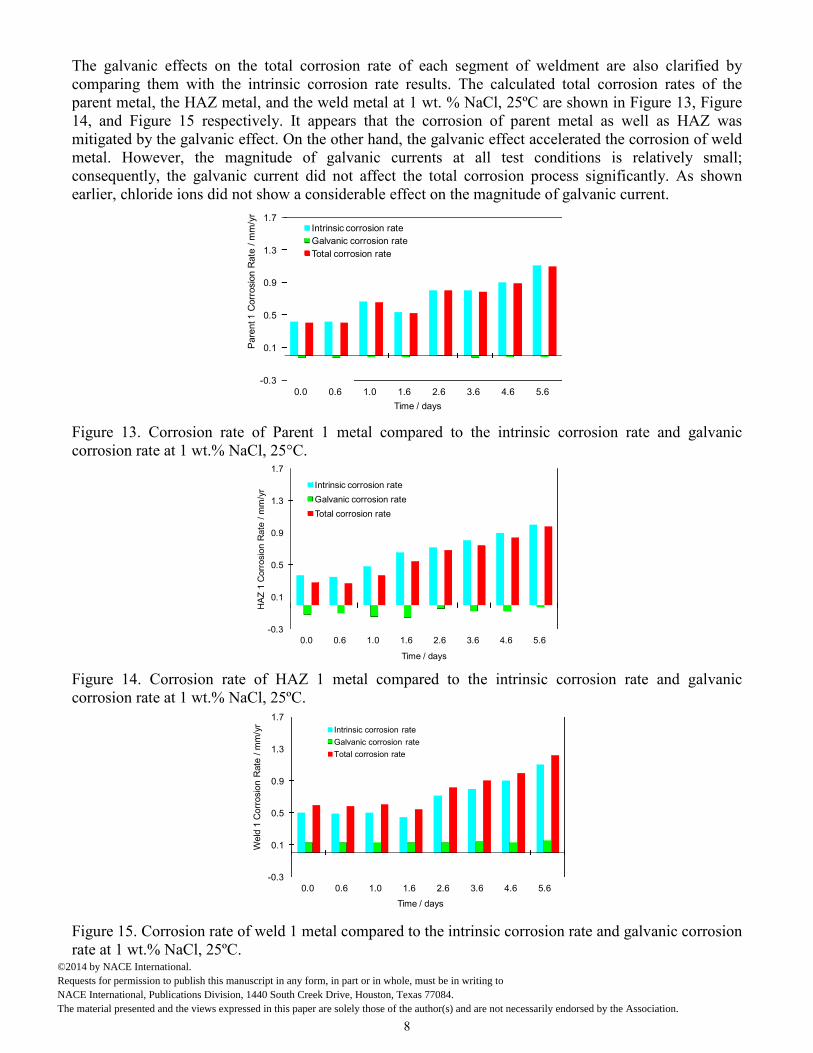
The galvanic effects on the total corrosion rate of each segment of weldment are also clarified bycomparing them with the intrinsic corrosion rate results. The calculated total corrosion rates of theparent metal, the HAZ metal, and the weld metal at 1 wt. % NaCl, 25ºC are shown in Figure 13, Figure14, and Figure 15 respectively. It appears that the corrosion of parent metal as well as HAZ wasmitigated by the galvanic effect. On the other hand, the galvanic effect accelerated the corrosion of weldmetal. However, the magnitude of galvanic currents at all test conditions is relatively small;consequently, the galvanic current did not affect the total corrosion process significantly. As shownearlier, chloride ions did not show a considerable effect on the magnitude of galvanic current.
-0.3
0.1
0.5
0.9
1.3
1.7
0.0 0.6 1.0 1.6 2.6 3.6 4.6 5.6
Pare
nt1
Corr
osi
on
Rate
/m
m/y
r
Time / days
Intrinsic corrosion rate
Galvanic corrosion rate
Total corrosion rate
Figure 13. Corrosion rate of Parent 1 metal compared to the intrinsic corrosion rate and galvaniccorrosion rate at 1 wt.% NaCl, 25°C.
-0.3
0.1
0.5
0.9
1.3
1.7
0.0 0.6 1.0 1.6 2.6 3.6 4.6 5.6
HA
Z1
Corr
osi
on
Rate
/m
m/y
r
Time / days
Intrinsic corrosion rate
Galvanic corrosion rate
Total corrosion rate
Figure 14. Corrosion rate of HAZ 1 metal compared to the intrinsic corrosion rate and galvaniccorrosion rate at 1 wt.% NaCl, 25ºC.
-0.3
0.1
0.5
0.9
1.3
1.7
0.0 0.6 1.0 1.6 2.6 3.6 4.6 5.6
Weld
1C
orr
osio
nR
ate
/m
m/y
r
Time / days
Intrinsic corrosion rate
Galvanic corrosion rate
Total corrosion rate
Figure 15. Corrosion rate of weld 1 metal compared to the intrinsic corrosion rate and galvanic corrosionrate at 1 wt.% NaCl, 25ºC.
8
©2014 by NACE International. Requests for permission to publish this manuscript in any form, in part or in whole, must be in writing to NACE International, Publications Division, 1440 South Creek Drive, Houston, Texas 77084.The material presented and the views expressed in this paper are solely those of the author(s) and are not necessarily endorsed by the Association.

Surface Analysis The specimen surface was scanned by SEM after the experiment. The surfacemorphologies of the parent, the HAZ, and the weld metal surface (with film) after different chlorideconcentration tests are shown in Figure 16, Figure 17, and Figure 18. No evidence of localized attack onany of the weldment segment surfaces was detected.
(a) Parent (b) HAZ (c) WeldFigure 16. Surface morphology (with film) of parent, HAZ, and weld after 6 days at 1 wt.% NaCl, 25ºC.
(a) Parent (b) HAZ (c) WeldFigure 17. Surface morphology (with film) of Parent, HAZ, and Weld after 6 days at 5 wt.% NaCl, 25ºC.
(a) Parent (b) HAZ (c) WeldFigure 18. Surface morphology (with film) of parent, HAZ, and weld after 6 days at 10 wt.% NaCl, 25ºC.
60°C, pH 5.0, 1bar total pressure, and 1, 5, 10 wt.% NaCl
Similar experiments were conducted at 60oC. The experimental results are shown below.
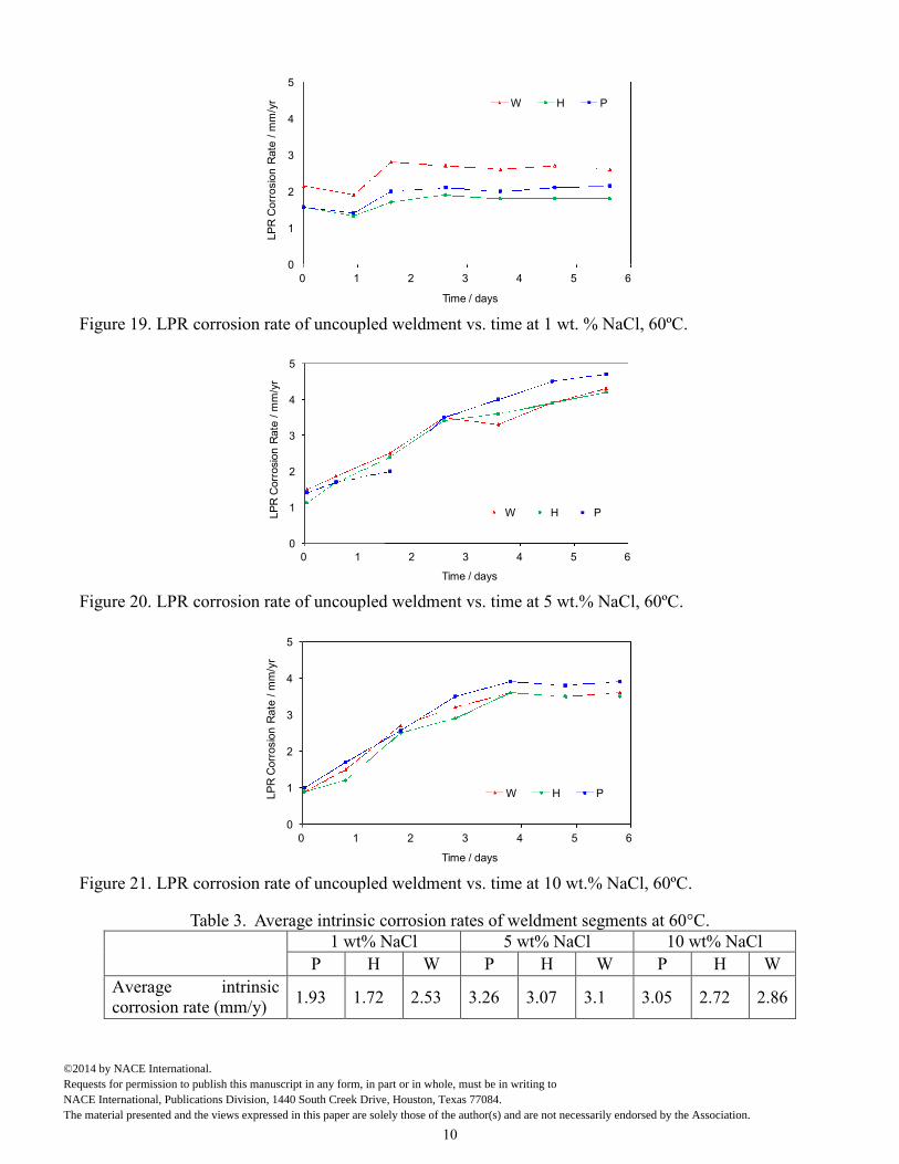
Corrosion rates The intrinsic corrosion rates of uncoupled parent, HAZ, and weld materials withtime measured by LPR at 60C, pH 5 and 1, 5 or 10 wt.% NaCl are shown in Figure 19, Figure 20, andFigure 21 respectively. The results suggest that the intrinsic corrosion rates of parent, HAZ, and weldmaterial are of the same magnitude under the same test conditions. The chloride effects on intrinsiccorrosion rate are shown in Table 3. Different from the results at 25°C, it appears that an increase ofchloride concentration from 1 wt.% to 5 wt.% at 60°C significantly increased the intrinsic corrosionrates of all segments. When the chloride concentration further increased from 5 wt.% to 10 wt.%, theacceleration of corrosion rate did not persist. The experimental results suggest that the interaction of thechloride ions with the steel surface at high temperature may be significantly different from theinteraction at low temperatures.
9
©2014 by NACE International. Requests for permission to publish this manuscript in any form, in part or in whole, must be in writing to NACE International, Publications Division, 1440 South Creek Drive, Houston, Texas 77084.The material presented and the views expressed in this paper are solely those of the author(s) and are not necessarily endorsed by the Association.
0
1
2
3
4
5
0 1 2 3 4 5 6LP
RC
orr
osio
nR
ate
/m
m/y
r
Time / days
W H P
Figure 19. LPR corrosion rate of uncoupled weldment vs. time at 1 wt. % NaCl, 60ºC.
0
1
2
3
4
5
0 1 2 3 4 5 6
LP
RC
orr
osi
on
Rate
/m
m/y
r
Time / days
W H P
Figure 20. LPR corrosion rate of uncoupled weldment vs. time at 5 wt.% NaCl, 60ºC.
0
1
2
3
4
5
0 1 2 3 4 5 6
LP
RC
orr
osio
nR
ate
/m
m/y
r
Time / days
W H P
Figure 21. LPR corrosion rate of uncoupled weldment vs. time at 10 wt.% NaCl, 60ºC.
Table 3. Average intrinsic corrosion rates of weldment segments at 60°C.1 wt% NaCl 5 wt% NaCl 10 wt% NaCl
P H W P H W P H W
Average intrinsiccorrosion rate (mm/y)
1.93 1.72 2.53 3.26 3.07 3.1 3.05 2.72 2.86
10
©2014 by NACE International. Requests for permission to publish this manuscript in any form, in part or in whole, must be in writing to NACE International, Publications Division, 1440 South Creek Drive, Houston, Texas 77084.The material presented and the views expressed in this paper are solely those of the author(s) and are not necessarily endorsed by the Association.
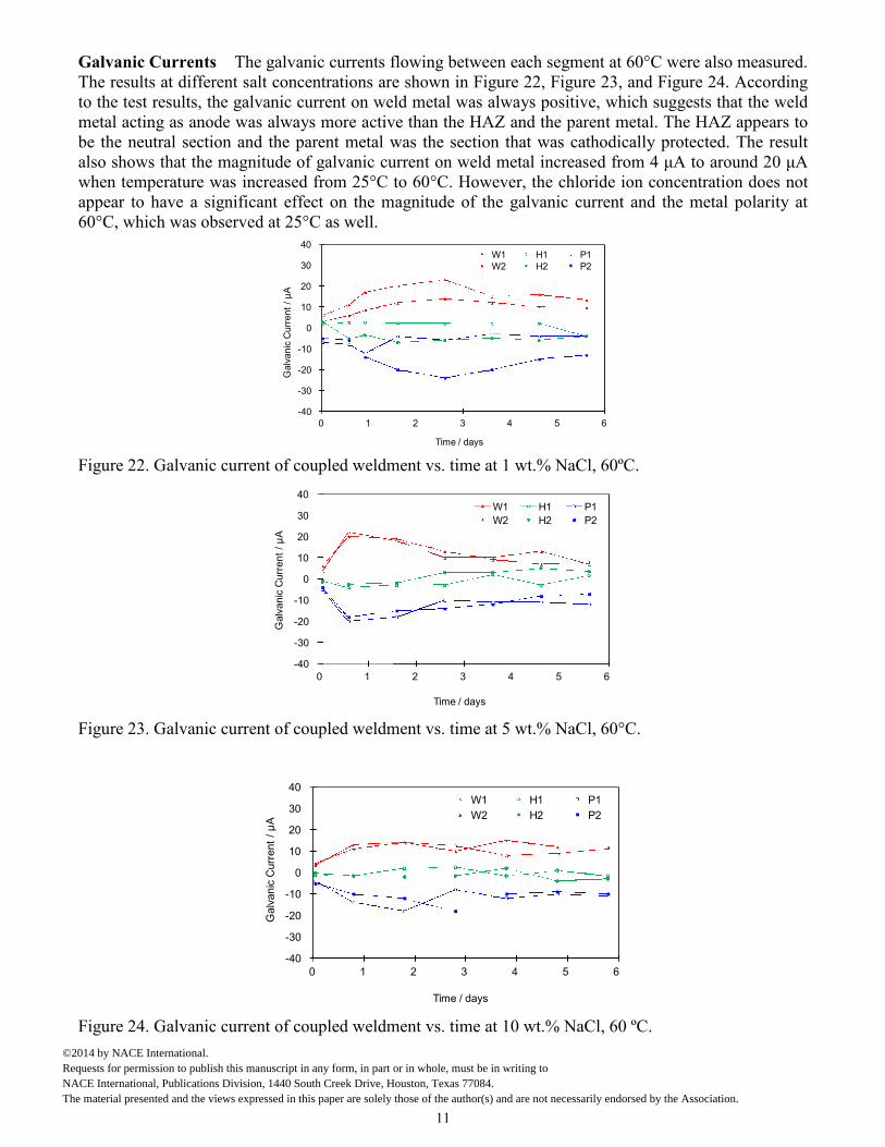
Galvanic Currents The galvanic currents flowing between each segment at 60°C were also measured.The results at different salt concentrations are shown in Figure 22, Figure 23, and Figure 24. Accordingto the test results, the galvanic current on weld metal was always positive, which suggests that the weldmetal acting as anode was always more active than the HAZ and the parent metal. The HAZ appears tobe the neutral section and the parent metal was the section that was cathodically protected. The resultalso shows that the magnitude of galvanic current on weld metal increased from 4 μA to around 20 μA when temperature was increased from 25°C to 60°C. However, the chloride ion concentration does notappear to have a significant effect on the magnitude of the galvanic current and the metal polarity at60°C, which was observed at 25°C as well.
-40
-30
-20
-10
0
10
20
30
40
0 1 2 3 4 5 6
Galv
an
icC
urr
en
t/μ
A
Time / days
W1 H1 P1W2 H2 P2
Figure 22. Galvanic current of coupled weldment vs. time at 1 wt.% NaCl, 60ºC.
-40
-30
-20
-10
0
10
20
30
40
0 1 2 3 4 5 6
Galv
anic
Curr
ent
/μ
A
Time / days
W1 H1 P1
W2 H2 P2
Figure 23. Galvanic current of coupled weldment vs. time at 5 wt.% NaCl, 60°C.
-40
-30
-20
-10
0
10
20
30
40
0 1 2 3 4 5 6
Galv
anic
Curr
ent
/μ
A
Time / days
W1 H1 P1
W2 H2 P2
Figure 24. Galvanic current of coupled weldment vs. time at 10 wt.% NaCl, 60 ºC.
11
©2014 by NACE International. Requests for permission to publish this manuscript in any form, in part or in whole, must be in writing to NACE International, Publications Division, 1440 South Creek Drive, Houston, Texas 77084.The material presented and the views expressed in this paper are solely those of the author(s) and are not necessarily endorsed by the Association.

The total corrosion rates of each segment of weldment which combines the intrinsic and the galvaniccorrosion rate at 1 wt.% NaCl and 60ºC are shown in Figure 25, Figure 26, and Figure 27. Apparently,the total corrosion rate of the parent metal was reduced by the galvanic effect. The galvanic currentsignificantly accelerated the total corrosion rata of the weld metal.
-0.5
0.5
1.5
2.5
3.5
4.5
5.5
0.0 0.6 0.9 1.6 2.6 3.6 4.6 5.6
Pare
nt1
Corr
osi
on
Rate
/m
m/y
r
Time / days
Intrinsic corrosion rate
Galvanic corrosion rate
Total corrosion rate
Figure 25. Corrosion rate of parent 1 metal compared to the intrinsic corrosion rate and galvaniccorrosion rate at 1 wt.% NaCl, 60ºC.
-0.5
0.5
1.5
2.5
3.5
4.5
5.5
0.0 0.6 0.9 1.6 2.6 3.6 4.6 5.6
HA
Z1
Corr
osi
on
Rate
/m
m/y
r
Time / days
Intrinsic corrosion rate
Galvanic corrosion rate
Total corrosion rate
Figure 26. Corrosion rate of HAZ 1 metal compared to the intrinsic corrosion rate and galvaniccorrosion rate at 1 wt.% NaCl, 60ºC.
0.0
1.0
2.0
3.0
4.0
5.0
6.0
0.0 0.6 0.9 1.6 2.6 3.6 4.6 5.6
Weld
1C
orr
osi
on
Rate
(mm
/y)
Time / days
Intrinsic corrosion rate
Galvanic corrosion rate
Total corrosion rate
Figure 27. Corrosion rate of weld 1 metal compared to the intrinsic corrosion rate and galvanic corrosionrate at 1 wt.% NaCl, 60ºC.
12
©2014 by NACE International. Requests for permission to publish this manuscript in any form, in part or in whole, must be in writing to NACE International, Publications Division, 1440 South Creek Drive, Houston, Texas 77084.The material presented and the views expressed in this paper are solely those of the author(s) and are not necessarily endorsed by the Association.
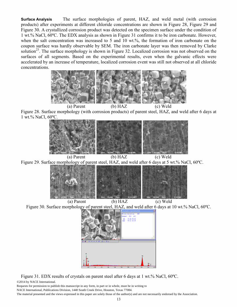
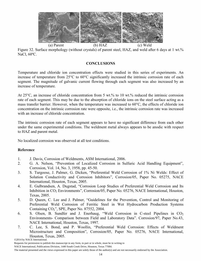
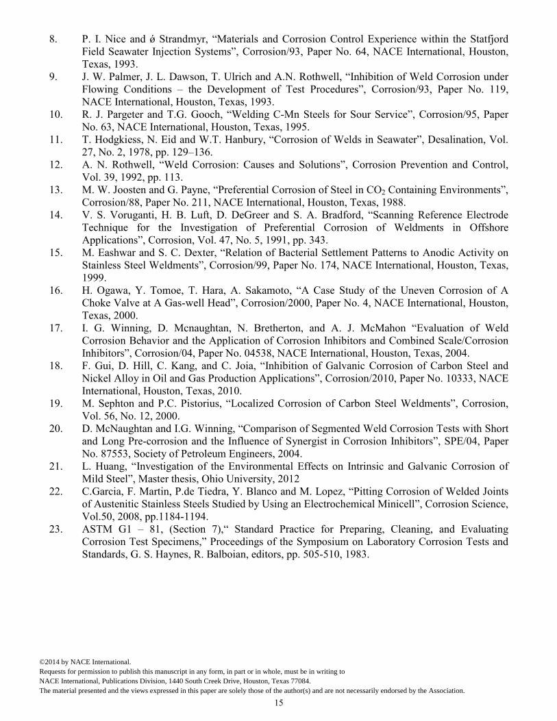
Surface Analysis The surface morphologies of parent, HAZ, and weld metal (with corrosionproducts) after experiments at different chloride concentrations are shown in Figure 28, Figure 29 andFigure 30. A crystallized corrosion product was detected on the specimen surface under the condition of1 wt.% NaCl, 60ºC. The EDX analysis as shown in Figure 31 confirms it to be iron carbonate. However,when the salt concentration was increased to 5 and 10 wt.%, the formation of iron carbonate on thecoupon surface was hardly observable by SEM. The iron carbonate layer was then removed by Clarkesolution23. The surface morphology is shown in Figure 32. Localized corrosion was not observed on thesurfaces of all segments. Based on the experimental results, even when the galvanic effects wereaccelerated by an increase of temperature, localized corrosion event was still not observed at all chlorideconcentrations.
(a) Parent (b) HAZ (c) WeldFigure 28. Surface morphology (with corrosion products) of parent steel, HAZ, and weld after 6 days at1 wt.% NaCl, 60ºC.
(a) Parent (b) HAZ (c) WeldFigure 29. Surface morphology of parent steel, HAZ, and weld after 6 days at 5 wt.% NaCl, 60ºC.
(a) Parent (b) HAZ (c) WeldFigure 30. Surface morphology of parent steel, HAZ, and weld after 6 days at 10 wt.% NaCl, 60ºC.
Figure 31. EDX results of crystals on parent steel after 6 days at 1 wt.% NaCl, 60ºC.
13
©2014 by NACE International. Requests for permission to publish this manuscript in any form, in part or in whole, must be in writing to NACE International, Publications Division, 1440 South Creek Drive, Houston, Texas 77084.The material presented and the views expressed in this paper are solely those of the author(s) and are not necessarily endorsed by the Association.
(a) Parent (b) HAZ (c) WeldFigure 32. Surface morphology (without crystals) of parent steel, HAZ, and weld after 6 days at 1 wt.%NaCl, 60ºC.
CONCLUSIONS
Temperature and chloride ion concentration effects were studied in this series of experiments. Anincrease of temperature from 25°C to 60°C significantly increased the intrinsic corrosion rate of eachsegment. The magnitude of galvanic current flowing through each segment was also increased by anincrease of temperature.
At 25°C, an increase of chloride concentration from 5 wt.% to 10 wt.% reduced the intrinsic corrosionrate of each segment. This may be due to the absorption of chloride ions on the steel surface acting as amass transfer barrier. However, when the temperature was increased to 60°C, the effects of chloride ionconcentration on the intrinsic corrosion rate were opposite, i.e., the intrinsic corrosion rate was increasedwith an increase of chloride concentration.
The intrinsic corrosion rate of each segment appears to have no significant difference from each otherunder the same experimental conditions. The weldment metal always appears to be anodic with respectto HAZ and parent metal.
No localized corrosion was observed at all test conditions.
Reference
1. J. Davis, Corrosion of Weldments, ASM International, 2006.2. G. A. Nelson, “Prevention of Localized Corrosion in Sulfuric Acid Handling Equipment”,
Corrosion, Vol. 14, No. 3, 1958, pp. 45-50.3. S. Turgoose, J. Palmer, G. Dicken, “Preferential Weld Corrosion of 1% Ni Welds: Effect of
Solution Conductivity and Corrosion Inhibitors”, Corrosion/05, Paper No. 05275, NACEInternational, Houston, Texas, 2005.
4. E. Gulbrandsen, A. Dugstad, “Corrosion Loop Studies of Preferential Weld Corrosion and ItsInhibition in CO2 Environments”, Corrosion/05, Paper No. 05276, NACE International, Houston,Texas, 2005.
5. D. Queen, C. Lee and J. Palmer, “Guidelines for the Prevention, Control and Monitoring ofPreferential Weld Corrosion of Ferritic Steel in Wet Hydrocarbon Production SystemsContaining CO2”, SPE, Paper No. 87552, 2004.
6. S. Olsen, B. Sundfer and J. Enerhaug, “Weld Corrosion in C-steel Pipelines in CO2
Environments- Comparison between Field and Laboratory Data”. Corrosion/97, Paper No.43,NACE International, Houston, Texas, 1997.
7. C. Lee, S. Bond, and P. Woollin, “Preferential Weld Corrosion: Effects of WeldmentMicrostructure and Composition”, Corrosion/05, Paper No. 05276, NACE International,Houston, Texas, 2005.
14
©2014 by NACE International. Requests for permission to publish this manuscript in any form, in part or in whole, must be in writing to NACE International, Publications Division, 1440 South Creek Drive, Houston, Texas 77084.The material presented and the views expressed in this paper are solely those of the author(s) and are not necessarily endorsed by the Association.
8. P. I. Nice and ǿ Strandmyr, “Materials and Corrosion Control Experience within the Statfjord Field Seawater Injection Systems”, Corrosion/93, Paper No. 64, NACE International, Houston,Texas, 1993.
9. J. W. Palmer, J. L. Dawson, T. Ulrich and A.N. Rothwell, “Inhibition of Weld Corrosion underFlowing Conditions – the Development of Test Procedures”, Corrosion/93, Paper No. 119,NACE International, Houston, Texas, 1993.
10. R. J. Pargeter and T.G. Gooch, “Welding C-Mn Steels for Sour Service”, Corrosion/95, PaperNo. 63, NACE International, Houston, Texas, 1995.
11. T. Hodgkiess, N. Eid and W.T. Hanbury, “Corrosion of Welds in Seawater”, Desalination, Vol.27, No. 2, 1978, pp. 129–136.
12. A. N. Rothwell, “Weld Corrosion: Causes and Solutions”, Corrosion Prevention and Control,Vol. 39, 1992, pp. 113.
13. M. W. Joosten and G. Payne, “Preferential Corrosion of Steel in CO2 Containing Environments”,Corrosion/88, Paper No. 211, NACE International, Houston, Texas, 1988.
14. V. S. Voruganti, H. B. Luft, D. DeGreer and S. A. Bradford, “Scanning Reference ElectrodeTechnique for the Investigation of Preferential Corrosion of Weldments in OffshoreApplications”, Corrosion, Vol. 47, No. 5, 1991, pp. 343.
15. M. Eashwar and S. C. Dexter, “Relation of Bacterial Settlement Patterns to Anodic Activity onStainless Steel Weldments”, Corrosion/99, Paper No. 174, NACE International, Houston, Texas,1999.
16. H. Ogawa, Y. Tomoe, T. Hara, A. Sakamoto, “A Case Study of the Uneven Corrosion of AChoke Valve at A Gas-well Head”, Corrosion/2000, Paper No. 4, NACE International, Houston,Texas, 2000.
17. I. G. Winning, D. Mcnaughtan, N. Bretherton, and A. J. McMahon “Evaluation of WeldCorrosion Behavior and the Application of Corrosion Inhibitors and Combined Scale/CorrosionInhibitors”, Corrosion/04, Paper No. 04538, NACE International, Houston, Texas, 2004.
18. F. Gui, D. Hill, C. Kang, and C. Joia, “Inhibition of Galvanic Corrosion of Carbon Steel andNickel Alloy in Oil and Gas Production Applications”, Corrosion/2010, Paper No. 10333, NACEInternational, Houston, Texas, 2010.
19. M. Sephton and P.C. Pistorius, “Localized Corrosion of Carbon Steel Weldments”, Corrosion,Vol. 56, No. 12, 2000.
20. D. McNaughtan and I.G. Winning, “Comparison of Segmented Weld Corrosion Tests with Shortand Long Pre-corrosion and the Influence of Synergist in Corrosion Inhibitors”, SPE/04, PaperNo. 87553, Society of Petroleum Engineers, 2004.
21. L. Huang, “Investigation of the Environmental Effects on Intrinsic and Galvanic Corrosion ofMild Steel”, Master thesis, Ohio University, 2012
22. C.Garcia, F. Martin, P.de Tiedra, Y. Blanco and M. Lopez, “Pitting Corrosion of Welded Jointsof Austenitic Stainless Steels Studied by Using an Electrochemical Minicell”, Corrosion Science,Vol.50, 2008, pp.1184-1194.
23. ASTM G1 – 81, (Section 7),“ Standard Practice for Preparing, Cleaning, and EvaluatingCorrosion Test Specimens,” Proceedings of the Symposium on Laboratory Corrosion Tests andStandards, G. S. Haynes, R. Balboian, editors, pp. 505-510, 1983.
15
©2014 by NACE International. Requests for permission to publish this manuscript in any form, in part or in whole, must be in writing to NACE International, Publications Division, 1440 South Creek Drive, Houston, Texas 77084.The material presented and the views expressed in this paper are solely those of the author(s) and are not necessarily endorsed by the Association.