pca-6654/6654l video display card for flat panel...
TRANSCRIPT

PCA-6654/6654LVideo Display Card for FlatPanel and CRT

ii
Part No. 2002665400
1st Edition Printed in Taiwan July 1998
Copyright Notice
This document is copyrighted by Advantech Co., Ltd. All rights arereserved. Advantech Co., Ltd. reserves the right to makeimprovements to the products described in this manual at any timewithout notice.
No part of this manual may be reproduced, copied, translated, ortransmitted in any form or by any means without the prior writtenpermission of Advantech Co., Ltd. Information provided in thismanual is intended to be accurate and reliable. However, AdvantechCo., Ltd. assumes no responsibility for its use, nor for anyinfringements upon the rights of third parties which may result fromits use.
All brand and product names mentioned herein are trademarks orregistered trademarks of their respective holders.
Warning: Do not set "V/H SYNC+Blank" in the Award BIOS ofyour CPU card.
If the Video Off Method of POWER MANAGEMENTSETUP in the Award BIOS is set on "V/HSYNC+Blank", the VGA chip 65550 on board thePCA-6654/6654L will not work properly after wokenfrom power saving mode.
iii
Packing ListBefore you set up the PCA-6654/6654L, make sure that the followingmaterials have been included with the package, and that this manual isin good condition. If anything is missing or damaged, contact yourdealer immediately:
• PCA-6654/6654L card
• PCA-6654/6654L User's Manual
• PCA-6654/6654L installation driver
Introduction
PCA-6654
This is the standard version of the video display card. It containsPanelLink features, which enables it to be used with Advantech's FPMreceiver series, including the FPM-37 and FPM-40.
PCA-6654L
This is the localized version of the video display card. It does notcontain PanelLink features. It has only one port for connection to anLCD.

iv
PCA-6654 Board Layout
PCA-6654L Board Layout
v
Additional Information and Assistance1. Visit the Advantech web sites at www.advantech.com or
www.advantech.com.tw where you can find the latest informationabout the product.
2. Contact your distributor, sales representative, or Advantech'scustomer service center for technical support if you needadditional assistance. Please have the following information ready:
• Product name and serial number
• Description of your peripheral attachments
• Description of your software (operating system, version,application software, etc.)
• Complete description of the problem
• Exact wording of any error messages

vi
Safety Instructions1. Read these safety instructions carefully.
2. Keep this user's manual for later reference.
3. Disconnect this equipment from any AC outlet before cleaning. Do not useliquid or spray detergents for cleaning. Use a damp cloth.
4. For pluggable equipment, the power outlet must be installed near theequipment and must be easily accessible.
5. Keep this equipment away from humidity.
6. Put this equipment on a reliable surface during installation. Dropping it orletting it fall could cause damage.
7. The openings on the enclosure are for air convection. Protect the equipmentfrom overheating. DO NOT COVER THE OPENINGS.
8. Make sure the voltage of the power source is correct before connecting theequipment to the power outlet.
9. Position the power cord so that people cannot step on it. Do not place anythingover the power cord.
10. All cautions and warnings on the equipment should be noted.
11. If the equipment is not used for a long time, disconnect it from the powersource to avoid damage by transient over-voltage.
12. Never pour any liquid into an opening. This could cause fire or electrical shock.
13. Never open the equipment. For safety reasons, the equipment should be openedonly by qualified service personnel.
14. If any of the following situations arises, get the equipment checked by servicepersonnel:
a. The power cord or plug is damaged.
b. Liquid has penetrated into the equipment.
c. The equipment has been exposed to moisture.
d. The equipment does not work well, or you cannot get it to work accordingto the user's manual.
e. The equipment has been dropped and damaged.
f. The equipment has obvious signs of breakage.
15. DO NOT LEAVE THIS EQUIPMENT IN AN UNCONTROLLEDENVIRONMENT WHERE THE STORAGE TEMPERATURE IS BELOW-20° C (-4° F) OR ABOVE 60° C (140° F). IT MAY DAMAGE THEEQUIPMENT.
The sound pressure level at the operator's position according to IEC 704-1:1982 isequal to or less than 70 dB(A).
DISCLAIMER: This set of instructions is given according to IEC 704-1. Advantechdisclaims all responsibility for the accuracy of any statements contained herein.
vii
Wichtige Sicherheishinweise1. Bitte lesen sie Sich diese Hinweise sorgfältig durch.
2. Heben Sie diese Anleitung für den späteren Gebrauch auf.
3. Vor jedem Reinigen ist das Gerät vom Stromnetz zu trennen. VerwendenSie Keine Flüssig-oder Aerosolreiniger. Am besten dient einangefeuchtetes Tuch zur Reinigung.
4. Die NetzanschluBsteckdose soll nahe dem Gerät angebracht und leichtzugänglich sein.
5. Das Gerät ist vor Feuchtigkeit zu schützen.
6. Bei der Aufstellung des Gerätes ist auf sicheren Stand zu achten. EinKippen oder Fallen könnte Verletzungen hervorrufen.
7. Die Belüftungsöffnungen dienen zur Luftzirkulation die das Gerät vorüberhitzung schützt. Sorgen Sie dafür, daB diese Öffnungen nichtabgedeckt werden.
8. Beachten Sie beim AnschluB an das Stromnetz die AnschluBwerte.
9. Verlegen Sie die NetzanschluBleitung so, daB niemand darüber fallenkann. Es sollte auch nichts auf der Leitung abgestellt werden.
10. Alle Hinweise und Warnungen die sich am Geräten befinden sind zubeachten.
11. Wird das Gerät über einen längeren Zeitraum nicht benutzt, sollten Sie esvom Stromnetz trennen. Somit wird im Falle einer Überspannung eineBeschädigung vermieden.
12. Durch die Lüftungsöffnungen dürfen niemals Gegenstände oderFlüssigkeiten in das Gerät gelangen. Dies könnte einen Brand bzw.elektrischen Schlag auslösen.
13. Öffnen Sie niemals das Gerät. Das Gerät darf aus Gründen derelektrischen Sicherheit nur von authorisiertem Servicepersonal geöffnetwerden.
14. Wenn folgende Situationen auftreten ist das Gerät vom Stromnetz zutrennen und von einer qualifizierten Servicestelle zu überprüfen:
a - Netzkabel oder Netzstecker sind beschädigt.
b - Flüssigkeit ist in das Gerät eingedrungen.
c - Das Gerät war Feuchtigkeit ausgesetzt.
d - Wenn das Gerät nicht der Bedienungsanleitung entsprechendfunktioni ert oder Sie mit Hilfe dieser Anleitung keine Verbesserungerzielen.
e - Das Gerät ist gefallen und/oder das Gehäuse ist beschädigt.
f - Wenn das Gerät deutliche Anzeichen eines Defektes aufweist.
Der arbeitsplatzbezogene Schalldruckpegel nach DIN 45 635 Teil 1000beträgt 70dB(A) oder weiger.
DISCLAIMER: This set of instructions is given according to IEC704-1. Advantechdisclaims all responsibility for the accuracy of any statements contained herein.

viii
Contents
Chapter 1 Introduction .................................................. 11.1 Description ..........................................................................21.2 Specifications ......................................................................31.3 Driver Support ...................................................................41.4 Utility Support ....................................................................51.5 Video BIOS .........................................................................51.6 Simultaneous Display Mode ..............................................6
Chapter 2 Hardware Setup ........................................... 72.1 Hardware Configuration ...................................................82.2 Jumpers and Connectors ...................................................9
Setting jumpers ....................................................................92.3 Jumpers, Connectors and Switches ................................102.4 Connectors for Adjuster ..................................................10
J4 ........................................................................................10J5 ........................................................................................10J9 ........................................................................................10
2.5 Board Layout - Jumpers, Connectors and Switches.....102.6 Jumper and Switch Settings ............................................12
2.6.1 LCD signal level select (J6) ......................................122.6.2 LCD bias voltage select (MONO) (J7) .....................122.6.3 LCD bias voltage select (J8) .....................................132.6.4 LCD type select (SW1) .............................................132.6.5 LCD clock configuration select (for PanelLink only) (SW2) ........................................................................142.6.6 LCD control signal configuration select (for PanelLink only) (SW3) .............................................14
2.7 LCD Setup ........................................................................152.7.1 Preliminary ................................................................152.7.2 TFT LCD Setup ........................................................162.7.3 DSTN LCD Setup .....................................................182.7.4 MONO LCD Setup ...................................................21
ix
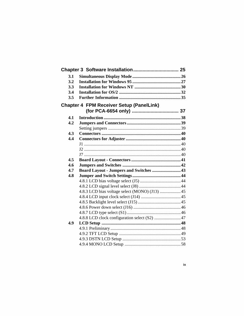
Chapter 3 Software Installation.................................. 253.1 Simultaneous Display Mode ............................................263.2 Installation for Windows 95 ............................................273.3 Installation for Windows NT ..........................................303.4 Installation for OS/2 ........................................................323.5 Further Information ........................................................35
Chapter 4 FPM Receiver Setup (PanelLink)(for PCA-6654 only) ................................... 37
4.1 Introduction ......................................................................384.2 Jumpers and Connectors .................................................39
Setting jumpers ..................................................................394.3 Connectors ........................................................................404.4 Connectors for Adjuster ..................................................40
J1 ........................................................................................40J2 ........................................................................................40J7 ........................................................................................40
4.5 Board Layout - Connectors .............................................414.6 Jumpers and Switches .....................................................424.7 Board Layout - Jumpers and Switches ..........................434.8 Jumper and Switch Settings ............................................44
4.8.1 LCD bias voltage select (J5) .....................................444.8.2 LCD signal level select (J8) ......................................444.8.3 LCD bias voltage select (MONO) (J13) ...................454.8.4 LCD input clock select (J14) ....................................454.8.5 Backlight level select (J15) .......................................454.8.6 Power down select (J16) ...........................................464.8.7 LCD type select (S1) .................................................464.8.8 LCD clock configuration select (S2) ........................47
4.9 LCD Setup ........................................................................484.9.1 Preliminary ................................................................484.9.2 TFT LCD Setup ........................................................494.9.3 DSTN LCD Setup .....................................................534.9.4 MONO LCD Setup ...................................................58

x
Appendix A Pin Assignments - PCA-6654/6654L ..... 63A.1 CRT Display (CN1) ..........................................................64A.2 Flat Panel Display (CN2) .................................................65A.3 Flat Panel Display Header (JP1) ....................................66A.4 Keyboard Connector (J3) ................................................67A.5 Backlight Power Connector (J10) ...................................67
Appendix B Pin Assignments - FPM Receiver(PanelLink) .............................................. 69
B.1 Flat Cable Panel Display Header (JP3) .........................70B.2 Flat Cable Panel Display Extension Header (JP4)........71B.3 Backlight Power (J3) ........................................................71B.4 Extension Power (J6) .......................................................71B.5 Flat Panel Display (J10) ...................................................72B.6 FFC Connector (A) For Flat Panel Display (J11) .........73B.7 FFC Connector (B) For Flat Panel Display (J12) .........74B.8 Keyboard Connector (J17) ..............................................74

Introduction
• Description
• Specifications
• Driver Support
• Utility Support
• Video BIOS
• Simultaneous Display Mode
1CHAPTER

2 PCA-6654/6654L User's Manual
1.1 DescriptionThe PCA-6654/6654L is based on the CHIPS VGA flat panel/CRTcontroller and is fully IBM VGA compatible. This controller offers alarge set of extended functions and higher resolutions, and it supportssimultaneous functioning. Since the PCA-6654/6654L VGA card isfully compatible, you do not require any special drivers to operate instandard modes. The enclosed software drivers allow you to takeadvantage of the extended features of the PCA-6654/6654L:
• High performance in Microsoft Windows
• Resolutions up to 1024 x 768 in graphics modes with 64 K colors
• 640 x 480 resolution in graphics modes with 32K, 64K, and 16Mcolors
• 132 column text mode
Warning! Be sure to turn off the power and unplug allcomponents before attempting to install or adjust thePCA-6654/6654L. Make sure the jumpers are setcorrectly before connecting the PCA-6654/6654L toyour flat panel display. Incorrect jumper settingscould damage your display.
Chapter 1 Introduction 3
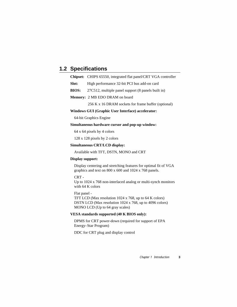
1.2 SpecificationsChipset: CHIPS 65550, integrated flat panel/CRT VGA controller
Slot: High performance 32-bit PCI bus add-on card
BIOS: 27C512, multiple panel support (8 panels built in)
Memory: 2 MB EDO DRAM on board
256 K x 16 DRAM sockets for frame buffer (optional)
Windows GUI (Graphic User Interface) accelerator:
64-bit Graphics Engine
Simultaneous hardware cursor and pop-up window:
64 x 64 pixels by 4 colors
128 x 128 pixels by 2 colors
Simultaneous CRT/LCD display:
Available with TFT, DSTN, MONO and CRT
Display support:
Display centering and stretching features for optimal fit of VGAgraphics and text on 800 x 600 and 1024 x 768 panels.
CRT -Up to 1024 x 768 non-interlaced analog or multi-synch monitorswith 64 K colors
Flat panel -TFT LCD (Max resolution 1024 x 768, up to 64 K colors)DSTN LCD (Max resolution 1024 x 768, up to 4096 colors)MONO LCD (Up to 64 gray scales)
VESA standards supported (40 K BIOS only):
DPMS for CRT power-down (required for support of EPAEnergy-Star Program)
DDC for CRT plug and display control

4 PCA-6654/6654L User's Manual
Connectors:
MDR-26 for flat panel display (PanelLink)
DB-15 for CRT
Built-in 44-pin header for Advantech standard flat panel pinassignment
Built-in housing to connect VR for adjusting contrast/brightness
Power:
On-board DC-DC converter supplies LCD bias voltage
LCD backlight power supplied
PanelLink:
High speed and low EMI operation
Flexible panel interface
1.3 Driver SupportThe software driver provides for the following systems:
Software Name of VGA Driver Disk
MicrosoftWindows 95 PCA-6654 VGA Driver Windows 95 & NT 4.0
MicrosoftWindows NT 4.0 PCA-6654 VGA Driver Windows 95 & NT 4.0
IBM OS/2 PCA-6654 VGA Driver OS/2

Chapter 1 Introduction 5
1.4 Utility SupportThe utility provides:
CT.COM Enable CRT display only
FP.COM Enable panel display only
SM.COM Enable both displays at the same time
REVERSE.EXE Reverse the displays' colors
READBIOS.EXE Read the VGA BIOS information
TESTDDC.EXE Test if the VGA BIOS supports DDC
These utilities are only supported in DOS mode, and can only be usedfor testing.
1.5 Video BIOSThe standard BIOS chip supports eight kinds of flat panel displays:
1024 x 768 DSTN (Sharp LM14X82)
640 x 480 MONO (Sharp LM64P89)
640 x 480 DSTN (Kyocera KCB6448BSTT-X5)
800 x 600 DSTN
640 x 480 SHARP TFT
640 x 480 18-bit TFT (Toshiba LTM10C209A)
1024 x 768 TFT
800 x 600 TFT (Toshiba LTM10C273)
Note 1: To program the VGA BIOS to support the LCD only,you must use the file "6654-STN.DAT" located on theutility disk.
Note 2: The Chips 65550 chipset cannot support a 1024 x768 DSTN LCD on SM mode, due to bandwidthproblems.

6 PCA-6654/6654L User's Manual
1.6 Simultaneous Display ModeThe PCA-6654/6654L supports simultaneous display to a CRTmonitor and a flat panel display. The flat panel may be TFT, DSTN orMONO.
If you use a DSTN LCD in this mode, the display must be under16/256 colors or the CRT and flat panel screens will tremble. Youmust add a frame buffer with 512 K RAM and update the BIOS setup.Call us for assistance.

Hardware Setup
• Hardware Configuration
• Jumpers and Connectors
• Jumpers, Connectors and Switches
• Connectors for Adjuster
• Board Layout - Jumpers, Connectors andSwitches
• Jumper and Switch Settings
• LCD Setup
- Preliminary
- TFT LCD Setup
- DSTN LCD Setup
- MONO LCD Setup
2CHAPTER

8 PCA-6654/6654L User's Manual
2.1 Hardware ConfigurationThe PCA-6654/6654L is based on chipset 65550 and has highperformance, a simple configuration, and fully supported LCD/CRT.
Figure 2-1: System block diagram
65550
2 M B V i d e oM e m o r y
5 1 2 K BFrame Bu f fe r
B I O S
C R TDisp lay
Power -onsequenc ing &
D C - D CConve r te r
F la t PanelD isp lay
Pane l L inkTransmi t te rS i I 100 /140
Pane l L inkRece ive r
S i I 101 /141
Address
Da ta
Cont ro l
Address Data
Address Data Address Data
32-B i tPC I Bus
R G BH/V Sync
DDC CLK/Data
E N A V E EE N A V D D
Panel Data
Panel Control
V D D S A F E V E E S A F E
Flat PanelD isp lay
Data Pa i r sCLK Pa i r
D a t a Con t ro l
L C D M o n i t o r
32
32
816
8 832 16
24
3
24/36
Chapter 2 Hardware Setup 9
2.2 Jumpers and Connectors
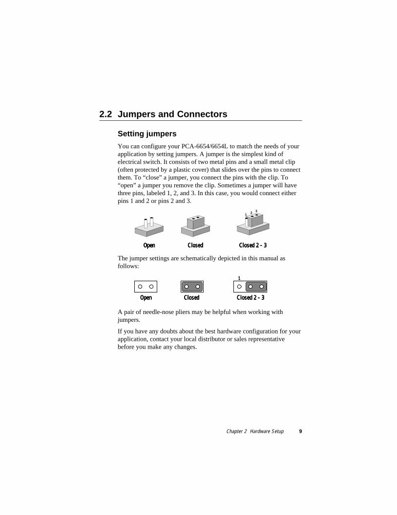
Setting jumpers
You can configure your PCA-6654/6654L to match the needs of yourapplication by setting jumpers. A jumper is the simplest kind ofelectrical switch. It consists of two metal pins and a small metal clip(often protected by a plastic cover) that slides over the pins to connectthem. To “close” a jumper, you connect the pins with the clip. To“open” a jumper you remove the clip. Sometimes a jumper will havethree pins, labeled 1, 2, and 3. In this case, you would connect eitherpins 1 and 2 or pins 2 and 3.
The jumper settings are schematically depicted in this manual asfollows:
A pair of needle-nose pliers may be helpful when working withjumpers.
If you have any doubts about the best hardware configuration for yourapplication, contact your local distributor or sales representativebefore you make any changes.
132
OpenOpenOpenOpenOpen ClosedClosedClosedClosedClosed Closed 2 - 3Closed 2 - 3Closed 2 - 3Closed 2 - 3Closed 2 - 3
1
OpenOpenOpenOpenOpen ClosedClosedClosedClosedClosed Closed 2 - 3Closed 2 - 3Closed 2 - 3Closed 2 - 3Closed 2 - 3

10 PCA-6654/6654L User's Manual
2.3 Jumpers, Connectors and Switches
Table 2-1: Jumpers, connectors, switches and their functions
Label FunctionCN1 CRT displayCN2 Flat panel displayJP1 Flat panel display headerJ3 Keyboard connectorJ10 Backlight power connectorJ4 DSTN LCD contrast adjustmentJ5 MONO LCD contrast adjustmentJ9 LCD brightness adjustmentJ6 LCD signal level selectJ7 LCD bias voltage select (MONO)J8 LCD bias voltage selectSW1 LCD type selectSW2 LCD clock configuration select (for PanelLink only)SW3 LCD control signal configuration select (for PanelLink only)
Please refer to Appendix A for pin assignments.
2.4 Connectors for Adjuster
J4
This is a 3-pin housing. Connect a 500 Ω external VR to adjust VCON
;voltage range 0 ~ +2.8 V.
J5
This is a 2-pin housing. Connect a 500 Ω external VR with on-boardR-23 to adjust V
EE; voltage range +5 ~ +40 V or 0 ~ -40 V,
depending on the jumper setting.
J9
This is a 3-pin housing. Connect a 500 Ω external VR to adjust VBR
;voltage range 0 ~ +4.3 V.

Chapter 2 Hardware Setup 11
Figure 2-2: Board layout - jumpers, connectors and switches
2.5 Board Layout - Jumpers, Connectors andSwitches
J8: LCD biasvoltage select
CN2: Flat paneldisplay
J3: Keyboardconnector
CN1: CRT display
SW3: LCD controlsignal configurationselect
J7: LCD bias voltageselect (MONO)
J5: MONO LCDcontrast
adjustment
J6: LCD signallevel select
J9: LCDbrightnessadjustment
JP1: Flat paneldisplay header
SW1: LCD typeselect
SW2: LCD clockconfiguration select
J4: DSTN LCDcontrast
adjustment
J10: Backlightpower
connector

12 PCA-6654/6654L User's Manual
2.6 Jumper and Switch SettingsBe sure the jumper and switch settings are correct before you installthe card to the chassis. Refer to Fig. 2-2 for jumper and switchlocations.
For information about installing an LCD into your system, refer toSection 2. (LCD Setup) or Chapter 4 (FPM Receiver Setup) of thismanual.
2.6.1 LCD signal level select (J6)
Table 4-4: LCD signal level select (J6)
* 5 V 3.3 V
* default setting
2.6.2 LCD bias voltage select (MONO) (J7)
Table 4-5: LCD bias voltage select (MONO) (J7)
+VEE [+5 V ~ +40 V] * -VEE [0 V ~ -40 V]
* default setting
1 1
1 1

Chapter 2 Hardware Setup 13
2.6.3 LCD bias voltage select (J8)
Table 4-3: LCD bias voltage select (J8)
VEE [+5 ~ +40 V or 0 ~ -40 V for MONO LCD]
* VCON [0 ~ +2.8 V for DSTN LCD]
* default setting
2.6.4 LCD type select (SW1)
Table 2-5: LCD type select (SW1)
LCD type Pin 1 Pin 2 Pin 3 Pin 4* 640 x 480 18-bit TFT OFF ON OFF ON640 x 480 SHARP TFT ON ON OFF ON800 x 600 TFT OFF OFF OFF ON1024 x 768 TFT ON OFF OFF ON640 x 480 DSTN ON OFF ON ON800 x 600 DSTN OFF OFF ON ON1024 x 768 DSTN ON ON ON ON640 x 480 MONO OFF ON ON ON
* default setting
1
1

14 PCA-6654/6654L User's Manual
2.6.5 LCD clock configuration select (forPanelLink only) (SW2)
Table 2-6: LCD clock configuration select (forPanelLink only) (SW2)
LCD type Pin 1 Pin 2 Pin 3 Pin 4* TFT ON OFF ON OFF640 x 480 DSTN OFF ON OFF ON800 x 600 DSTN OFF ON OFF ON1024 x 768 DSTN ON OFF OFF ON640 x 480 MONO ON OFF ON OFF
* default setting
2.6.6 LCD control signal configuration select (forPanelLink only) (SW3)
Table 2-7: LCD control signal configuration select (for PanelLinkonly) (SW3)
Pin number and setting details1 * The LCD input data are latched on falling edge of clock → ON
The LCD input data are latched on rising edge of clock → OFF2 * The LCD control signals are latched on falling edge of clock → ON
The LCD control signals are latched on rising edge of clock → OFF3 The SiI100 differential clock output is divided by two → ON
* The SiI100 differential clock output is divided by one → OFF
* default setting

Chapter 2 Hardware Setup 15
2.7 LCD Setup
2.7.1 Preliminary
Make sure that your LCD is ready to match your PCA-6654/6654Lcard prior to setting jumpers and switches. You will need to knowyour LCD specifications, which will be among the following:
1. LCD type: TFT, DSTN or MONO
2. Number of pixels:640 x 480, 800 x 600 or 1024 x 768 respectively
3. Supply voltage: 5 V or 3.3 V
4. LCD bias voltage for DSTN or MONO: Vmin., Vtyp., Vmax.
5. Backlight brightness voltage range in inverter
You must also have the following parts ready:
1. LCD cable, to connect the LCD to JP1
2. Inverter, which must match your LCD specifications
3. Inverter power wire, to connect the inverter to J10
4. 500 Ω VR assembly with wire, for adjusting brightness
5. 500 Ω VR assembly with wire, for adjusting contrast (DSTN orMONO LCD only)
Note: If your DSTN LCD does not have a built-in DC/DCconverter, your must set up your LCD according tothe MONO LCD setup procedures, except for whenyou set up SW1.

16 PCA-6654/6654L User's Manual
2.7.2 TFT LCD Setup
Follow these steps:
1. Set SW1 according to the following table:
Table 2-8: TFT LCD setup (SW1)
LCD type Pin 1 Pin 2 Pin 3 Pin 4* 640 x 480 18-bit TFT OFF ON OFF ON640 x 480 SHARP TFT ON ON OFF ON800 x 600 TFT OFF OFF OFF ON1024 x 768 TFT ON OFF OFF ON
* default setting
2. Set SW2 as follows, for all TFT LCDs:
LCD type Pin 1 Pin 2 Pin 3 Pin 4All TFT types ON OFF ON OFF
3. You do not need to set SW3.
4. Set J6 according to your LCD input power specifications:
Table 2-9: LCD signal level select (J6)
* 5 V 3.3 V
* default setting
5. You do not need to set J7 or J8.
6. Connect the LCD cable, inverter, inverter power wire, and VRassembly with wire to J9. (See Fig. 2-3.)
7. Plug the VGA card into the PCI slot.
8. Power on the system.
9. Adjust the screen brightness using the VR control.
1
2
3
11
2
3

Chapter 2 Hardware Setup 17
Figure 2-3: TFT LCD setup
Brig
htne
ss V
R
LCD
cab
le
Inve
rter
pow
er w
ire
PC
A-6
654/
6654
L
Inverter

18 PCA-6654/6654L User's Manual
2.7.3 DSTN LCD Setup
Follow these steps:
1. Set SW1 according to the following table:
Table 2-10: DSTN LCD setup (SW1)
LCD type Pin 1 Pin 2 Pin 3 Pin 4640 x 480 DSTN ON OFF ON ON800 x 600 DSTN OFF OFF ON ON1024 x 768 DSTN ON ON ON ON
2. Set SW2 as follows, for all DSTN LCDs:
LCD type Pin 1 Pin 2 Pin 3 Pin 4All DSTN types ON OFF ON OFF
3. You do not need to set SW3.
4. Set J6 according to your LCD input power specifications:
Table 2-11: LCD signal level select (J6)
* 5 V 3.3 V
* default setting
5. You do not need to set J7.
11
2
3
1
2
3

Chapter 2 Hardware Setup 19
6. Set J8 as follows:
Table 2-12: LCD bias voltage select (J8)
VCON
7. Connect the LCD cable, inverter, inverter power wire, and VRassembly. The VR assembly with wire for brightness controlshould be connected to J9, and the wire for contrast controlshould be connected to J4. (See Fig. 2-4.)
8. Plug the VGA card into the PCI slot.
9. Power on the system.
10. Adjust the screen brightness and contrast using the VR controls.
11
2
3

20 PCA-6654/6654L User's Manual
Figure 2-4: DSTN LCD setup
Brig
htne
ss V
R
LCD
cab
le
Inve
rter
pow
er w
ire
PC
A-6
654/
6654
L
Inverter
Con
tras
t VR

Chapter 2 Hardware Setup 21
2.7.4 MONO LCD Setup
Follow these steps:
1. Set SW1 as follows:
LCD type Pin 1 Pin 2 Pin 3 Pin 4640 x 480 MONO OFF ON ON ON
2. Set SW2 as follows:
LCD type Pin 1 Pin 2 Pin 3 Pin 4640 x 480 MONO ON OFF ON OFF
3. You do not need to set SW3.
4. Set J6 according to your LCD input power specifications:
Table 2-13: LCD signal level select (J6)
* 5 V 3.3 V
* default setting
5. Set J7 as follows:
Table 2-14: LCD bias voltage select (MONO) (J7)
+VEE -VEE
1
2
3
11
2
3
1
2
3
11
2
3

22 PCA-6654/6654L User's Manual
6. Set J8 as follows:
Table 2-15: LCD bias voltage select (J8)
VEE
7. Plug the VGA card into the PCI slot.
8. Short J5.
9. Power on the system.
10. Adjust R-23 to be VEE
max.
11. Power off the system.
12. Remove the jumper on J5.
13. Connect the LCD cable, inverter, inverter power wire, and VRassembly. The VR assembly with wire for brightness controlshould be connected to J9, and the wire for contrast controlshould be connected to J5. (See Fig. 2-5.)
14. Power on the system.
15. Adjust the screen brightness and contrast using the VR controls.
1
2
3

Chapter 2 Hardware Setup 23
Figure 2-5: MONO LCD setup
Brig
htne
ss V
R
LCD
cab
le
Inve
rter
pow
er w
ire
PC
A-6
654/
6654
L
Inverter
Con
tras
t VR

24 PCA-6654/6654L User's Manual

Software Installation
This chapter describes the installation andoperation of the software drivers on thedisplay driver diskettes included in yourPCA-6654/6654L package. Sections in thischapter include:
• Simultaneous Display Mode
• Installation for Windows 95
• Installation for Windows NT
• Installation for OS/2
• Further Information
3CHAPTER

26 PCA-6654/6654L User's Manual
3.1 Simultaneous Display ModeThe 65550 VGA BIOS supports color TFT, color DSTN andmonochrome LCD flat panel displays. It also supports interlaced andnon-interlaced analog monitors (VGA color and VGA monochrome)in high-resolution modes while maintaining complete IBM VGAcompatibility. Digital monitors (i.e. MDA, CGA, and EGA) are NOTsupported. Multiple frequency (multisync) monitors are supported asanalog monitors.
Both CRT and panel displays can be used simultaneously. ThePCA-6654/6654L can be set in one of three configurations: on a CRT,on a flat panel display, or on both simultaneously. The system isinitially set to simultaneous display mode. In the utility diskettes,there are three .COM files which can be used to select the display.Simply type the file name at the DOS prompt:
CT.COM Enables CRT display only
FP.COM Enables panel display only
SM.COM Enables both displays at the same time

Chapter 3 Software Drivers and Utilities 27
3.2 Installation for Windows 95
a. Select "Start" , "Sett ings" , "Control Panel".b. Double cl ick the "display" icon.c. Choose the "Sett ings " label.d . Press the "Advanced Propert ies" button.
a. Choose the "Adapter" label.b. Press the "Change.. . " button.
a. Press the "Have Disk. . . " button.
a. Insert the "VGA Driver Windows 95&NT 4.0" disk into the f loppy driver.b. Type "A: \WIN95P.244".c. Press the "OK" but ton.
1.
2.
3.
4.

28 PCA-6654/6654L User's Manual
a. Press the "OK" button.
a. "Ch ips and Tech 65550PCI" appear in the Adapter label .b. Press the "Close" button.
a. Press the "Yes" buttonb. Close al l windows to reboot
a. Repeat Step 1 on the previous page of this manual.b. The "Chips" label appears in "Display Propert ies".c. Adjust the resolut ion and color.
5.
6.
7.
8.

Chapter 3 Software Drivers and Utilities 29
a. Choose the "Chips" label .b. Adjust the refresh rate and display device.c. Press the "OK" but ton
a. Press the "OK" button to change the display sett ing.
a. Press the "OK" button to confirm the sett ing.
E N D
9.
10.
11.

30 PCA-6654/6654L User's Manual
3.3 Installation for Windows NT
a. Press the "Change. . . " button.
a. Press the "Have Disk. . . " button.
a. Inser t the "VGA Dr iver Windows 95&NT 4 .0" disk into the f loppy dr iver.b . Type "A: \WINNT4.115" .c . Press the "OK" but ton.
a. Select "Start" , "Sett ings" , "Control Panel" .b. Double c l ick the "display" icon.c. Choose the "Set t ings " label.d. Press the "Display Type" button.
1.
2.
3.
4.

Chapter 3 Software Drivers and Utilities 31
a. Press the "OK" button.
a. Press the "Yes" button
a. Press the "OK" but tonb. Close al l windows to reboot
a. Repeat Step 1 on the previous page of this manual.b. The "Chips" label appears in "Display Propert ies".c. Adjust the resolut ion, color and refresh rate.d. Press the "Test" button to check the sett ing.e. Press the "OK" button to confirm the sett ing.
END
5.
6.
7.
8.

32 PCA-6654/6654L User's Manual
3.4 Installation for OS/2
a. Select "OS/2 System" , "Command Prompts" , "OS/2 Window".b. Insert the "VGA Driver OS/2" disk into the f loppy driver.c. Type"A:",<Enter>.d. Type"setup A: C:" ,<Enter>.
a. Press the "OK" button to shut down.b. Reboot again.
a. Select "OS/2 System", "System Setup", "Display Driver Install".b. Enable "Primary Display".c. Press the "OK" button.
a. Select "Chips & Technologies 65550/554/555".b. Press the "OK" button.
1.
2.
3.
4.

Chapter 3 Software Drivers and Utilities 33
a. Select "Instal l Using Defaults for Monitor Type".b. Press the "OK" button.
a. Type "A:\" .b. Press the "Instal l . . ." button.
a. Insert the "VGA Driver OS/2" disk into the f loppy driver.b. Press the "OK" button.
a. Press the "OK" button to shut down and restart the system.
5.
6.
7.
8.

34 PCA-6654/6654L User's Manual
a. Select "OS/2 System", "System Setup", "System".
a. Select the "Screen" tab.b. Adjust the resolut ion, color and refresh rate.
E N D
9.
10.

Chapter 3 Software Drivers and Utilities 35
3.5 Further InformationFor further information about installation of the PCI/SVGA in yourPCA-6654/6654L, including driver updates, troubleshooting guidesand FAQ lists, visit the following web resources:
C&T web site: www.chips.com
Advantech web sites:www.advantech.com
www.advantech.com.tw

36 PCA-6654/6654L User's Manual

FPM Receiver Setup(PanelLink)(for PCA-6654 only)
• Introduction
• Jumpers and Connectors
• Connectors
• Connectors for Adjuster
• Board Layout - Connectors
• Jumpers and Switches
• Board Layout - Jumpers and Switches
• Jumper and Switch Settings
• LCD Setup
- Preliminary
- TFT LCD Setup
- DSTN LCD Setup
- MONO LCD Setup
4CHAPTER

38 PCA-6654/6654L User's Manual
4.1 IntroductionThe SiI100/140 (added into the PCA-6654) and SiI101/141 (addedinto the FPM-40 receiver) are high-speed digital video/graphicsinterconnection devices capable of supporting VGA to XVGAresolutions for TFT panels and VGA to XGA resolutions for DSTNLCD panels. These devices are based on Silicon Image's PanelLinktechnology that currently enables reliable, scalable, high-speed datatransmission over the same interface, from VGA to SVGA resolutions(and up to HDTV resolution in the future). The PanelLink transmitterincorporates an advanced coding scheme to enable TMDS signals toreduce EMI across copper cables and DC-balancing for datatransmission over fiber optics. In addition, the advanced codingscheme enables robust clock recovery at the receiver to achievehigh-skew tolerance for driving longer cable lengths. To maximizedata recovery accuracy, the receiver triple oversamples and makes useof a data recovery algorithm to select the most reliable data samplingpoints.

Chapter 4 FPM Receiver Setup (PanelLink) (for PCA-6654 only) 39
4.2 Jumpers and Connectors
Setting jumpers
You can configure your FPM card to match the needs of yourapplication by setting jumpers. A jumper is the simplest kind ofelectrical switch. It consists of two metal pins and a small metal clip(often protected by a plastic cover) that slides over the pins to connectthem. To “close” a jumper, you connect the pins with the clip. To“open” a jumper you remove the clip. Sometimes a jumper will havethree pins, labeled 1, 2, and 3. In this case, you would connect eitherpins 1 and 2 or pins 2 and 3.
The jumper settings are schematically depicted in this manual asfollows:
A pair of needle-nose pliers may be helpful when working withjumpers.
If you have any doubts about the best hardware configuration for yourapplication, contact your local distributor or sales representativebefore you make any changes.
132
OpenOpenOpenOpenOpen ClosedClosedClosedClosedClosed Closed 2 - 3Closed 2 - 3Closed 2 - 3Closed 2 - 3Closed 2 - 3
1
OpenOpenOpenOpenOpen ClosedClosedClosedClosedClosed Closed 2 - 3Closed 2 - 3Closed 2 - 3Closed 2 - 3Closed 2 - 3

40 PCA-6654/6654L User's Manual
4.3 Connectors
Table 4-1: Connectors
Label FunctionJP3 Flat cable panel display headerJP4 Flat cable panel display extension headerJ3 Backlight powerJ6 Extension powerJ10 Flat panel display connectorJ11 FFC connector (A) for flat panel displayJ12 FFC connector (B) for flat panel displayJ17 Keyboard connectorJ1 MONO LCD contrast adjustmentJ2 Brightness adjustmentJ7 DSTN LCD contrast adjustment
Please refer to Appendix B for pin assignments.
4.4 Connectors for Adjuster
J1
This is a 2-pin housing. Connect a 500 Ω external VR with on-boardVR1 to adjust V
EE SAFE; voltage range +5 ~ +40 V and 0 ~ -40 V.
J2
This is a 3-pin housing. Connect a 500 Ω external VR to adjust VBR
;voltage range 0 ~ +4.3 V.
J7
This is a 3-pin housing. Connect a 500 Ω external VR to adjust VEE
SAFE; voltage range 0 ~ +2.8 V.

Chapter 4 FPM Receiver Setup (PanelLink) (for PCA-6654 only) 41
4.5 Board Layout - Connectors
Figure 4-1: Board layout - connectors
J17: Keyboardconnector
J1: MONO LCDcontrastadjustment
J7: DSTN LCDcontrastadjustment
J11: FCCconnector (A)for flat paneldisplay
J12: FCCconnector (B)for flat paneldisplay
JP3: Flat cablepanel display
JP4: Flat cablepanel displayextension
J3: Backlight power
J2: Brightnessadjustment
J6: Extensionpower
J10: Flatpanel display
connector

42 PCA-6654/6654L User's Manual
4.6 Jumpers and Switches
Table 4-2: Jumpers and switches
Label FunctionJ5 LCD bias voltage selectJ8 LCD signal level selectJ13 LCD bias voltage select (MONO)J14 LCD input clock selectJ15 Backlight level selectJ16 Power down selectS1 LCD type selectS2 LCD clock configuration select

Chapter 4 FPM Receiver Setup (PanelLink) (for PCA-6654 only) 43
4.7 Board Layout - Jumpers and Switches
Figure 4-3: Board layout - jumpers and switches
J14: LCD inputclock select
J8: LCD signallevel select
J13: LCD biasvoltage select(MONO)
J5: LCD bias voltageselect
S2: LCD clockconfigurationselect
J16: Powerdown select
J15: Backlightlevel select
S1: LCD typeselect

44 PCA-6654/6654L User's Manual
4.8 Jumper and Switch SettingsMake sure the jumper and switch settings are correct before youinstall the FPM card to the chassis. Please refer to Appendix B for pinassignments.
4.8.1 LCD bias voltage select (J5)
Table 4-3: LCD bias voltage select (J5)
VEE [+5 ~ +40 V or 0 ~ -40 V for MONO LCD]
* VCON [0 ~ +2.8 V for DSTN LCD]
* default setting
4.8.2 LCD signal level select (J8)
Table 4-4: LCD signal level select (J8)
* 5 V 3.3 V
* default setting
1
1
1 1

Chapter 4 FPM Receiver Setup (PanelLink) (for PCA-6654 only) 45
4.8.3 LCD bias voltage select (MONO) (J13)
Table 4-5: LCD bias voltage select (MONO) (J13)
+VEE [+5 V ~ +40 V] * -VEE [0 V ~ -40 V]
* default setting
4.8.4 LCD input clock select (J14)
Table 4-6: LCD input clock select (J14)
* Divided by one Divided by two
* default setting
4.8.5 Backlight level select (J15)
Table 4-7: Backlight level select (J15)
* ENAVEE [high level] /ENAVEE [low level]
* default setting
1 1
1 1
1 1

46 PCA-6654/6654L User's Manual
4.8.6 Power down select (J16)
Table 4-8: Power down select (J16)
Power down * Normal
* default setting
4.8.7 LCD type select (S1)
Table 4-9: LCD type select (S1)
LCD type Pin 1 Pin 2 Pin 3 Pin 4* 640 x 480 DSTN ON OFF OFF OFF800 x 600 DSTN ON OFF OFF OFF1024 x 768 DSTN OFF ON OFF OFFTFT OFF OFF ON OFF
* default setting

Chapter 4 FPM Receiver Setup (PanelLink) (for PCA-6654 only) 47
4.8.8 LCD clock configuration select (S2)
Table 4-10: LCD clock configuration select (S2)
Pin Pin Pin PinLCD type Frequency/data latch edge/mode 1 2# 3 4* TFT/16-bit DSTN divided by 1/negative/free running ON X ON ONTFT/16-bit DSTN divided by 1/positive/free running ON X OFF ONTFT divided by 2/negative/free running OFF X ON ONTFT divided by 2/positive/free running OFF X OFF ON24-bit DSTN divided by 1/negative/blanked low ON X ON OFFNONE divided by 1/negative/blanked high ON X OFF OFF24-bit DSTN divided by 2/negative/blanked low OFF X ON OFF24-bit DSTN divided by 4/negative/blanked low OFF X OFF OFF
* default setting
# Termination resistor range selection:
ON: 55 ~ 70 Ω
OFF: 40 ~ 57 Ω (default)

48 PCA-6654/6654L User's Manual
4.9 LCD Setup
4.9.1 Preliminary
Before you set the jumpers and switches, you need to know the LCDspecifications, which will be among the following:
1. LCD type: TFT, DSTN or MONO
2. Number of pixels: 640 x 480, 800 x 600 or 1024 x 768 respectively
3. One pixel per clock or two pixels per clock in TFT LCD
4. LCD input data and control signals are latched on falling or risingedge
5. Supply voltage: 5 V or 3.3 V
6. LCD bias voltage for DSTN or MONO LCD: Vmin., Vtyp.,Vmax.
7. Backlight brightness voltage range in inverter.
You should also have:
1. PanelLink cable (refer to J10 and PCA-6654 CN2)
2. LCD cable (refer to LCD, JP3/JP4 or J11/J12 pin assignments)
3. Inverter (refer to LCD specifications)
4. Inverter power wire (refer to inverter and J3)
5. VR 500 Ω assembly with wire for adjusting brightness
6. VR 500 Ω assembly with wire for adjusting contrast (for DSTNor MONO LCD)
Note: If your DSTN LCD does not have a built-in DC/DCconverter, your must set up your LCD according tothe MONO LCD setup procedures, except for whenyou set up SW1.

Chapter 4 FPM Receiver Setup (PanelLink) (for PCA-6654 only) 49
4.9.2 TFT LCD Setup
Follow these steps:
PCA-66541. Set SW1 according to the following table:
Table 4-11: TFT LCD setup (SW1)
LCD type Pin 1 Pin 2 Pin 3 Pin 4640 x 480 18-bit TFT OFF ON OFF ON640 x 480 SHARP TFT ON ON OFF ON800 x 600 TFT OFF OFF OFF ON1024 x 768 TFT ON OFF OFF ON
2. Set SW2 as follows, for all TFT LCDs:
LCD type Pin 1 Pin 2 Pin 3 Pin 4All TFT types ON OFF ON OFF
3. Set SW3 according to the following table:
Table 4-12: LCD control configuration select (SW3)
ON OFF1 DATA EDGE Falling edge Rising edge2 CLOCK EDGE Falling edge Rising edge3 HALF CLOCK Divided by two Divided by one
4. You do not need to set J6, J7 and J8.
FPM Receiver5. Set S1 as follows, for all TFT LCDs:
LCD type Pin 1 Pin 2 Pin 3 Pin 4All TFT types OFF OFF ON OFF

50 PCA-6654/6654L User's Manual
6. Set S2 according to the following table:
Table 4-13: LCD clock configuration select (S2)
Frequency/data latch edge/mode Pin 1 Pin 2# Pin 3 Pin 4divided by 1/negative/free running ON X ON ONdivided by 1/positive/free running ON X OFF ONdivided by 2/negative/free running OFF X ON ONdivided by 2/positive/free running OFF X OFF ON
# Termination resistor range selection:
ON: 55 ~ 70 Ω
OFF: 40 ~ 57 Ω (default)
7. You do not need to set J5.
8. Set J8 as follows:
Table 4-14: LCD signal level select (J8)
* 5 V 3.3 V
* default setting
9. You do not need to set J13.
10. Set J14 as follows:
Table 4-15: LCD input clock select (J14)
* Divided by one Divided by two
* default setting
1 1
1 1

Chapter 4 FPM Receiver Setup (PanelLink) (for PCA-6654 only) 51
11. Set J15 as follows:
Table 4-16: Backlight level select (J15)
* ENAVEE [high level] /ENAVEE [low level]
* default setting
12. Set J16 as follows:
Table 4-17: Power down select (J16)
Normal
13. Connect the PanelLink cable, LCD cable, inverter, inverter powerwire, and VR assembly with wire to J2. (See Fig. 4-4.)
14. Plug the VGA card into the PCI slot.
15. Power on the system.
16. Adjust the screen brightness using the VR control.
1 1

52 PCA-6654/6654L User's Manual
Figure 4-4: TFT LCD setup
Brig
htne
ss V
R
PanelLink cable
LCD
cab
le
PC
A-6
654
Inve
rter
pow
er w
ire
Inverter
FP
M r
ecei
ver

Chapter 4 FPM Receiver Setup (PanelLink) (for PCA-6654 only) 53
4.9.3 DSTN LCD Setup
PCA-66541. Set SW1 according to the following table:
Table 4-18: TFT LCD setup (SW1)
LCD type Pin 1 Pin 2 Pin 3 Pin 4640 x 480 DSTN ON OFF ON ON800 x 600 DSTN OFF OFF ON ON1024 x 768 DSTN ON ON ON ON
2. Set SW2 according to the following table:
Table 4-19: LCD clock configuration select (SW2)
LCD type Pin 1 Pin 2 Pin 3 Pin 4640 x 480 DSTN OFF ON OFF ON800 x 600 DSTN OFF ON OFF ON1024 x 768 DSTN ON OFF OFF ON
3. Set SW3 according to the following table:
Table 4-20: LCD control signal configuration select (SW3)
ON OFF1 DATA EDGE Falling edge Rising edge2 CLOCK EDGE Falling edge Rising edge3 HALF CLOCK Divided by two Divided by one
4. You do not need to set J6, J7 or J8.

54 PCA-6654/6654L User's Manual
FPM Receiver5. Set S1 according to the following table:
Table 4-21: LCD type select (S1)
LCD type Pin 1 Pin 2 Pin 3 Pin 4640 x 480 DSTN ON OFF OFF OFF800 x 600 DSTN ON OFF OFF OFF1024 x 768 DSTN OFF ON OFF OFF
6. Set S2 according to the following table:
Table 4-22: LCD clock configuration select (S2)
Pin Pin Pin PinLCD type Frequency/data latch edge/mode 1 2# 3 416-bit DSTN divided by 1/negative/free running ON X ON ON16-bit DSTN divided by 1/positive/free running ON X OFF ON24-bit DSTN divided by 1/negative/blanked low ON X ON OFF24-bit DSTN divided by 2/negative/blanked low OFF X ON OFF24-bit DSTN divided by 4/negative/blanked low OFF X OFF OFF
# Termination resistor range selection:
ON: 55 ~ 70 Ω
OFF: 40 ~ 57 Ω
7. Set J5 as follows:
Table 4-23: LCD bias voltage select (J5)
VCON
1

Chapter 4 FPM Receiver Setup (PanelLink) (for PCA-6654 only) 55
8. Set J8 as follows:
Table 4-24: LCD signal level select (J8)
* 5 V 3.3 V
* default setting
9. You do not need to set J13.
10. Set J14 as follows:
Table 4-25: LCD input clock select (J14)
* Divided by one Divided by two
* default setting
11. Set J15 as follows:
Table 4-26: Backlight level select (J15)
* ENAVEE [high level] /ENAVEE [low level]
* default setting
12. Set J16 as follows:
Table 4-27: Power down select (J16)
Normal
1 1
1 1
1 1

56 PCA-6654/6654L User's Manual
13. Connect the PanelLink cable, LCD cable, inverter, inverter powerwire, and VR assembly with wire for brightness to J2 and forcontrast to J7. (See Fig. 4-5.)
14. Plug the VGA card into the PCI slot.
15. Power on the system.
16. Adjust the screen brightness and contrast using the VR controls.

Chapter 4 FPM Receiver Setup (PanelLink) (for PCA-6654 only) 57
Figure 4-5: DSTN LCD setup
FP
M r
ecei
ver
Brig
htne
ss V
R
PanelLink cable
LCD
PC
A-6
654
Inve
rter
pow
er w
ire
Inverter
Con
tras
t VR

58 PCA-6654/6654L User's Manual
4.9.4 MONO LCD Setup
PCA-66541. Set SW1 as follows:
LCD type Pin 1 Pin 2 Pin 3 Pin 4640 x 480 MONO OFF ON ON ON
2. Set SW2 as follows:
LCD type Pin 1 Pin 2 Pin 3 Pin 4640 x 480 MONO OFF ON OFF ON
3. Set SW3 according to the following table:
Table 4-28: LCD control signal configuration select (SW3)
ON OFF1 DATA EDGE Falling edge Rising edge2 CLOCK EDGE Falling edge Rising edge3 HALF CLOCK Divided by two Divided by one
4. You do not need to set J6, J7 or J8.
FPM Receiver5. Set S1 as follows:
Table 4-29: LCD type select (S1)
LCD type Pin 1 Pin 2 Pin 3 Pin 4MONO ON OFF OFF OFF

Chapter 4 FPM Receiver Setup (PanelLink) (for PCA-6654 only) 59
6. Set S2 according to the following table:
Table 4-30: LCD clock configuration select (S2)
Frequency/data latch edge/mode Pin 1 Pin 2# Pin 3 Pin 4divided by 1/negative/free running ON X ON ONdivided by 1/positive/free running ON X OFF ON
# Termination resistor range selection:
ON: 55 ~ 70 Ω
OFF: 40 ~ 57 Ω
7. Set J5 as follows:
Table 4-31: LCD bias voltage select (J5)
VEE
8. Set J8 as follows:
Table 4-32: LCD signal level select (J8)
* 5 V 3.3 V
* default setting
9. Set J13 as follows:
Table 4-33: LCD bias voltage setting (J13)
+VEE * -VEE
* default setting
1
1 1
1 1

60 PCA-6654/6654L User's Manual
10. Set J14 as follows:
Table 4-34: LCD input clock select (J14)
* Divided by one Divided by two
* default setting
11. Set J15 as follows:
Table 4-35: Backlight level select (J15)
* ENAVEE [high level] /ENAVEE [low level]
* default setting
12. Set J16 as follows:
Table 4-36: Power down select (J16)
Normal
13. Connect the PanelLink cable to the VGA card and the FPM-40receiver. (See Fig. 4-6.)
14. Plug the VGA card into the PCI slot.
15. Short J1.
16. Power on the system.
17. Adjust VR1 to be VEE
max.
18. Power off the system.
19. Remove the jumper on J1.
1 1
1 1

Chapter 4 FPM Receiver Setup (PanelLink) (for PCA-6654 only) 61
20. Connect the LCD cable, inverter, inverter power wire, and VRassembly with wire for brightness to J2 and for contrast to J1.(See Fig. 4-6.)
21. Power on the system.
22. Adjust the screen brightness and contrast using the VR controls.

62 PCA-6654/6654L User's Manual
Figure 4-6: MONO LCD setup
Brig
htne
ss V
R
PanelLink cable
LCD
cab
le
PC
A-6
654
Inve
rter
pow
er w
ire
Inverter
Con
tras
t VR
FP
M r
ecei
ver

APin Assignments- PCA-6654/6654L
• CRT Display (CN1)
• Flat Panel Display (CN2)
• Flat Panel Display Header (JP1)
• Keyboard Connector (J3)
• Backlight Power Connector (J10)
AP
PE
ND
IX

64 PCA-6654/6654L User’s Manual
A.1 CRT Display (CN1)
Table A-1: CRT display (CN1):
Pin Signal Pin Signal1 R 9 +5 V2 G 10 GND3 B 11 NC4 NC 12 DDC Data5 GND 13 Horizontal sync6 GND 14 Vertical sync7 GND 15 DDC clock8 GND

Appendix A Pin Assignments - PCA-6654/6654L 65
A.2 Flat Panel Display (CN2)
Table A-2: Flat panel display (CN2)
Pin Signal Pin Signal1 +12 V 14 TX1+2 GND 15 +3.3 V3 +12 V 16 GND4 GND 17 TX2-5 TXC- 18 TX2+6 TXC+ 19 KB_Data7 +3.3 V 20 KB_Clock8 GND 21 Power Down9 TX0- 22 GND10 TX0+ 23 +5 V11 +3.3 V 24 GND12 GND 25 +5 V13 TX1- 26 GND

66 PCA-6654/6654L User’s Manual
A.3 Flat Panel Display Header (JP1)
Table A-3: Flat panel display header (JP1)
Pin Signal Pin Signal1 +12 V 23 P142 +12 V 24 P153 GND 25 P164 GND 26 P175 VDD SAFE 27 P186 VDD SAFE 28 P197 VEE SAFE 29 P208 GND 30 P219 P0 31 P2210 P1 32 P2311 P2 33 GND12 P3 34 GND13 P4 35 SFHCLK14 P5 36 FLM15 P6 37 M/DE16 P7 38 LP17 P8 39 GND18 P9 40 ENABKL19 P10 41 NC20 P11 42 NC21 P12 43 NC22 P13 44 NC

Appendix A Pin Assignments - PCA-6654/6654L 67
A.4 Keyboard Connector (J3)
Table A-4: Keyboard connector (J3)
Pin Signal1 KB_Data2 KB_Clock
A.5 Backlight Power Connector (J10)
Table A-5: Backlight power connector (J10)
Pin Signal1 +12 V2 GND3 ENABKL4 VBR
5 +5 V

68 PCA-6654/6654L User’s Manual

BPin Assignments- FPM Receiver (PanelLink)
• Flat Cable Panel Display Header (JP3)
• Flat Cable Panel Display Extension Header(JP4)
• Backlight Power (J3)
• Extension Power (J6)
• Flat Panel Display (J10)
• FFC Connector (A) For Flat Panel Display(J11)
• FFC Connector (B) For Flat Panel Display(J12)
• Keyboard Connector (J17)
AP
PE
ND
IX
70 PCA-6654/6654L User’s Manual
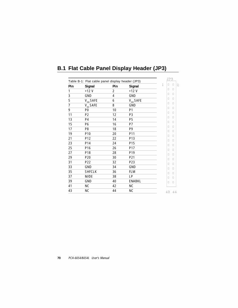
B.1 Flat Cable Panel Display Header (JP3)
Table B-1: Flat cable panel display header (JP3)
Pin Signal Pin Signal1 +12 V 2 +12 V3 GND 4 GND5 VDD SAFE 6 VDD SAFE7 VEE SAFE 8 GND9 P0 10 P111 P2 12 P313 P4 14 P515 P6 16 P717 P8 18 P919 P10 20 P1121 P12 22 P1323 P14 24 P1525 P16 26 P1727 P18 28 P1929 P20 30 P2131 P22 32 P2333 GND 34 GND35 SHFCLK 36 FLM37 M/DE 38 LP39 GND 40 ENABKL41 NC 42 NC43 NC 44 NC

Appendix B Pin Assignments - FPM Receiver (PanelLink) 71
B.2 Flat Cable Panel Display Extension Header(JP4)
Table B-2: Flat cable panel display extension header (JP4)
Pin Signal Pin Signal1 VDD SAFE 2 +5 V3 P24 4 P255 P26 6 P277 P28 8 P299 P30 10 P3111 P32 12 P3313 P34 14 P3515 GND 16 GND
B.3 Backlight Power (J3)
Table B-3: Backlight power (J3)
Pin Signal Pin Signal1 +12 V 2 GND3 ENABKL 4 VBR
5 +5 V

72 PCA-6654/6654L User’s Manual
B.4 Extension Power (J6)
Table B-4: Extension power (J6)
Pin Signal Pin Signal1 +12 V 2 GND3 GND 4 +5 V
Table B-5: Flat panel display (J10)
Pin Signal Pin Signal1 +12 V 2 GND3 +12 V 4 GND5 TXC- 6 TXC+7 +3.3 V 8 GND9 TX0- 10 TX0+11 +3.3 V 12 GND13 TX1- 14 TX1+15 +3.3 V 16 GND17 TX2- 18 TX2+19 KB_Data 20 KB_Clock21 Power Down 22 GND23 +5 V 24 GND25 +5 V 26 GND
B.5 Flat Panel Display (J10)
Appendix B Pin Assignments - FPM Receiver (PanelLink) 73
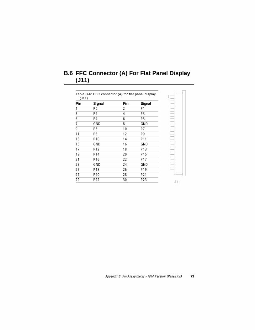
Table B-6: FFC connector (A) for flat panel display(J11)
Pin Signal Pin Signal1 P0 2 P13 P2 4 P35 P4 6 P57 GND 8 GND9 P6 10 P711 P8 12 P913 P10 14 P1115 GND 16 GND17 P12 18 P1319 P14 20 P1521 P16 22 P1723 GND 24 GND25 P18 26 P1927 P20 28 P2129 P22 30 P23
B.6 FFC Connector (A) For Flat Panel Display(J11)

74 PCA-6654/6654L User’s Manual
Table B-7: FFC connector (B) for flat panel display(J12)
Pin Signal Pin Signal1 P24 2 P253 P26 4 P275 P28 6 P297 GND 8 GND9 P30 10 P3111 P32 12 P3313 P34 14 P3515 GND 16 GND17 FLM 18 LP19 GND 20 GND21 SHFCLK 22 M/DE23 GND 24 GND25 VEE SAFE 26 VCON
27 VDD SAFE 28 VDD SAFE29 VDD SAFE 30 VDD SAFE
Table B-8: Keyboard connector (J17)
Pin Signal Pin Signal1 KB_Clock 2 KB_Data3 NC 4 GND5 +5 V
B.7 FFC Connector (B) For Flat Panel Display(J12)
B.8 Keyboard Connector (J17)