pentacle oil field supply inc.pentacleoilfield.com/manuals/kht13625.pdf · pentacle oil field...
TRANSCRIPT
PENTACLE OIL FIELD SUPPLY INC.
16689-113 Avenue Edmonton, Alberta T5M 2X2 Canada
Phone: (780) 902-3485 Fax: (780) 459-6530 Email: [email protected]
MODEL: KHT13625
CASING TONGS
MAINTENANCE AND OPERATION MANUAL

SAFETY CAUTION
1. Operators should read and understand this manual before operation.
2. Operators should wear protective clothing, hard hat and safety boots.
3. Tie the back guy according to the instructions.
4. Make sure to operate at the side of the tong opening.
5. Close the safety door in make-up/break-out operation.
6. Keep hands away from rotating parts.
7. Keep sundries out of the operation range.
8. Cut off the hydraulic source and move the tong off the wellhead during maintenance,
changing dies or other parts.
9. Never use the casing tong under over-pressure or over-torque conditions, otherwise the
tubing will be damaged and so the planetary gear of the tong will be damaged.
10. Don’t dismantle or add parts to the tong.
11. Please adopt the original fitting parts made by TEDA.
Pentacle Oilfield Supply Model KHT13625 _________________________________________________________________________________
780-903-3485 www.pentacleoilfield.com

CONTENTS
1.INTRODUCTION…………………………………………………………………………1
2.SPECIFICATIONS………………………………………………………………………… 1
3.INSTALLATION………………………………………………………………………2~7
4. CARE MAINTENANCE. ……………………………………………………………7~11
5.PROBLEM DIAGNOSIS……………………………………………………………12
6.STORAGE RECOMMENDATIONS……………………………………………………12
7.FIGURES AND DETAILED PARTS TABLES………………………………… 13~53
Pentacle Oilfield Supply Model KHT13625 _________________________________________________________________________________
780-903-3485 www.pentacleoilfield.com

1. INTRODUCTION
KHT13625 Casing Power Tong is used to make up and break out for casing operation in oil fields. It has
greatly reduced the labor of worker, enhanced connection quality of thread and diminished accidents in
inappropriate casing operation. The power tong has the following features as well:
□ Opening type, convenient and prompt to enter and slide off the working position, with an integral tong
head of great strength and rigidity.
□ Double swing head jaws, convenient to assemble and disassemble.
□ Brake belt assembly, easy to operate and convenient to maintain and replace.
□ Open gear supporting structure, improving the strength and rigidity.
□ Wholly hydraulic mode and mechanical gear shift.
□ High strength steel plate used on the shell, increasing the strength. The jaws are cast with precise
technology, artistic and strong.
□ With hydraulic torque indicator and also installation interface, convenient to realize the computer
management.
□ Use safety door hydraulic safety device,of great safety performance.
□ Large torque range,can meet the requirement of larger torque use.
2. SPECIFICATIONS2.1. Jaws available for casing sizes 4″-13 5/8″
Four kinds of common jaws that we supply: 5 1/2″ 、7″、9 5/8″、13 3/8″; Others: 4″、
4 1/2″、7 5/8″、8 5/8″、10 3/4″、11 3/4″、12 3/4″、13 5/8″jaws can be equipped
according to customer's needs
2.2. Opening size 355.4 mm
2.3. Tong head rotation speed
High gear: 30 rpm
Low gear: 5 rpm
2.4. Rated torque High gear: 8.4 kN.m
Low gear: 42 kN.m
2.5. Rated pressure 16 MPa
2.6. Work flow 150 L/min
2.7. Hydraulic power unit Flow 160 L/min
Pressure 20 MPa
Motor power 37 kW
2.8. Overall dimension(L×W×H) 1508×857×1194 mm
Pentacle Oilfield Supply Model KHT13625 _________________________________________________________________________________
780-903-3485 www.pentacleoilfield.com

2.9. Weight 619 kg (including Spring lifter assembly)
3. OPERATION
To insure reliable operation of the tong, it is essential that it is suspended properly. Hydraulic hoses must be
hooked up correctly, and the following instructions concerning tong start up must be followed:
3.1. Jaw installation (see illustration below):
To install the jaws, remove the two jaw pivot bolts from the cage plate. Plate one jaw at a time between the
upper and lower cage plates with the jaw roller pin facing upward. Align the hole in the jaw with the matching
hole in the cage plates, and insert the jaw pivot bolt.
3.2.Tong rig-up
3.2.1. Hang line
The tong should be suspended by 5/8" diameter wire rope, and from a location in the derrick high enough
to assure easy handling and maneuvering of the tong. One end of the rope should be placed through the pulley.
The other end should be tied off in the derrick to form a dead line through a reaction of about 13kN-18kN to keep
balance of the tong. If it can’t be tied off in the derrick, it is necessary to use a TEDA double spring hanger
assembly. This spring hanger allows the tong to compensate for the downward movement of the casing as the
thread made-up.
Pentacle Oilfield Supply Model KHT13625 _________________________________________________________________________________
780-903-3485 www.pentacleoilfield.com

3.2.2. Hydraulic hoses
When the power unit is not running, or the hydraulic pump is disengaged, the hydraulic hoses may be
installed to the tong. The possibility of error in interchanging the high pressure supply hose and the return hose
has been eliminated by using a 1" high pressure hose and a 1-1/4" return hose. These hose couplings are the
self-seal type, and care should be taken to insure complete engagement to prevent partial closure of the check
valve in the coupling.
3.2.3. Back-up line
The use of a 5/8" or larger wire rope is recommended for the tong back-up line. It should be securely
connected to the load cell at the rear of the tong and tied off to a suitable anchor. To assure accurate operation of
the load cell and torque gauge, the back-up line should be connected at a 90 degree angle with the tong, and in the
same horizontal plane. (square and level) (see illustration below):
Outlet
Inlet
Pentacle Oilfield Supply Model KHT13625 _________________________________________________________________________________
780-903-3485 www.pentacleoilfield.com
3.3 Tong operation
3.3.1 Start up procedure
Note: be sure the doors are closed and securely latched before power unit is started to insure safety for
operation personnel.
Use start up procedures as recommended by the power unit engine operator’s manual. Prior to starting
engine, an inspection should be made to assure proper lube oil level in the engine and hydraulic oil level in the
hydraulic reservoir. Open the by-pass valve on the hydraulic system. Check all pressure and return line hose
connections to make sure they are securely installed.
Note: Failure to have these hose connections tight will stop or restrict oil flow and the following failures
could occur:
a. If the pressure supply hose restricts or stops flow, it will result in high pressure on the power unit
hydraulic system which will activate the hydraulic governor and speed the engine up to maximum
RPM.
b. If the return line flow is stopped or restricted, it will result in high pressure on the power unit hydraulic
system, causing the engine to speed up to maximum RPM and possible failure of the motor seal.
After the hoses are checked, start the engine and allow it to idle until warm. After the power unit
engine has been started and hydraulic oil has circulated for approximately 10 minutes, slowly close the
by-pass valve which will allow oil to circulate through the hoses and to the tong. (circulating pressure
should not exceed 200 PSI.) Place the tong gear shifter in low gear and rotate the tong slowly forward
and then reverse with the throttle valve control lever. Once this has been done and the proper size jaws
have been installed, the tong is then ready to run pipe.
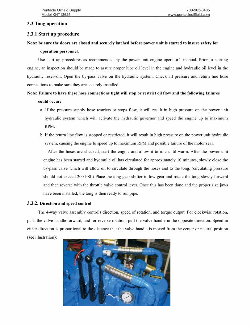
3.3.2. Direction and speed control
The 4-way valve assembly controls direction, speed of rotation, and torque output. For clockwise rotation,
push the valve handle forward, and for reverse rotation, pull the valve handle in the opposite direction. Speed in
either direction is proportional to the distance that the valve handle is moved from the center or neutral position
(see illustration):
Pentacle Oilfield Supply Model KHT13625 _________________________________________________________________________________
780-903-3485 www.pentacleoilfield.com

3.3.3. High and low gear
The primary gear box provides for high and low gear operation. For low gear the shifting handle is simply
moved upward from neutral position, and for high gear, the shifting handle is moved down from neutral position.
(see illustration)
3.3.4. Make up of casing
For proper make-up of a casing joint, the following procedure may be used:
a. Place tong around casing.
b. Close and latch door completely.
C. Place the backing pin in the hole for make-up.
Backing pin
Break-out
High gear
Neutral
Low gear
Pentacle Oilfield Supply Model KHT13625 _________________________________________________________________________________
780-903-3485 www.pentacleoilfield.com

a. Shift transmission into high gear.
b. Push the throttle valve handle forward slightly until casing threads begin to make-up.
c. When casing threads begin to make-up, push the valve handle to full forward until the tong begins
to stall.
d. Release the throttle.
e. Shift gear box into low gear.
f. Engage throttle and make-up casing to desired torque.
g. Reverse tong to disengage jaws and rotate until the table gear aligns with the door opening.
h. Unlatch the door and remove the tong from pipe.
3.3.5. Break-out of Casing
For proper break-out of a casing joint, the following procedure may be used:
a. Place tong around casing.
b. Close and latch door completely.
c. Place the backing pin in the hole (see illustration below) for break-out
d. Shift the transmission into low gear.
e. Pull the throttle valve into full reverse position.
f. Under most “Break-out” conditions, it is recommended to leave the tong in low gear until the joint
is completely unscrewed.
g. Reverse direction of tong until the table gear aligns with the door opening.
h. Unlatch the door and remove the tong from pipe.
Backing pin
Make-up
Pentacle Oilfield Supply Model KHT13625 _________________________________________________________________________________
780-903-3485 www.pentacleoilfield.com
3.3.6. General comments
a. It is recommended that torque not exceed 8000 ft.lbs. Unless both idler gears are in drive position.
This will enhance the life expectancy and dependability of the tong. When operating the tong at high
gear, it is recommended to frequently check the tightness of the door and make periodic adjustments to
assure a secure door fit.
For safety of rig personnel, make sure the door is securely closed and latched at all times.
b. When make-up integral (shouldered) joints, it is essential to make up the last turn of the threads in
low gear. This reduces the tendency of an instant stop or a sudden increase in torque, which induces
high stresses to the gear train.
c. When pulling a string, do not employ the “snap break” method of breaking out joints. By definition,
the “snap break” method is a procedure used by some operations to break-out connections.
This is accomplished by leaving slack in the “jaw-pipe” engagement, and then quickly pulling the throttle
valve control lever allowing the tong to snap into its loaded or high torque conditions. This method, although
very affective in breaking out joints, highly stresses the gear train and very frequently causes gear breakage.
This method is also dangerous to operating personnel.
3. 4.Extreme cold weather operation procedures
3.4.1. The power unit engine operator’s manual should be consulted for possible cold weather operation
precautions.
3.4.2. A gear and bearing lubricant should be selected which is compatible with expected operating climate.
3.4.3. A hydraulic oil should be selected which is compatible with expected operating climate.
3.4.4. After the power unit has been started, in cold weather climates, the hydraulic oil should be allowed to
circulate up to approximately 20 minutes prior to activating the bypass valve allowing fluid to circulate to the
tong.
3.4.5. When cleaning tong parts in extreme cold climates, allowance for proper drying of moisture is important
prior to lubricating.
4. CARE MAINTENANCE
It is suggested that a regular maintenance program be established, to assure dependable operation of the
TEDA Hydraulic power tong. The following recommendations concerning cleaning, lubrication, and adjustments
will enhance the life expectancy of the tong and assure safety to operating personnel.
4.1. CLEANING
The tong should be thoroughly cleaned with a good petroleum base cleaning agent, after each job, prior to
storage. One month later after usage of the new tong, replace the hydraulic oil to clear the sediment on motor and
valve, later, make the change every six months.
Pentacle Oilfield Supply Model KHT13625 _________________________________________________________________________________
780-903-3485 www.pentacleoilfield.com
4.2. LUBRICATION
A good grade of multipurpose bearing lubricant which is compatible with expected ambient temperatures is
recommended along with the following lubrication procedures, at the completion of each job prior to storage
4.2.1 POWER INPUT SHAFT ASSEMBLY BEARINGS
Unscrew the plug screws on the bearing cover, grease should be applied to these bearings through the
grease fittings in the bearing cap located at the bottom face of the tong.
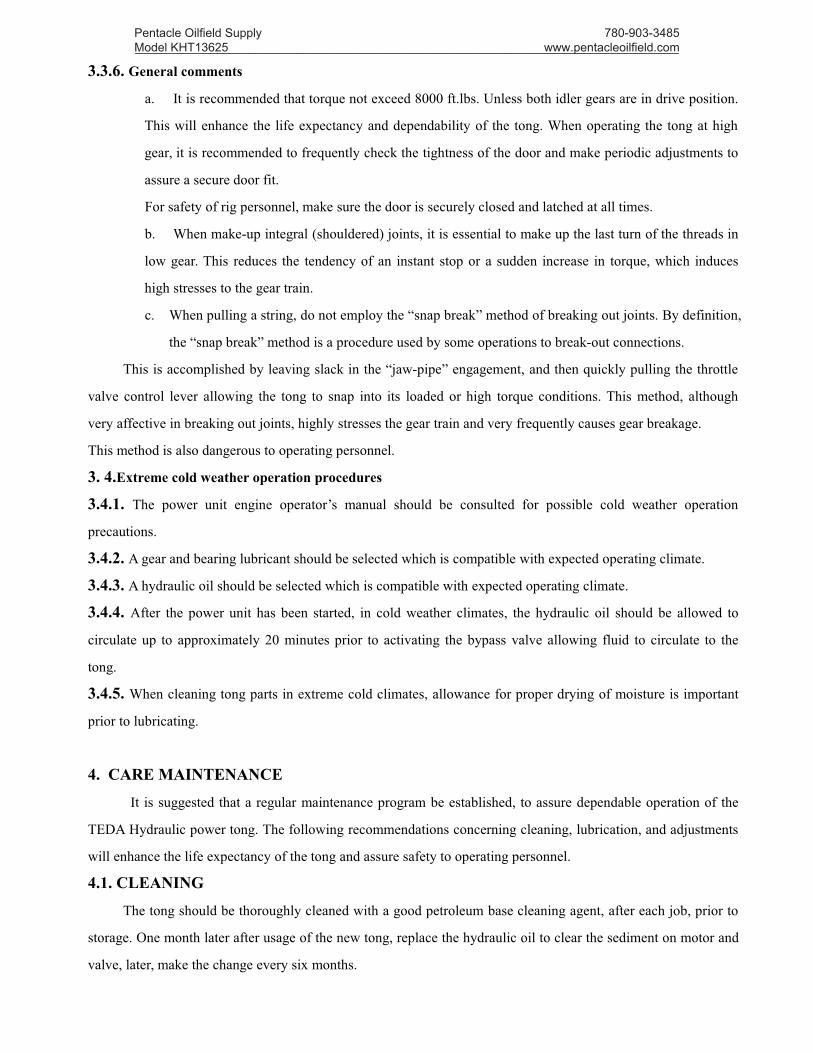
4.2.2 BIG IDLER GEAR ASSEMBLY, SMALL IDLER GEAR ASSEMBLY, PINION ASSEMBLY
Grease should be applied to these bearings through the grease fittings in the end of the shaft located at the
top face of the tong. (see illustration below):
4.2.3 Grease should be applied to these centralizing roller bearings through the grease fittings at the end of the
shafts located at the top and bottom face of the tong. (see illustration above):
4.2.4 Apply grease to the reversing shaft through the shaft seat mouth.
4.3. ADJUSTMENTS
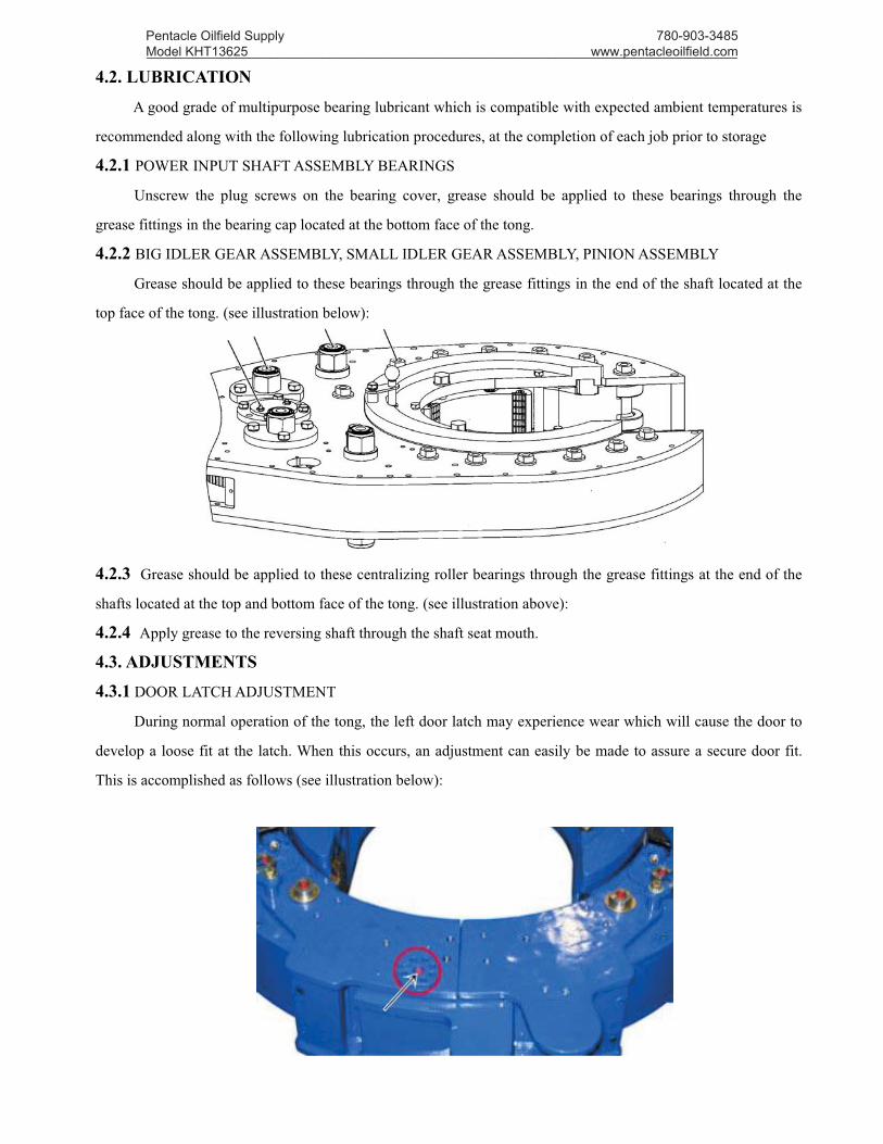
4.3.1 DOOR LATCH ADJUSTMENT
During normal operation of the tong, the left door latch may experience wear which will cause the door to
develop a loose fit at the latch. When this occurs, an adjustment can easily be made to assure a secure door fit.
This is accomplished as follows (see illustration below):
Pentacle Oilfield Supply Model KHT13625 _________________________________________________________________________________
780-903-3485 www.pentacleoilfield.com

Located at the top face of the left door is a latch cam plate which has eight positioning holes located on a
360 degree bolt circle. To make any adjustment in door alignment, the 3/8" hex head bolt located at the top and
bottom latch shaft sleeve should be removed first, then use a wrench to rotate the latch shaft and shaft sleeve,
when desired alignment is achieved, the 3/8" hex head bolt should be tightened.
Note: It is important to keep a secure fit at the doors as this helps maintain proper gear alignment, reduces
possibility of impact torsional stress occurs in the gear case and assure safety to operation
personnel.
4.3.2 BRAKE BAND ADJUSTMENT (see illustration):
As the tong is used, it becomes necessary at times to adjust the brake bands to provide a smoother and more
efficient jaw cam action. If the cage plate turns with the rotary gear, the jaws will not cam properly and therefore,
will not bite on the tubing or casing. By tightening the brake band against the cage plates, enough frictional
resistance occurs to allow jaws to cam properly and grip the casing. To adjust the brake band, simply turn the
adjustment bolt clockwise to tighten and counterclockwise to loosen.
Pentacle Oilfield Supply Model KHT13625 _________________________________________________________________________________
780-903-3485 www.pentacleoilfield.com

4.4. PERIODIC CHECK LIST
4.4.1 DOOR STOP SPRING
To enable the door latch mechanism to snap closed properly, the spring inside the five-way valve must be
of sufficient strength. Door stop spring fatigue will result in a sluggish latch operation. When this occurs, the
latch springs inside the five-way valve should be replaced.
4.4.2 SHIFTING SHAFT
The shifting Yoke is secured to the shifting shaft by one hex jam nut 3/8″×1 3/4″and one nut on the
bottom of the yoke. These nuts should be checked after each job. This can be accomplished by removing the
clutch inspection plate and insuring a snug fit prior to lubrication.
4.4.3. TORQUE GAUGE ASSEMBBLY
Periodic calibration of the torque gauge is recommended to assure accurate torque readings. When having
the torque gauge serviced and calibrated, it is important to note that the arm length on the TEDA 20" tong is 52"
inches.
4.5. OVERHAUL PROCEDURES
Should the need arise to overhaul any portion of the tong, certain disassembly procedures must be
followed. Access to the gear train is possible by removal of the top plate of the tong.
NOTE: All maintenance and overhaul should be accomplished from the top. Therefore, the bottom plate of
the tong should never be removed from the gear case housing.
Pentacle Oilfield Supply Model KHT13625 _________________________________________________________________________________
780-903-3485 www.pentacleoilfield.com
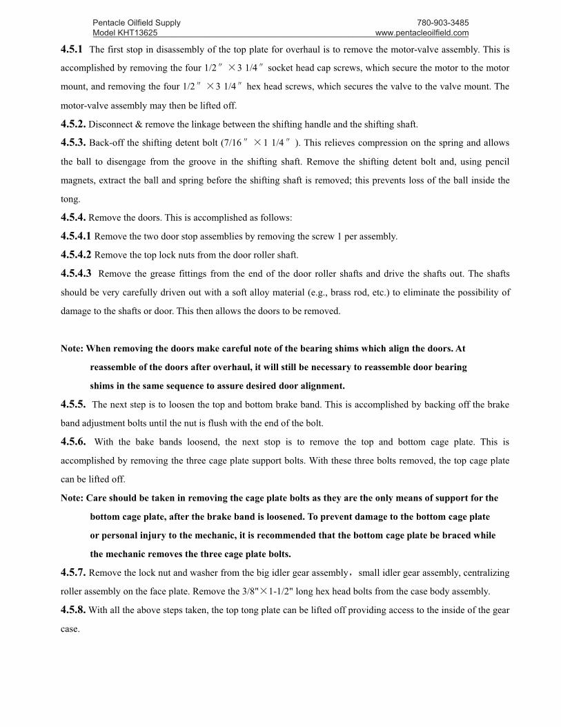
4.5.1 The first stop in disassembly of the top plate for overhaul is to remove the motor-valve assembly. This is
accomplished by removing the four 1/2″×3 1/4″socket head cap screws, which secure the motor to the motor
mount, and removing the four 1/2″×3 1/4″hex head screws, which secures the valve to the valve mount. The
motor-valve assembly may then be lifted off.
4.5.2. Disconnect & remove the linkage between the shifting handle and the shifting shaft.
4.5.3. Back-off the shifting detent bolt (7/16″×1 1/4″). This relieves compression on the spring and allows
the ball to disengage from the groove in the shifting shaft. Remove the shifting detent bolt and, using pencil
magnets, extract the ball and spring before the shifting shaft is removed; this prevents loss of the ball inside the
tong.
4.5.4. Remove the doors. This is accomplished as follows:
4.5.4.1 Remove the two door stop assemblies by removing the screw 1 per assembly.
4.5.4.2 Remove the top lock nuts from the door roller shaft.
4.5.4.3 Remove the grease fittings from the end of the door roller shafts and drive the shafts out. The shafts
should be very carefully driven out with a soft alloy material (e.g., brass rod, etc.) to eliminate the possibility of
damage to the shafts or door. This then allows the doors to be removed.
Note: When removing the doors make careful note of the bearing shims which align the doors. At
reassemble of the doors after overhaul, it will still be necessary to reassemble door bearing
shims in the same sequence to assure desired door alignment.
4.5.5. The next step is to loosen the top and bottom brake band. This is accomplished by backing off the brake
band adjustment bolts until the nut is flush with the end of the bolt.
4.5.6. With the bake bands loosend, the next stop is to remove the top and bottom cage plate. This is
accomplished by removing the three cage plate support bolts. With these three bolts removed, the top cage plate
can be lifted off.
Note: Care should be taken in removing the cage plate bolts as they are the only means of support for the
bottom cage plate, after the brake band is loosened. To prevent damage to the bottom cage plate
or personal injury to the mechanic, it is recommended that the bottom cage plate be braced while
the mechanic removes the three cage plate bolts.
4.5.7. Remove the lock nut and washer from the big idler gear assembly,small idler gear assembly, centralizing
roller assembly on the face plate. Remove the 3/8"×1-1/2" long hex head bolts from the case body assembly.
4.5.8.With all the above steps taken, the top tong plate can be lifted off providing access to the inside of the gear
case.
Pentacle Oilfield Supply Model KHT13625 _________________________________________________________________________________
780-903-3485 www.pentacleoilfield.com

5. PROBLEM DIAGNOSIS
Trouble Causes Remedy
The head doesn’tTurn
l. No pressure from hydraulic station.2. Damage of the hydraulic reversing valve.3. Gear changing system fails.
l. Check the station. Add pressure.2. Replace the valve.3. Repair
Speed is not enoughl. Low pressure or low flow from the powerstation.2. Bad leakage loss from oil motor orhand-reversing valve.
l .Check the station pressure.2. Replace the motor or hand-reversingvalve.
Head slide
l . Disagreement of the sizes of the jaws andcasing.2. Tongs not be leveled.3. Dies worn out.4. Die notch filled with oil dirt.5. Brake band too loose or worn out.6. Jaw roller failure to turn.
l. Change the jaws.2. Level the tongs.3. Change the dies.4. Get rid of it with a wire brush.5. Adjust or change the band.6. Check the roller or oil and repair thepin shaft.
Torque valve less thanrated
l. Low pressure from the hydraulic powerstation or its insufficient oil discharge.2. Function failure of the hydraulic motor or ofthe reversing valve.3.Insufficient oil in the torque cylinder or thesealing ring worn out.4. Torque gauge failure.
l. Deal with it according to theinstruction of hydraulic power station.2. Repair or change it.3. Fill in oil or change the ring.4. Repair or change the torque gauge.
Motor is running butthe tong head keepsstill or moves slowly,or will stop evenloaded light
l. Gear changing device fails2.Much leakage loss from the hydraulic motoror the hand- reversing valve.3. Gear of gearbox damaged or seriously wornout.
1. Repair or change.2.Repair or change the motor and thevalve.3. Check or repair the gearbox .
6. STORAGE RECOMMENDATIONS6.1. When storing the tong, an effort should be made to locate the unit in a clean, dry, ventilated area.
6.2. The tong, while in storage, should be well lubricated.
6.3. Spare moving parts (gears, shafts, etc.), if required to remain in storage for a long period of time, tong
should be coated with a good corrosion inhibitor, and should be stored in a good dry environment.
6.4. All O’ rings, seals, packings, gaskets, etc., should be stored in a good moisture proof, air tight container.
6.5. All bearings (cam followers, roller bearing, etc.) should be well lubricated and stored in a dust free box or
container, protected from moisture.
Pentacle Oilfield Supply Model KHT13625 _________________________________________________________________________________
780-903-3485 www.pentacleoilfield.com
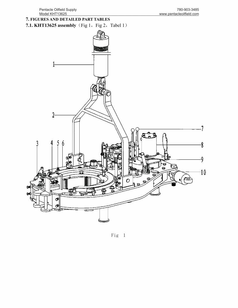
7. FIGURES AND DETAILED PART TABLES7.1. KHT13625 assembly(Fig 1,Fig 2,Tabel 1)
Fig 1
Pentacle Oilfield Supply Model KHT13625 _________________________________________________________________________________
780-903-3485 www.pentacleoilfield.com

Fig 2
Table 1. KHT13625 General assembly
Item P/N Drawing No. Description Qty1 KHT13625-01 TQ340/35Y.1.13(2) Spring lifter assembly 12 KHT13625-02 KHT13625.1.13 Suspension rod assembly 13 KHT13625-03 KHT13625.1.10 Safety door assembly 14 KHT13625-04 KHT13625.1.12 Brake band assembly 25 KHT13625-05 KHT13625.1.1 Tong head assembly 16 KHT13625-06 KHT13625.1.2 Shell 17 KHT13625-07 KHT13625.1.8 Hydraulic valve and line 18 KHT13625-08 KHT13625.1.7 Tong body assembly 19 KHT13625-09 KHT13625.1.11 Shifter assembly 1
10 KHT13625-10 KHT13625.1.14 Torque test assembly 111 KHT13625-11 KHT13625.1.6 Power input shaft assembly 112 KHT13625-12 KHT13625.1.5 Pinion assembly 113 KHT13625-13 KHT13625.1.4 Big idler gear assembly 214 KHT13625-14 KHT13625.1.3 Small idler gear assembly 215 KHT13625-15 KHT13625.1.15 Centralizing assembly 1
Pentacle Oilfield Supply Model KHT13625 _________________________________________________________________________________
780-903-3485 www.pentacleoilfield.com
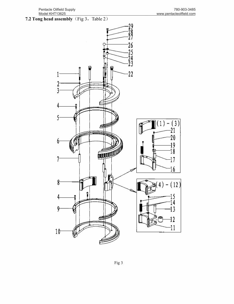
7.2 Tong head assembly(Fig 3,Table 2)
Fig 3
Pentacle Oilfield Supply Model KHT13625 _________________________________________________________________________________
780-903-3485 www.pentacleoilfield.com

Table 2 . Detailed table for tong head assembly
Item P/N Drawing No. Description Qty1 KHT13625-101 KHT13625.1.1-3 Screw rod 1/2″ 32 KHT13625-102 Spring washer 1/2″ 33 KHT13625-103 KHT13625.1.1-1 Upper jaw set bracket 14 KHT13625-104 Hex SHCS 3/8″NC×1 3/4″ 225 KHT13625-105 KHT13625.1.1-10 Upper centralizer plate 16 KHT13625-106 KHT13625.1.1-2 Open gear 17 KHT13625-107 KHT13625.1.1-6 Shaft sleeve(1) 38 KHT13625-108 KHT13625.1.1.1(1)-(12)Jaw set assembly9 KHT13625-109 KHT13625.1.1-11 Lower centralizer plate 1
10 KHT13625-110 KHT13625.1.1-4 Lower jaw set bracket 1
11
KHT13625-111 KHT13625.1.1.1-1(4) Jaw set 4(11 3/4) 2KHT13625-112 KHT13625.1.1.1-1(5) Jaw set 5(10 3/4) 2KHT13625-113 KHT13625.1.1.1-1(6) Jaw set 6(9 5/8) 2KHT13625-114 KHT13625.1.1.1-1(7) Jaw set 7(8 5/8) 2KHT13625-115 KHT13625.1.1.1-1(8) Jaw set 8(7 5/8) 2KHT13625-116 KHT13625.1.1.1-1(9) Jaw set 9(7) 2KHT13625-117 KHT13625.1.1.1-1(10) Jaw set 10(5 1/2) 2KHT13625-118 KHT13625.1.1.1-1(11) Jaw set 11(4 1/2) 2KHT13625-119 KHT13625.1.1.1-1(12) Jaw set 12(4) 2
12 KHT13625-120 KHT13625.1.1.1-2(2) Roller(2) 1813 KHT13625-121 KHT13625.1.1.1-4 Roller shaft 1814 KHT13625-122 KHT9625.1.1.1-2(2) Die2(1/2) 3615 KHT13625-123 Hex flange screw 3/8″UNC×1/2″ 36
16KHT13625-124 KHT13625.1.1.1-1(1) Jaw set 1(13 5/8) 2KHT13625-125 KHT13625.1.1.1-1(2) Jaw set 2(13 3/8) 2KHT13625-126 KHT13625.1.1.1-1(3) Jaw set 3(12 3/4) 2
17 KHT13625-127 KHT13625.1.1.1-2(1) Roller(1) 618 KHT13625-128 KHT13625.1.1.1-1 Press block 619 KHT13625-129 Hex SHCS 3/8″UNC×3/4″ 620 KHT13625-130 KHT13625.1.1.1-3 Die 12
21 KHT13625-131 Hex SHCS 5/16″UNC×1/2″ 1222 KHT13625-132 KHT13625.1.1-5 Jaw set bolt 223 KHT13625-133 KHT13625.1.1-8 Reverse shaft 124 KHT13625-134 KHT13625.1.1-9 Shaft sleeve(2) 125 KHT13625-135 KHT13625.1.1-7 Connection board 126 KHT13625-136 KJD9625.1.1-1 Handle ball 127 KHT13625-137 Flat washer 10 128 KHT13625-138 Spring washer 3/8″ 129 KHT13625-139 Hex bolt 3/8″×1 3/4″ 1
Pentacle Oilfield Supply Model KHT13625 _________________________________________________________________________________
780-903-3485 www.pentacleoilfield.com

7.3Case body assembly(Fig 4,Table 3)
Fig 4
Pentacle Oilfield Supply Model KHT13625 _________________________________________________________________________________
780-903-3485 www.pentacleoilfield.com
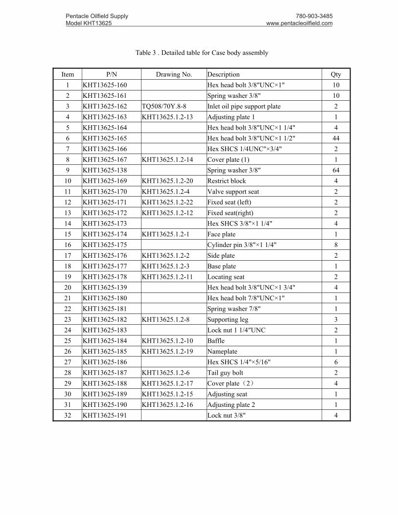
Table 3 . Detailed table for Case body assembly
Item P/N Drawing No. Description Qty1 KHT13625-160 Hex head bolt 3/8"UNC×1" 102 KHT13625-161 Spring washer 3/8" 103 KHT13625-162 TQ508/70Y.8-8 Inlet oil pipe support plate 24 KHT13625-163 KHT13625.1.2-13 Adjusting plate 1 15 KHT13625-164 Hex head bolt 3/8"UNC×1 1/4" 46 KHT13625-165 Hex head bolt 3/8"UNC×1 1/2" 447 KHT13625-166 Hex SHCS 1/4UNC"×3/4" 28 KHT13625-167 KHT13625.1.2-14 Cover plate (1) 19 KHT13625-138 Spring washer 3/8" 64
10 KHT13625-169 KHT13625.1.2-20 Restrict block 411 KHT13625-170 KHT13625.1.2-4 Valve support seat 212 KHT13625-171 KHT13625.1.2-22 Fixed seat (left) 213 KHT13625-172 KHT13625.1.2-12 Fixed seat(right) 214 KHT13625-173 Hex SHCS 3/8"×1 1/4" 415 KHT13625-174 KHT13625.1.2-1 Face plate 116 KHT13625-175 Cylinder pin 3/8"×1 1/4" 817 KHT13625-176 KHT13625.1.2-2 Side plate 218 KHT13625-177 KHT13625.1.2-3 Base plate 119 KHT13625-178 KHT13625.1.2-11 Locating seat 220 KHT13625-139 Hex head bolt 3/8"UNC×1 3/4" 421 KHT13625-180 Hex head bolt 7/8"UNC×1" 122 KHT13625-181 Spring washer 7/8" 123 KHT13625-182 KHT13625.1.2-8 Supporting leg 324 KHT13625-183 Lock nut 1 1/4″UNC 225 KHT13625-184 KHT13625.1.2-10 Baffle 126 KHT13625-185 KHT13625.1.2-19 Nameplate 127 KHT13625-186 Hex SHCS 1/4"×5/16" 628 KHT13625-187 KHT13625.1.2-6 Tail guy bolt 229 KHT13625-188 KHT13625.1.2-17 Cover plate(2) 430 KHT13625-189 KHT13625.1.2-15 Adjusting seat 131 KHT13625-190 KHT13625.1.2-16 Adjusting plate 2 132 KHT13625-191 Lock nut 3/8" 4
Pentacle Oilfield Supply Model KHT13625 _________________________________________________________________________________
780-903-3485 www.pentacleoilfield.com
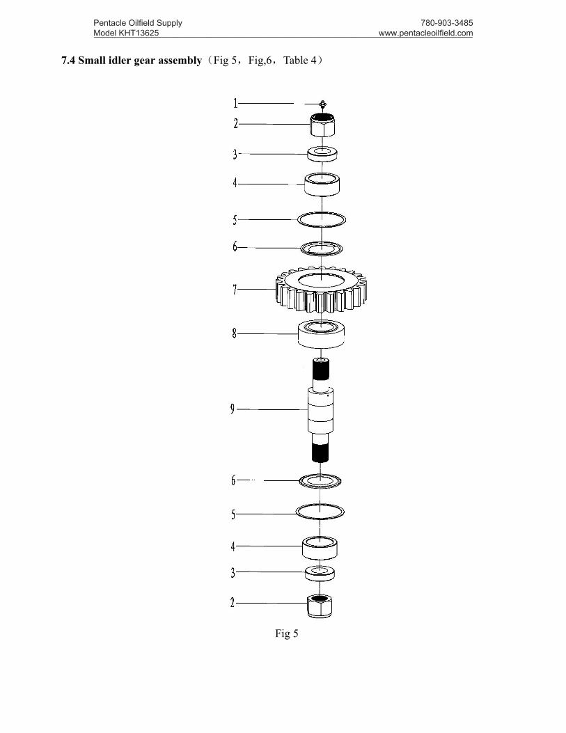
7.4 Small idler gear assembly(Fig 5,Fig,6,Table 4)
Fig 5
Pentacle Oilfield Supply Model KHT13625 _________________________________________________________________________________
780-903-3485 www.pentacleoilfield.com

Fig 6
Table 4 . Detailed table for Small idler gear assembly
Item P/N Drawing No. Description Qty1 KHT13625-210 Oil cup NPT1/8 22 KHT13625-211 TQ508/70Y.3.1 Lock nut 1 1/2-12UNF 23 KHT13625-212 KHT13625.1.3-1 Washer 44 KHT13625-213 KHT13625.1.3-3 Lining ring 45 KHT13625-214 TQ508/70Y.3-5 Retainer ring 46 KHT13625-215 TQ508/70Y.3-4 Water-proof guard(1) 47 KHT13625-216 KHT13625.1.3-4 Small idler gear 28 KHT13625-217 Cylindrical roller bearing MU5212TM 29 KHT13625-218 KHT13625.1.3-2 Small idler gear shaft 2
Pentacle Oilfield Supply Model KHT13625 _________________________________________________________________________________
780-903-3485 www.pentacleoilfield.com

7.5 Big idler gear assembly(Fig 7,Fig 8,Table 5)
Fig 7
Pentacle Oilfield Supply Model KHT13625 _________________________________________________________________________________
780-903-3485 www.pentacleoilfield.com
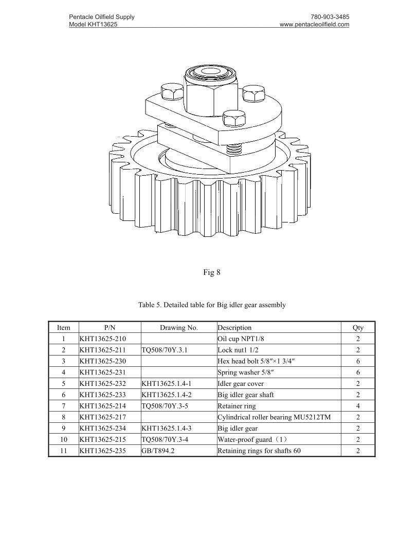
Fig 8
Table 5. Detailed table for Big idler gear assembly
Item P/N Drawing No. Description Qty1 KHT13625-210 Oil cup NPT1/8 22 KHT13625-211 TQ508/70Y.3.1 Lock nut1 1/2 23 KHT13625-230 Hex head bolt 5/8″×1 3/4″ 64 KHT13625-231 Spring washer 5/8″ 65 KHT13625-232 KHT13625.1.4-1 Idler gear cover 26 KHT13625-233 KHT13625.1.4-2 Big idler gear shaft 27 KHT13625-214 TQ508/70Y.3-5 Retainer ring 48 KHT13625-217 Cylindrical roller bearing MU5212TM 29 KHT13625-234 KHT13625.1.4-3 Big idler gear 210 KHT13625-215 TQ508/70Y.3-4 Water-proof guard(1) 211 KHT13625-235 GB/T894.2 Retaining rings for shafts 60 2
Pentacle Oilfield Supply Model KHT13625 _________________________________________________________________________________
780-903-3485 www.pentacleoilfield.com

7.6 Pinion assembly(Fig 9,Fig 10,Table 6)
Fig 9
Pentacle Oilfield Supply Model KHT13625 _________________________________________________________________________________
780-903-3485 www.pentacleoilfield.com
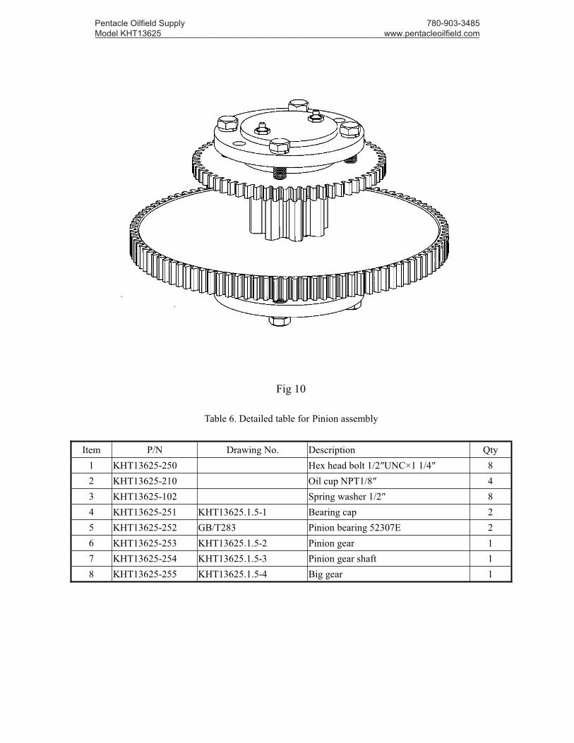
Fig 10
Table 6. Detailed table for Pinion assembly
Item P/N Drawing No. Description Qty1 KHT13625-250 Hex head bolt 1/2″UNC×1 1/4″ 82 KHT13625-210 Oil cup NPT1/8″ 43 KHT13625-102 Spring washer 1/2″ 84 KHT13625-251 KHT13625.1.5-1 Bearing cap 25 KHT13625-252 GB/T283 Pinion bearing 52307E 26 KHT13625-253 KHT13625.1.5-2 Pinion gear 17 KHT13625-254 KHT13625.1.5-3 Pinion gear shaft 18 KHT13625-255 KHT13625.1.5-4 Big gear 1
Pentacle Oilfield Supply Model KHT13625 _________________________________________________________________________________
780-903-3485 www.pentacleoilfield.com

7.7 Power input shaft assembly(Fig 11,Fig 12,Table 7)
Fig 11
Pentacle Oilfield Supply Model KHT13625 _________________________________________________________________________________
780-903-3485 www.pentacleoilfield.com

Fig 12
Table 7. Detailed table for Power input shaft assembly
Item P/N Drawing No. Description Qty1 KHT13625-270 GB/T894.1 Circlip for shaft 34 12 KHT13625-271 KHT13625.1.6-4 Drive gear 13 KHT13625-272 KHT13625.1.6-3 Support ring 14 KHT13625-273 Hex SHCS #10×3/4″ 25 KHT13625-274 GB283-87 Cylindrical roller bearing 207E 16 KHT13625-275 KHT13625.1.6-5 Bearing support 17 KHT13625-276 KHT13625.1.6-6 Support ring(2) 18 KHT13625-277 KHT13625.1.6-7 Duplex hear 19 KHT13625-278 Needle roller bearing B-2412 4
10 KHT13625-279 KHT13625.1.6-8 Inner gear sleeve 111 KHT13625-280 KHT13625.1.6-2 Main shaft 112 KHT13625-281 KHT13625.1.6-9 Clutch small gear 113 KHT13625-282 KHT13625.1.6-10 Support ring(3) 114 KHT13625-283 GB283-87 Cylindrical roller bearing 32206E 115 KHT13625-284 KHT13625.1.6-11 Lower bearing support 116 KHT13625-210 Oil cup NPT1/8 117 KHT13625-286 KHT13625.1.6-12 Plug screw 118 KHT13625-138 Spring washer 3/8″ 419 KHT13625-164 Hex bolt 3/8″UNC×1 1/4″ 420 KHT13625-289 Oil cup NPT1/8×90° 2
Pentacle Oilfield Supply Model KHT13625 _________________________________________________________________________________
780-903-3485 www.pentacleoilfield.com

7.8 Case body assembly(Fig 13,Table 8)
Fig 13
Pentacle Oilfield Supply Model KHT13625 _________________________________________________________________________________
780-903-3485 www.pentacleoilfield.com

Table 8. Detailed table for Case body assembly
Item P/N Drawing No. Description Qty1 KHT13625-300 KHT13625.1.7-2 Torque gauge frame 12 KHT13625-301 Hex bolt 1/2UNC″×3 1/4″ 43 KHT13625-102 Spring washer 1/2″ 44 KHT13625-302 KHT13625.1.7-3 Torque gauge seat 15 KHT13625-303 TQ245-2 Circlip 1
6KHT13625-304A Cycloid hydraulic motor 6K-625(plate type) 1KHT13625-304B Cycloid hydraulic motor 6K-625(tube type) 1
7 KHT13625-305 KHT13625.1.6-13 Washer 48 KHT13625-306 KHT13625.1.6-1B Motor gear 19 KHT13625-307 KHT13625.1.6-15 Lock rings at the end of shaft 1
10 KHT13625-308 GB/T93 Spring washer8 111 KHT13625-309 GB/T70 Hex SHCS M8×25 112 KHT13625-310 KHT13625.1.6-14 Motor connection seat 113 KHT13625-311 Hex SHCS 1/2″UNC×1 3/4″ 414 KHT13625-312 Hex bolt 3/8″UNC×1/2″ 115 KHT13625-313 Oil cupNPT1/8"×45° 116 KHT13625-314 KHT13625.1.7-1 Small case body 117 KHT13625-315 Cylindrical pin Φ5/16″×3/4″ 2
7.9 Hydraulic valve bank (four connection valve)(Fig 14,Table 9)
Pentacle Oilfield Supply Model KHT13625 _________________________________________________________________________________
780-903-3485 www.pentacleoilfield.com
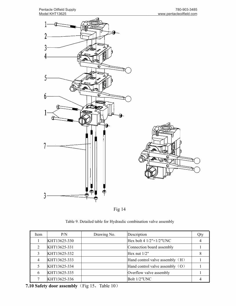
Fig 14
Table 9. Detailed table for Hydraulic combination valve assembly
Item P/N Drawing No. Description Qty1 KHT13625-330 Hex bolt 4 1/2″×1/2″UNC 42 KHT13625-331 Connection board assembly 13 KHT13625-332 Hex nut 1/2″ 84 KHT13625-333 Hand control valve assembly(H) 15 KHT13625-334 Hand control valve assembly(O) 16 KHT13625-335 Overflow valve assembly 17 KHT13625-336 Bolt 1/2″UNC 4
7.10 Safety door assembly(Fig 15,Table 10)
Pentacle Oilfield Supply Model KHT13625 _________________________________________________________________________________
780-903-3485 www.pentacleoilfield.com

Fig 15
Pentacle Oilfield Supply Model KHT13625 _________________________________________________________________________________
780-903-3485 www.pentacleoilfield.com
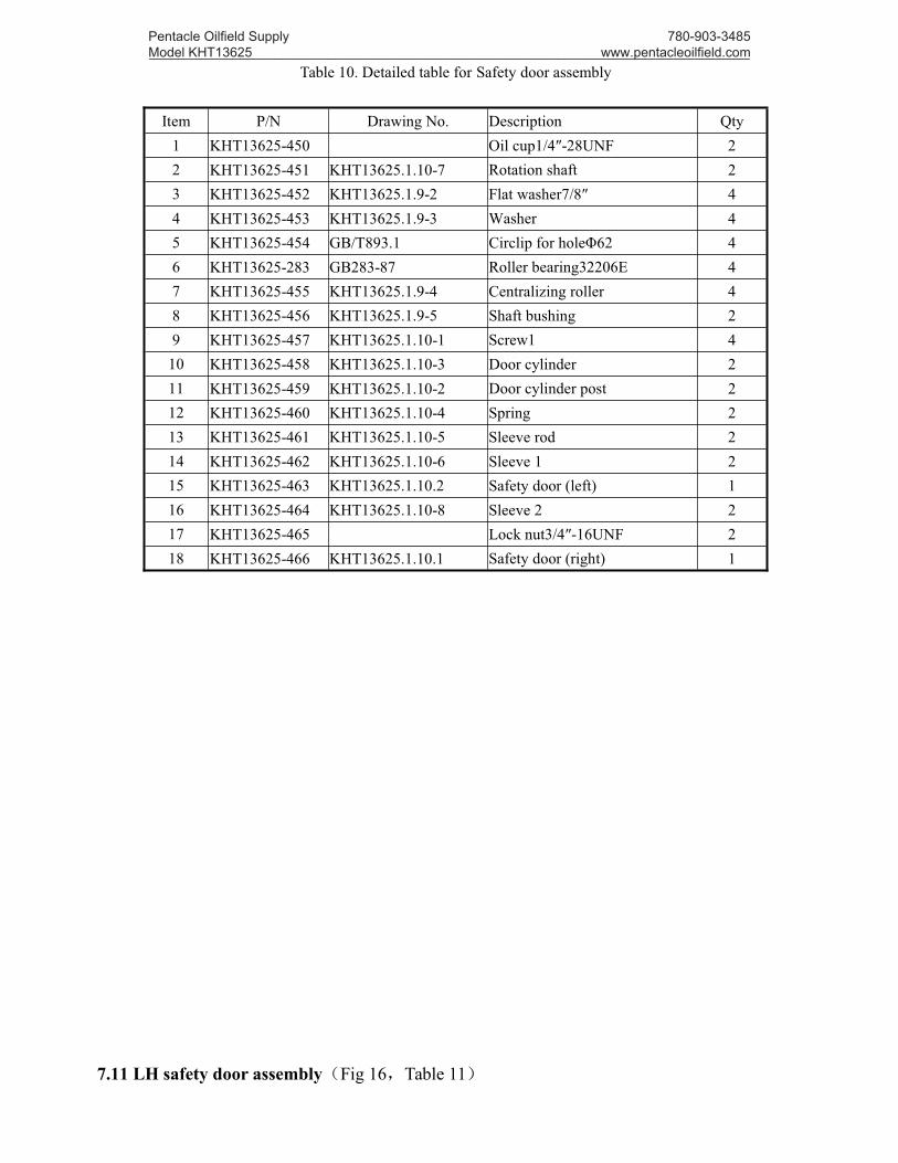
Table 10. Detailed table for Safety door assembly
Item P/N Drawing No. Description Qty1 KHT13625-450 Oil cup1/4″-28UNF 22 KHT13625-451 KHT13625.1.10-7 Rotation shaft 23 KHT13625-452 KHT13625.1.9-2 Flat washer7/8″ 44 KHT13625-453 KHT13625.1.9-3 Washer 45 KHT13625-454 GB/T893.1 Circlip for holeΦ62 46 KHT13625-283 GB283-87 Roller bearing32206E 47 KHT13625-455 KHT13625.1.9-4 Centralizing roller 48 KHT13625-456 KHT13625.1.9-5 Shaft bushing 29 KHT13625-457 KHT13625.1.10-1 Screw1 4
10 KHT13625-458 KHT13625.1.10-3 Door cylinder 211 KHT13625-459 KHT13625.1.10-2 Door cylinder post 212 KHT13625-460 KHT13625.1.10-4 Spring 213 KHT13625-461 KHT13625.1.10-5 Sleeve rod 214 KHT13625-462 KHT13625.1.10-6 Sleeve 1 215 KHT13625-463 KHT13625.1.10.2 Safety door (left) 116 KHT13625-464 KHT13625.1.10-8 Sleeve 2 217 KHT13625-465 Lock nut3/4″-16UNF 218 KHT13625-466 KHT13625.1.10.1 Safety door (right) 1
7.11 LH safety door assembly(Fig 16,Table 11)
Pentacle Oilfield Supply Model KHT13625 _________________________________________________________________________________
780-903-3485 www.pentacleoilfield.com

Fig 16
Table 11. Detailed table for LH safety door assembly
Pentacle Oilfield Supply Model KHT13625 _________________________________________________________________________________
780-903-3485 www.pentacleoilfield.com
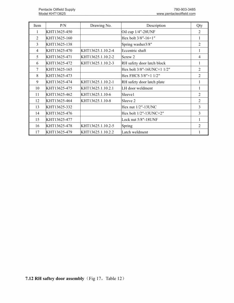
Item P/N Drawing No. Description Qty1 KHT13625-450 Oil cup 1/4″-28UNF 22 KHT13625-160 Hex bolt 3/8″-16×1″ 13 KHT13625-138 Spring washer3/8″ 24 KHT13625-470 KHT13625.1.10.2-4 Eccentric shaft 15 KHT13625-471 KHT13625.1.10.2-2 Screw 2 46 KHT13625-472 KHT13625.1.10.2-3 RH safety door latch block 17 KHT13625-165 Hex bolt 3/8″-16UNC×1 1/2″ 28 KHT13625-473 Hex FHCS 3/8″×1 1/2″ 29 KHT13625-474 KHT13625.1.10.2-1 RH safety door latch plate 1
10 KHT13625-475 KHT13625.1.10.2.1 LH door weldment 111 KHT13625-462 KHT13625.1.10-6 Sleeve1 212 KHT13625-464 KHT13625.1.10-8 Sleeve 2 213 KHT13625-332 Hex nut 1/2″-13UNC 314 KHT13625-476 Hex bolt 1/2″-13UNC×2″ 315 KHT13625-477 Lock nut 5/8″-18UNF 116 KHT13625-478 KHT13625.1.10.2-5 Spring 217 KHT13625-479 KHT13625.1.10.2.2 Latch weldment 1
7.12 RH saftey door assembly(Fig 17,Table 12)
Pentacle Oilfield Supply Model KHT13625 _________________________________________________________________________________
780-903-3485 www.pentacleoilfield.com
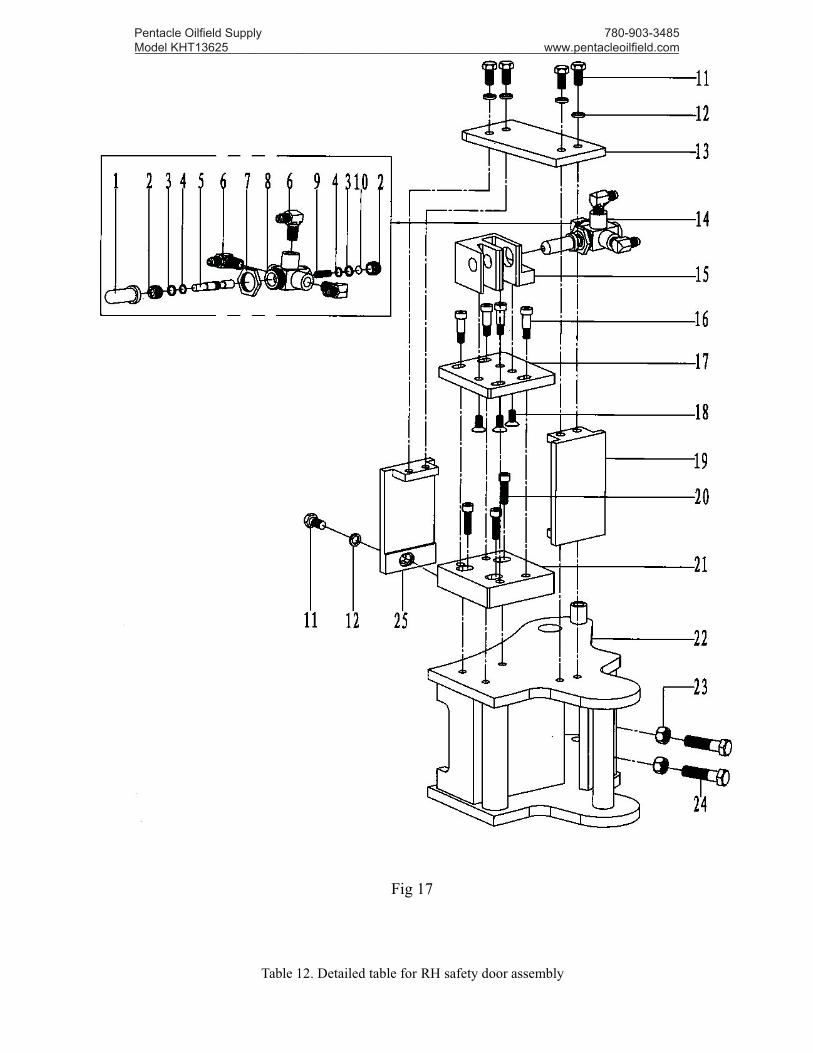
Fig 17
Table 12. Detailed table for RH safety door assembly
Pentacle Oilfield Supply Model KHT13625 _________________________________________________________________________________
780-903-3485 www.pentacleoilfield.com
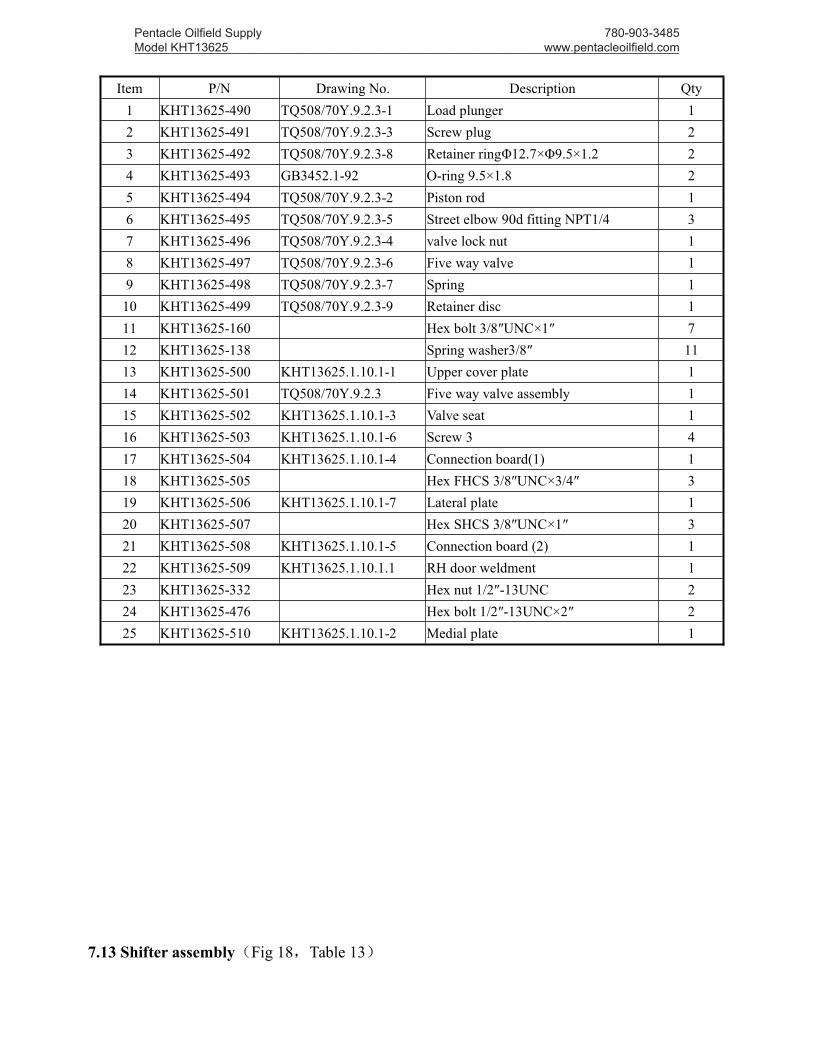
Item P/N Drawing No. Description Qty1 KHT13625-490 TQ508/70Y.9.2.3-1 Load plunger 12 KHT13625-491 TQ508/70Y.9.2.3-3 Screw plug 23 KHT13625-492 TQ508/70Y.9.2.3-8 Retainer ringΦ12.7×Φ9.5×1.2 24 KHT13625-493 GB3452.1-92 O-ring 9.5×1.8 25 KHT13625-494 TQ508/70Y.9.2.3-2 Piston rod 16 KHT13625-495 TQ508/70Y.9.2.3-5 Street elbow 90d fitting NPT1/4 37 KHT13625-496 TQ508/70Y.9.2.3-4 valve lock nut 18 KHT13625-497 TQ508/70Y.9.2.3-6 Five way valve 19 KHT13625-498 TQ508/70Y.9.2.3-7 Spring 1
10 KHT13625-499 TQ508/70Y.9.2.3-9 Retainer disc 111 KHT13625-160 Hex bolt 3/8″UNC×1″ 712 KHT13625-138 Spring washer3/8″ 1113 KHT13625-500 KHT13625.1.10.1-1 Upper cover plate 114 KHT13625-501 TQ508/70Y.9.2.3 Five way valve assembly 115 KHT13625-502 KHT13625.1.10.1-3 Valve seat 116 KHT13625-503 KHT13625.1.10.1-6 Screw 3 417 KHT13625-504 KHT13625.1.10.1-4 Connection board(1) 118 KHT13625-505 Hex FHCS 3/8″UNC×3/4″ 319 KHT13625-506 KHT13625.1.10.1-7 Lateral plate 120 KHT13625-507 Hex SHCS 3/8″UNC×1″ 321 KHT13625-508 KHT13625.1.10.1-5 Connection board (2) 122 KHT13625-509 KHT13625.1.10.1.1 RH door weldment 123 KHT13625-332 Hex nut 1/2″-13UNC 224 KHT13625-476 Hex bolt 1/2″-13UNC×2″ 225 KHT13625-510 KHT13625.1.10.1-2 Medial plate 1
7.13 Shifter assembly(Fig 18,Table 13)
Pentacle Oilfield Supply Model KHT13625 _________________________________________________________________________________
780-903-3485 www.pentacleoilfield.com
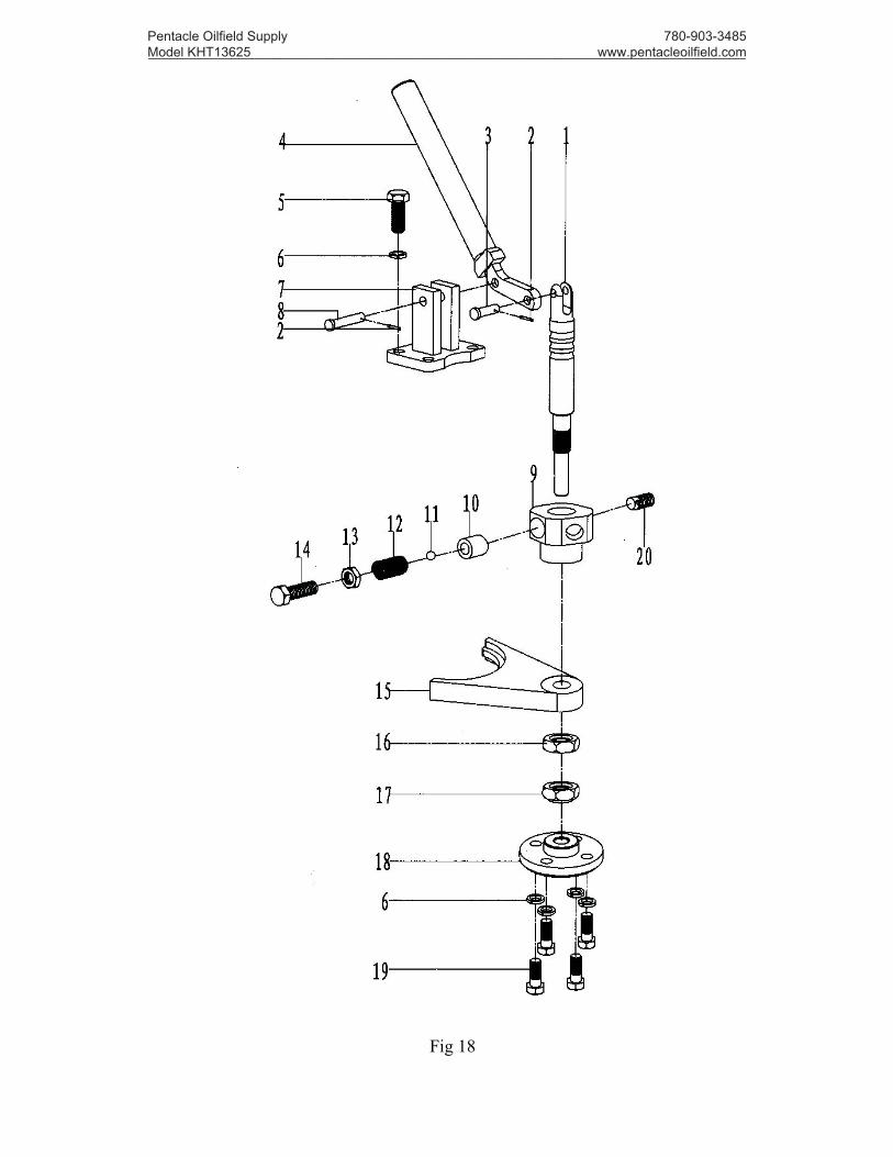
Fig 18
Pentacle Oilfield Supply Model KHT13625 _________________________________________________________________________________
780-903-3485 www.pentacleoilfield.com
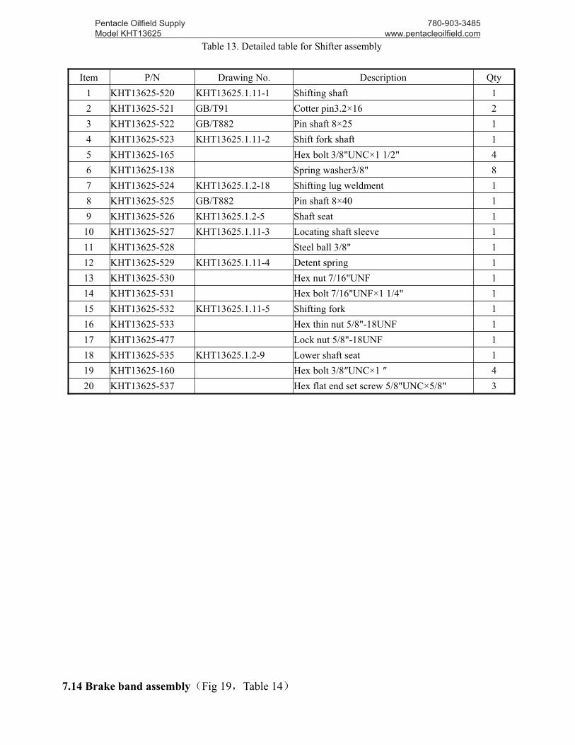
Table 13. Detailed table for Shifter assembly
Item P/N Drawing No. Description Qty1 KHT13625-520 KHT13625.1.11-1 Shifting shaft 12 KHT13625-521 GB/T91 Cotter pin3.2×16 23 KHT13625-522 GB/T882 Pin shaft 8×25 14 KHT13625-523 KHT13625.1.11-2 Shift fork shaft 15 KHT13625-165 Hex bolt 3/8"UNC×1 1/2" 46 KHT13625-138 Spring washer3/8" 87 KHT13625-524 KHT13625.1.2-18 Shifting lug weldment 18 KHT13625-525 GB/T882 Pin shaft 8×40 19 KHT13625-526 KHT13625.1.2-5 Shaft seat 1
10 KHT13625-527 KHT13625.1.11-3 Locating shaft sleeve 111 KHT13625-528 Steel ball 3/8" 112 KHT13625-529 KHT13625.1.11-4 Detent spring 113 KHT13625-530 Hex nut 7/16"UNF 114 KHT13625-531 Hex bolt 7/16"UNF×1 1/4" 115 KHT13625-532 KHT13625.1.11-5 Shifting fork 116 KHT13625-533 Hex thin nut 5/8"-18UNF 117 KHT13625-477 Lock nut 5/8"-18UNF 118 KHT13625-535 KHT13625.1.2-9 Lower shaft seat 119 KHT13625-160 Hex bolt 3/8″UNC×1 ″ 420 KHT13625-537 Hex flat end set screw 5/8"UNC×5/8" 3
7.14 Brake band assembly(Fig 19,Table 14)
Pentacle Oilfield Supply Model KHT13625 _________________________________________________________________________________
780-903-3485 www.pentacleoilfield.com
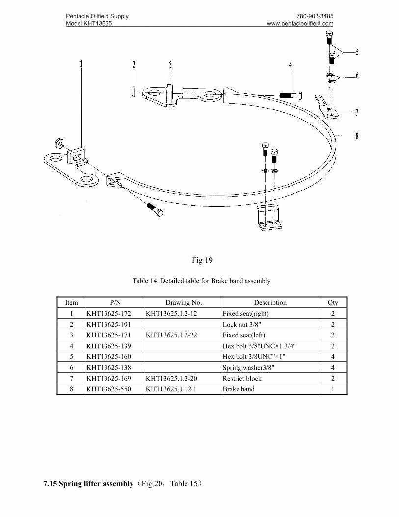
Fig 19
Table 14. Detailed table for Brake band assembly
Item P/N Drawing No. Description Qty1 KHT13625-172 KHT13625.1.2-12 Fixed seat(right) 22 KHT13625-191 Lock nut 3/8" 23 KHT13625-171 KHT13625.1.2-22 Fixed seat(left) 24 KHT13625-139 Hex bolt 3/8"UNC×1 3/4" 25 KHT13625-160 Hex bolt 3/8UNC"×1" 46 KHT13625-138 Spring washer3/8" 47 KHT13625-169 KHT13625.1.2-20 Restrict block 28 KHT13625-550 KHT13625.1.12.1 Brake band 1
7.15 Spring lifter assembly(Fig 20,Table 15)
Pentacle Oilfield Supply Model KHT13625 _________________________________________________________________________________
780-903-3485 www.pentacleoilfield.com
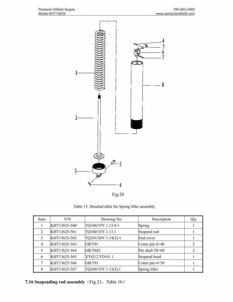
Fig 20
Table 15. Detailed table for Spring lifter assembly
Item P/N Drawing No. Description Qty1 KHT13625-560 TQ340/35Y.1.13-0.1 Spring 12 KHT13625-561 TQ340/35Y.1.13.1 Suspend rod 13 KHT13625-562 TQ245/20Y.1.14(2)-1 End cover 14 KHT13625-563 GB/T91 Cotter pin 4×40 25 KHT13625-564 GB/T882 Pin shaft 20×60 26 KHT13625-565 XYQ12.YD-01.1 Suspend head 17 KHT13625-566 GB/T91 Cotter pin 4×50 18 KHT13625-567 TQ340/35Y.1.13(2).1 Spring lifter 1
7.16 Suspending rod assembly(Fig 21,Table 16)
Pentacle Oilfield Supply Model KHT13625 _________________________________________________________________________________
780-903-3485 www.pentacleoilfield.com

Fig 21
Table 16. Detailed table for Suspending rod assembly
Item P/N Drawing No. Description Qty1 KHT13625-590 Flying ring(5T) 12 KHT13625-591 TQ245.15(2)-1 Screw bar 13 KHT13625-592 GB/T91 Cotter pin 6×45 14 KHT13625-593 TQ245.15(2)-2 Pin shaft 15 KHT13625-594 KHT13625.1.13.1 Suspending rod 16 KHT13625-303 TQ245-2 Circlip 27 KHT13625-595 GB/T882 Pin shaft B25×90 28 KHT13625-596 Hex SHCS 3/8″×2 1/4″ 49 KHT13625-138 Spring washer 3/8″ 4
10 KHT13625-597 KHT13625.1.13-1 Suspend seat 211 KHT13625-332 Hex nut 1/2″ 212 KHT13625-476 Hex bolt 1/2″×2″ 213 KHT13625-599 Hex SHCS 1/2″×1 1/2″ 414 KHT13625-102 Spring washer 1/2″ 4
7.17 Sensor hydraulic cylinder(Fig 22,Table 17)
Pentacle Oilfield Supply Model KHT13625 _________________________________________________________________________________
780-903-3485 www.pentacleoilfield.com

Fig 22
Table 17. Detailed table for Sensor hydraulic cylinder
Item P/N Drawing No. Description Qty1 KHT13625-570 TQ508/70Y.14.1-1 Cylinder end joint 12 KHT13625-571 TQ20.17-2 Adjusting ring 13 KHT13625-572 GB1235-76 O-Ring 70×5.7 14 KHT13625-573 Hex flat end set screw 1/4″×3/8″ 15 KHT13625-574 TQ20.17-4 Piston 16 KHT13625-575 GB3452.1 O-Ring 35.5×2.65 17 KHT13625-576 TQ20.17-3 Cylinder body 18 KHT13625-577 TQ20.17-5 Bending joint 19 KHT13625-578 GB1235-76 O-Ring 44×3.5 1
10 KHT13625-579 FD00641A0 Dustproof ring DK1 38 50 7 10 111 KHT13625-580 TQ20.17-6 Piston Rod 112 KHT13625-581 Hex flat end set screw 3/8″×1/2″ 213 KHT13625-582 PTFE WasherΦ16×Φ6.5×3 114 KHT13625-583 Slotted round head screw 1/4″×3/8″ 115 KHT13625-584 Cross recessed countersunk head screws 316 KHT13625-585 KHT13625.14-1 Torque gauge 117 KHT13625-586 Hose8Ⅱ-700(M20×1.5-NPT 1/4) 1
7.18 Centralizing roller assembly(Fig 23,Fig 24,Table 18)
Pentacle Oilfield Supply Model KHT13625 _________________________________________________________________________________
780-903-3485 www.pentacleoilfield.com

Fig 23
Pentacle Oilfield Supply Model KHT13625 _________________________________________________________________________________
780-903-3485 www.pentacleoilfield.com
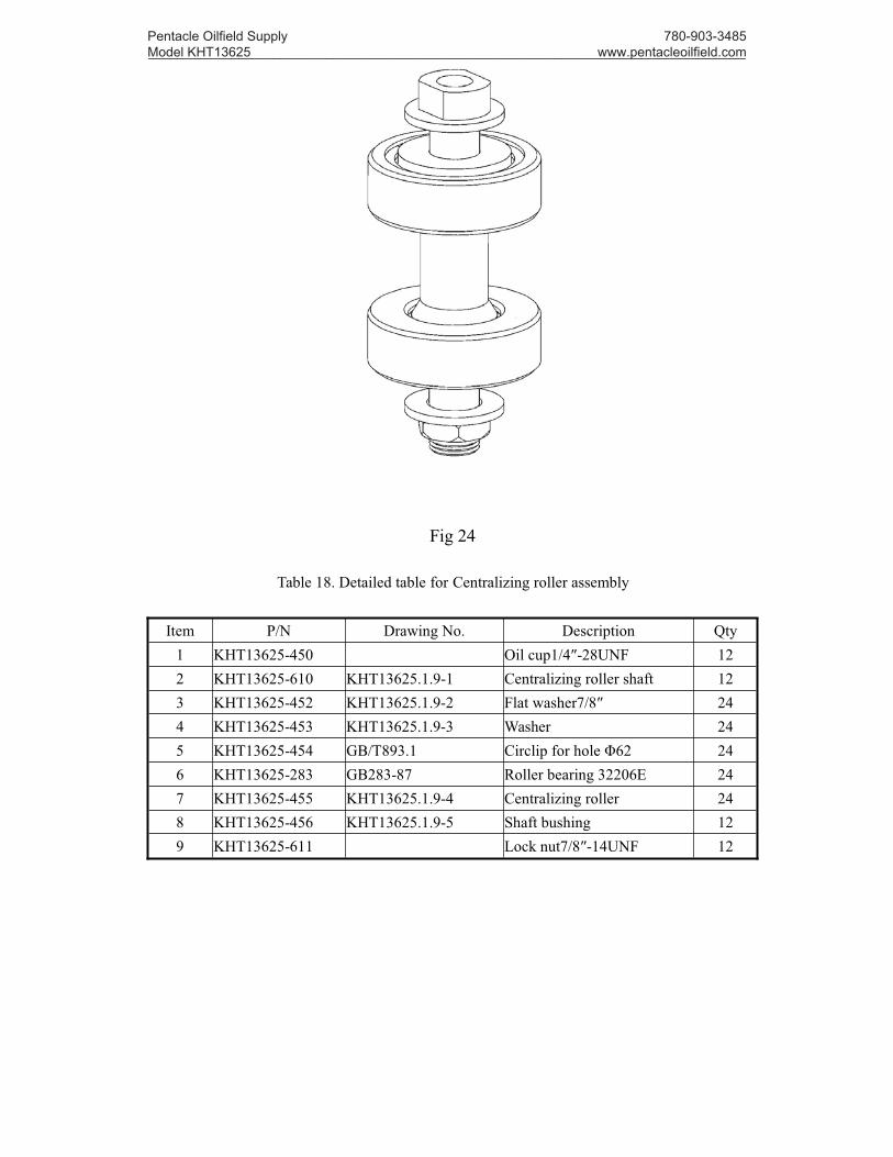
Fig 24
Table 18. Detailed table for Centralizing roller assembly
Item P/N Drawing No. Description Qty1 KHT13625-450 Oil cup1/4″-28UNF 122 KHT13625-610 KHT13625.1.9-1 Centralizing roller shaft 123 KHT13625-452 KHT13625.1.9-2 Flat washer7/8″ 244 KHT13625-453 KHT13625.1.9-3 Washer 245 KHT13625-454 GB/T893.1 Circlip for hole Φ62 246 KHT13625-283 GB283-87 Roller bearing 32206E 247 KHT13625-455 KHT13625.1.9-4 Centralizing roller 248 KHT13625-456 KHT13625.1.9-5 Shaft bushing 129 KHT13625-611 Lock nut7/8″-14UNF 12
Pentacle Oilfield Supply Model KHT13625 _________________________________________________________________________________
780-903-3485 www.pentacleoilfield.com
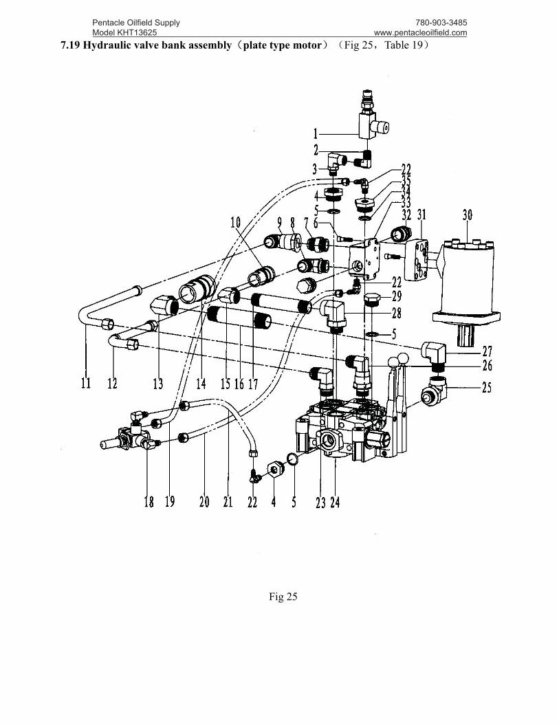
7.19 Hydraulic valve bank assembly(plate type motor)(Fig 25,Table 19)
Fig 25
Pentacle Oilfield Supply Model KHT13625 _________________________________________________________________________________
780-903-3485 www.pentacleoilfield.com
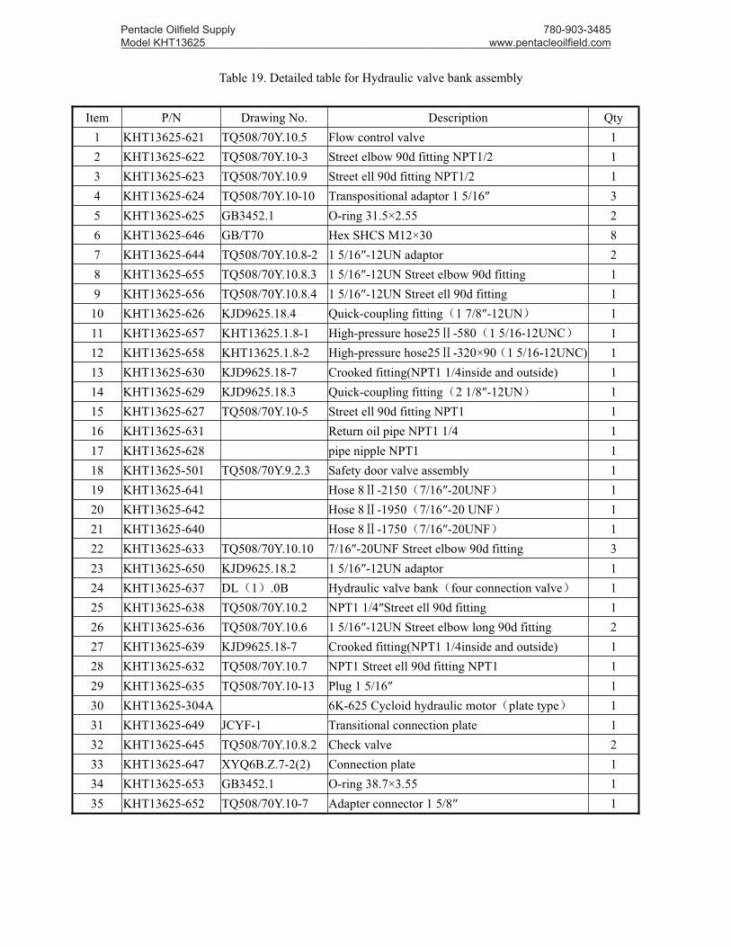
Table 19. Detailed table for Hydraulic valve bank assembly
Item P/N Drawing No. Description Qty1 KHT13625-621 TQ508/70Y.10.5 Flow control valve 12 KHT13625-622 TQ508/70Y.10-3 Street elbow 90d fitting NPT1/2 13 KHT13625-623 TQ508/70Y.10.9 Street ell 90d fitting NPT1/2 14 KHT13625-624 TQ508/70Y.10-10 Transpositional adaptor 1 5/16″ 35 KHT13625-625 GB3452.1 O-ring 31.5×2.55 26 KHT13625-646 GB/T70 Hex SHCS M12×30 87 KHT13625-644 TQ508/70Y.10.8-2 1 5/16″-12UN adaptor 28 KHT13625-655 TQ508/70Y.10.8.3 1 5/16″-12UN Street elbow 90d fitting 19 KHT13625-656 TQ508/70Y.10.8.4 1 5/16″-12UN Street ell 90d fitting 1
10 KHT13625-626 KJD9625.18.4 Quick-coupling fitting(1 7/8″-12UN) 111 KHT13625-657 KHT13625.1.8-1 High-pressure hose25Ⅱ-580(1 5/16-12UNC) 112 KHT13625-658 KHT13625.1.8-2 High-pressure hose25Ⅱ-320×90(1 5/16-12UNC) 113 KHT13625-630 KJD9625.18-7 Crooked fitting(NPT1 1/4inside and outside) 114 KHT13625-629 KJD9625.18.3 Quick-coupling fitting(2 1/8″-12UN) 115 KHT13625-627 TQ508/70Y.10-5 Street ell 90d fitting NPT1 116 KHT13625-631 Return oil pipe NPT1 1/4 117 KHT13625-628 pipe nipple NPT1 118 KHT13625-501 TQ508/70Y.9.2.3 Safety door valve assembly 119 KHT13625-641 Hose 8Ⅱ-2150(7/16″-20UNF) 120 KHT13625-642 Hose 8Ⅱ-1950(7/16″-20 UNF) 121 KHT13625-640 Hose 8Ⅱ-1750(7/16″-20UNF) 122 KHT13625-633 TQ508/70Y.10.10 7/16″-20UNF Street elbow 90d fitting 323 KHT13625-650 KJD9625.18.2 1 5/16″-12UN adaptor 124 KHT13625-637 DL(1).0B Hydraulic valve bank(four connection valve) 125 KHT13625-638 TQ508/70Y.10.2 NPT1 1/4″Street ell 90d fitting 126 KHT13625-636 TQ508/70Y.10.6 1 5/16″-12UN Street elbow long 90d fitting 227 KHT13625-639 KJD9625.18-7 Crooked fitting(NPT1 1/4inside and outside) 128 KHT13625-632 TQ508/70Y.10.7 NPT1 Street ell 90d fitting NPT1 129 KHT13625-635 TQ508/70Y.10-13 Plug 1 5/16″ 130 KHT13625-304A 6K-625 Cycloid hydraulic motor(plate type) 131 KHT13625-649 JCYF-1 Transitional connection plate 132 KHT13625-645 TQ508/70Y.10.8.2 Check valve 233 KHT13625-647 XYQ6B.Z.7-2(2) Connection plate 134 KHT13625-653 GB3452.1 O-ring 38.7×3.55 135 KHT13625-652 TQ508/70Y.10-7 Adapter connector 1 5/8″ 1
Pentacle Oilfield Supply Model KHT13625 _________________________________________________________________________________
780-903-3485 www.pentacleoilfield.com
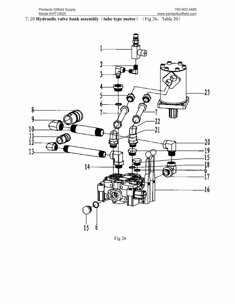
7.20 Hydraulic valve bank assembly(tube type motor)(Fig 26,Table 20)
Fig 26
Pentacle Oilfield Supply Model KHT13625 _________________________________________________________________________________
780-903-3485 www.pentacleoilfield.com
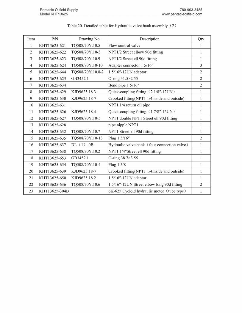
Table 20. Detailed table for Hydraulic valve bank assembly(2)
Item P/N Drawing No. Description Qty1 KHT13625-621 TQ508/70Y.10.5 Flow control valve 12 KHT13625-622 TQ508/70Y.10-3 NPT1/2 Street elbow 90d fitting 13 KHT13625-623 TQ508/70Y.10.9 NPT1/2 Street ell 90d fitting 14 KHT13625-624 TQ508/70Y.10-10 Adapter connector 1 5/16″ 35 KHT13625-644 TQ508/70Y.10.8-2 1 5/16″-12UN adaptor 26 KHT13625-625 GB3452.1 O-ring 31.5×2.55 27 KHT13625-634 Bend pipe 1 5/16″ 28 KHT13625-629 KJD9625.18.3 Quick-coupling fitting(2 1/8″-12UN) 19 KHT13625-630 KJD9625.18-7 Crooked fitting(NPT1 1/4inside and outside) 110 KHT13625-631 NPT1 1/4 return oil pipe 111 KHT13625-626 KJD9625.18.4 Quick-coupling fitting(1 7/8″-12UN) 112 KHT13625-627 TQ508/70Y.10-5 NPT1 double NPT1 Street ell 90d fitting 113 KHT13625-628 pipe nipple NPT1 114 KHT13625-632 TQ508/70Y.10.7 NPT1 Street ell 90d fitting 115 KHT13625-635 TQ508/70Y.10-13 Plug 1 5/16″ 216 KHT13625-637 DL(1).0B Hydraulic valve bank(four connection valve) 117 KHT13625-638 TQ508/70Y.10.2 NPT1 1/4″Street ell 90d fitting 118 KHT13625-653 GB3452.1 O-ring 38.7×3.55 119 KHT13625-654 TQ508/70Y.10-4 Plug 1 5/8 120 KHT13625-639 KJD9625.18-7 Crooked fitting(NPT1 1/4inside and outside) 121 KHT13625-650 KJD9625.18.2 1 5/16″-12UN adaptor 122 KHT13625-636 TQ508/70Y.10.6 1 5/16″-12UN Street elbow long 90d fitting 223 KHT13625-304B 6K-625 Cycloid hydraulic motor(tube type) 1
Pentacle Oilfield Supply Model KHT13625 _________________________________________________________________________________
780-903-3485 www.pentacleoilfield.com

7.21 Check valve assembly(Fig 27,Table 21)
Fig 27
Table 21. Detailed table for Check valve assembly
Item P/N Drawing No. Description Qty1 KHT13625-661 TQ508/70Y.10.8.2-1 Valve core seat 12 KHT13625-662 Φ35.2×1.3 retainer ring 13 KHT13625-663 GB3452.1-92 O-ring 35.5×2.65 14 KHT13625-664 Φ32×1.3 retainer ring 15 KHT13625-665 GB3452.1-92 O-ring 31.5×2.65 16 KHT13625-666 steel wire Φ0.6 17 KHT13625-667 TQ508/70Y.10.8.2-2 Valve core piston 18 KHT13625-668 GB3452.1-92 O-ring 20×2.65 19 KHT13625-669 TQ508/70Y.10.8.2-3 Valve core spring 1
10 KHT13625-670 TQ508/70Y.10.8.2-4 Valve core 111 KHT13625-671 TQ508/70Y.10.8.2-5 piston 112 KHT13625-672 Retainer ringΦ27.3×1.3 213 KHT13625-673 GB3452.1-92 O-ring 26.5×2.65 1
Pentacle Oilfield Supply Model KHT13625 _________________________________________________________________________________
780-903-3485 www.pentacleoilfield.com
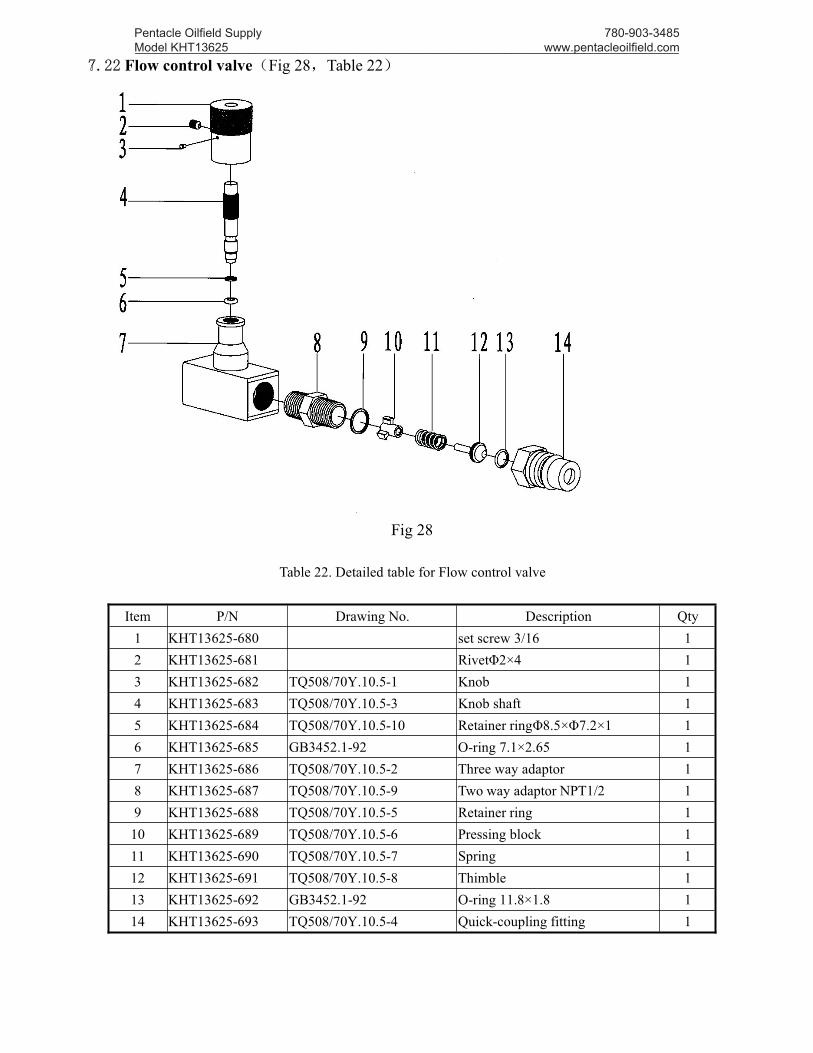
7.22 Flow control valve(Fig 28,Table 22)
Fig 28
Table 22. Detailed table for Flow control valve
Item P/N Drawing No. Description Qty1 KHT13625-680 set screw 3/16 12 KHT13625-681 RivetΦ2×4 13 KHT13625-682 TQ508/70Y.10.5-1 Knob 14 KHT13625-683 TQ508/70Y.10.5-3 Knob shaft 15 KHT13625-684 TQ508/70Y.10.5-10 Retainer ringΦ8.5×Φ7.2×1 16 KHT13625-685 GB3452.1-92 O-ring 7.1×2.65 17 KHT13625-686 TQ508/70Y.10.5-2 Three way adaptor 18 KHT13625-687 TQ508/70Y.10.5-9 Two way adaptor NPT1/2 19 KHT13625-688 TQ508/70Y.10.5-5 Retainer ring 1
10 KHT13625-689 TQ508/70Y.10.5-6 Pressing block 111 KHT13625-690 TQ508/70Y.10.5-7 Spring 112 KHT13625-691 TQ508/70Y.10.5-8 Thimble 113 KHT13625-692 GB3452.1-92 O-ring 11.8×1.8 114 KHT13625-693 TQ508/70Y.10.5-4 Quick-coupling fitting 1
Pentacle Oilfield Supply Model KHT13625 _________________________________________________________________________________
780-903-3485 www.pentacleoilfield.com

7.23 Quick exchange adaptor (2 1/8-12UN) (Fig 29,Table 23)
Fig 29Table 23. Detailed table for Quick exchange adaptor (2 1/8-12UN)
Item P/ N Drawing No. Description Qty1 KHT13625-700 KJD9625.18.3-2 Adaptor body 12 KHT13625-701 KJD9625.18.3-5 Clip 23 KHT13625-702 KJD9625.18.3-4 Washer 14 KHT13625-703 KJD9625.18.3-3 Spring 15 KHT13625-704 KJD9625.18.3.1 Core 16 KHT13625-705 KJD9625.18.3-1 End cover 17 KHT13625-706 KJD9625.18.3.2 Combination chain 1
7.24 Quick exchange adaptor (1 7/8-12UN) (Fig 30,Table 24)
Fig 30Table 24. Detailed table for Quick exchange adaptor (1 7/8-12UN)
Item P/ N Drawing No. Description Qty1 KHT13625-700 KJD9625.18.3-2 Adaptor body 12 KHT13625-701 KJD9625.18.3-5 Clip 23 KHT13625-710 KJD9625.18.3-4 Washer 14 KHT13625-703 KJD9625.18.3-3 Spring 15 KHT13625-711 KJD9625.18.3.1 Core 16 KHT13625-712 KJD9625.18.3-1 End cover 17 KHT13625-706 KJD9625.18.3.2 Combination chain 1
Pentacle Oilfield Supply Model KHT13625 _________________________________________________________________________________
780-903-3485 www.pentacleoilfield.com
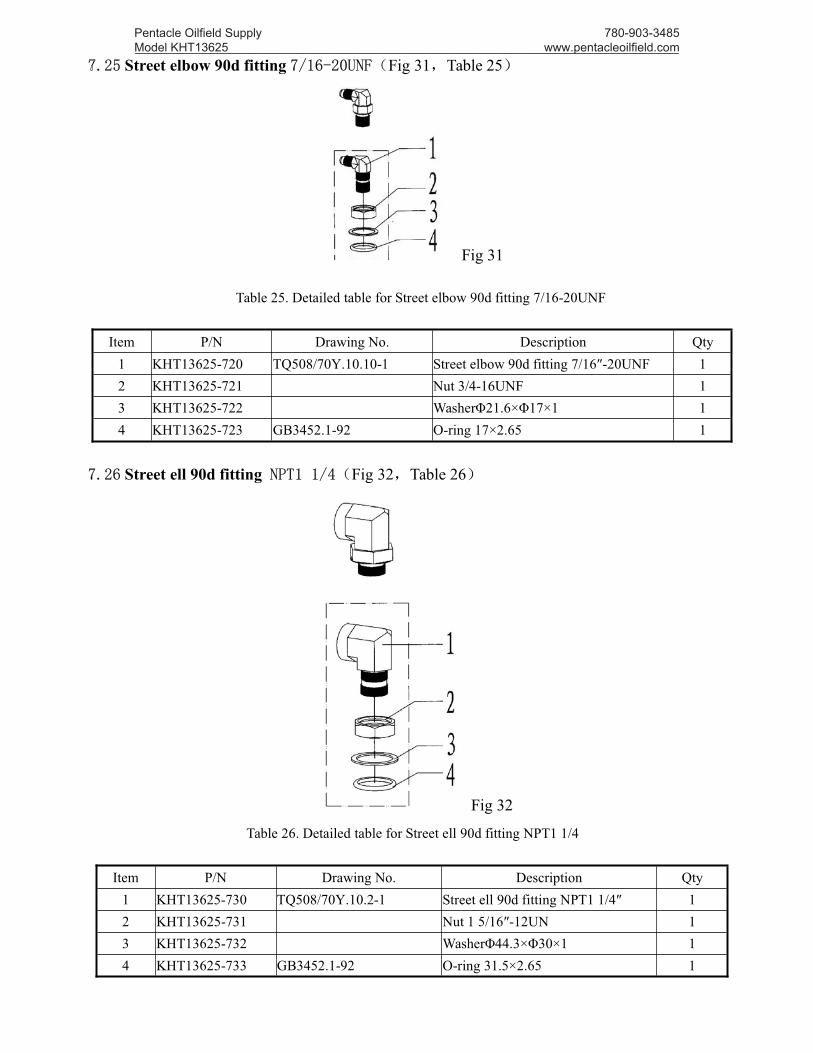
7.25 Street elbow 90d fitting 7/16-20UNF(Fig 31,Table 25)
Fig 31
Table 25. Detailed table for Street elbow 90d fitting 7/16-20UNF
Item P/N Drawing No. Description Qty1 KHT13625-720 TQ508/70Y.10.10-1 Street elbow 90d fitting 7/16″-20UNF 12 KHT13625-721 Nut 3/4-16UNF 13 KHT13625-722 WasherΦ21.6×Φ17×1 14 KHT13625-723 GB3452.1-92 O-ring 17×2.65 1
7.26 Street ell 90d fitting NPT1 1/4(Fig 32,Table 26)
Fig 32
Table 26. Detailed table for Street ell 90d fitting NPT1 1/4
Item P/N Drawing No. Description Qty1 KHT13625-730 TQ508/70Y.10.2-1 Street ell 90d fitting NPT1 1/4″ 12 KHT13625-731 Nut 1 5/16″-12UN 13 KHT13625-732 WasherΦ44.3×Φ30×1 14 KHT13625-733 GB3452.1-92 O-ring 31.5×2.65 1
Pentacle Oilfield Supply Model KHT13625 _________________________________________________________________________________
780-903-3485 www.pentacleoilfield.com

7.27 Street elbow long 90d fitting 1 5/16-12UN(Fig 33,Table 27)
Fig 33
Table 27. Detailed table for Street elbow long 90d fitting 1 5/16-12UN
Item P/N Drawing No. Description Qty1 KHT13625-736 TQ508/70Y.10.6-1 Street elbow long 90d fitting 1 5/16″-12UN 12 KHT13625-731 Nut 1 5/16″-12UN 13 KHT13625-732 Washer Φ44.3×Φ30×1 14 KHT13625-733 GB3452.1-92 O-ring 31.5×2.65 1
7.28 Street ell 90d fitting NPT1(Fig 34,Table 28)
Fig 34
Table 28. Detailed table for Street ell 90d fitting NPT1
Item P/N Drawing No. Description Qty1 KHT13625-740 TQ508/70Y.10.7-1 Street ell 90d fitting NPT1 12 KHT13625-731 Nut 1 5/16″-12UN 13 KHT13625-732 WasherΦ44.3×Φ30×1 14 KHT13625-733 GB3452.1-92 O-ring 31.5×2.65 1
Pentacle Oilfield Supply Model KHT13625 _________________________________________________________________________________
780-903-3485 www.pentacleoilfield.com

7.29 Street ell 90d fitting NPT1/2(Fig 35,Table 29)
Fig 35
Table 29. Detailed table for Street ell 90d fitting NPT1/2
Item P/N Drawing No. Description Qty1 KHT13625-750 TQ508/70Y.10.9-1 Street ell 90d fitting NPT1/2 12 KHT13625-721 Nut 3/4-16UNF 13 KHT13625-722 WasherΦ21.6×Φ17×1 14 KHT13625-723 GB3452.1-92 O-ring 17×2.65 1
Pentacle Oilfield Supply Model KHT13625 _________________________________________________________________________________
780-903-3485 www.pentacleoilfield.com
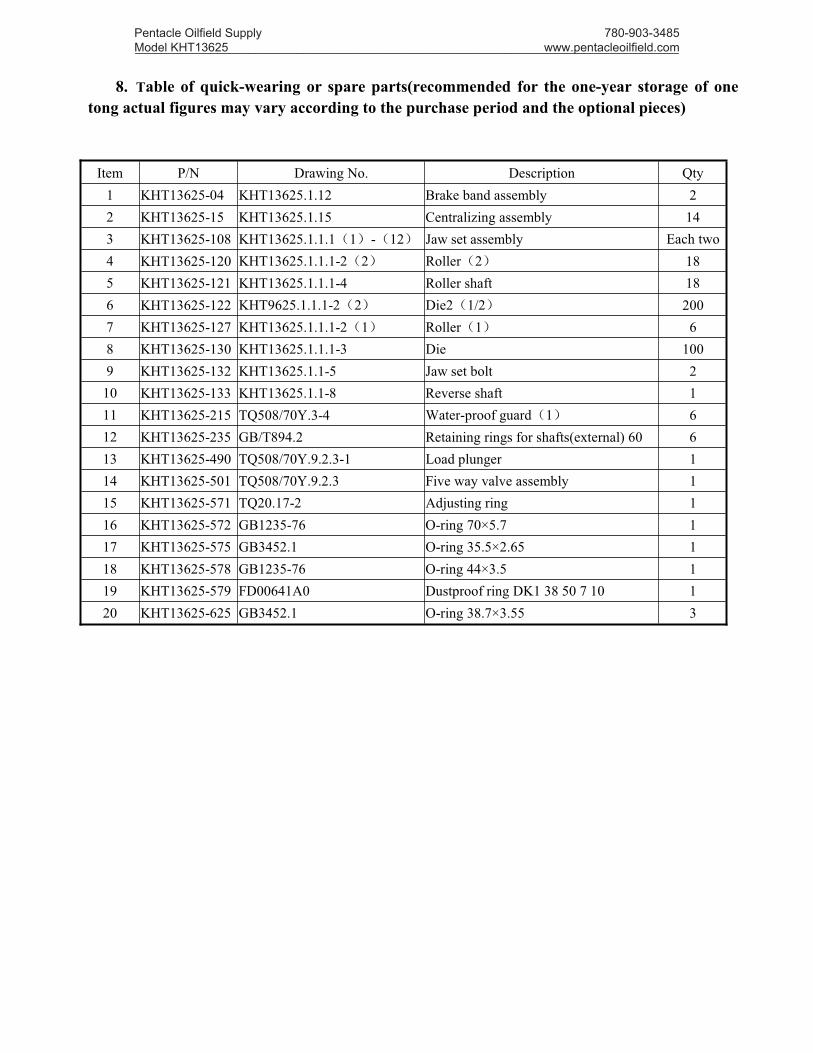
8. Table of quick-wearing or spare parts(recommended for the one-year storage of onetong actual figures may vary according to the purchase period and the optional pieces)
Item P/N Drawing No. Description Qty1 KHT13625-04 KHT13625.1.12 Brake band assembly 22 KHT13625-15 KHT13625.1.15 Centralizing assembly 143 KHT13625-108 KHT13625.1.1.1(1)-(12) Jaw set assembly Each two4 KHT13625-120 KHT13625.1.1.1-2(2) Roller(2) 185 KHT13625-121 KHT13625.1.1.1-4 Roller shaft 186 KHT13625-122 KHT9625.1.1.1-2(2) Die2(1/2) 2007 KHT13625-127 KHT13625.1.1.1-2(1) Roller(1) 68 KHT13625-130 KHT13625.1.1.1-3 Die 1009 KHT13625-132 KHT13625.1.1-5 Jaw set bolt 2
10 KHT13625-133 KHT13625.1.1-8 Reverse shaft 111 KHT13625-215 TQ508/70Y.3-4 Water-proof guard(1) 612 KHT13625-235 GB/T894.2 Retaining rings for shafts(external) 60 613 KHT13625-490 TQ508/70Y.9.2.3-1 Load plunger 114 KHT13625-501 TQ508/70Y.9.2.3 Five way valve assembly 115 KHT13625-571 TQ20.17-2 Adjusting ring 116 KHT13625-572 GB1235-76 O-ring 70×5.7 117 KHT13625-575 GB3452.1 O-ring 35.5×2.65 118 KHT13625-578 GB1235-76 O-ring 44×3.5 119 KHT13625-579 FD00641A0 Dustproof ring DK1 38 50 7 10 120 KHT13625-625 GB3452.1 O-ring 38.7×3.55 3
Pentacle Oilfield Supply Model KHT13625 _________________________________________________________________________________
780-903-3485 www.pentacleoilfield.com