perco-tbc-01. electromechanical box tripod turnstile with
TRANSCRIPT

ASSEMBLY AND OPERATION MANUAL
TBC-01.1
Electromechanical Box TripodTurnstile with Two Built�in Readers and a Card Capture Function

Electromechanical Box Tripod Turnstile
with Two Built-in Readers and a Card Capture Function
TBC-01.1
Assembly & Operation Manual

CONTENTS 1 APPLICATION.............................................................................................................3
2 OPERATION CONDITIONS........................................................................................3
3 TECHNICAL SPECIFICATIONS................................................................................4
4 DELIVERY SET..........................................................................................................5
4.1 Standard delivery set ........................................................................................5 4.2 Optional equipment supplied on request .........................................................5
5 PRODUCT DESCRIPTION .........................................................................................6
5.1 Main features .....................................................................................................6 5.2 Design................................................................................................................6 5.3 Control over the turnstile ................................................................................10 5.4 Input control signals and their parameters at autonomous control...................10 5.5 Control modes..................................................................................................12 5.6 Operation from the RC-panel............................................................................13 5.7 Operation from WRC........................................................................................13 5.8 Operation from an ACS controller ..................................................................14 5.9 Optional external devices connected to the turnstile .........................................14 5.10 Operation contingencies and response ........................................................15 5.11 Card capture reader control..........................................................................15
6 MARKING AND PACKAGING...................................................................................17
7 SAFETY REQUIREMENTS.......................................................................................18
7.1 Installation safety requirements .......................................................................18 7.2 Operation safety requirements.........................................................................18
8 INSTALLATION INSTRUCTIONS.............................................................................19
8.1 Installation details ...........................................................................................19 8.2 Installation tools ...............................................................................................20 8.3 Cable length.....................................................................................................20 8.4 Connection layout of the turnstile and optional equipment...............................20 8.5 Installation procedure.......................................................................................22 8.6 Reorientation of the card capture reader .........................................................23 8.7 An ACS controller installation.........................................................................25
9 OPERATION INSTRUCTIONS ................................................................................27
9.1 Power-up .........................................................................................................27 9.2 Turnstile operating modes in pulse control mode..........................................27 9.3 Operation of the turnstile in potential control mode.......................................29 9.4 Servicing the card container.............................................................................29 9.5 Operation of the turnstile when controlled by an ACS...................................30 9.6 In case of an emergency ................................................................................30 9.7 Possible faults..................................................................................................31
10 MAINTENANCE ........................................................................................................32
11 TRANSPORTATION AND STORAGE ......................................................................33
Appendix 1. Control signal algorithm in pulse control mode....................................34 Appendix 2. Control signal algorithm in potential control mode...............................35

TBC-01.1 Electromechanical Box Tripod Turnstile
Dear Customer!
Thank you for purchasing a box tripod turnstile manufactured by PERCo. Please follow instructions given in this Manual carefully, and this high quality product
will provide many years of trouble-free use.
The Assembly and Operation Manual (hereinafter – the Manual) contains the instructions you will need for safe transportation, storage, installation, operation and maintenance of the TBС-01.1 electromechanical box tripod turnstile with built-in readers and a card capture function (hereinafter – the turnstile).
The product installation must be carried out by qualified installers in strict accordance with the Manual.
Abbreviations adopted in the Manual: ACS – access control system; CLB – control logic board; RC-panel – remote control panel; WRC – wireless remote control.
1 APPLICATION The TBС-01.1 turnstile is designed for pedestrian passage control by proximity cards at entrance points of industrial facilities, banks, administrative buildings, railway terminals, airports, etc.
When operated in an ACS the turnstile is able to capture cards by different criteria (guest passes, passes with time or/and zone violation).
To ensure fast and convenient passage through the turnstile it is recommended to install one TBС-01.1 turnstile per each 500 persons working same shift, or based on the passage pick of 30 persons per minute (Ref. Section 3 for the throughput rate of the turnstile).
2 OPERATION CONDITIONS The turnstile with regard to resistance to environmental exposure complies with GOST15150-69 category NF4 (operation in premises with climate control).
Operation of the turnstile is allowed at an ambient air temperature from +1°C to +40°C and relative air humidity 80% at +25°C.
3
Assembly & Operation Manual
3 TECHNICAL SPECIFICATIONS Operating voltage ............................................................................................. 12±1,2 VDC Consumption current ......................................................................................... max. 1.7 A Power consumption ........................................................................................... max. 20 W Throughput rate in a single passage mode ............................................ 30 persons/min Throughput rate in a free passage mode ............................................... 60 persons/min Passage width......................................................................................................... 580 mm Barrier arm rotation force ................................................................................... max. 3 kgf Number of readers ............................................................................................................. 2 Interface of the reader’s connection with a controller ACS................................. Wiegand1 Card reading distance at the rated operating voltage:
HID cards .............................................................................................. min. 6 cm EM-Marin cards ..................................................................................... min. 8 cm
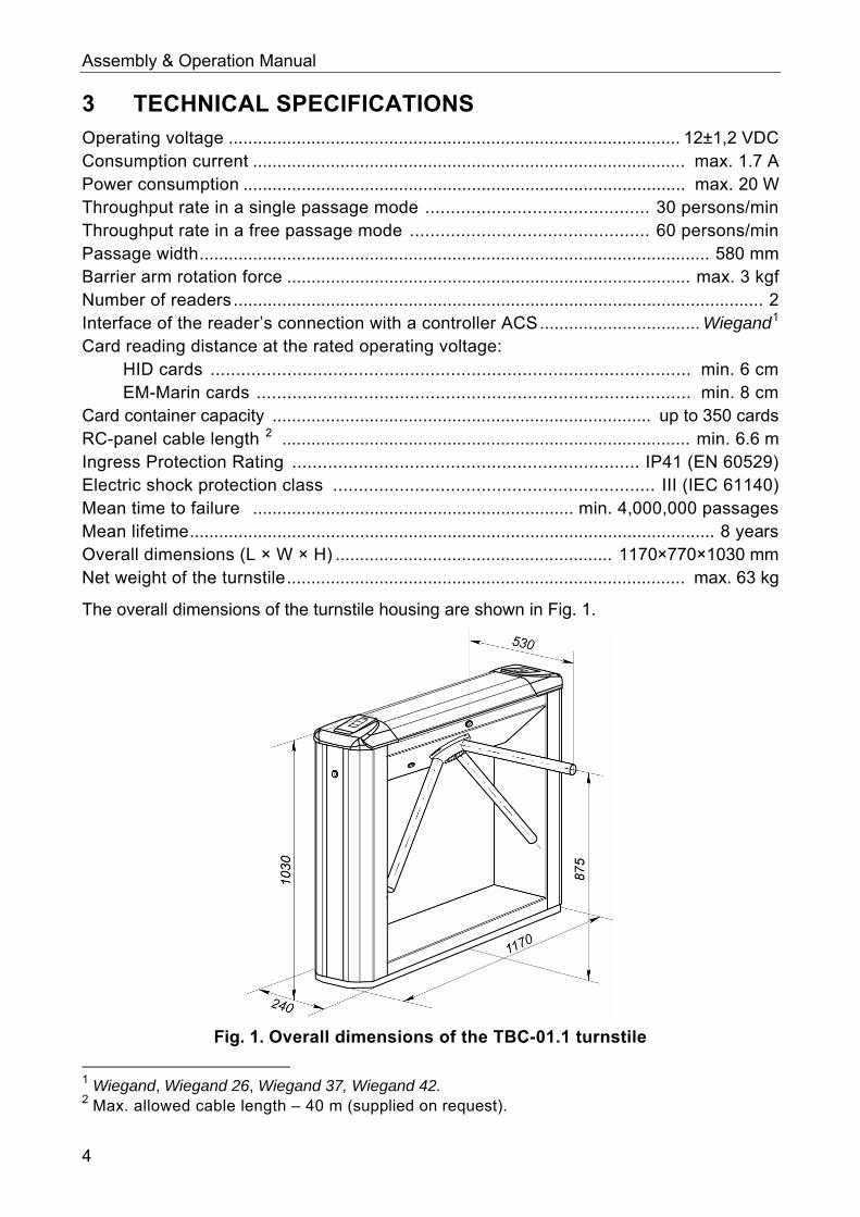
Card container capacity .............................................................................. up to 350 cards RC-panel cable length 2 .................................................................................... min. 6.6 m Ingress Protection Rating .................................................................... IP41 (EN 60529) Electric shock protection class ............................................................... III (IEC 61140) Mean time to failure .................................................................. min. 4,000,000 passages Mean lifetime............................................................................................................ 8 years Overall dimensions (L × W × H) ......................................................... 1170×770×1030 mm Net weight of the turnstile.................................................................................. max. 63 kg
The overall dimensions of the turnstile housing are shown in Fig. 1.
Fig. 1. Overall dimensions of the TBC-01.1 turnstile
1 Wiegand, Wiegand 26, Wiegand 37, Wiegand 42. 2 Max. allowed cable length – 40 m (supplied on request).
4

TBC-01.1 Electromechanical Box Tripod Turnstile
4 DELIVERY SET
4.1 Standard delivery set
Basic equipment:
Turnstile housing ....................................................................................................... 1
Barrier arms................................................................................................................ 3
Note:
The type of the barrier arms are specified in the Certificate TBC-01.1. Key to a housing top cover lock.................................................................................. 2
Mechanical release key.............................................................................................. 2
Key to a card container lock ...................................................................................... 2
Key to a housing side cover lock ............................................................................... 2
RC-panel with cable ................................................................................................... 1
Jumper ....................................................................................................................... 2
Installation tools:
Self-adhesive cable tie mount .................................................................................... 3
Nylon cable tie 100 mm.............................................................................................. 6
Technical documentation:
Certificate ................................................................................................................... 1
Assembly and operation manual ................................................................................ 1
Package:
Box ............................................................................................................................. 1
4.2 Optional equipment supplied on request
SORMAT PFG IR10-15 anchor bolts ........................................................................ 4
Passive infrared sensor of intrusion detector ............................................................. 1
Siren (for alerts on unauthorized entry attempts) ...................................................... 1
Turnstile power supply ................................................................................................1
WRC kit .......................................................................................................................1
Note:
WRC kit consists of a receiver and 2 transmitters (tags) with operation range up to 40 m.
5

Assembly & Operation Manual
5 PRODUCT DESCRIPTION
5.1 Main features
The turnstile can be operated autonomously: from the RC-panel or WRC, as well as from an access control system (ACS) via readers. When operated in an ACS the turnstile is able to capture access cards by a command from the ACS.
Front covers of the turnstile housing feature mnemonic indicators of proximity card readers installed under the front covers.
The front cover at the exit way features a card capture slot with built-in illumination. The card container of the card capture reader is located at the exit way and is locked, and is easy to access for service.
You can set the ACS controller to a special bracket inside the housing of the turnstile, and connect to built-in readers of the turnstile via Wiegand.
The turnstile can be operated in both pulse and potential modes.
A mechanical release lock built into the turnstile housing ensures unlocking of the turnstile with a mechanical release key enabling free rotation of barrier arms in a case of emergency.
At a power supply switching off the turnstile retains the position for each direction set at the moment of power loss: the open passage direction remains open, the closed passage direction remains closed.
A resetting mechanism ensures automatic reset of barrier arms to home position after each passage. Smooth and quite operation of the resetting mechanism is ensured by a damper.
To ensure correct register of passages the resetting mechanism has built-in optic rotation sensors.
Turnstile can be used together with a TB-01.1 model without card capture reader; the TB-01.1 and TBC-01.1 models have matching design and dimensions.
Installed in a line several turnstile housings form a secured passage without installation of extra guide barriers.
The turnstile is supplied with safe operating voltage – maximum 14 V.
The turnstile has low power consumption – maximum 20 W.
5.2 Design 5.2.1 Design of the turnstile is shown in Fig. 2. Numbers of the items hereinafter refer to the item numbers as shown in Fig. 2 unless stated otherwise.
The turnstile consists of a turnstile housing with built-in electronics, two card readers and a card capture reader, three barrier arms and an RC-panel (items 1-3, 5 and 16). The turnstile housing is fixed to floor with 4 anchor bolts through holes in the turnstile housing base (2).
The turnstile housing contains: rotation unit, which includes a resetting mechanism (a pusher, stop springs and a roller), control mechanism with optic sensors and a locking device, as well as a mechanical release lock (7). Rotation unit houses rotation mechanism which includes a damper, a rotation sensor disc and a hub; the point of attachment of the barrier arms to the rotating mechanism is hidden with a cover (6).
6

TBC-01.1 Electromechanical Box Tripod Turnstile
Internal elements of the turnstile housing are accessed through a removable top cover (3); at normal operation of the turnstile the top cover lock (4) is locked.
At the exit way inside the turnstile housing there is a card capture reader mechanism with a card capture reader control board. In same place, at the front side surface of the turnstile housing there is a card container which is locked during normal operation.
In same place on the opposite side there is a side cover instead of a card container installed, which is also locked.
To have an access to the card container unlock the card container lock (12), turn the container taking if off the guide rails.
Fig. 2. TBC-01 overall view
Standard delivery set: 1 – frame; 2 – base; 3 – top cover; items 1-3 form turnstile housing;
4 – top cover lock; 5 – barrier arm, 6 – cover; 7 – mechanical release lock; 8 – indication module; 9,10 – front covers with card readers; 11- blank cover;
12 – card container; 13 – card container lock; 14 – turnstile housing side cover; 15 – turnstile housing side cover lock; 16 – RC-panel; 17 – RC-panel cable
Not included in the standard delivery set: 18 – power cable; 19 – WRC device cable;
20 – ACS connection cable
7

Assembly & Operation Manual
5.2.2 To inform on a current status of the turnstile both front sides of the turnstile housing feature indication modules (8), with card readers built-in under, on the internal side of the cover. The indication module has 3 mnemonic indicators:
– green indicator of authorized passage
– yellow indicator: card presentation is expected
– red indicator of ban on passage
Figure 3. Mnemonic indicators
5.2.3 Inside the turnstile housing there is a bracket with a CLB mounted on it with terminal clamps for connection of external devices. RC-panel, ACS outputs, WRC device (when used), intrusion detector (optional) and emergency unblocking device are connected to the CLB. Connection lines of a power supply unit, signal lines of card readers and card capture reader are connected to the terminal clamps for connection of external devices. External devices are connected in accordance with connection layout (Ref. Fig. 11). The CLB is shown in Fig. 5.
5.2.4 The RC-panel is designed as a small desktop device with a shock-proof ABS plastic case and is intended for setting and indicating operating modes when the turnstile is operated manually. The RC-panel is connected to the CLB with a flexible multicore cable (17) via a XT1.L connector block (Ref. Fig. 5). The RC-panel overall view is shown in Fig. 4.
The front of the RC-panel houses three control buttons with LED indicators above to set passage modes of the turnstile. The “STOP” button in the middle serves for setting the “Always locked” operating mode, the right and left buttons – for unlocking the turnstile in a chosen direction. The RC-panel orientation towards the turnstile (if an operator’s terminal is placed at the backside of the turnstile housing) can be changed by swopping wires of the RC-panel connected to the contacts: Unlock A and Unlock B respectively, as well as Led A and Led B respectively (Ref. Fig. 5 and Fig. 11).
5.2.5 The CLB (Ref. Fig. 5) houses:
X1 (Control) connector to connect the control mechanism (connected to the X1 connector of the control mechanism with the turnstile cable);
XT1.L (In) connector block to connect the RC-panel / WRC / ACS controller inputs as well as an emergency unblocking device;
XT1.H (Out) connector block to connect a siren and outputs, providing the turnstile status data to the ACS controller;
XT2 (Detector) connector block to connect an intrusion detector;
XT3 (+12VDC) connector block to connect the turnstile power supply;
XT4 (Light A) and XT5 (Light B) connector blocks (at delivery indication of top cover card readers is connected to the connector blocks);
J1 connector to select the turnstile control mode;
J2 connector for programming.
8

TBC-01.1 Electromechanical Box Tripod Turnstile
Fig. 4. RC-panel overall view
1, 2, 3 – buttons LEFT, RIGHT, STOP for setting the passage mode; 4, 5 – green indicators «Left», «Right»; 6 – red indicator «Stop»; 7 – RC cable
Fig. 5. The CLB
5.2.6 The turnstile is powered via a power cable (18). As power supply it is recommended to use 12VDC power supply with linear stabilization of voltage and pulsation amplitude at output not exceeding 50 mV. Value of output current should be minimum 1.7 A.
9

Assembly & Operation Manual
5.3 Control over the turnstile 5.3.1 The turnstile can be operated from the following control devices:
RC-panel; WRC; ACS controller.
The above devices can be connected to the turnstile as follows: any device alone; in any combination with each other; all devices simultaneously (in parallel).
Note: At parallel connection of the above devices to the turnstile the superposition of the control signals from them may occur. In that case the turnstile response will conform to response to the obtained combination of input signals (Appendixes1 and 2).
5.3.2 Connection of the devices mentioned in Clause 5.3.1 is made with cables (17, 19, 20) to the corresponding connector blocks XT1.L and XT1.H of the CLB in accordance with the connection layout (Ref. Fig. 11).
5.3.3 The RC-panel is connected to the contacts GND, Unlock A, Stop, Unlock B, Led A, Led Stop and Led B of the XT1.L connector block.
5.3.4 The WRC is connected to the contacts GND, Unlock A, Stop and Unlock B of the XT1.L connector block. Power supply of the WRC is connected to the contact +12V of the XT1.H connector block.
5.3.5 The ACS controller outputs are connected to the contacts GND, Unlock A, Stop and Unlock B of the XT1.L connector block.
5.3.6 The ACS controller inputs are connected to the contacts Common, PASS A, PASS B, Ready and Det Out of the XT1.H connector block.
5.3.7 Pin assignment of the CLB connector blocks are given in Fig. 5 and on a label located on the inner surface of the turnstile top cover.
5.4 Input control signals and their parameters at autonomous control 5.4.1 The CLB microcontroller processes incoming commands (i.e. traces the status of the contacts Unlock A, Stop, Unlock B and Fire Alarm), keeps track of the signals from optic sensors and from the intrusion detector (contact Detector), and based on those signals, generates commands to the control mechanism and to the external devices – indication on the RC-panel (Led A, Led Stop and Led B), the signal of hub turning in the corresponding direction (PASS A and PASS B), the signal of the turnstile ready for a next command (Ready), the alarm output signal (Alarm) – and relays the signal of the current status of the intrusion detector (Det Out).
5.4.2 The turnstile is operated by input of a low-level signal, relatively to the GND contact, to Unlock A, Unlock B and Stop contacts of the XT1.L connector block. As a control element there can be used a normally open relay contact or a circuit with open collector output at that. Emergency unblocking of the turnstile is carried out by removing of a low-level relatively to the GND contact signal from the Fire Alarm contact. As a control element there can be used a normally closed relay contact or a circuit with open collector output at that (Ref. Fig. 6 and 7).
10

TBC-01.1 Electromechanical Box Tripod Turnstile
Fig. 6. Control elements of an external device: a normally open relay contact
Fig. 7. Control elements of an external device: a circuit with open-collector output
Note: For generating of a high-level signal at all input contacts (Unlock A, Stop, Unlock B, Fire Alarm and Detector) 2kOhm resistors connected to the power supply bus “+ 5V” are used.
The control element must provide the following signal characteristics: the relay contact as the control element:
minimum switched current ................................................... no more than 2mA; closed contact resistance
(with resistance of the connection cable) ...................... no more than 300 Ohm; the circuit with open-collector output as the control element:
voltage at the closed contact (low - level signal at the CLB input) ...................................... no more than 0.8V.
5.4.3 The relays “PASS A” (contacts PASS A and Common), “PASS B” (contacts PASS B and Common), “Ready” (contacts Ready and Common), “Detector” (contacts Det Out and Common) and “Alarm” (contacts Alarm 1 and Alarm 2) have normally open contacts. The “Common” contact, common contact for the relays, at that, is not connected to the negative terminal of the turnstile power supply. In the initial (inactive) state, when the power is on, the relay contacts “PASS A”, “PASS B”, “Ready” and “Detector” are closed (voltage is supplied to the relay coil) and the “Alarm” relay contacts are open (voltage is not supplied to the relay coil). Opening/closing of “PASS A”, “PASS B”, “Ready”, “Detector”
11

Assembly & Operation Manual
and “Alarm” relays is indicated by lighting/going out of red indicators located near the corresponding relays (Fig. 5).
The output cascades for PASS A, PASS B, Ready, Det Out and Alarm are the relay contacts with the following signal characteristics (Ref. Fig 8):
maximum commutation voltage................................................................... 42 VDC; maximum switched current............................................................................ 0.25 A; closed contact resistance................................................... no more than 0.15 Ohm.
Fig. 8. Output cascades for PASS A, PASS B, Ready, Det Out and Alarm.
5.5 Control modes 5.5.1 There are two modes of the turnstile control - a pulse control mode and a potential control mode. They determine available operating modes of the turnstile (Table 5 and 6).
5.5.2 The control mode is set by the jumper on a J1 connector (the J1 connector location is shown in Fig 5: the jumper is installed – the pulse control mode, the jumper is not installed – the potential control mode). The jumper is installed at delivery.
5.5.3 At both control modes the turnstile is controlled by input of a control signal. Passage waiting time in the pulse control mode is 5 seconds regardless of duration of the control signal (impulse). In the potential control mode passage waiting time equals duration of the control signal.
5.5.4 The pulse control mode is intended for the turnstile operation from the RC-panel, WRC or an ACS controller, outputs of which support pulse control mode.
Standard control inputs: Unlock A, Unlock B and Stop. Special control input: Fire Alarm.
Refer to Table 5 for the turnstile operating modes at this control mode. The algorithm of control signals at this mode is described in Appendix 1.
To change operating mode of the turnstile the minimum input signal duration should be 100 msec. The passage waiting time is 5 sec. and it does not depend on the input signal duration.
Refer to Clause 5.9.3.1 for the turnstile operation at special Fire Alarm control input.
5.5.5 The potential control mode is intended for the turnstile operation from an ACS controller, outputs of which support potential control mode (for instance lock controller).
Standard control inputs: Unlock A and Unlock B. Special control inputs: Stop and Fire Alarm.
12
TBC-01.1 Electromechanical Box Tripod Turnstile
See Table 6 for the turnstile operating modes at this control mode. The algorithm of control signals at this mode is described in Appendix 2.
To change operating mode of the turnstile the minimum input signal duration should be 100 msec. The passage waiting time is equal to the low-level signal duration (the turnstile remains open in the set direction if a low-level signal already exists at the set direction input at the moment of passage).
At the low-level signal inputting to the Stop input, both directions will lock for the time of the signal duration regardless of the signal strength at the inputs Unlock A and Unlock B. At the removing of a low-level signal from the Stop input, the directions will set to the modes according to the signal strength at the inputs Unlock A and Unlock B.
See Clause 5.9.3.2 for the turnstile operation at the special Fire Alarm control input.
5.6 Operation from the RC-panel 5.6.1 When the buttons on the RC-panel are pressed (the STOP button and the two buttons corresponding to a passage direction), the closing of the relevant contact Stop, Unlock A or Unlock B to the contact GND occurs (i.e. forming of the low-level signal relatively to the contact GND).
5.6.2 Operation logic of the turnstile at the single passage in the A(B) direction at the pulse control mode:
5.6.2.1 When the button, corresponding to the A (B) passage direction, is pressed on the RC-panel, the closing of the contact Unlock A(B) to the contact GND occurs (i.e. forming of the low-level signal on the contact Unlock A(B) relatively to the contact GND). 5.6.2.2 The CLB microcontroller processes an incoming command and generates a command to the control mechanism, which opens the A (B) passage direction (lifts the upper (lower) edge of the key holt). 5.6.2.3 The microcontroller traces a status of the optic sensors, which become active/normal in a certain sequence at barrier arm rotation, and counts the time passed since the moment the RC button corresponding to the permitted passage direction A (B) is pressed. 5.6.2.4 At the barrier arms turning 67° the microcontroller forms signal PASS A (B) (breaking of the contacts PASS A (B) and Common occurs). 5.6.2.5 After the barrier arms turning 67° or after 5 seconds since the moment of pushing the RC button corresponding to the permitted passage direction A (B), the microcontroller generates a command to the control mechanism, which closes the passage direction A (B) (drops the upper (lower) edge of the key holt). 5.6.2.6 When the barrier arms reset to home position (barrier arms turning 112°), the microcontroller removes the signal “PASS A (B)” (contacting of the PASS A (B) and Common takes place).
5.6.3 The “Always free” operating mode particularity: in this mode the command described in Clause 5.6.2.5 is not generated and the set passage direction remains open.
5.7 Operation from WRC 5.7.1 Control over the turnstile with the WRC is similar to that with the RC-panel.
5.7.2 The buttons on the WRC tag act the same way as those on the RC-panel.
5.7.3 WRC operation manual is supplied with that device.
13

Assembly & Operation Manual
5.8 Operation from an ACS controller 5.8.1 In the pulse control mode control over the turnstile from an ACS controller is similar to that one with the RC-panel.
5.8.2 In the potential control mode control over the turnstile from an ACS controller is similar to that one with the RC-panel and lies in forming of a low-level signal on the contacts Unlock A, Stop and Unlock B relatively to the contact GND.
5.8.3 The difference of the operation logic in the potential control mode compared to the one in the pulse control mode (as per Clause 5.6.2 the command described in Clause 5.6.2.5, is generated only at the moment the RC button corresponding to the passage direction A(B) is released. Therefore to arrange single passages in the potential control mode it is recommended to remove the control low-level signal at the beginning of the “PASS” signal of the corresponding direction.
5.8.4 The passage through the turnstile in the A (B) direction gets registered based on the status of the output contacts PASS A(B) and Common.
5.9 Optional external devices connected to the turnstile 5.9.1 The following external devices can be connected to the turnstile:
an intrusion detector and a siren; an emergency unblocking device;
5.9.2 The intrusion detector is connected to the XT2 connector block, and the siren is connected to the XT1.H connector block of the CLB according to the connection layout (Fig. 11 and Fig. 5). The intrusion detector should have normally closed contacts.
Note! Only the manufacturer should carry out installation of an intrusion detector on turnstile housing.
If while the turnstile is in a locked state (in the “Always locked” mode or in the “Both directions locked” mode, Tables 5 and 6) a signal from the intrusion detector comes, the “Alarm” signal is generated, which is disabled either after 5 sec. or after execution of any received command. The signal from the intrusion detector is ignored for the period of authorized unlocking of the turnstile in either or both directions. A signal coming from the intrusion detector within 3 sec. after the “Always locked”/ “Both directions locked” mode is set, is ignored.
A signal on current status of the intrusion detector is constantly transmitted to the Det Out and Common contacts of the CLB XT1.H connector block (Fig. 5).
5.9. The emergency unblocking device is connected to the XT1.L connector block of the CLB in accordance with the connection layout (Fig.11 and Fig. 5). If the Fire Alarm input is not used, it is necessary to install a jumper between the contacts Fire Alarm and GND. This jumper is installed at delivery.
Operation of the turnstile under commands of the emergency unblocking device. 5.9.3.1 In the pulse control mode, when a low-level signal is removed from the Fire Alarm input, both passage directions open for the whole period of the signal absence. Other control commands are ignored at that. When the low-level signal appears at the Fire Alarm input, the turnstile turns to the “Always locked” mode. 5.9.3.2 In the potential control mode, when a low-level signal is removed from the Fire Alarm input, both passage directions open for the whole period of the signal absence. Other control commands are ignored at that. When the low-level signal
14

TBC-01.1 Electromechanical Box Tripod Turnstile
appears at the Fire Alarm input, the passage directions turn to the mode in accordance with the signal levels at the inputs Unlock A, Unlock B and Stop.
5.10 Operation contingencies and response 5.10.1 The turnstile is capable of providing information on the following operation contingencies:
unauthorized access; passage delay for more than 30 sec; one or both optic sensors are out of order.
A special signal “Ready” is generated in each of the above cases.
5.11.2 In case of unauthorized access the “Ready” signal is formed as follows: at 8° arm rotation one of the optic sensors (Fig. 16) responds and the output contacts Ready and Common get broken (the beginning of the signal). When the barrier arms reset to home position, the both optical sensors become normal and the output contacts Ready and Common get closed (the finish of the signal).
5.11.3 In case of delay of an authorized passage for more than 30 sec. the signal “Ready” is formed as follows: if within 30 seconds from the moment of passage commencing, which is determined by the arm rotation at no less than 8° (i.e. activation of one of the optic sensors), the reset of barrier arms to home position does not happen, the output contacts Ready and Common break (the beginning of the signal). When the barrier arms reset to home position, the both optic sensors become normal and the output contacts Ready and Common get closed (finish of the signal).
5.11.4 When one or both of the optic sensors become out of order, the output contacts Ready and Common get broken (the beginning of the signal “Ready”). After fault removal the closed status of the contacts Ready and Common is resumed.
5.11 Card capture reader control 5.12.1 Card capture reader mechanism is controlled from an ACS which sends a signal to the “Capture card” input of the card capture reader control board (contact 17 of the X1.3 connector block, Fig. 5). The card capture reader forms a signal “Card captured” (contact 19 of the X1.3 connector block) and in certain cases a signal “Fault” (contact 20 of the X1.3 connector block, Ref. Fig. 13).
5.12.2 The Capture card input is controlled by an output of a dry contact type or open collector of the ACS controller. The input is a normally open, i.e. when a control signal is sent the ACS controller closes the input to the GND contact (contact 18 of the X1.3 connector block).
The input parameters: Voltage at the opened contact relatively to the “GND” .................................. 5±0.5 V Voltage at the closed contact relatively to the “GND” ............................... max. 0.8 V Current through the closed contact ........................................ not exceeding 1.5 mA
5.12.3 The outputs Card captured and Fault – dry contact. Each of these inputs is one of 2 relay contacts. Other relay contacts are banded and connected to a COM output (contact 21 of the X1.3 connector block). The outputs are normally open, i.e. when a signal is sent the corresponding output closes with the COM contact.
The output parameters: Maximum voltage between a corresponding output and the COM contact ......... 42 V Maximum switched current..............................................................................200 mA
15

Assembly & Operation Manual
Fig. 9. PA-450 control board of the card capture reader
5.12.4 If an access card inserted in a card capture slot in a cover № 1 should be captured an ACS controller sends a signal to the Capture card input.
By this signal an electromagnet opens a shutter that shuts off access to a card container, the card falls down to the card container, i.e. the card is captured. If an optic sensor detects no card in the card capture slot, the electromagnet will not actuate and access to the card container will stay shut off.
When a card falls down to the card container an optic sensor registers that the card has been captured (pass). Only in this case the card capture reader generates a signal “Card captured” for the ACS controller. By this signal the ACS controller removes the “Capture card” signal, after this the card capture reader removes the signal “Card captured”.
As the card capturing process proceeds, the container gets full. Upon its filling the card capture reader slot starts blinking with 2 seconds period, thus informing the staff that the container shall be cleared from cards. If the container is not cleared, then after capturing another 10 cards the operation of the card capture reader is blocked, the "Fault" signal is sent to the ACS controller.
5.11.5 To resume card capturing empty the full card container (Ref. Clause 9.4).
If the card container is empty, but the card capture reader is still blocked a likely reason for this could be failure of the card capture reader units. It is recommended to apply to the PERCO Technical Support Department.
16

TBC-01.1 Electromechanical Box Tripod Turnstile
6 MARKING AND PACKAGING The turnstile has a marking sticker on the internal side of the turnstile top cover and a label – inside, on the rear side of the turnstile housing. To get access to the marking sticker and the label, open the top cover (3).
To do so proceed as follows: Switch off power supply of the turnstile; Insert the key into the top cover lock (4); Turn the key clockwise till it stops (open the lock, the lock cylinder will move out
together with a lock bolt at this); Holding the front edge of the top cover (3) carefully lift it and turning it remove it
from the turnstile housing. Be careful not to damage the CLB located under the cover while removing the top cover;
Place the top cover on a flat steady surface.
Installation of the top cover back into its operation position is carried out in reverse order. After mounting the top cover, lock the top cover lock by pushing lock cylinder into its case till it clicks. Turn on the turnstile power supply.
To protect the turnstile against damage during transportation and storage the turnstile as standard is packed in a transportation box.
Box dimensions (length × width × height) .................................................... 132×110×40 cm Box weight (gross) ................................................................................. not more than 91 kg
17

Assembly & Operation Manual
7 SAFETY REQUIREMENTS
7.1 Installation safety requirements The installation should be carried out only by qualified personnel after careful study of this Manual with observance of general safety rules.
Attention! Only serviceable tools should be used for installation. All works should be performed only after the power supply is switched off and
disconnected from the AC mains. During installation before the turnstile housing is fixed to the floor be careful not
to drop the turnstile housing. Before first power-up of the turnstile make sure installation and all connections
are done properly.
Installation of a power supply unit must be performed with observance of safety requirements mentioned in its certificate.
7.2 Operation safety requirements Observe general electrical safety rules when operating the turnstile.
Do not use: The turnstile under conditions that do not comply with the requirements of
Section 2 of this Manual. The turnstile at supply voltage that does not comply with the requirements of
Section 3 of the Manual.
Power supply unit must be operated with observance of safety requirements mentioned it its certificate.
18

TBC-01.1 Electromechanical Box Tripod Turnstile
8 INSTALLATION INSTRUCTIONS When installing the equipment, observe precautions (see Clause 7.1).
8.1 Installation details It is recommended:
to mount the turnstile on steady and level concrete (grade 400 or higher, strength class B22,5), stone or similar foundations at least 150 mm thick;
to level the foundation so that the anchoring points of the turnstile lie in the same plane (check it with a level);
to apply reinforcing elements (400×400×300 mm) for installation on less steady foundation;
to mark the mounting holes according to Fig.13; to control vertical alignment of the turnstile with a level during installation; to do installation of the turnstile by at least 2 skilled installers.
When arranging a passage areas through the turnstile please take into account that the resetting mechanism operates as follows:
at the barrier arm turning at the angle of more than 60° the reset is effected in the direction of movement;
at the barrier arm turning at the angle less than 60° the reset is effected counter the movement direction (reset to home position).
Note: The angle gradient, at which the barrier arm reset commences, may vary in the range of ± 5°. To ensure accurate passage tracking, when the turnstile is operated from an ACS, it is recommended to arrange the passage area in such a way that the barrier arms should turn in the direction of movement at the angle no less than 70° (Fig. 10).
Fig. 10. Installation recommendations
19

Assembly & Operation Manual
8.2 Installation tools
Hammer drill 1,21,5 kW; hard-alloyed drill bit 16 mm for anchor bolt sleeves; floor chaser for cable raceways; flat slot screwdriver №2; flat slot screwdriver №5 (length 150 mm); cross-head screwdriver №2; horn-type and socket wrenches: S17, S13, S10, S8, S7; level; measuring tape 2 m; slide caliper.
Note: It is allowed to use other testing equipment and measuring tools provided the equipment in use ensures the required parameters and measurement accuracy.
8.3 Cable length The maximum allowed length of the RC-panel / WRC cable is 40 m.
The maximum allowed length of the turnstile power cable depends on the cable cross-section and should not exceed:
for cable with 0.75 mm2 cross – section (AWG 18) .............................. 10 m; for cable with 1.5 mm2 cross – section (AWG 16) ................................ 30 m.
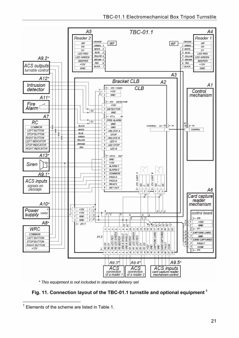
8.4 Connection layout of the turnstile and optional equipment Table 1. Elements of the connection layout
Legend Name Q-ty
A1 Control mechanism 1
A2 Bracket with CLB and connector blocks 1
A3 CLB 1
A4 Cover (with a reader №1) 1
A5 Cover (with a reader №2) 1
A6 Card capture reader mechanism 1
A7 Remote control panel 1
A8* Wireless remote control 1
A9.1*- A9.5* Access control system 1
A10* Turnstile power supply unit 1
A11* Emergency unblocking device (Fire Alarm) 1
A12* Intrusion detector 1
A13* Siren 1
X1.1- X1.2 Connector blocks 1
S1 Wire jumper, installed when the Fire Alarm device (A11) is not connected, installed on default
1
S2 Wire jumper, installed when the intrusion detector (A12) is not connected, installed on default
1
* This equipment is not included in standard delivery set
20
TBC-01.1 Electromechanical Box Tripod Turnstile
Fig. 11. Connection layout of the TBC-01.1 turnstile and optional equipment 1
1 Elements of the scheme are listed in Table 1.
21

Assembly & Operation Manual
8.5 Installation procedure
Attention! The manufacturer shall not be liable for any damage caused as the result of improper installation and declines any claims arising thereof in case if the installation is done not in compliance with the instructions provided in this Manual.
1 Unpack the turnstile and check the completeness as per Section 4 of the product certificate.
2 Make holes for anchor bolt sleeves for the turnstile housing installation (Fig. 13). Prepare a cable raceway for cables when cables are laid concealed under floor. Install and fix the turnstile housing only after all cables inside the turnstile housing and in electric raceways are laid. Cable routing inside the turnstile housing is shown in Fig. 12.
Fig. 12. Cable routing inside the TBC-01.1 turnstile housing:
1 – power cable; 2 – cable from the RC-panel / WRC device; 3 – rotation mechanism connection cable; 4 – cables of card readers №1 and №2;
5 – the CLB; 6 – rotation mechanism; 7 – card capture reader mechanism; 8 – card capture reader cable; 9 – bracket for an ACS controller
№1 – reader cover with a card capture slot; №2 – cover with a reader №1 – cover with reader 1; №2 – cover with reader 2.
22

TBC-01.1 Electromechanical Box Tripod Turnstile
Fig. 13. TBC-01.1 turnstile housing installation layout
3 Insert anchor bolts sleeves into the holes so that they did not stick out above the floor surface.
4 Remove the turnstile housing side cover (14) and card container (12), by unlocking the locks (15 and 13).
5 Set up the housing on anchor bolt sleeves and fix it with the M10 bolts.
6 Install the turnstile power supply unit in its place (See power supply unit certificate for installation procedure of the power supply unit.
7 Remove the turnstile housing top cover (3) by unlocking the lock with a key (4, ref. Section 6).
8 Connect the power cable (18) to a connector block X1.1 (Ref. Fig. 11). Connect the cable (17) of the RC-panel to a connector block XT1.L on the CLB (Fig. 5). Connect cables of other devices, when used, to corresponding connector blocks of the CLB (Ref. Fig 5 and Fig. 11).
9 Check serviceability and accuracy of all the electrical connections. Fix the cables using self-adhesive cable tie mounts and nylon cable ties supplied with a standard delivery set. After all cables are connected and the turnstile housing is fixed to the floor return the top cover (3) to its place (Ref. Section 6) and the turnstile housing side cover (14) and card container (12) in order reverse to their removing.
10 To mount the barrier arms into the run position remove the cover (6) from the hub after unscrewing the screw M4×25. Unscrew the M8×30 bolt on the barrier arm (5). Fit the barrier arm into the mounting hole on the hub and fasten it with the bolt. Put a spring washer under the bolt head. The bolts must be tightened so as to ensure reliable non-play fixation of the barrier arms.
11 Repeat the above-described procedure for fitting up the remaining barrier arms. Put the cover (6) in its operation position and fix it with the screw.
12 Run a test switch on of the turnstile as specified in Clause 9.1.
After the installation and testing are complete the turnstile is ready to operate.
8.6 Reorientation of the card capture reader The card capture reader can be installed either at entrance way or at exit way. When reorientating the card capture reader the front covers with card readers (9, 10) are not swapped over. Card capture reader mechanism is preinstalled at the reader cover № 1 and is connected to the controller as per Clause 5.11.
23

Assembly & Operation Manual
To reorientate the card capture reader mechanism (3, Fig. 14) i.e. to install it to the side of the Reader №1 (Ref. Fig. 12), rather than to the side of the Reader №2 proceed as follows:
1 Take off the top cover (3) in accordance with Clause 6. 2 Remove the card container (12), by opening the lock (13). 3 Remove the turnstile housing side cover (14) from the opposite side by opening the
lock (15). 4 Take off the front covers (9, 10); each front cover is fixed with two M4×16 bolts and
two Ø4.2×19 screws beneath, from the card container side (12) or the turnstile housing side cover (14) side; do not disconnect the card readers cables that are located inside the front covers.
5 Put the front covers on steady and even surface. 6 Remove the blank cover (11) from the front cover (9) and install it to the front cover
(10); the blank cover is fixed with two Ø2.9×9.5 screws. 7 Disconnect the card capture reader cable (8, Fig. 12) from a side of the card
capture reader control board. 8 Dismantle the card capture reader mechanism (3, Fig. 14, – is fixed with 4 bolts
M5×20, 2, Fig. 14) and install it to the opposite side of the turnstile, fixing it in the corresponding place with the same bolts.
9 Reposition the card capture reader cable (8, Fig. 12) to the side of the reader №1. Use self-adhesive cable tie mounts and nylon cable ties from the standard delivery set to fix the cables.
10 Connect the cable of the card capture reader (8, Fig. 12) to the card capture reader control board in accordance with a layout (Fig. 11).
11 Install the front covers (9, 10) back into its operating position and fix in sequence reverse to their removal.
12 Install into operating position the card container (12) on the same side as the card capture reader mechanism, and the turnstile housing side cover – on the opposite side (14).
13 Install the top cover (3) into operation position (Ref. Section 6). 14 After installation works for correct operation of the turnstile and the built-in card
capture reader set an ACS in accordance with the corresponding documentation for the ACS.
Fig. 14. Card capture reader mechanism
1 – card capture reader control board; 2 – fixing bolts of the card capture reader mechanism;
3 – card capture reader mechanism
24

TBC-01.1 Electromechanical Box Tripod Turnstile
8.7 An ACS controller installation The turnstile design has the place designated for mounting of an ACS controller. The ACS controller is mounted on a bracket (9, Fig. 12). Maximum possible size of the mounted board is160×150×35 mm.
The ACS controller is connected to the control board of the turnstile in accordance with Fig. 11. The mechanism of the card capture reader is controlled by the ACS controller according to Section 5.11.
Attention! All connections shall be performed before the voltage is applied to the reader.
Connecting readers to an ACS
The readers are connected to an ACS controller with a shielded cable in accordance with Fig. 11.
The readers’ lines are connected to the connector blocks X1.2 (Ref. Table 2).
For external control over indication from an ACS disconnect from connectors XT4, XT5 of the CLB blue and yellow wires of the readers and connect them to a connector block X1.2 in accordance with color marking (Ref. Table 2).
For external initiation of a sound announcer of a reader its brown wire is connected to a negative terminal of a power supply unit.
Table 2. Pin assignment of the remote terminal block X1.2
№ Pin assignment of the X1.2 The wire from the reader
3 data line D0 green
4 data line D1 white
5 the red indicator light control line blue
6 the green indicator light control line yellow
7 sound signal line brown
8 common cable and shield line shield
Rea
der №
1
9 common cable and shield line shield
10 sound signal line brown
11 the green indicator light control line yellow
12 the red indicator light control line blue
13 data line D1 white
14 data line D0 green
Rea
der №
2
LED indication of a reader is controlled as follows, see Table 3.
Table 3. Control of LED indication reader
Control signals at a connection cable of a reader
Blue wire Yellow wire
LED light in different modes at external control
0 0 red and green
0 HZ red
HZ 0 green
HZ HZ yellow
0 – control line is connected with a negative terminal of a power supply unit; HZ – high resistance at a control line (the line is not connected with a negative terminal of the power supply unit)
25

Assembly & Operation Manual
Change of outcoming data format of the readers
Note! When the cable between a reader and an ACS controller is extended it is recommended to arrange switching over of external control over LED indication and format of outcoming data in the connection place of a regular reader cable with an extension cable.
When the readers are connected to an ACS as per aforementioned scheme format of outcoming data is Wiegand 26 (orange wire – WF is not connected anywhere). Format of outcoming data Wiegand 26 is ensured regardless of a format of used identifiers.
To change a format of outcoming data of Wiegand interface an orange wire is used (WF – Wiegand-Format). To change format of outcoming data of Wiegand interface connect the orange wire (WF) in accordance with the Table 4.
Table 4. Change of outcoming data format of the readers
Connection point (conductor) at an output of a regular connection cable of a reader
Format of outcoming data of a reader determined by performed connections
not connected Wiegand 26
D0 (green) Wiegand 37
+12V (red) Wiegand 42
“ground” (black + shield) Wiegand
26

TBC-01.1 Electromechanical Box Tripod Turnstile
9 OPERATION INSTRUCTIONS When operation the equipment, observe precautions (Clause 7.2).
Warning! Do not use substances for cleaning of the turnstile that may cause mechanical
damage or corrosion of the surfaces;
Do not move through the turnstile passage area any objects with dimensions exceeding the width of the passageway;
Do not jerk and hit any elements of the turnstile so as to prevent their mechanical deformation.
Do not dismantle or adjust mechanisms ensuring operation of the turnstile.
9.1 Power-up 1. Check accuracy of all the connections.
2. Make sure the upper barrier arm is in emergency position (passage area is free).
3. Connect the turnstile power supply unit to the AC outlet with the voltage and frequency rating according to the certificate for the power supply unit.
4. Switch on the turnstile power supply unit. Yellow indicators (card presentation is expected) will light up on the indication modules, on the RC-panel the red indicator above “Always locked” will light up. Manually lift up the folding arm. The arm will be fixed in this position.
9.2 Turnstile operating modes in pulse control mode See Table 5 for the operating modes set from the RC-panel and for the corresponding indication. Please note the following:
- Setting the operating modes for each direction is independent, i.e. setting the operating mode for one direction does not change the operating mode set earlier for the opposite one;
- The “Single passage in the set direction” mode can be changed to the “Always free” mode for the same direction, or to the “Always locked” mode;
- The “Free passage in the set direction” mode can be changed to the “Always locked” mode only.
At the turnstile power supply switching-on the reset sate of the turnstile is “Free passage” (the folding arm is dropped down). It shall be lifted up manually.
In the “Single passage in the set direction” mode the turnstile will lock automatically after a person’s passage in the set direction. The turnstile will also lock automatically, if the passage is not made within 5 sec. In the “Bi-directional single passage” mode after the passage in one direction the countdown of the passage waiting time (5 sec.) for the opposite direction is resumed.
Note:
Pressing the button on the RC-panel corresponds to the low-level signal supply to the contacts (Unlock A, Unlock B and Stop) of the XT1.L connector block relatively to the contact GND.
27
Assembly & Operation Manual
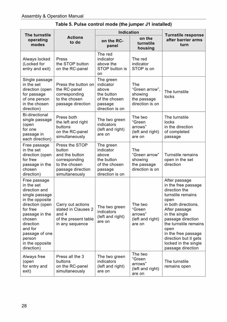
Table 5. Pulse control mode (the jumper J1 installed)
Indication The turnstile
operating modes
Actions to do on the RC-
panel
on the turnstile housing
Turnstile response after barrier arms
turn
Always locked (Locked for entry and exit)
Press the STOP button on the RC-panel
The red indicator above the STOP button is on
The red indicator STOP is on
Single passage in the set direction (open for passage of one person in the chosen direction)
Press the button on the RC-panel corresponding to the chosen passage direction
The green indicator above the button of the chosen passage direction is on
The “Green arrow”, showing the passage direction is on
The turnstile locks
Bi-directional single passage (open for one passage in each direction)
Press both the left and right buttons on the RC-panel simultaneously
The two green indicators (left and right) are on
The two “Green arrows” (left and right) are on
The turnstile locks in the direction of completed passage
Free passage in the set direction (open for free passage in the chosen direction)
Press the STOP button and the button corresponding to the chosen passage direction simultaneously
The green indicator above the button of the chosen passage direction is on
The “Green arrow” showing the passage direction is on
Turnstile remains open in the set direction
Free passage in the set direction and single passage in the opposite direction (open for free passage in the chosen direction and for passage of one person in the opposite direction)
Carry out actions stated in Clauses 2 and 4 of the present table in any sequence
The two green indicators (left and right) are on
The two “Green arrows” (left and right) are on
After passage in the free passage direction the turnstile remains open in both directions. After passage in the single passage direction the turnstile remains open in the free passage direction but it gets locked in the single passage direction
Always free (open for entry and exit)
Press all the 3 buttons on the RC-panel simultaneously
The two green indicators (left and right) are on
The two “Green arrows” (left and right) are on
The turnstile remains open
28

TBC-01.1 Electromechanical Box Tripod Turnstile
9.3 Operation of the turnstile in potential control mode Operating modes are set and indicated on the RC-panel in accordance with Table 6. Passage directions are independent of each other, i.e. setting passage mode in one direction does not change passage mode set for the other direction.
Note for ACS outputs: High level – contacts of an output relay are open or output transistor is closed; Low level – contacts of an output relay are closed or output transistor is open.
Table 6. Potential control mode (the jumper is taken off the J1 connector)
Indication The turnstile
operating modes
Levels on the contacts to be provided
on the RC-panel
on the turnstile housing
Turnstile response after barrier arms turn
Both directions are locked (the turnstile is locked both for entry and exit)
The high level – on contacts Unlock A and Unlock B or low level – on the contact Stop
The red indicator above the STOP button is on
The red STOP indicator is on
One of the passage directions is open (the turnstile is open for passage in the set direction)
The low level – on the contact corresponding to the passage direction, the high levels – on the other contacts
The green indicator above the button of the chosen passage direction is on
The “Green arrow”, showing the passage direction is on
If by the moment of passage through the turnstile the low level is present on the contact, corresponding to the set passage direction, the turnstile remains open in the set direction
Both passage directions are open (the turnstile is open for passage in both directions)
The low levels – are on the contacts corresponding to the both directions, the high level – on the contact Stop
The two green indicators (left and right) are on
The two “Green arrows” (left and right) are on
If by the moment of passage through the turnstile the low level is present on the contact, corresponding to the set passage direction, the turnstile remains open in the set direction
9.4 Servicing the card container To take out the card container from the turnstile:
Insert the key into a card container lock (13); Turn the key till it stops (open the lock); Holding the container bend its upper part forward; Take out the container from the turnstile housing.
To mount the card container into the turnstile housing proceeds as follows: Put the container into the turnstile housing in such a way that the channel in the
bottom part of the container fitted the guiding rails in the turnstile housing; Holding the container mount it in a vertical position;
29

Assembly & Operation Manual
Turn the key in the card container till it stops (lock it); after the locking the side wall should properly attach to the turnstile housing.
9.5 Operation of the turnstile when controlled by an ACS When a registered access card is presented to a reader, the reader produces a short signal and transmits an access card code to a controller. The ACS authorizes the passage and sends a command to the CLB, which opens passage in authorized direction. After the passage completion the CLB generates PASS A and PASS B signals, locks the passage and resets to home position, after this the turnstile is ready for next operation cycle.
9.6 In case of an emergency
Attention! An emergency exit shall be provided for safe evacuation of personnel in case of fire, natural disasters etc. For example, anti-panic rotary section may be used for this.
Unlocking with a mechanical release key
Mechanical release function is intended for unlocking barrier arms ensuring free rotation in case of emergency, or at a power supply failure.
To unlock the turnstile with a mechanical release key proceed as follows: 1 Insert the key into a mechanical release lock (7); 2 Turn the key clockwise till it stops (open the lock, the lock cylinder will move out at
this); 3 Return the key into its reset position and take it out of the lock; 4 Make sure the turnstile is unlocked by turning the barrier arms in both direction
several times.
To mechanically lock the turnstile: 1 Install the barrier arms in their home position; 2 Press the lock cylinder into lock case till it clicks (without the key); 3 Make sure the turnstile is locked and the barrier arms cannot be free rotated
manually.
Anti-panic folding arms
To provide an additional emergency exit the turnstile can be equipped with anti-panic folding arms. Without any special keys or tools the folding arm option allows you to clear the passageway in emergency situations – just pull it out in its axis direction, until the rotation mechanism is free, and then fold the arm down (Ref. Fig. 15).
30

TBC-01.1 Electromechanical Box Tripod Turnstile
Fig. 15. Anti-panic folding arms
9.7 Possible faults Possible faults, which can be cleared by the users themselves, are listed in Table 7.
Table 7. Possible faults and remedy
Fault Possible
cause Remedy
At the power-up the turnstile won’t work, no light indication on the turnstile housing and the RC-panel
No supply voltage to the CLB
Switch off the turnstile power supply from the AC mains, open the turnstile housing top cover. Check the power cable serviceability and reliability of its connection to the CLB XT3 connector block
The turnstile is not controlled in one of the directions, and there is light indication on the turnstile housing and on the RC-panel
The CLB does not receive a control signal from this direction
Switch off the turnstile power supply from the AC mains, open the turnstile housing top cover. Check the RC-panel / WRC kit / ACS controller cable serviceability and reliability of its connection to the CLB XT1.L and XT1.H connector blocks
In case of other faults and defects, please apply to the PERCo Technical Support Department (the PERCo TSD).
31
Assembly & Operation Manual
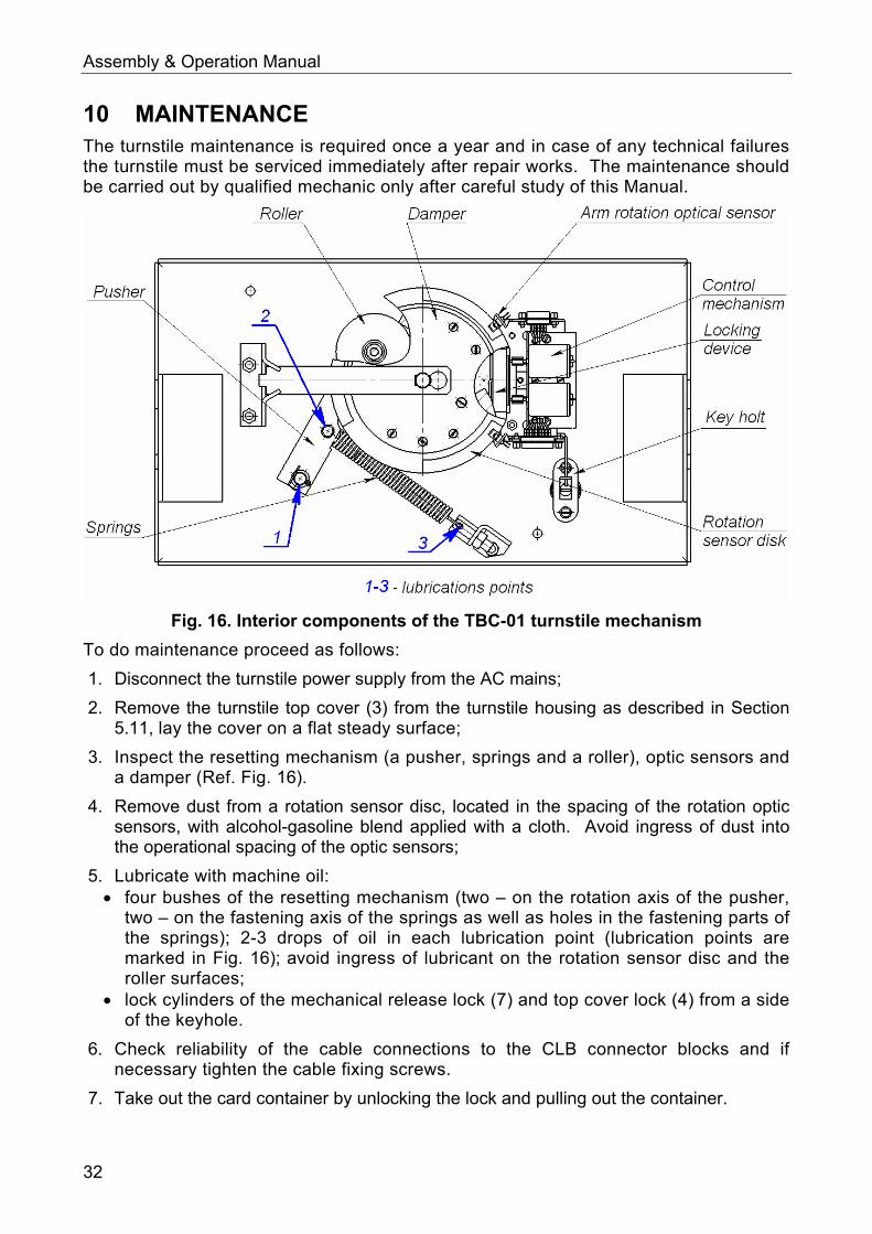
10 MAINTENANCE The turnstile maintenance is required once a year and in case of any technical failures the turnstile must be serviced immediately after repair works. The maintenance should be carried out by qualified mechanic only after careful study of this Manual.
Fig. 16. Interior components of the TBC-01 turnstile mechanism
To do maintenance proceed as follows:
1. Disconnect the turnstile power supply from the AC mains;
2. Remove the turnstile top cover (3) from the turnstile housing as described in Section 5.11, lay the cover on a flat steady surface;
3. Inspect the resetting mechanism (a pusher, springs and a roller), optic sensors and a damper (Ref. Fig. 16).
4. Remove dust from a rotation sensor disc, located in the spacing of the rotation optic sensors, with alcohol-gasoline blend applied with a cloth. Avoid ingress of dust into the operational spacing of the optic sensors;
5. Lubricate with machine oil: four bushes of the resetting mechanism (two – on the rotation axis of the pusher,
two – on the fastening axis of the springs as well as holes in the fastening parts of the springs); 2-3 drops of oil in each lubrication point (lubrication points are marked in Fig. 16); avoid ingress of lubricant on the rotation sensor disc and the roller surfaces;
lock cylinders of the mechanical release lock (7) and top cover lock (4) from a side of the keyhole.
6. Check reliability of the cable connections to the CLB connector blocks and if necessary tighten the cable fixing screws.
7. Take out the card container by unlocking the lock and pulling out the container.
32

TBC-01.1 Electromechanical Box Tripod Turnstile
8. Inspect thoroughly the card capture reader mechanism and make sure the electromagnet, shutters and reverse springs are properly fixed; tighten fastening when necessary; it is recommended to lubricate friction points with machine oil.
9. After inspection install the card capture reader into its operating position.
10. Check reliability of the barrier arm (5) fastening, to do so: unscrew the cover (6) screw M4×25 with a screw driver and take off the cover; tighten the M8×30 bolts of the barrier arms with the S13 socket wrench if
necessary; put the cover into its operating position and fix it with the screw.
11. Check reliability of the turnstile housing fastening to the floor and if necessary, tighten the anchor bolts with S17 socket wrench.
12. Return the top cover (3) into its operating position (Ref. Section 6); mounting of the housing top cover does not need much efforts: the top cover lock locks by pressing the lock cylinder without turning the key.
13. Check operation of the turnstile in accordance with Section 9 of this Manual.
14. After maintenance works are complete the turnstile is ready for further operation.
15. In case of any defects revealed during visual check please apply to the PERCo Technical Support Department (the PERCo TSD).
11 TRANSPORTATION AND STORAGE The turnstile in the original package should be transported in closed freight containers or other closed type cargo transport units.
During storage and transportation the boxes with the turnstiles can be stacked maximum 2 layers high.
Storage of the turnstile is allowed in dry indoor facilities at an ambient air temperature from -25°C to + 40°C at relative air humidity 80% at +25°C.
After transportation or storage at temperatures below zero or at high air humidity, prior to installation the turnstile must be kept in the original package for no less than 24 hours indoors under conditions corresponding to operation conditions (Ref. Section 2).
33

Assembly & Operation Manual
Appendix 1. Control signal algorithm in pulse control mode
Note: For the RC-panel: active front – pressing of the relevant button on the RC-panel; low level – the relevant button on the RC-panel has been pressed; high level – the relevant button on the RC-panel is not pressed.
The command is a signal active front (signal transfer from the high level to the low level) at any of the contacts at presence of the corresponding signal levels at the other contacts. The following commands can be formed by sending a low-level signal to the contacts Unlock A, Stop and Unlock B of the XT1.L connector block relatively to the contact GND:
Always locked (locked for entry and exit)
Active front is at the contact Stop while there is a high level at the contacts Unlock A and Unlock B. Both passage directions are locked at this command.
Single passage in the direction A (open for passage of one person in the direction A)
Active front is at the contact Unlock A while there is a high level at the contacts Stop and Unlock B.
At this command the passage direction A opens either for 5 sec. or until the passage has been made in this direction or until the command “Always locked” and the status of the passage direction B does not change at that. The command is ignored if at the moment of its receipt the status of the passage direction A is “Always free”.
Single passage in the direction B
Active front is at the contact Unlock B while there is a high level at the contacts Stop and Unlock A.
At this command the passage direction B opens either for 5 sec. or until the passage has been effected in this direction or until the command “Always locked”, and the status of the passage direction A does not change. The command is ignored if at the moment of its receipt the status of passage direction B is “Always free”.
Bi-directional single passage (open for one passage in each direction)
Active front is at the contact Unlock A while there is a low level at the contact Unlock B and a high level at the contact Stop,
or active front is at the contact Unlock B while there is a low level at the contact Unlock A and a high level at the contact Stop.
At this command the both passage directions open either for 5 sec. each or until the command “Always locked” is received. The command is ignored for the passage direction, which status at the moment of its receipt is “Always free”.
Free passage in the direction A (open for free passage in the direction A)
Active front is at the contact Unlock A while there is a low level at the contact Stop and a high level at the contact Unlock B,
or active front is at the contact Stop while there is a low level at the contact Unlock A and a high level at the contact Unlock B.
At this command the passage direction A opens until the command “Always locked” is received; the status of the passage direction B does not change at that.
34

TBC-01.1 Electromechanical Box Tripod Turnstile
Free passage in the direction B (open for free passage in the direction B)
Active front is at the contact Unlock B while there is a low level at the contact Stop and a high level at the contact Unlock A,
or active front is at the contact Stop while there is a low level at the contact Unlock B and a high level at contact Unlock A.
At this command the passage direction B opens until the command “Always locked” is received; the status of the passage direction A does not change at that.
Free passage (open for free passage in both directions)
Active front is at the contact Unlock A while there is a low level at the contacts Unlock B and Stop,
or active front is at the contact Unlock B while there is a low level at the contacts Unlock A and Stop,
or active front is at the contact Stop while there is a low level at the contacts Unlock A and Unlock B.
The both directions open at this command until the command “Always locked” is received.
Appendix 2. Control signal algorithm in potential control mode
Note for ACS controller outputs: low level – either contacts of the output relay are closed or the output transistor is open; high level – either contacts of the output relay are broken or the output transistor is closed.
Both directions are locked (locked for entry and exit)
There is a high level at the contacts Unlock A and Unlock B, or a low level at the contact Stop. The both passage directions lock at this command.
The direction A is open (open for passage in the direction A)
There is a low level at the contact Unlock A while a high level is present at the contacts Stop and Unlock B.
At this command the direction A opens till the low-level signal removal from the contact A or until the command “Both directions locked” is received. The status of the direction B does not change at that.
The direction B is open (open for passage in the direction B)
There is a low level at the contact Unlock B while there is a high level at the contacts Stop and Unlock A.
At this command the direction B opens till the low-level signal removal from the contact B or until the command “Both directions locked” is received. The status of the direction A does not change at that.
Both directions are open (open for entry and exit)
There is a low level at the contacts Unlock A and Unlock B while there is a high level at the contact Stop.
The both directions open at this command till the low-level signal removal from one of the contacts A (B) or until the command “Both directions locked” is received.
35

PERCo
Polytechnicheskaya str., 4, block 2 194021, Saint Petersburg
Russia
Tel: +7 812 247 04 64
E-mail: [email protected] [email protected]
www.perco.com

www.perco.com