performance comparison of different speed estimation
TRANSCRIPT
Performance comparison of different
speed estimation techniques in sensorless
vector controlled induction motor drives
VIKASH KUMAR (711EE2102)
Department of Electrical Engineering
National Institute of Technology, Rourkela

i
Performance comparison of different speed
estimation techniques in sensorless vector controlled
induction motor drives
A thesis submitted in partial fulfillment of the requirements for the degree of
B.Tech and M.Tech Dual Degree
In
Electrical Engineering
(Specialization: Power Control & Drives)
By
VIKASH KUMAR
Under the supervision of
Prof. K.B Mohanty
May, 2016
Department of Electrical Engineering
National Institute of Technology, Rourkela
ii
Prof. K.B Mohanty
Professor
May, 2016
Supervisor’s Certificate
This is to certify that the work presented in the dissertation entitled Performance comparison
of different speed estimation techniques in sensorless vector controlled induction motor drives
submitted by Vikash Kumar, Roll Number 711EE2102, is a record of original research carried
out by him under our supervision and guidance in partial fulfillment of the requirements of the
degree of B.Tech and M.Tech Dual Degree in Electrical Engineering with specialization in
“Power Control and Drives”. Neither this dissertation nor any part of it has been submitted
earlier for any degree or diploma to any institute or university in India or abroad.
Kanungobarada Mohanty
Professor
Department of Electrical Engineering
National Institute of Technology Rourkela

iii
Dedicated to my parents,
teachers and friends

Acknowledgment
The successful completion of the task I took would be incomplete without the special thanks
to those people whose guidance and support made this report to its real form.
I am greatly thankful to my guide Prof. Kanungo Barada Mohanty for his valuable
supervision and encouragement throughout the study. His supervision and valuable instructions
helped me in all aspects regarding the project work. I also express my gratitude to Prof. A. K.
Panda for his constant encouragement all through the research work.
I am grateful to all my classmates and the department research scholars for their
overwhelming help and cooperation during the project work.
I would like to express my heartfelt thanks to my beloved parents for their blessings, my
friends for their help and wishes for the successful completion of this dissertation report.
May, 2016
NIT, Rourkela
VIKASH KUMAR
Roll No – 711EE2102
v
ABSTRACT
Field-oriented control and direct torque control are fast becoming necessities of modern
industrial setups for induction motor drive control. Induction motors are considered as the
beginning part to create any electrical drive system to be subsequently utilized for several
industrial requirements. So now a day due to its high application the need to control the
performance of the induction motor is gaining importance. In modern control system, IM is
analyzed by different mathematical models mainly depending on its applications. Vector
control method is suitably applied to induction machine in 3-phase symmetrical or in 2-phase
unsymmetrical version. For vector control IM is realized as DC motor having its characteristics.
This dissertation work is aimed to give a detailed idea about the speed control and variations in
an induction motor through vector control technique thereby showing its advantage over the
conventional scalar method of speed control. It also focusses on the speed estimation techniques
for sensorless closed loop speed control of an IM relying on the direct field-oriented control
technique. The study is completed through simulations with use of MATLAB/Simulink block
sets allowing overall representation of the whole control system arrangement of the Induction
motor. The performance of different sensorless schemes and comparison between them on
several parameters like at low speed, high speed etc. is also provided emphasizing its
advantages and disadvantages. The analysis has been carried out on the results obtained by
simulations, where secondary effects introduced by the hardware implementations have not
been considered. The simulations and the evaluations of different control techniques are
executed using parameters of a 50 HP, 60 Hz induction motor which is fed by an inverter.

vi
CONTENTS SUPERVISOR’S CERTIFICATE……………………………………………………...…...ii
ACKNOWLEDGEMENT…………………………………………………………………...iv
ABSTRACT…………………………………………………………………………………...v
LIST OF FIGURES………………………………………………………………………...viii
ABBREVIATION……………………………………………………………………………ix
1 INTRODUCTION ..........................................................................................................1
1.1 Introduction ..............................................................................................................1
1.2 Need of electric drive ...............................................................................................2
1.3 Control principle ......................................................................................................4
1.4 Evolution of drives ...................................................................................................4
1.4.1 DC Drive ...........................................................................................................5
1.4.2 Scalar frequency Control ...................................................................................5
1.4.3 Field Oriented Control (FOC) ............................................................................5
1.5 Literature Review .....................................................................................................7
1.6 Objective ..................................................................................................................8
1.7 Dissertation Outline ..................................................................................................9
2 MODELLING & FIELD ORIENTED CONTROL OF INDUCTION MOTOR ............ 10
2.1 Introduction ............................................................................................................ 10
2.2 Induction motor modelling ..................................................................................... 10
2.2.1 Steady state modelling ..................................................................................... 10
2.2.2 Dynamic modelling of Induction machines ...................................................... 13
2.3 Induction machine control ...................................................................................... 16
2.4 Field Oriented Control ............................................................................................ 17
2.4.1 Direct Vector Control ...................................................................................... 19
2.4.2 Indirect Field Orientation Control .................................................................... 21
2.5 Conclusion ............................................................................................................. 23
3 SENSORLESS VECTOR CONTROL OF INDUCTION MOTOR ............................... 24
3.1 Introduction ............................................................................................................ 24
3.2 Speed Estimation Schemes ..................................................................................... 25
vii
3.2.1 Estimation of synchronous and slip speed ........................................................ 25
3.2.2 Direct synthesis of speed from state equations ................................................. 27
3.2.3 Model Reference Adaptive Systems estimator ................................................. 28
3.2.4 Adaptive Observer........................................................................................... 31
3.3 Conclusion ............................................................................................................. 32
4 SIMULATIONS AND RESULTS ................................................................................ 33
4.1 Introduction ............................................................................................................ 33
4.2 Vector Control Simulation Results ......................................................................... 33
4.2.1 Direct Vector Control ...................................................................................... 34
4.2.2 Indirect Vector Control .................................................................................... 35
4.2.3 Stator Oriented Control ................................................................................ 36
4.3 Sensorless Vector Control Simulation Results ........................................................ 36
4.3.1 Estimation of synchronous and slip speed ........................................................ 36
4.3.2 Direct synthesis of speed from state equations ................................................. 38
4.3.3 MRAS Estimator ............................................................................................. 39
4.3.4 Adaptive Speed Observer ................................................................................ 41
4.4 Performance comparison of Sensorless speed estimation schemes .......................... 41
4.4.1 Estimation of synchronous and slip speed ........................................................ 42
4.4.2 Direct synthesis of speed from state equations ................................................. 42
4.4.3 MRAS Estimator ............................................................................................. 43
4.4.4 Adaptive Speed Observer ................................................................................ 43
4.5 Conclusion ............................................................................................................. 43
5 CONCLUSION AND FUTURE SCOPE ...................................................................... 44
5.1 Conclusion ............................................................................................................. 44
5.2 Scope for future work ............................................................................................. 44
6 References .................................................................................................................... 45
7 APPENDIX .................................................................................................................. 47

viii
LIST OF FIGURES
Figure 1-1 Application of induction motor in flow control (IM runs at constant speed and flow is
controlled through Throttle) ................................................................................................................ 3
Figure 1-2 Application of induction motor in flow control (IM runs at variable speed to control flow) 3
Figure 1-3 Evolution of drives ............................................................................................................ 5
Figure 2-1Equivalent circuit of IM in steady state ............................................................................. 11
Figure 2-2 Vector Control Analogy .................................................................................................. 17
Figure 2-3 Block Diagram of FOC .................................................................................................... 18
Figure 2-4 Direct field oriented drive system .................................................................................... 18
Figure 2-5 Indirect field oriented drive system .................................................................................. 19
Figure 2-6 Direct vector control phasor ............................................................................................. 20
Figure 2-7Indirect vector control phasor ........................................................................................... 21
Figure 3-1 Vector control diagram .................................................................................................... 25
Figure 3-2 Synchronous speed estimation block ................................................................................ 25
Figure 3-3 Slip speed calculation ...................................................................................................... 26
Figure 3-4 Slip speed estimation scheme .......................................................................................... 28
Figure 3-5 MRAS based speed estimator .......................................................................................... 29
Figure 4-1 Speed Response of Direct Vector Control ........................................................................ 34
Figure 4-2 Torque Response of Direct Vector Control ...................................................................... 34
Figure 4-3 Waveform of stator current ,I I ................................................................................... 35
Figure 4-4 Waveform of Stator current , , ca bI I I ............................................................................. 35
Figure 4-5 Speed Response of Indirect Vector Control ...................................................................... 35
Figure 4-6 Speed Response of Stator Oriented Vector Control .......................................................... 36
Figure 4-7 Waveform of Stator Currents ,I I ................................................................................. 36
Figure 4-8 Speed Response of sensorless slip estimator scheme ........................................................ 36
Figure 4-9 Torque response of sensorless speed estimator scheme .................................................... 37
Figure 4-10 Waveform of Stator Currents ,I I ............................................................................... 37
Figure 4-11 Waveform of Stator Currents , , ca bI I I ........................................................................ 37
Figure 4-12 Speed response of open loop estimator scheme .............................................................. 38
Figure 4-13 Torque response of open loop estimator scheme............................................................. 38
Figure 4-14 Waveform of Stator Current ,I I ................................................................................. 39

ix
Figure 4-15 Waveform of Stator Current , , ca bI I I .......................................................................... 39
Figure 4-16 Speed response of MRAS .............................................................................................. 39
Figure 4-17 Torque response of MRAS ............................................................................................ 40
Figure 4-18 Waveform of Stator Current ,I I ................................................................................. 40
Figure 4-19 Waveform of Stator Current , , ca bI I I .......................................................................... 40
Figure 4-20 Speed Response of Adaptive Observer ........................................................................... 41
Figure 4-21 Speed Response of Slip Estimation Scheme ................................................................... 42
Figure 4-22 Speed Response of Open loop estimator........................................................................ 42
Figure 4-23 Speed Response of MRAS scheme ................................................................................ 43
Figure 4-24 Speed Response of Adaptive speed Observer ................................................................. 43

x
LIST OF SYMBOLS & ABBREVIATION
FOC Field oriented control
DTC Direct torque control
AC Alternating Current
r Rotor mechanical speed(rad/s)
*
r Reference or command speed (rad/s)
e Speed of the reference frame or synchronous
speed (rad/s)
sl Electrical slip speed (rad/s)
,dr qr d – axis and q – axis rotor flux linkages
,s s
dr qr Component of rotor flux linkage vector in
stationary (𝛼-β) reference frame
,s s
ds qs Component of stator flux linkage vector in
stationary (𝛼-β) reference frame
𝐼a∗,𝐼b∗,𝐼c∗ Reference current for abc phase of inverter
Td Electromagnetic torque developed by motor
TL Load torque
,ds qsv v d and q – axis stator voltages
Rs ,Rr Resistance per phase of stator and rotor
referred to stator
𝐿𝑠,𝐿𝑟 Stator and rotor per phase inductance
referred to stator
Lm Magnetizing inductance per phase referred
to stator
f Supply frequency in Hz
J Polar moment of inertia of the motor
X State vector
Y Output vector
1
CHAPTER 1
1 INTRODUCTION
1.1 Introduction
Induction machine possesses many significant advantages in comparison to several numerous
different types of electrical machines. Induction machine is valued so much because they are
inexpensive and rugged. They don’t require periodic maintenance and don’t possess brushes
like Direct control (DC) machines and their packed structure makes then impervious to different
environment conditions. Therefore, in the present scenario much importance is provided to
controlling methods of induction machines but owing to their complex mathematical model and
given non-linearity, an IM requires more sharp control technique as in comparison to DC
motors. For several decades, open loop v/f control technique which alter itself to uniform volts-
per-Hertz proportion of stator voltage has been implemented. But owing to unsatisfactory
dynamic results of this given type of control method resulting in saturation effect along with
the variation of electrical parameter with temperature has forced to turn to other control
techniques. Now a days brisk and swift switching semiconductor power switches available in
power electronics and their improvement in power loss have paved the way for powerful digital
signal processors on controller technology which are really fast to be applied for advanced
control techniques of IM drives.
In the drive applications it has been the dream to run squirrel cage induction motor as a
conventional separately excited dc motor and give the desired performance. Despite the latest
researches in Vector control/Field oriented control (FOC) there is high room for improvement
as there we have not been quite able to bridge the gap between the dream and reality. Although
Direct Torque Control has further simplified the Control circuitry to a greater extent. The
availability of cheap microprocessors coupled with advancement in Artificial Intelligence (AI),
Genetic Algorithm (GA), Fuzzy Logic (FL) etc. have really influenced the design, monitoring
and operation of modern industrial electric drives.
A lot of studies in the last decade and so has been put to test to iron out several diverse possible
solutions of IM drives control with sole objectives of quick and accurate torque and flux control
Chapter 1 Introduction
2
along with the reduction of the algorithms complexity involved in FOC etc. This chapter
presents brief idea about the Necessity of electric drives, Basic control principles and their
classification along with evolution of electric drives. A brief introduction to the FOC has been
given in present chapter which is the main focus of the dissertation work.
1.2 Need of electric drive
There are numerous issues which are involved in the driving of the induction machine.
Previously motors were designed for only driving specific loads i.e. maximum times the
generated torque was greater than the required load torque, which as a result provided
inefficient driving system as it led to substantial amount of power loss. As we know the in the
induction machine the steady state operating region lies in the range of 80% to 100% of the
rated speed because of constant supply frequency and fixed number of poles. During starting,
the absence of back emf allows the IM to draw a very high amount of inrush current resulting
in high power loss and can occasionally cause insulation failure of burning of the motor parts.
The performance of the other electrical appliances in the same line can similarly be affected
because it causes high voltage dip in the supply line. The power factor of induction machine is
quite low (as low as 0.1) at light load (i.e. open shaft) condition. The main reason is that at light
load IM draws highly inductive current. Although with gradual increase in load power factor
improves as it increases thereafter. When induction machine runs at less than unity power
factor, the current withdrawn is non- sinusoidal in nature which lowers the supply line power
quality and degrades performance of several other utilities connected to the same line. Now a
day’s distribution company penalizes those customers who draws power at lower PF than
specified. Also, an induction motor which is operating at lower PF draws currents which are
rich in harmonics causing higher rotor loss affecting motor life and thus may lead to pulsating
torque resulting in jerky motion affecting the life of motor bearings and may lead to permanent
failure of system.
In applications like hoist, crane etc. it often becomes necessary to stop and reverse quickly. It’s
evident that quality and productivity of the system could be improved by improving the
accuracy of stopping and reversing operation. Earlier mechanical brakes were mainly used for
all of the stopping and reversing operation of the IM, which were insufficient as they require
continuous maintenance. A lot of the other important application of IM like fan, blower, pump
Chapter 1 Introduction
3
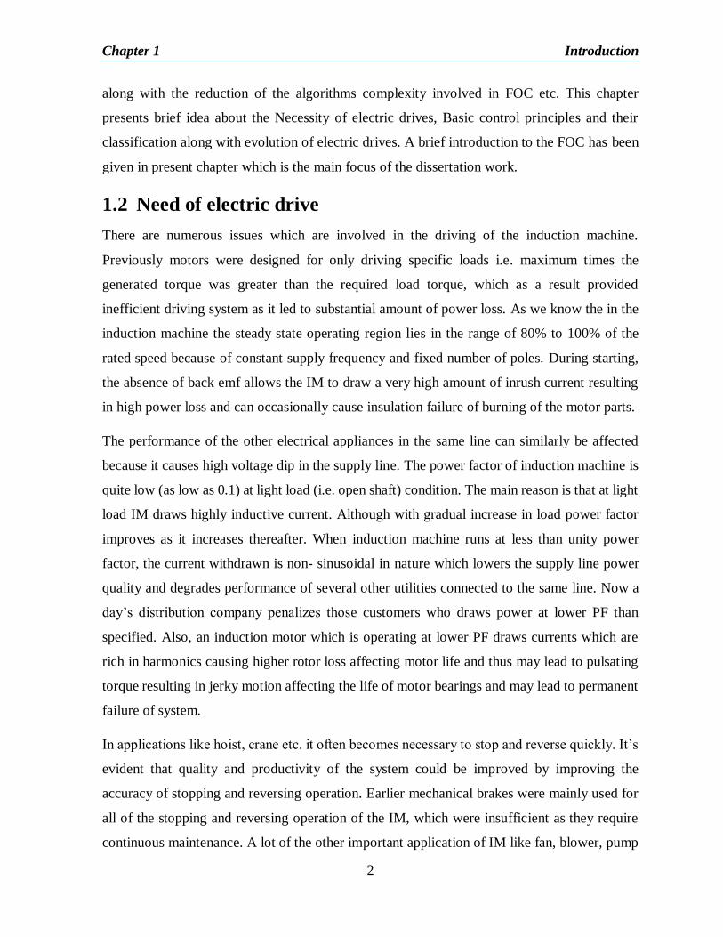
etc. often need to control speed too. Consider the figure 1.1 and 1.2 in these type of loads, the
torque and power is related to speed as:
2
1( )Torque k speed and 3
1( )Power k speed
Figure 1-1 Application of induction motor in flow control (IM runs at constant speed and flow
is controlled through Throttle)
Figure 1-2 Application of induction motor in flow control (IM runs at variable speed to control
the flow)
Hence, depending upon the load Variable speed control could provide good amount of energy
saving. As can be seen from the above expressions that with reduction of 20% in the operating
speed will eventually amount to 50% reduction in the input power to the induction machine.
However, it can’t not be possible for those systems in which motor is connected directly to the
supply in place of being connected to line through a power converter. Thus Fig 1.2 can be
understood as an appreciable power saving scheme.

Chapter 1 Introduction
4
Thus inferring from the previously mentioned points, the need for intelligent motor control can
be understood. Hench with advancement in solid state devices (SSD) technology like IGBT,
BJT, SCR, MOSFET etc. and technologies like IC fabrication technology, microcontrollers,
microprocessors, AI methods which are capable of executing real-time complex algorithms it
is now possible to realize Intelligent drive control.
1.3 Control principle
The speed of Induction machine can be demonstrated in terms of slip, frequency and pole
numbers as: 4
(1 ) (1 )sm s
fs s
P
The speed of the IM rotor can be varied or controlled by changing slip, frequency and the
number of poles. Changing the pole numbers is done by pole amplitude modulated motors
which is mainly achieved with a change in winding connections which requires relays and
circuit. The variation of applied voltage or insertion of external resistors in stator or rotor affects
the slip speed control. The inverter-driven induction motor with the help of variable frequency
operation achieves speed control. To keep the air gap flux constant not only the frequency but
the applied voltage also needs to be varied which further doesn’t let it saturate. A number of
speed control strategies have been implemented by modern age variable frequency drive (VFD)
which remains the main aim of this dissertation and will be discussed in further sections.
1.4 Evolution of drives
The motivation behind the evolution of drives from DC to various form of AC drives has been
driven by continuous need of reliability, simplicity, performance, ruggedness, cost and
availability. In practice, these needs have often resulted in covering mutually specific goals.
New research now a day often bring out techniques with certain advantages and disadvantages.
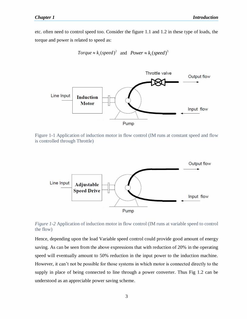
Figure 1.3 shows evolution of basic drives as for assessment purposes this viewpoint is simple
and useful.
Chapter 1 Introduction
5
Figure 1-3 Evolution of drives
1.4.1 DC Drive
One of the significant advantage of DC drive is that both direct flux and direct torque control
are available. In a dc motor flux is controlled by field control and armature current controls the
motor torque. A PWM inverter which is connected at its terminal provides the required flux and
voltage to control the torque and speed. The poor accuracy control results due to absence of
encoder and field orientation. Even if it’s simpler in construction and possesses low cost but it
provides very poor performance and less accuracy.
1.4.2 Scalar frequency Control
A block diagram for the scalar control has been shown in figure 1.4. Although, this type of
drives uses all the advantages of IM but torque and flux neither directly nor indirectly could be
controlled. A PWM invertor connected at its terminal provides the require voltage and flux to
control speed and torque. The accuracy of control is very poor due to absence of encoder and
field orientation. Although it has simple construction and low cost but it provides very less
accuracy and poor performance.
1.4.3 Field Oriented Control (FOC)
The most familiar control scheme used for induction motor drive control is the field oriented
control (FOC). This control comprises of stator currents being controlled and represented by a
vector. FOC control scheme is mainly based on the principles which transform a 3-phase time
as well as speed dependent system into a 2 coordinate system (d and q) which are time invariant
system. The major idea behind the vector control of IM is to have an electric drive which
possesses superior performance than separately excited DC motor. The squirrel cage induction

Chapter 1 Introduction
6
motor with FOC shows a good level of dynamic performance and stability of the system is a
long term phenomenon through the closed loop control of this drive. FOC is separately called
‘Independent or Decoupled control’ wherein flux and torque current vectors are controlled. In
the field control stator current are expressed in the rotating coordinate system and are further
resolved into two components which produce the torque and flux in the motor and are
orthogonal in nature. This arrangement is similar to the DC motor in which flux and torque are
controlled independently. To control flux and torque (thereby speed) independently in the
induction machine, there is necessity to control the phase and magnitude of three phase stator
currents with the help of fast inverter like CC-VSI (current control voltage source inverter).
These control algorithms are highly complex and involved and to realize this aim fast acting
microcontrollers and other processors are used.
The main disadvantage of Field oriented control is compulsory use of ‘Encoder”. The process
of voltage and frequency reference takes good amount of time, thereby limiting the ability to
achieve rapid flux and torque. In the FOC for rotor flux regulation, flux position is also required,
which is either sensed or estimated. Speed and flux estimation are the main problems of the
field orientation in the recent years. The induction machine drive without the speed sensors give
the advantage of low cost and high reliability. Estimation of magnitude and spatial orientation
of flux in the stator or rotor is also necessary for such type of drives.
Rotor flux orientation is mainly categorized in two parts which are the direct field orientation
relying on measurement and direct measurement of rotor magnitude and angle and other being
the indirect orientation in which slip speed relation is utilized. The scenario of Indirect field
orientation is a feedforward approach and is very much sensitive to parameters particularly to
the rotor time constant. Due to this several parameter adapting strategies have been developed
[8].
Direct field oriented control (DFOC) utilizes the flux angle Ɵe which is obtained or calculated
by sensing the air gap flux with the help of flux sensing coils. This arrangement adds to the
complexity and the cost of the drive system. So for the last decades many different type of
algorithms has been proposed to avoid the use of these flux sensors on the induction machine
drive systems to estimate both the rotor flux vector and rotor shaft speed. The most recent trend
Chapter 1 Introduction
7
can be directed toward the use of speed sensors and using algorithms based on the terminal
quantities of the machine for the estimation of the fluxes.
One of the preferred flux and speed estimation technique (algorithm) is saliency based with
fundamental or high frequency signal injection. The advantage that this saliency based method
offers is that the saliency is not sensitive to actual motor parameters. Although this method also
suffers of insufficient performance at low and zero speed level. Also when it is subjected to
high frequency signal injection this method has shown to cause torque ripples, audible noise
and vibration.
1.5 Literature Review
Now a day for industrial applications induction machines associated with high performance
drives are used. The history of inductions machines as well as uses have been quite broad. It
finds numerous use in commercial, industrial and domestic applications as adjustable speed
drives. In present section a literature review has been presented as a means to show the
exploration and work of several researchers to make Induction machine very precise, quick and
of high performance. A lot of work has been done to develop the technique and to reach the
best efficiency of induction motor drive (IMD), many new techniques of control has been
developed in the last few years.
Almost 40 years ago, very first paper, in 1971 F. Blaschke [1] presented field oriented control
(FOC) of induction motor. A lot of work has been done after that time to develop the technique
as now a days FOC drives are an industrial reality and are readily available in the market
manufactured by different companies with desired performance and other requirements.
In recent decades much effort has been made to get rid of conventional speed transducer from
its use in adjustable induction motor drives. By making the use of voltage and current this aim
has been fulfilled. A very good effort was made by Brennen and Abbondanti in 1975 in form
of an analog slip calculator which was based on the processing of the motor quantities such as
current and voltage [2].In 1979 the same work on sensorless technique was highlighted by
Ishida et al [3] who made the use of rotor slot harmonic voltages in slip frequency control.
Chapter 1 Introduction
8
William L. Erdman and R. G. Hoft in 1990 described airgap and stator field orientation (FOC)
methods as an alternative to the familiar rotor orientation process. The advantages of stator and
airgap decoupling lie principally in estimating or measuring the corresponding flux. The airgap
flux is directly measurable, and the stator flux is closely related to stator terminal quantities.
The rotor flux is the most difficult to estimate and for this reason, stator and/or airgap flux
implementations may be more robust under parameter and environmental disturbances [4].
Several years later, in 2003 S. Xepapas presented a way for estimation of rotor speed, rotor flux
and its angular position as well as the motor torque from the measured terminal currents and
voltages. It used nonlinear sliding control technique for control at both low and high speeds [5].
Thereafter Ahmad Razani Haron, Nik Rumzi Nik Idris, in 2006 discussed the performance of
the rotor flux based MRAS (RF-MRAS) and back e.m.f based MRAS (BEMF-MRAS) for
estimating the rotor speed. Both schemes use the stator equation and rotor equation as the
reference model and the adjustable model [6].
M. S. Zaky, M. Khater, H. Yasin, and S. S. Shokralla in 2008 discussed about study of the
different speed estimation techniques and their corresponding merits and demerits as well as
their feasibility for estimating the rotor speed. Many factors remain important to evaluate the
effectiveness of the different schemes proposed for speed estimation. Among them are steady
state error, dynamic behavior, noise sensitivity, low speed operation, parameter sensitivity,
complexity, and computation time [7].
The proposed method in [14] estimates the velocity without the assumption that the speed varies
slowly compares to electrical variables studied on non-linear method. So two estimator was
constructed: main flux estimator and complementary flux estimator. The main flux estimator
did not guarantee convergence for all the operating conditions. So start up complementary
estimator is used in such operating conditions. In this method significant sensitivity to
parameter uncertainty is observed.
1.6 Objective
The main aim of the project is to compare the performance of different sensorless vector
controlled IM drives and provide a detailed study regarding different speed estimation
methods and then their corresponding merits and demerits along with their feasibility to
estimate speed of the rotor. The simulation study of results forms the basis of the conclusion

Chapter 1 Introduction
9
1.7 Dissertation Outline
The dissertation has been organized as described below:
Chapter 1 deals with the brief idea about the introduction, need, principle, classification and
evolution of the variable frequency electric drives as well as the literature review and a short
and brief introduction of the FOC.
Chapter 2 includes the induction machine modelling and dynamical model of machine. This
can be implemented to materialize various other equivalent models in difference frame of
reference. Vector control technique of IM along with the direct and indirect control technique
has been explained.
Chapter 3 is devoted to the various speed estimation methods for sensorless direct field oriented
control of the Induction machine. MRAS speed estimator, open loop speed estimator along with
adaptive observer has been described.
Chapter 4 demonstrates the simulations of the vector control techniques along with various
sensorless speed estimation techniques for analyzing the comparison between there
performance.
Chapter 5 shows the performance comparison of these techniques and the preference on these
techniques in various conditions. There is include proposal for further research work.

Chapter 2 Modelling & Field oriented control of induction motor
10
CHAPTER 2
2 MODELLING & FIELD ORIENTED
CONTROL OF INDUCTION MOTOR
2.1 Introduction
Induction machine with rotor cage configuration have always been the widely used machine at
a particular fixed speed because of its efficiency, simplicity, reliability, ruggedness,
compactness, low cost, and having economical and volume manufacturing advantage. Although
in the recent year several developments regarding the field of varying speed drives have opened
up possibility of application of variable speed induction motor drives at a larger scale. In
comparison to separately excited DC motor Induction machine demands the use of extra
complex control techniques because of its structure having nonlinear dynamic structure with
strong coupling.
Now any power electronics drive e.g. Induction motor drive, controllers are needed to control
the system. This scenario requires mathematical modelling of the drive because of multivariable
nature of the systems and its higher order nonlinearity. Thus design and development of the
power electronics drive systems could be done by suitable mathematical modelling of the plant.
The induction motor modelling is mostly performed by a 3-phase (a-b-c) to synchronously
rotating (d-q) transformation with rotor flux linkages and stator current as the stator variables
neglecting saturation.
2.2 Induction motor modelling
2.2.1 Steady state modelling
The steady state equivalent circuit of an IM is very much identical to a transformer. With
simple mathematical manipulation it is integrated into the circuit despite rotor currents being
at slip frequency. An equivalent circuit (stator side referred) of induction motor is shown as in
figure 2.1

Chapter 2 Modelling & Field oriented control of induction motor
11
Figure 2-1Equivalent circuit of IM in steady state
Steady state performance equation:
In this scenario the no-load current is viewed as the sum of the core-loss components and the
magnetizing component of the current and accordingly is written as:
o m cI I I (2.1)
The magnetizing current in terms of the magnetizing reactance and air gap voltage is written
as:
1m
m
EI
jX (2.2)
Here, Xm is the magnetizing reactance and E1 is the airgap voltage
Similarly, core loss component of the stator current is written as:
1c
c
EI
R (2.3)
Where, Rc is the core loss accounting resistance
The rotor phase current is given by:
1r
rlr
EI
RjX
s
(2.4)
Where, Ir is phase current of rotor
Then the phase current of stator is:
as r oI I I (2.5)

Chapter 2 Modelling & Field oriented control of induction motor
12
In terms of stator parameters, stator current and induced emf the applied stator voltage is shown
as the sum of the induced emf with the stator impedance voltage drop which is given as:
1 ( )as s s asV E R jX I (2.6)
Where Vas is the stator phase voltage
The main variables in the machine comprise of air gap power, torque, mechanical and shaft
output. The difference among the total input power with respect to copper losses in stator is
expressed as real power transmitted from input to the air gap which is given as:
23a i as sP P I R (2.7)
Neglecting the core losses, we have
23 ra r
RP I
s (2.8)
Which could be written alternatively as
2 2 (1 )3 3a r r r r
sP I R I R
s
(2.9)
The Power Output Pm (mechanical) is given as:
2 (1 )3m r r
sP I R
s
(2.10)
Alternatively, it can also be given in form of electromagnetic torque and rotor speed as:
m e mP T (2.11)
Where Te is the internal or electromagnetic torque
23 (1 )r r
e
m
I R sT
s
(2.12)
Substituting for the motor speed in terms of the slip and stator frequency,
(1 )
2 2
srm
s
P P
(2.13)
The electromagnetic or air gap torque is obtained as:
2
3( 2) r re
s
I RT P
s (2.14)
The net output power of the machine Ps:
Chapter 2 Modelling & Field oriented control of induction motor
13
s m fwP P P (2.15)
The friction and the windage losses are two different losses as they are proportional to the speed
and the square of speed respectively. Therefore, for evaluation of variable speed performance
of IM they have to be represented as function of speed. There are also other type of losses such
as stray load losses which are caused due to stray magnetic fields in the machine.
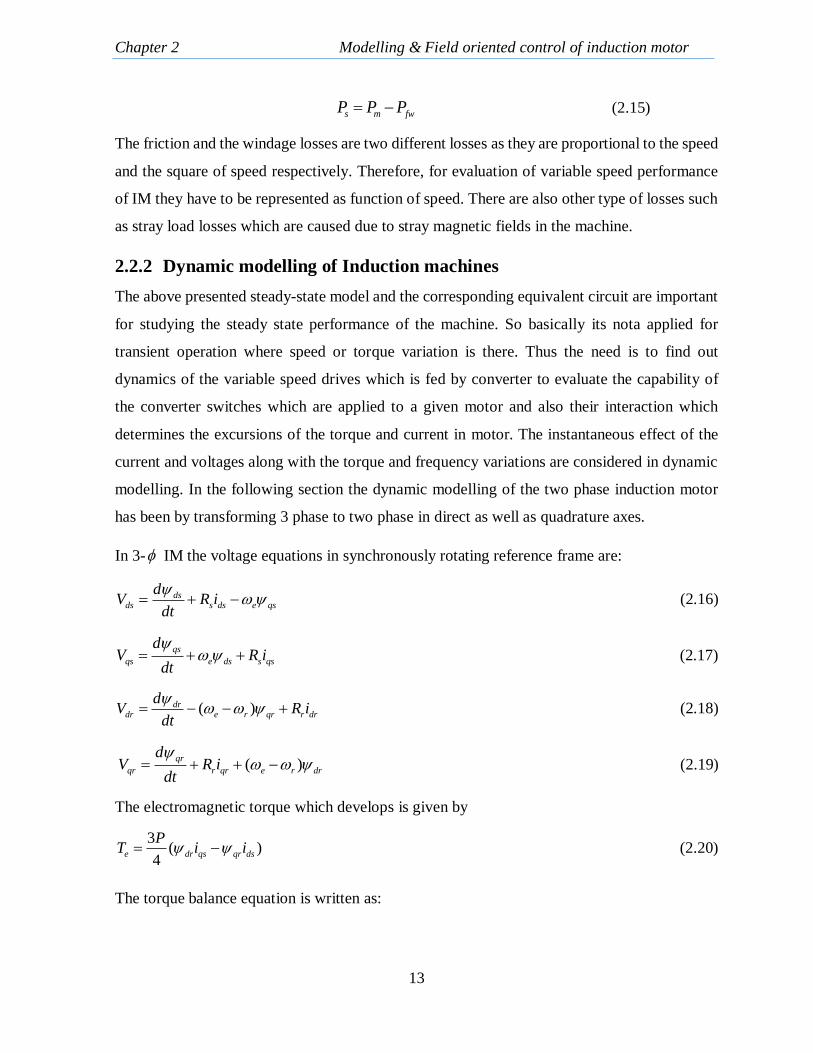
2.2.2 Dynamic modelling of Induction machines
The above presented steady-state model and the corresponding equivalent circuit are important
for studying the steady state performance of the machine. So basically its nota applied for
transient operation where speed or torque variation is there. Thus the need is to find out
dynamics of the variable speed drives which is fed by converter to evaluate the capability of
the converter switches which are applied to a given motor and also their interaction which
determines the excursions of the torque and current in motor. The instantaneous effect of the
current and voltages along with the torque and frequency variations are considered in dynamic
modelling. In the following section the dynamic modelling of the two phase induction motor
has been by transforming 3 phase to two phase in direct as well as quadrature axes.
In 3- IM the voltage equations in synchronously rotating reference frame are:
dsds s ds e qs
dV R i
dt
(2.16)
qs
qs e ds s qs
dV R i
dt
(2.17)
( )drdr e r qr r dr
dV R i
dt
(2.18)
( )qr
qr r qr e r dr
dV R i
dt
(2.19)
The electromagnetic torque which develops is given by
3( )
4e dr qs qr ds
PT i i (2.20)
The torque balance equation is written as:
Chapter 2 Modelling & Field oriented control of induction motor
14
re l r
dT T J
dt
(2.21)
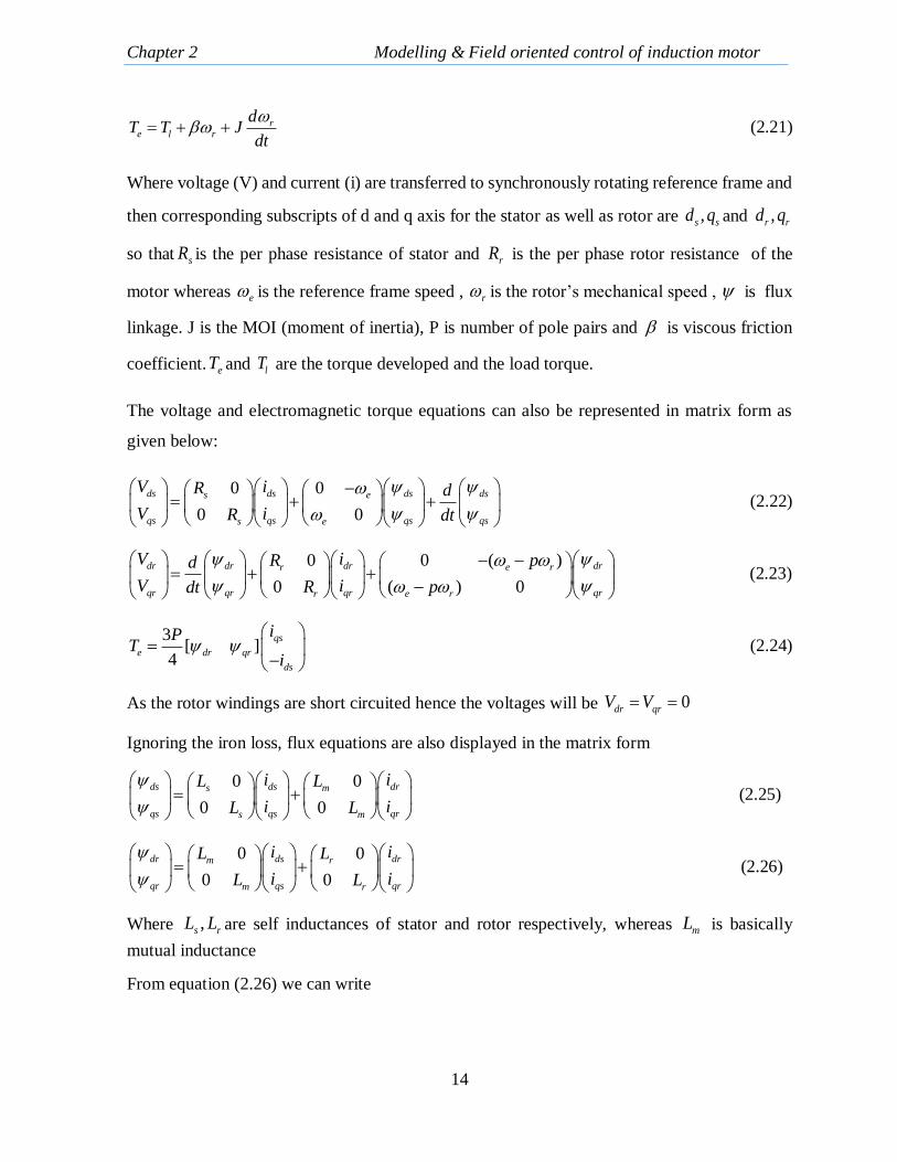
Where voltage (V) and current (i) are transferred to synchronously rotating reference frame and
then corresponding subscripts of d and q axis for the stator as well as rotor are ,s sd q and ,r rd q
so that sR is the per phase resistance of stator and rR is the per phase rotor resistance of the
motor whereas e is the reference frame speed , r is the rotor’s mechanical speed , is flux
linkage. J is the MOI (moment of inertia), P is number of pole pairs and is viscous friction
coefficient. eT and lT are the torque developed and the load torque.
The voltage and electromagnetic torque equations can also be represented in matrix form as
given below:
0 0
0 0
ds ds ds dss e
qs qs qs qss e
V iR d
V iR dt
(2.22)
0 ( )0
( ) 00
dr dr dr dre rr
qr qr qr qre rr
V i pRd
V i pRdt
(2.23)
3[ ]
4
qs
e dr qr
ds
iPT
i
(2.24)
As the rotor windings are short circuited hence the voltages will be 0dr qrV V
Ignoring the iron loss, flux equations are also displayed in the matrix form
0 0
0 0
ds ds drs m
qs qs qrs m
i iL L
i iL L
(2.25)
0 0
0 0
dr ds drm r
qr qs qrm r
i iL L
i iL L
(2.26)
Where ,s rL L are self inductances of stator and rotor respectively, whereas mL is basically
mutual inductance
From equation (2.26) we can write

Chapter 2 Modelling & Field oriented control of induction motor
15
10 0
10 0
m
dr dr dsr r
qr qr qsm
r r
L
i iL L
i iL
L L
(2.27)
Substituting equation (2.27) in (2.25)
00
00
m
ds ds drrs
qs qs qrs m
r
L
i LL
iL L
L
(2.28)
Where 2
1 m
s r
L
L L = leakage coefficient
Taking the rotor voltages zero and substituting (2.27) in (2.23) we get
0 00 ( )
( ) 000
r m r
dr ds dr drr r e r
qr qs qr qre rr m r
rr
R L R
iL L pd
i pR L Rdt
LL
5 4
5 4
0
0
dr ds drsl
qr qs qrsl
ia ad
ia adt
(2.29)
Where 5 4,r m r
r r
R L Ra a
L L and sl r ep
Taking equations (2.28), (2.22) and (2.29) we can find
1 2 3
1 3 2
0
0
ds ds dr dse r
qs qs qr qse r
i i va a pa cd
i i va pa a cdt
(2.30)
Where
2
1 2
1( )m
s r
s r
La R R
L L
2
2 2
1 mr
s r
La R
L L
3m
s r
La
L L ,
1
s
cL

Chapter 2 Modelling & Field oriented control of induction motor
16
Relating equations (2.29) and (2.30) we get the state space model of induction motor as:
1 2 3
1 3 2
5 4
5 4
0
0
0 0 0
00 0
ds dse r
qs qs dse r
qssldr dr
slqr qr
ci ia a pa
ci i va pa ad
va adt
a a
(2.31)
The electromagnetic torque can similarly be written in state space variables as
3[ ]
4
qs
e dr qr
ds
iPT
i
(2.32)
2.3 Induction machine control
The induction machine drives speed control requires the use of controllers which can be traced
to two major types of control: scalar control and vector control. Scalar control includes several
way of speed control techniques one of most used being the volts per hertz i.e. v/f control which
are of low cost conventionally. In this control, the voltage as well as frequency magnitude are
kept in regular proportion. But v/f control performances has been not been found satisfactory
because the rate of voltage change as well as frequency is needed to be kept low. Any sudden
change in deceleration or acceleration of the frequency or voltage lead to a transient current
change, which later leads to severe problems. Although many concrete works and
manipulations have been made to control performance of v/f method, still not any of those
improvements could provide an effective v/f controlled drive system and so this limitation
allowed the DC motor undisputed & permanent choice in case of various variable speed
requirements. This scenario started changing when the concept regarding field orientation
theory was suggested by Hasse and Blaschke. The complications are much more in field
oriented control than the control of DC motor. Even as the most successful class of the
controllers which are very popular use vector control method as it regulates magnitude and the
phase of AC excitation. So the given particular method results in particular space orientation of
field and torque which are orthogonal in nature and are thus called Field Oriented Control
(FOC).
Chapter 2 Modelling & Field oriented control of induction motor
17
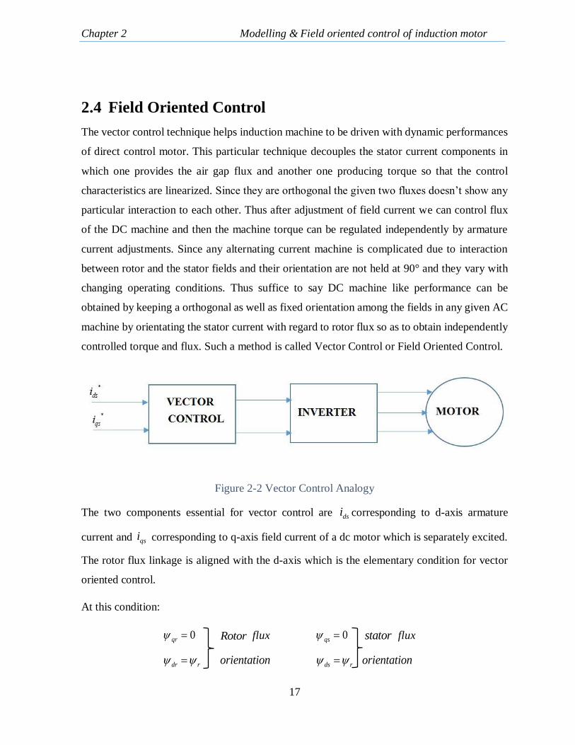
2.4 Field Oriented Control
The vector control technique helps induction machine to be driven with dynamic performances
of direct control motor. This particular technique decouples the stator current components in
which one provides the air gap flux and another one producing torque so that the control
characteristics are linearized. Since they are orthogonal the given two fluxes doesn’t show any
particular interaction to each other. Thus after adjustment of field current we can control flux
of the DC machine and then the machine torque can be regulated independently by armature
current adjustments. Since any alternating current machine is complicated due to interaction
between rotor and the stator fields and their orientation are not held at 90° and they vary with
changing operating conditions. Thus suffice to say DC machine like performance can be
obtained by keeping a orthogonal as well as fixed orientation among the fields in any given AC
machine by orientating the stator current with regard to rotor flux so as to obtain independently
controlled torque and flux. Such a method is called Vector Control or Field Oriented Control.
Figure 2-2 Vector Control Analogy
The two components essential for vector control are dsi corresponding to d-axis armature
current and qsi corresponding to q-axis field current of a dc motor which is separately excited.
The rotor flux linkage is aligned with the d-axis which is the elementary condition for vector
oriented control.
At this condition:
0qr Rotor flux 0qs stator flux
dr r orientation ds r orientation

Chapter 2 Modelling & Field oriented control of induction motor
18
Considering the above scenario, the block diagram for vector control can be shown as follows:
Figure 2-3 Block Diagram of FOC
The angle Ɵ can be obtained by indirect field orientation control (IFOC) or otherwise also by
direct field orientation control (DFOC). Henceforth controllers which are applied in this
scenario insures that it can obtain the decoupled torque and flux control and thus are known as
field oriented controller.
Figure 2-4 Direct field oriented drive system

Chapter 2 Modelling & Field oriented control of induction motor
19
Both different techniques of vector control named direct and indirect field oriented control
depend upon the basic flux acquisition method.
2.4.1 Direct Vector Control
The use of particular flux coils and sensors can be discontinued by estimation of the rotor flux
from the stator terminal quantities which are voltage and currents [9]. Direct method includes
the measurement of airgap flux directly incorporating the help of search coils. Sensors or
sensors, taped stator windings or it can be done by measurement from machine terminal
variables such as stator current, voltage and speed. Now the impossible scenario of direct
sensing procedure of rotor flux directs it to be obtained from the directly sensed airgap flux.
Rotor flux angle is measured directly through flux measurement and estimation. The very
serious drawback of this direct scheme arises is at low speed when the IR drop of the machine
is dominating which is difficult to neglect and it also the requirement of integration of signal
makes the measurement of airgap flux difficult. This thinking procedure requires the knowledge
of stator as well as rotor leakage inductances, magnetizing inductances and there is also need
of stator resistance. This procedure is normally referred as Voltage Model Flux Observer
(VMFO). Hence in stationary frame the stator flux can be obtained by the equations:
s
s s
qs qs s qsV r i
(2.33)
s
s s
ds ds s dsV r i
(2.34)
Figure 2-5 Indirect field oriented drive system

Chapter 2 Modelling & Field oriented control of induction motor
20
Also the rotor flux can be obtained as:
( )s s srdr ds ds
m
LL i
L (2.35)
( )s s srqr qs qs
m
LL i
L (2.36)
Where 2( / )s m rL L L L is the transient
leakage reactance
Voltage Model Flux Observer uses the measured current and voltages of the stator and requires
a pure integration without the use of any feedback. Thus it is found harder to be implemented
for frequencies of low excitation because of offset also and initial condition problems. Thus in
actual practice low pass filter is also used often to give stability due to the lack of filter which
is necessary for convergence. Accuracy of this model is totally independent to rotor resistance
but is found as being most sensitive with respect to stator resistance particularly at low
velocities. At high speed the stator resistance (IR) drop sensitivity to speed voltage is low which
reduces sensitivity to stator resistance. The sensitivity to the parameters study depicts that
leakage inductance very much affects the performance of the system in regard to dynamic
response, stability and utilization of inverter and the machine.
To overcome these difficulties caused by leakage inductance changes and also due to stator
resistance mainly at low speed as an alternative approach Current Model Flux Observer
(CMFO) has been proposed.
This flux model can be measured or estimated as:
1
s
s s smdr dr r qr ds
r r
Li
T T
(2.37)
1
s
s s smqr qr r dr qs
r r
Li
T T
(2.38)
Figure 2-6 Direct vector control phasor

Chapter 2 Modelling & Field oriented control of induction motor
21
This current model uses the stator current which is measured and speed of the rotor. The
dependency on speed of the current model is considered as disadvantage as this implies that
although use of the estimated flux obviously eliminates the flux sensor, the requirement of
position sensor is still there. Furthermore, even at low or zero speed operation rotor flux
magnitude response is sensitive to particularly to the rotor resistance, the phase angle is
insensitive to all the parameters. Near rated slip, both the quantities are particularly sensitive to
magnetizing inductance and resistance of the rotor. In the whole speed range the rotor leakage
resistance totally has no effect on accuracy.
2.4.2 Indirect Field Orientation Control
The indirect field orientation of the IM, the rotor vector dr instantaneous speed is same as
that of the synchronous speed e and as that of d-q coordinate system where d axis is directly
locked on the rotor flux vector as has been case for rotor flux vector orientation. This scenario
helps to control the flux by magnetizing current dsi through alignment of total flux with the d
axis and also aligning the other torque generating current component with q axis. Henceforth
after decoupling of the torque producing and the rotor flux currents the torque can be easily
regulated with the current qsi .
The rotor angle is found out with use of these described
equations:
*0 r mr
dr dr ds
r r
R LR di
L dt L
1
mdr ds
r
Li
T s
0 ( )r qr e r drR i mqr qs
r
Li i
L
*
*
r msl qs
r dr
R Li
L
(2.39)
Figure 2-7Indirect vector control phasor

Chapter 2 Modelling & Field oriented control of induction motor
22
( )e e r sl r sldt dt (2.40)
The Indirect field oriented control is a feedforward control which is basically open loop control
and in this method the slip frequency is fed forward which very much guarantees the field
orientation. This particular controlling operation is sensitive to rotor open circuit time constant
r which has to be known for achieving a decoupled control of flux and torque components by
control of the currents. When r is not set correctly, the machine is described as detuned and
its performance becomes very sluggish because of decoupled control loss. Hence, the
measurement of the time constant of the rotor, its effects on the system performance along with
its adaptive tuning with the variations which mainly result during the machine operation have
been extensively studied and monitored. The rotor time constant is also affected by the changes
in temperature which affects the torque capability of the induction motor. This effect of
detuning becomes of high severity mainly in the field weakening region. It also gives results as
steady state error and transient oscillation in the rotor torque and flux.
Thus the concept of indirect field orientation was developed and studied by many researchers
in last two-three decades. The indirect control is the most original and dominant choice for the
rotor flux orientation. Also the IFO control can be simulated or implemented using stator
orientation or the air gap flux as well. In air gap orientation the flux as well as slip relations are
coupled equations. In this case d-axis current does not control the flux independently as done
earlier in orientation along rotor flux. It has been found that in case of orientation along air gap
flux, the maximum produced torque is 20% lesser in comparison to the other methods.
Particularly in the scenario of orientation along stator flux, the transient reactance is a coupling
factor which vary regularly with the operating conditions of the machine [19]. In addition Nasar
also showed that in these three types rotor orientation possess linear torque curve and thus is a
very obvious choice for indirect oriented control.

Chapter 2 Modelling & Field oriented control of induction motor
23
2.5 Conclusion
The modelling of IM with the help of mathematical equations has been discussed with
equations. Taking stator current as well as rotor flux components as some variables motor
differential equations has been expressed in stationary as well as synchronously rotating(d-q)
reference frame. Its steady state operations have also been shown in brief. Basic vector control
of induction motor which includes direct and indirect vector control have been detailed. The
speed measured in these control has been done by sensors which has to be eliminated for the
cost and efficiency purpose the idea which next chapter carries forward.
24
CHAPTER 3
3 SENSORLESS VECTOR CONTROL OF
INDUCTION MOTOR
3.1 Introduction
The main aim of this chapter is select a configuration based on the review of different methods
for field orientation of induction motor which is suitable for high performance sensorless drive.
As discussed earlier we have two methods of field oriented vector control namely direct and
indirect. The use of speed sensor in speed estimation makes the whole arrangement costly and
less reliable. The voltage and current sensors can be used as they are very less costly. Verghese
did approach speed estimation problem from the view point of parameter identification [13].
The main idea is to take the speed as a constant and unknown parameter, and to find that desired
speed which fits the calculated or measured data to the dynamic equations of the motor.
However due to the significant impact on the performance of the estimator due to the parameter
variations. State resistance variation is also a possibility due to ohmic heating results in
performance deterioration. Hence with the idea of having speed estimation without the use of
sensors many techniques have been proposed each having its own advantages and
disadvantages. Some of these techniques have been discussed here and there efficiency verified
with simulation results. Hench in sensorless vector control of induction motor voltage and
current sensors are retained but speed or position sensors are eliminated as with voltage and
current sensors speed can be sensed although reverse is not possible.
Some of the Induction motor speed estimation techniques are as follows:
(a) Slip calculation
(b) Direct synthesis from rotor flux observer
(c) Model reference adaptive system (MRAS)
(d) Speed adaptive flux observer (Luenberger observer)
(e) Extended Kalman filter
(f) Slot harmonics

Chapter 3 Sensorless vector control of Induction motor
25
3.2 Speed Estimation Schemes
3.2.1 Estimation of synchronous and slip
speed The equations for speed estimation can be written as:
^ ^ ^
slr e (3.1)
Where ^
r = estimated speed
^
e = synchronous speed
& ^
sl = slip speed
s
s s
dsds s dsV R i
(3.2)
s
s s
qsqs s qsV R i
(3.3)
( )s s s
ds ds s dsV r i dt (3.4)
( )s s s
ds ds s dsV r i dt (3.5)
Figure 3-2 Synchronous speed estimation block
The corresponding flux equations for speed estimation can be written as:
Figure 3-1 Vector control diagram
Chapter 3 Sensorless vector control of Induction motor
26
^
2
( ) ( )s s s s s s
ds qs s qs qs ds s ds
e
s
v R i v R i
(3.6)
^
2
s s s s
qs ds ds qs
e
s
(3.7)
Algorithm
1. We sense the phase voltages , ,a b cV V V and currents , ,a b cI I I .
2. Using the transformation we get ,s s
ds qsV V and ,s s
ds qsI I .
3. We apply equation 4.2 to 4.5 to get the desired flux and their derivatives.
4. Then the synchronous speed is estimated using the equation 4.6 & 4.7.
5. The motor speed can be calculated from equation 4.1
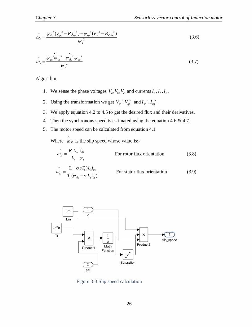
Where ^
sl is the slip speed whose value is:-
^
qsr msl
r r
iR L
L
For rotor flux orientation (3.8)
^ (1 )
( )
r s qs
sl
r ds s ds
sT L i
T L i
For stator flux orientation (3.9)
Figure 3-3 Slip speed calculation
Chapter 3 Sensorless vector control of Induction motor
27
This method of speed estimation is one of the simplest method to execute and it also run into
some disadvantages. When speed is of less values (e.g. frequency is less) the voltage values
,s s
ds qsV V are quite less so then the integration of flux signal derivatives give offset and do not
provide desired accurate estimation. Furthermore, at very high speed of the machine (high
frequency) slip is very less. So speed estimation depends on the parameter like ,r rR L . So these
values should be accurate otherwise it leads to inaccurate estimation.
3.2.2 Direct synthesis of speed from state equations
The observed stator currents and voltages are thereby used to estimate/measure flux linkages
components which are used to find out the speed. The mathematical expression for the rotor
speed by the equation^ ^ ^
slr e . The corresponding equation for this speed estimation
technique are:
( )s
s sr rdr ds s s ds
m m
L LV R L s i
L L
(3.10)
( )s
s sr rdr ds s s ds
m m
L LV R L s i
L L
(3.11)
These mentioned equations are state equations. These are used to estimate rotor flux
components s
dr ands
qr from sensed voltages and currents. Now the current model is used and
is written as:
1
s
s s smdr dr ds r qr
r r
Li
T T
(3.12)
1
s
s s smqr qr r dr qs
r r
Li
T T
(3.13)
Using these relations, we find out the synchronous speed as:
2
s s s s
qr dr dr qr
e
r
(3.14)

Chapter 3 Sensorless vector control of Induction motor
28
The above equations are used to calculate the speed which is finally given as
^ ^
2
s s s s
dr qs qr dsmer
r
i iL
Tr
(3.15)
Where ^
2
s s s s
dr qs qr dsmsl
r
i iL
Tr
(3.16)
Figure 3-4 Slip speed estimation scheme
This speed estimation scheme follows the same set of steps as mentioned earlier. As evident
the hypothesis is highly sensitive to machine parameters that’s it tends to provide poor and low
accuracy of estimation.
3.2.3 Model Reference Adaptive Systems estimator
The open loop estimator accuracy which is derived from state equations depends strongly on
machine parameters. By using closed loop estimator’s accuracy can be increased to a good
amount by using closed loop estimators. Speed estimator which is based on MRAS is studied
in [15]. In this method a comparison in general is usually made among the two estimators
output. As a reference model for the induction machine that estimator is chosen which don’t
contain the quantity to be measured. The other one is referred as adjustable model as this
contains the estimated quantity. The input to the adaptation mechanism depends on input from
obtained error after comparison between the estimators. In sensorless algorithm control the
Chapter 3 Sensorless vector control of Induction motor
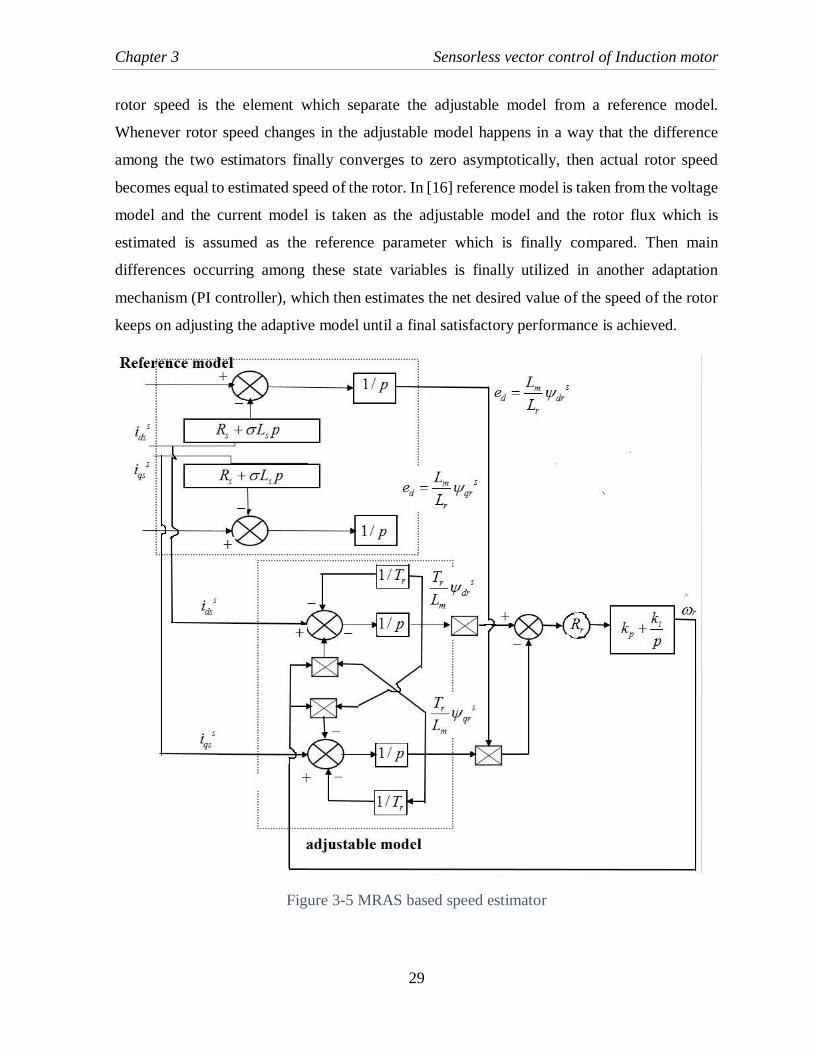
29
rotor speed is the element which separate the adjustable model from a reference model.
Whenever rotor speed changes in the adjustable model happens in a way that the difference
among the two estimators finally converges to zero asymptotically, then actual rotor speed
becomes equal to estimated speed of the rotor. In [16] reference model is taken from the voltage
model and the current model is taken as the adjustable model and the rotor flux which is
estimated is assumed as the reference parameter which is finally compared. Then main
differences occurring among these state variables is finally utilized in another adaptation
mechanism (PI controller), which then estimates the net desired value of the speed of the rotor
keeps on adjusting the adaptive model until a final satisfactory performance is achieved.
Figure 3-5 MRAS based speed estimator
Chapter 3 Sensorless vector control of Induction motor
30
Reference model makes the use of measured stator voltage and current to finally find out the
rotor flux as described:
1
( )s s s srdr ds s ds s ds
m
L dV R i L i
L s dt (3.17)
1
( )s s s srqr qs s qs s qs
m
L dV R i L i
L s dt (3.18)
The adjustable model calculates/measures the same amount of flux using the estimated speed
and the measured current as depicted:
1
( )s
s s sm drdr ds r qr
r r
Li
s T T
(3.19)
1
( )
s
qrs s smqr qs r dr
r r
Li
s T T
(3.20)
In [17] similar type of speed estimators has been taken which is dependent on MRAS and then
a secondary variable has been taken as a reference quantity through passage of the rotor flux
through a first order delay instead of a pure integration for nullifying the offset. Still as it can
be seen that their proposed algorithm produces estimated speed which is inaccurate whenever
the excitation frequency is kept underneath a certain level. Apart from these algorithms also
undergoes from the uncertainties in parameters of the because of the reference model because
parameter variation in the reference can’t be modified or corrected. Although [18] suggests an
alternative technique of MRAS which is mainly based upon the electromotive force instead of
the rotor flux which is considered as reference quantity for estimation of speed and in this
method problem of the integration has been successfully overcome to good extent. Further in
this a new variable is proposed which basically signifies the instantaneous reactive power for
optimizing the magnetizing current. So in this MRAS algorithm the role of stator resistance
eventually disappears from major of the equations making the algorithm robust to that particular
parameter.

Chapter 3 Sensorless vector control of Induction motor
31
3.2.4 Adaptive Observer
Any state observer is basically a model based state estimator which could be utilized for the
state estimation of a non-linear dynamic system. The states are first predicted through the
calculations with use of a mathematical model, but these state which are predicted undergoes
continuous correction by using a feedback correction scheme. The Stator and rotor equations
of the induction machine which are expressed in stator coordinates which are used to obtain a
full order speed observer. A full order observer uses the machine electrical model ins sd q
frame, where the state variables are stator currents are s
dsi and s
qsi and the rotor fluxes are s
dr
and s
qr .
The Rotor voltage equations can be written as:
1
s
s s smdr dr r qr ds
r r
Li
T T
(3.21)
1
s
s s smqr qr r dr qs
r r
Li
T T
(3.22)
Equating (4.10) with (4.20) we can get
2 2
2 2
( ) 1s
s s s sds r m s r r m r mds dr qr ds
s r s r s r s
di R L R L R L Li v
dt L L L L L L L
(3.23)
2 2
2 2
( ) 1s
qs s s s sr m s r r m r mqs dr qr qs
s r s r s r s
di R L R L R L Li v
dt L L L L L L L
(3.24)
Thus these equations constitute the desired equation which can be written in the form of any
general stare equation as
d
X AX BUdt

Chapter 3 Sensorless vector control of Induction motor
32
Where
s
ds
s
qs
s
ds
s
qs
i
iX
0
0
s
ds
s
qs
v
vU
s
ds
s
qs
iY
i
. 1 0 0 0
0 1 0 0C
And
2 2
2 2
2 2
2 2
( )0
( )0
0
0
r m s r m r m r
s r s r s r
r m s r m rr r
s r s r s r
m r rr
r r
m r rr
r r
R L R L L L L
L L L L L L
R L R L L LL
L L L L L LA
L R R
L L
L R R
L L
10
10
0 0
0 0
s
s
L
BL
Thus the input voltage signals are measured from the machine terminal. Now if speed parameter
in A matrix is known we can find out the fluxes and the current from the state equations.
However, if speed is not correct then there is bound to be deviations between the actual and the
estimated value. Thus in the end estimated currents are compared with the actual machine
terminal currents and error is injected into the speed estimating algorithms so that this error
vanishes.
The speed algorithm used for the speed estimation in this technique is
^ ^ ^ ^ ^
( ) ( )r p i s r i s r i i s r i s rk e e k e e dt (3.25)
3.3 Conclusion
In this chapter different Sensorless speed estimation techniques have been described along with
their speed estimation ways which has also been described in brief. These techniques utilize the
sensed voltage and current values and thus with this the speed is estimated. The experimental
verification of these equations have been shown in chap 4 thus establishing the advantages of
drive operations without speed sensors.

33
CHAPTER 4
4 SIMULATIONS AND RESULTS
4.1 Introduction
The three phase induction motor with suitable rating has been simulated by using
Matlab/Simulink model for its speed estimation. The speed tracking performance has been
shown with vector control which first includes the use of speed sensor and then without it as
required in the sensorless control schemes. A number of speed estimation techniques have been
taken into consideration and their performance is verified by simulation results along with its
torque variation waveforms. The specification of the IM used for sensorless estimation schemes
is 50 HP, 4 pole, 3-phase with parameters: Rs = 0.087 ohm, Rr= 0.228 ohm, Ls= Lr = 0.0355
H, Lm= 0.0347 H, J= 1.662 Kg.m2, B= 0.1 Nm.sec
4.2 Vector Control Simulation Results
Different operating conditions were investigated in order to validate the direct vector control
model and to demonstrate the effectiveness of the system modelling and simulation. The speed
waveform of the direct vector control shows the reference and actual motor speeds at t =0.5 sec,
motor speed is raised from 0 to 70 rad/sec then at t =1 sec it is further decreased to 120 rad/s in
reverse direction and so on varied with time to check the effectiveness of the system.
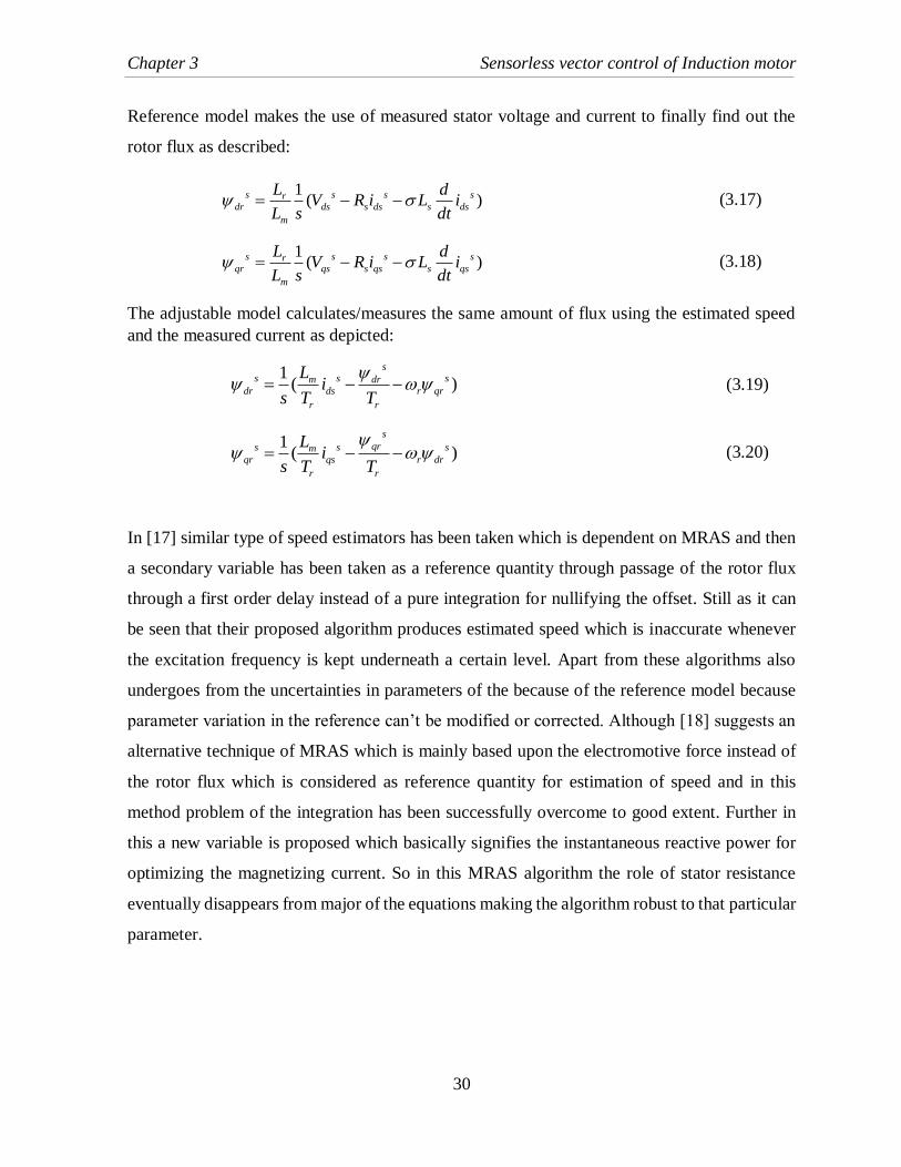
The speed dip at t=6s is due to load torque augmentation. Electromagnetic torque response is
also illustrated. Load torque is increased at t=1s. Despite the presence of torque pulsations, the
motor follows precisely the load torque value. At t=4s, motor speed is reduced from 60 to -120
rad/s. We notice in both figures that in presence of disturbance the vector control responds
adequately and brings back the controlled variable to its desired value. The other two speed
control methods are the indirect control method and the stator oriented control methods and
these are simulated for same set of reference speed as the direct oriented control. The speed
response gets better in indirect control as compared to the direct one although the ripples in
speed response are there but are of low magnitudes and thus overall system gives a good

Chapter 4 Simulations and Results
34
performance. The stator oriented control in comparison shows more ripples and speed response
is little less good than the indirect method still the response is very much fine.
4.2.1 Direct Vector Control
Figure 4-1 Speed Response of Direct Vector Control
Figure 4-2 Torque Response of Direct Vector Control

Chapter 4 Simulations and Results
35
Figure 4-3 Waveform of stator current ,I I
Figure 4-4 Waveform of Stator current , , ca bI I I
4.2.2 Indirect Vector Control
Figure 4-5 Speed Response of Indirect Vector Control

Chapter 4 Simulations and Results
36
4.2.3 Stator Oriented Control
Figure 4-7 Waveform of Stator Currents ,I I
4.3 Sensorless Vector Control Simulation Results
4.3.1 Estimation of synchronous and slip speed
Figure 4-8 Speed Response of sensorless slip estimator scheme
Figure 4-6 Speed Response of Stator Oriented Vector Control
Chapter 4 Simulations and Results
37
Figure 4-10 Waveform of Stator Currents ,I I
Figure 4-11 Waveform of Stator Currents , , ca bI I I
Figure 4-9 Torque response of sensorless speed estimator scheme

Chapter 4 Simulations and Results
38
4.3.2 Direct synthesis of speed from state equations
Figure 4-12 Speed response of open loop estimator scheme
Figure 4-13 Torque response of open loop estimator scheme
Chapter 4 Simulations and Results
39
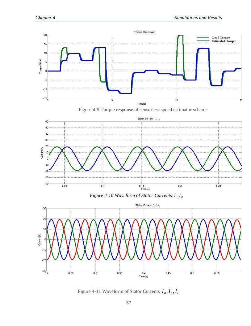
Figure 4-14 Waveform of Stator Current ,I I
Figure 4-15 Waveform of Stator Current , , ca bI I I
4.3.3 MRAS Estimator
Figure 4-16 Speed response of MRAS

Chapter 4 Simulations and Results
40
Figure 4-17 Torque response of MRAS
Figure 4-18 Waveform of Stator Current ,I I
Figure 4-19 Waveform of Stator Current , , ca bI I I
Chapter 4 Simulations and Results
41
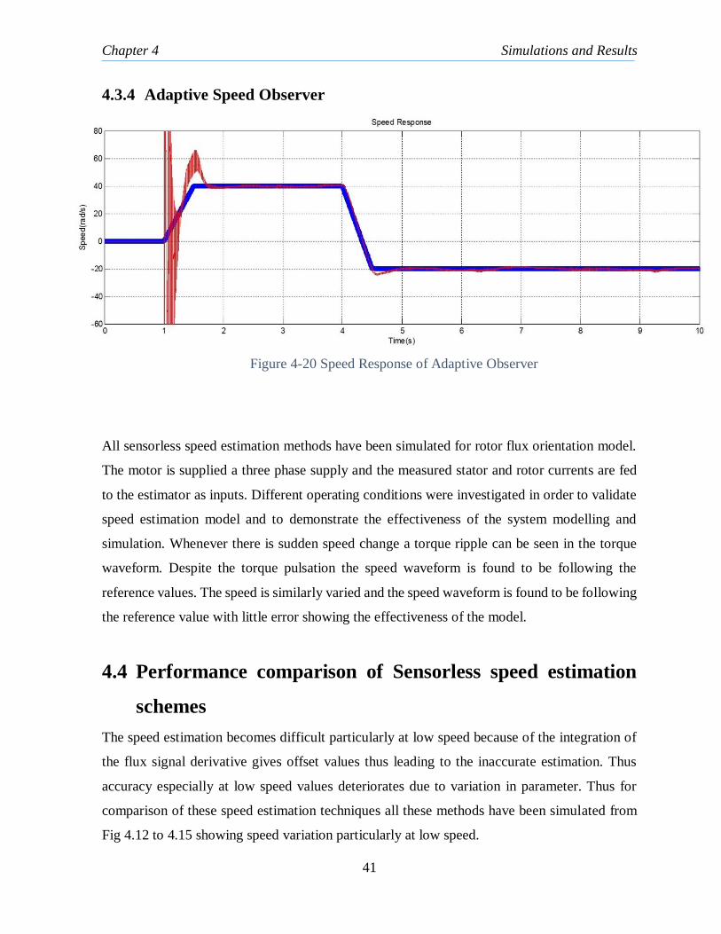
4.3.4 Adaptive Speed Observer
All sensorless speed estimation methods have been simulated for rotor flux orientation model.
The motor is supplied a three phase supply and the measured stator and rotor currents are fed
to the estimator as inputs. Different operating conditions were investigated in order to validate
speed estimation model and to demonstrate the effectiveness of the system modelling and
simulation. Whenever there is sudden speed change a torque ripple can be seen in the torque
waveform. Despite the torque pulsation the speed waveform is found to be following the
reference values. The speed is similarly varied and the speed waveform is found to be following
the reference value with little error showing the effectiveness of the model.
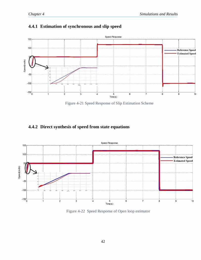
4.4 Performance comparison of Sensorless speed estimation
schemes
The speed estimation becomes difficult particularly at low speed because of the integration of
the flux signal derivative gives offset values thus leading to the inaccurate estimation. Thus
accuracy especially at low speed values deteriorates due to variation in parameter. Thus for
comparison of these speed estimation techniques all these methods have been simulated from
Fig 4.12 to 4.15 showing speed variation particularly at low speed.
Figure 4-20 Speed Response of Adaptive Observer
Chapter 4 Simulations and Results
42
4.4.1 Estimation of synchronous and slip speed
4.4.2 Direct synthesis of speed from state equations
Figure 4-21 Speed Response of Slip Estimation Scheme
Figure 4-22 Speed Response of Open loop estimator

Chapter 4 Simulations and Results
43
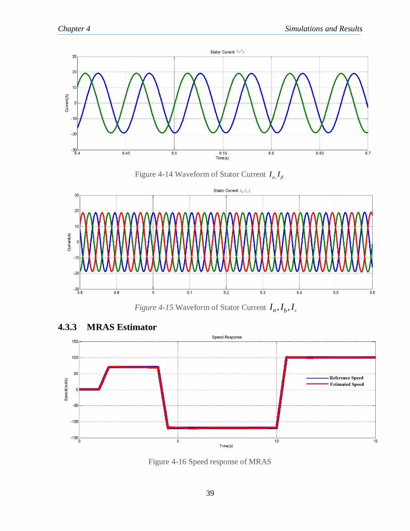
4.4.3 MRAS Estimator
4.4.4 Adaptive Speed Observer
4.5 Conclusion
In this chapter vector control techniques which uses sensors namely direct, indirect and stator
oriented control have been simulated to show the improved performance of the vector control
of the induction machine in comparison to the scalar method. The obtained results have been
perfect showing the efficiency of this techniques. Thereafter different sensorless speed
estimation techniques have been simulated and for their performance comparison at low speed
and steady state they have been simulated and compared accordingly.
Figure 4-23 Speed Response of MRAS scheme
Figure 4-24 Speed Response of Adaptive speed Observer

44
CHAPTER 5
5 CONCLUSION AND FUTURE SCOPE
5.1 Conclusion
In this dissertation the main focus has been on finding out the best speed estimation
techniques for the sensorless operation of the induction motor. The majority of techniques of
speed extraction rely on the induction machine which can also lead to inaccuracies in speed
estimation. First mathematical System modelling and various simulations have been shown
using Matlab/Simulink. As described rotor flux can be found out by means of rotor flux
observer where they are obtained by utilizing voltage and current equations of the IM in
stationary reference frame. Similarly, with the help of voltage and current sensors speed is
estimated for various sensorless schemes. For high performance drives different flux and
speed estimation techniques can be used.
Among there presented schemes MRAS scheme shows best behavior at steady state operation
as demonstrated in section 4.4. It can be seen it provides a very good response. The response
is as good as direct vector control thus showing its effectiveness. The simulations show there
is room for improvement in performance of the system particularly for low speed range.
During regular change in loading system stability could be improved to achieve better vector
control performance.
5.2 Scope for future work
In this thesis the simulation work shows a great promise for the studied methods. Different
estimator’s dynamic response and the estimation accuracy can be further improved by re-
tuning and also with the help of online parameter estimation techniques will facilitate
observation of change of motor parameters during operation especially at low speed. Several
other methods can also be applied like Extended Kalman Filter (EKF), neural network based
estimators and sliding mode estimators.

45
6 References
[1] F. Blaschke, “A new method for the structural decoupling of A.C. induction machines,” in Conf. Rec.
IFAC, Duesseldorf, Germany, Oct. 1971, pp. 1–15.
[2] A. Abbondanti, M. B. Brennen, “Variable speed induction motor drives use electronic slip
calculator based on motor voltages and currents,” IEEE Trans. Industrial Applications, vol.11,
1975, pp. 483-488.
[3] B. K. Bose, Modern Power Electronics and AC Drives, Prentice-Hall, New Delhi, 2002.
[4]. W. L. Erdman and R. G. Hoft, “Induction machine field orientation along air gap and
stator flux,” IEEE Trans. On Energy Conversion, vol. 5, no. 1, pp.115-121, Mar 1990.
[5] S. Xepapas, A. Kaletsanos, F. Xepapas, S. Manias, “Sliding-mode observer for speed sensorless
induction motor drives,” IEE Proc.-Control Theory Application, vol. 150, no. 6, November 2003,
pp.788-795.
[6]. Ahmad Razani Haron, Nik Rumzi Nik Idris,“Simulation of MRAS-based Speed Sensorless
Estimation of Induction Motor Drives” Power and Energy Conference, PECon '06. IEEE
International, page 411-415 November 28-29, 2006.
[7] M. Ishida, K. Hayashi, M. Ueda, “A speed detection method of squirrel cage induction motor
utilizing rotor slot-harmonics in the air gap and its application to slip frequency control,”
Electrical Engineering, Japan, vol. 99, no. 3, 1979, pp. 74-84.
[8] J. Moreira, K. Hung and T. Lipo, “A simple and robust adaptive controller for the tuning
correction in field-oriented induction machines,” IEEE Trans. Ind. Applicat., vol. 28, pp.
1359-1366, Nov./Dec. 1992.
[9] P.L.Jansen and R.D.Lorenz “Transducerless position and velocity estimation in induction
and salient ac machines”, IEEE Tran. IA, vol. 31, no.2, pp.240-247, Mar/April, 1995
[10] B.Robyns, B.Frederique, “A methodology to determine gains of induction motor flux
observers based on a theoretical parameter sensitivity analysis”, IEEE Trans. PE, vol. 15,
no.6, pp.983-995, 2000
46
[11] Takahashi and T. Noguchi, “A new quick-response and high-efficiency control strategy of
an induction motor,” IEEE Trans. Ind. Applicat., vol. 22, pp.820- 827, Sep./Oct. 1986.
[12] P. L. Jansen, C. O. Thompson, and R. D. Lorenz, “Observer based direct field orientation
for both zero and very high speed operation,” in Proc. PCC, Yokohama, Japan, Apr. 1993,
pp.432-437.
[13] K Minami, M. Vélez-Reyes, D. Elten, G. C. Verghese and D. Filbert, “Multistage speed
and parameter estimation for induction machines,” IEEE Power Electronics Specialist’s
Conference, Boston MA, Jun. 1991.
[14] I. J. Ha and S. H. Lee, “An on-line identification method for both stator and rotor
resistances of induction motors without rotational transducers,” ISIE’96, Warsaw, Poland,
Jun. 1996.
[15] C.Schauder “Adaptive Speed Identification for Vector Control of Induction Motor without
Rotational Transducers” IEEE Tran. IA vol. 28, no. 5, pp. 1054-1061, Oct.1992
[16] H.Tajima, Y.Hori “Speed Sensorless Field Orientation Control of the Induction Machine”
IEEE Tran. IA vol. 29, no. 1, pp. 175-180, Feb.1993
[17] C.Schauder “Adaptive Speed Identification for Vector Control of Induction Motor without
Rotational Transducers” IEEE Tran. IA vol. 28, no. 5, pp. 1054-1061, Oct.1992
[18] F.Z.Peng, T.Fukao “Robust Speed Identification for Speed Sensorless Vector Control of
Induction Motors” IEEE Tran. IA vol. 30, no. 5, pp.1234-1239, Oct.1994
[19] I. Boldea and S. A. Nasar, “Vector Control of AC Drives”, CRC Press, 1992.
[20] Radu Bojoi, Paolo Guglielmi and Gian-Mario Pellegrino,“Sensorless direct field-oriented
control of three-phase induction motor drives for low-cost applications,” IEEE Trans. Ind.
Appl., vol. 44, no. 2, pp. 475-481, Mar. 2008.
[21]Jaison Cherian and Johnson Mathew,” Parameter Independent Sensorless Vector Control
of Induction Motor” IEEE International Conference on Power Electronics, Drives and
Energy Systems December16-19, 2012, Bengaluru, India
[22] Ahmed A.Z. Diab,” Implementation of Full Order Observer for Speed
Sensorless Vector Control of Induction Motor Drive ” 15th International conference on
micro/nanotechnologies and electron decices EDM
47
[23]Renukrishna B. and Shanifa Beevi,” Sensorless Vector Control of Induction Motor Drives
using Rotor Flux Observer” IEEE International Conference on Power Electronics, Drives
and Energy Systems December16-19, 2012, Bengaluru, India
[24] Djordje Stoji´c, Milan Milinkovi´c, Slavko Veinovi´c,” Improved Stator Flux Estimator
for Speed Sensorless Induction Motor Drives” IEEE Transactions on power electronics ,
Vol. 30, No. 4, April 2015
7 APPENDIX FOC & Open loop simulation of IM:
Power Rating: 3 HP
Stator Voltage: 460 volt
Frequency: 50 Hz
Number of Poles: 4
Stator Resistance: 0.6837 ohm/phase
Stator leakage Inductance: 0.004152 H/phase
Rotor Resistance: 0.451 ohm/phase
Rotor leakage Inductance: 0.004152 H/phase
Mutual Inductance: 0.1486 H
Inertia: 0.05 kg m2
Sensorless Vector Control:
Power Rating: 50 HP
Stator Voltage: 460 volt
Frequency: 60 Hz
Number of Poles: 4
Stator Resistance: 0.087 ohm/phase
Stator leakage Inductance: 0.0355 H/phase
Rotor Resistance: 0.228 ohm/phase
Rotor leakage Inductance: 0.0355/phase
Mutual Inductance: 0.0347 H
Inertia: 1.662 kg m2