performance improvement of a diesel generating set … improvement of a diesel generating set with...
TRANSCRIPT
Performance Improvement of a Diesel GeneratingSet with Fuzzy Control for Stand-alone and
Grid-connected OperationsGiann B. Reis, Rodolpho V. A. Neves, Cassius R. Aguiar, Renan F. Bastos, Ricardo Q. Machado,
and Vilma A. Oliveira
Abstract—This paper proposes a management strategy fora diesel generating set (GS) covering the mechanical part ofthe system which includes speed and active power control,the electrical part of the system which includes voltageand reactive power control, and the synchronism with thegrid. The management is based on a fuzzy PD+I controllerstructure which uses a fixed controller surface for all fuzzycontrollers (FCs). Simulations results for both stand-alone andgrid-connected operations using fuzzy controllers were superiorwhen compared to commercial methods (CM).
Index Terms—Coordinated fuzzy control, Distributed gener-ation, Gen-set, GS synchronism.
I. I NTRODUCTION
T HE use of alternative energy sources in distributed gen-eration (DG) systems improves voltage levels, reduces
power losses in co-generation projects [1], and cuts powertransmission costs as the DGs are installed close to the localconsumption [2], [3], [4], [5]. Diesel-driven generators arecommonly used due to their simplicity, wide range of powergeneration and low cost when compared to other alternativesources [2], [6], [7], [8].
One of the major problems caused by connecting a DGsystem to the grid is an alteration of the system-short-circuitparameters, which can lead to uncoordinated operation of thesystem protection and consequent damage to the electricalequipment connected to the DG terminals [9]. Unwantedoscillations in the power bus may also occur, as well asincreasedRI2 andXI2 losses in the impedance lines, causedby the reactive flow current [10]. One way to maintain thequality of the bus voltage within the established standardsis to control the flow of active and reactive power of theconnected DG.
Active power of the diesel GS can be controlled byregulating the torque provided by the diesel engine. On theother hand, reactive power of the GS is controlled by anautomatic voltage regulator (AVR) which regulate the localbus voltage level and allows reactive power flow control [11].
The diesel GS is nonlinear [6], [12], due primarily tothe torque-rotation ratio, actuators and motor valves. Fuzzycontrollers have a good responses when used with nonlinearsystems [13], [14], [15], [16], [17], [18], and have been usedto regulate the grid-connected and stand-alone GS operationmodes [3], [19], [20], [21], [22], [23], [24].
Manuscript received June 26, 2013. This paper was supported byFundacao de Amparoa Pesquisa do Estado de Sao Paulo under grantFAPESP-2011/02170-5.
G. B. Reis is with the Electrical Engineering Department, EngineeringSchool of Sao Carlos, University of Sao Paulo - USP, SP - BRAZIL, e-mail: [email protected].
A fuzzy control approach for both stand-alone and grid-connected operations of the entire GS is proposed. TheGS fuzzy controller designed for stand-alone operation ispresented first, followed by the fuzzy approach for grid-connected operation in which the terminal voltage and reac-tive power controllers are coordinated to reduce the reactivepower exchange with the IEEE Standard 1547 model grid.
II. SYSTEM DESCRIPTION
The plant used in this study was built with PSCADr
software and comprises an IEEE-1547 standard grid, a DGsystem, control loops, transformers and local loads.
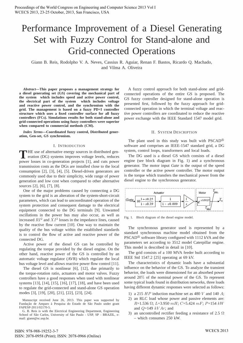
The DG used is a diesel GS which consists of a dieselengine (see block diagram in Fig. 1) and a synchronousgenerator. The motor inputGate is the output of the speedcontroller or the active power controller. The motor outputis the torque which transfers the mechanical power from thediesel engine to the synchronous generator.
Fig. 1. Block diagram of the diesel engine model.
The synchronous generator used is represented by astandard synchronous machine model obtained from thePSCADr software library configured with 1112 kVA and theparameters set according to 3512 model Caterpillar engine.This model is described in detail in [10].
The grid consists of a 100 MVA feeder built according toIEEE Std 1547.2 [25] operating at 69 kV.
The characteristics of dynamic loads have a substantialinfluence on the behavior of the GS. To analyze the transientbehavior, the loads were dimensioned for an absorbed poweraround 20%of the nominal power of the GS. To representsome typical loads found in distribution networks, three loadshaving different dynamic responses were selected as follows:
1) a 215HP induction machine set as 480V and 140A;2) an RLC load whose power and passive elements are:
R=1.536Ω; L=3.950mH; C=5.424mF ; P=154kWandQ=149 kV Ar; and
3) an uncontrolled rectifier feeding a resistance of 2.5Ω– which consumes 250 kW.
Proceedings of the World Congress on Engineering and Computer Science 2013 Vol I WCECS 2013, 23-25 October, 2013, San Francisco, USA
ISBN: 978-988-19252-3-7 ISSN: 2078-0958 (Print); ISSN: 2078-0966 (Online)
WCECS 2013

Fig. 2. GS block diagram showing the variables used by the controllers.
III. C ONTROL STRATEGY
A FC approach was used for each DG’s control loop. Theblock diagram of the diesel GS with terminal voltage, speed,synchronism and power control loops is shown in Fig. 2, withthe signal acquisition points used in the control loops and theblock diagram of the FC in Fig. 3 withR the reference,ythe variable measured,U the output,Ki the integrating gainof the error,Kp andKd the normalizing gains for the inputseP andeD, respectively.
Fig. 3. Fuzzy PD+I controller.
Also, a low pass first order filter was used to eliminatethe noise from the derivative termeD. The FC output gainsKui andKu were adjusted such that the controller outputU
belongs to the universe of discourse of the control variable,i.e., if the controller is for the motor speed theKui andKu
gains should be adjusted such thatU corresponds to a torquebelonging to the interval 0 to 1.1 pu.
The process of fuzzy inference follows a set of rulesdetermined from expert knowledge and is typically basedon the system’s heuristic [19]. The fuzzy controller wasderived from a control surface which represents the requirednonlinearities such that fast actions on disturbances, butmaintaining the damping required to stabilize the system,are taken.
The surface was defined by the membership functions
shown in Fig. 4(a), as well as fuzzy rules and outputfunctions formed by singletons as presented in Fig. 4(b).
(a)
(b)
Fig. 4. Membership functions of inputs and output. In (a), the functions “P”and “N” have bell distributions and “Z” is triangular; in (b), the functions“DM”, “DP”, “NFN”, “AP” and “AM” are singletons.
The use of singletons as output membership functionsmakes simpler the computations and allows the controloutput to be driven to its extreme values, whereas the useof triangular and bell distributions as input membershipfunctions introduces nonlinearities in the control output suchthat fast and efficient responses are obtained [26]. The bellmembership functions give fast responses to correct transi-tory disturbances while the triangular membership functionslimitate the controller action on steady-state error.
The rules of inference comprise linguistic expressions such
Proceedings of the World Congress on Engineering and Computer Science 2013 Vol I WCECS 2013, 23-25 October, 2013, San Francisco, USA
ISBN: 978-988-19252-3-7 ISSN: 2078-0958 (Print); ISSN: 2078-0966 (Online)
WCECS 2013

as “If eP is P and eD is Z then u is AP ” and combineall inputs to provide a particular output. Table 1 shows thecombinations of the two inputs and one output of the fuzzysystem.
TABLE IFUZZY SYSTEM INFERENCE RULES
ePN Z P
N DM DP NFNeD Z DP NFN AP
P NFN AP AM
To implement the controller, the crisp output is obtained bythe center of area defuzzification method [13], which yields
u =
∑N
k=1µ(Vk)Vk∑N
k=1µ(Vk)
(1)
where N is the number of discretization points of theuniverse of discourse for the output,µ is the degree of truthandVk is the crisp value which the fuzzy system returns foreach input set.
The control surface obtained from the fuzzy rules andmembership functions presented in this paper is shown inFig. 5. The surface shows abrupt variations at the borderbetween positive and negative values such that fuzzy outputswith the same feature are provided, i.e., the fuzzy controlleroutput changes faster when the inputs cross zero. The lateralplateaus show that when the inputs have opposite signs, thefuzzy controller output should be zero. In this case, thesystem tends to reach the equilibrium point then no action isneeded. On the other hand, for situations in which both inputsare positive or negative, the fuzzy controller tends to saturateat its maximum or minimum points, and consequently thefuzzy controller should take more drastic actions for thesystem to return to its equilibrium point.
Fig. 5. Fuzzy control surface.
A. Speed and Active Power Control
The command switchS1 shown in Fig. 2 selects the GSoperation mode. When the GS is under stand-alone operationmode, the switchS1 sets the speed control loop as active.Otherwise, the active power control is set as active. Fig. 6shows the speed and active control loops along with thesynchronism loop.
Fig. 6. Control scheme for active power, speed and synchronism.
The fuel valve apertureGate is used to regulate the dieselmotor speed when the DG operates disconnected from thegrid. The signal frequency generated at the synchronousmachine terminals is a function of the motor speed due to thecoupling between the shaft of the generator and the dieselengine [27]. However, when the DG is connected to the grid,the coupling produces the active power delivered to the grid,since in this case the frequency is determined by the grid.
The input of the speed fuzzy controller is the error signalgiven by:
eω = ωref − ω (2)
whereω is the speed measured from the GS shaft andωref
is the speed reference that is constantly adjusted while theGS is disconnected according to
ωref = ω0 +∆ωsync (3)
whereω0 is the rated synchronous speed and∆ωsync is theoutput of the synchronism controller.
The diesel engine accelerates or decelerates to synchronizeand connect the GS to the grid. The synchronism controlleruses the difference betweenθgrid andθgen and produces thedeviation∆ωsync.
The generator voltageVtgen must be synchronized with thereference obtained from the grid to enable the GS connectionto grid.
The synchronism CM is performed by tracking the phasesof the grid and DG voltages to connect the DG system atthe time that the difference between the phases is within apreset tolerance.
However, there are active and reactive power disturbancesduring the DG connection before the synchronism is es-tablished. To reduce these disturbances, a fuzzy controllerphase-locked loop (FC-PLL) shown in Fig. 6 is used. Usinga phase detector, the argumentθ is extracted from the DGand grid voltagesθgen andθgrid, respectively. The input ofthe FC-PLL is the erroreθ between the phase signals fromGS and the grid.
In the proposed FC-PLL, the GS connection occurs notonly when the proportional error termePθ is within a giventolerance, which means0 ≤ ePθ ≤ tol, but also when thederivative error termeDθ is within the given tolerance. Atthe momentePθ andeDθ are within the given tolerance, theswitch S1 is triggered to change the GS operation mode togrid-connected and then the active power control is set asactive. The FC-PLL useseDθ to modify theθgen speed tomatch with theθgrid speed. Therefore, the FC-PLL reduces
Proceedings of the World Congress on Engineering and Computer Science 2013 Vol I WCECS 2013, 23-25 October, 2013, San Francisco, USA
ISBN: 978-988-19252-3-7 ISSN: 2078-0958 (Print); ISSN: 2078-0966 (Online)
WCECS 2013

the differences in phases and frequencies between the GS andgrid voltages and allows the error to reach the establishedtolerance which minimizes the transient disturbances at theconnection time.
The output of the FC-PLL yields the signal∆ωsync whichfeeds the speed control loop of the GS and is responsibleto change the speed referenceωref (Fig. 6). The referencespeed is thus dependent on the∆ωsync and consequentlyaccelerates or decelerates the generated voltage until it is insynchronism with the grid voltage.
The instant that the DG is connected to the grid thespeed control loop is switched off byS1. The active powercontroller is then activated and takes over the operation ofthe diesel engine to follow the active power referencePref .The active power used to control the power supplied to thegrid is given by power average calculated by:
Pgen =1
T
T∫
0
p dt. (4)
B. Coordinated Control of the Terminal Voltage and ReactivePower
The approach presented for voltage and reactive powerregulation differs from the AVRs available on the market, asit uses two fuzzy loops in parallel to control the voltage andreactive power supplied by the generator.
Reactive power and voltage amplitude are regulated by thesynchronous generator field voltage (Ef ). Unlike existingcommercial systems loops where the voltage and reactivepower control operate independently in the synchronous gen-erator, the proposed approach uses two interconnected fuzzycontrol loops whose responses work together to regulate thegenerator exciter, as illustrated in Fig. 7. In Fig. 7, the upperloop regulates the terminal voltage to followVtref set to1 p.u. The lower loop regulates the reactive power accordingto the set pointQload, the reactive power average measuredfrom the local load. Therefore, the set point was adjustedto supply the local load and the reference value changesaccordingly to the reactive power demanded by the load, i.e.,if there is no reactive power load,Qload is set to 0 kVAr.
Fig. 7. Configuration of the coordinated fuzzy PD+I controller for terminalvoltage and reactive power.
Therefore, the GS supplies only the reactive power neededfor these loads, and cancels the reactive power exchangebetween the DG and the grid, which favors the maintenance
of the unity power factor at the point of the DG connection.The average reactive power can be calculated by:
Qgen =1
T
T∫
0
q dt (5)
with q the instantaneous reactive power.The excitation voltage fieldEf is obtained by adding the
three terms:
Ef = Ef0 +∆EfVt+∆EfQ (6)
with Ef0 the initial condition of the field,∆EfVtthe term
given by the voltage controller and∆EfQ the term given bythe reactive power controller. The term∆EfQ is given by:
∆EfQ = α ∆EQ (7)
whereα is a weighting factor given by:
α = 1− |eVt| (8)
which has maximum value wheneVtis zero. This strategy
thus ensures effective reactive power control as the errorvoltage decreases by prioritizing the terminal voltage control,and it also avoids large oscillations in the voltage levelsupplied to the load, which improves the GS power quality.
IV. SIMULATION RESULTS
The stand-alone operation mode test was performed withconnection and disconnection of loads. The simulation ofthe grid-connected operation mode was performed afterthe connection of the GS to the grid using the FC-PLL.Moreover, the simulation considered active power injectioninto the grid by the DG system. Results using existing CMand controllers are presented for comparison purposes.
Fig. 8(a) demonstrates that when the synchronism CM isused with a phase error tolerance of0.5, large variations inP andQ, of 250 kW and 90 kVAr, respectively, are observed,what represent22.5% and 8.1% of the GS nominal power.However, with the FC-PLL there is a small variation inP .It is also noticed a 8 kVAr peak variation inQ, i.e., 0.7%,of the GS nominal power whereas with the CM the variationin Q is about8.1% as shown in Fig. 8(b).
The loads connection were conducted similarly for eachGS operation mode. First, att = 10 s, a 215 HP three-phase induction motor (IM) was connected (driven by anincreased torque ramp until the torque reached 1 p.u.) andremained connected for 10 s until it was disconnected. AnRLC load was then connected att = 25 s up to 35 s. Finally,a three-phase uncontrolled rectifier was connected to the gridat t = 40 s up tot = 50 s.
The results presented in Fig. 9 show the action of the speedand terminal voltage controllers for the stand-alone operationmode. One simulation used the FC for the speed and voltageterminal, whereas another used a commercial controller forspeed (CCω) from the PSCADr library with the parametersgiven in Table II and a Proportional-Integral controller (PI)set according to [28] to regulate the terminal voltage.
Compared with the proposed FC, the PI associated withthe CCω (CCω+PI) allowed speed variations 2.5 times greaterwhen connecting or disconnecting loads which exceeded the
Proceedings of the World Congress on Engineering and Computer Science 2013 Vol I WCECS 2013, 23-25 October, 2013, San Francisco, USA
ISBN: 978-988-19252-3-7 ISSN: 2078-0958 (Print); ISSN: 2078-0966 (Online)
WCECS 2013

(a)
(b)
Fig. 8. Transients inP andQ caused by the effect of the grid connection.Where (a) is for CM and (b) is for FC-PLL.
limit recommended by IEEE Std 1547.2 [25] as shown inFig. 9 by UsL limit, and also presented responses which weretwice slower. Results for the terminal voltage were similarfor both controllers.
0 5 10 15 20 25 30 35 40 45 50 550.96
0.98
1
1.02
IM RLC Load RectifierVt (
pu)
0 5 10 15 20 25 30 35 40 45 50 550.99
1
1.01
ω (
pu) IM RLC Load Rectifier
Time (s)
CCω+PI FC UsL
Fig. 9. GS terminal voltage and speed obtained with the FC and CCω+PIcontrollers with the recommended UsL for the stand-alone operation mode.
The load tests for grid-connected operation mode followedthe same steps previously described for evaluating the con-trollers with the GS disconnected. Figs. 10 and 11 compare,respectively, the results obtained for theP andQ powers bythe FC developed with those from the GS controlled by aPI for the exciter set according to IEEE Std 421 [29], and acommercial controller for active power control (CCP ) withparameters given in Table II. Results are obtained for powertransference and load connections using the association ofthe CCP and PI (CCP + PI) and the proposed FC.
TABLE IICOMMERCIAL CONTROLLERS
SpeedCCω(s) Active powerCCP (s)0.0625s+0.25
0.0002s2+0.001s+10.00125s+0.005
0.0002s2+0.001s+1
0 5 10 15 20 25 30 35 40 45 50 55−400
−200
0
200
400
IM RLC Load Rectifier
PC
CP+
PI (
kW)
DG Grid Load
0 5 10 15 20 25 30 35 40 45 50 55−400
−200
0
200
400
PF
C (
kW)
IM RLC Load Rectifier
Time (s)
Fig. 10. Active power generated and absorbed by the elements thatcomprise the system.
0 5 10 15 20 25 30 35 40 45 50 55
−200
0
200
QC
CP+
PI (
kVA
r)
IM RLC Load Rectifier
DG Grid Load
0 5 10 15 20 25 30 35 40 45 50 55
−200
0
200
QF
C (
kVA
r)IM RLC Load Rectifier
Time (s)
Fig. 11. Reactive power generated and absorbed by the elementsthatcomprise the system.
TheP andQ power responses are positive when the sourceprovides energy, otherwise it consumes energy. Variations inQ were ten times smaller at the connection time of the GSto the grid and responses twice faster to stabilizeQ at theconnection of loads using the proposed FC when comparedto the commercial controllers.
The terminal voltage response was also faster with the FCthan with the PI as shown in Fig. 12.
10 15 20 25 30 35 40 45 50 550.995
1
1.005
1.01
Vt (
pu)
IM RLC Load Rectifier
10 15 20 25 30 35 40 45 50 55
0.96
0.98
1
IM RLC Load Rectifier
Time (s)
PF
CCP+PI FC
Fig. 12. Comparison of the terminal voltage and power factor fortheCCP + PI and FC.
The root mean square errors of the power factor deviationfrom the unity were 1.695% for the association CCP +PI and1.228% for the proposed FC, demonstrating that the FC wasfaster in correcting the terminal voltage.
V. CONCLUSION
The management proposed was efficient to control thediesel engine and the synchronous machine and also thesynchronism with the grid. The proposed controllers also
Proceedings of the World Congress on Engineering and Computer Science 2013 Vol I WCECS 2013, 23-25 October, 2013, San Francisco, USA
ISBN: 978-988-19252-3-7 ISSN: 2078-0958 (Print); ISSN: 2078-0966 (Online)
WCECS 2013
allowed fast and accurate actions, leading to smaller oscilla-tions of the controlled variables in relation to a commercialcontroller.
The FC coordinated structure developed was able to reg-ulate the reactive power generated to increase the powerfactor at the point of connection to the distribution grid,while maintaining the level of the terminal voltage withinthe limits recommended by IEEE Std 1547.2 [25]. Thus, thecoordinated FC with reactive power control showed to beefficient to supply the local loads with the reactive powercoming from the GS and avoiding reactive power exchangeswith the grid.
The FC-PLL reduced the transient caused by the con-nection to the grid as recommended by IEEE Std 1547.2[25], which avoided the propagation of the active powertransfer disturbance to the grid. With the synchronism CMthe disturbance was significant, extending over the entireperiod of power transfer increasing.
Although the synchronism CM provides a faster connec-tion between the sources, it allows large disturbances inP and Q since there is only phase control. However, theFC-PLL was able to reduce the phase difference and alsoadjusted the speed which the phase difference was reduced.
The grid-connected FC enabled a power factor closer tounity for the different simulation scenarios, whereas thecommercial controllers showed a similar PF andVt responsesonly for the IM connection which absorbs power slowly.
REFERENCES
[1] W. Elkhattam and M. Salama, “Distributed generation technologies,definitions and benefits,”Electric Power Systems Research, vol. 71,no. 2, pp. 119–128, Oct. 2004.
[2] M. Rashed, A. Elmitwally, and S. Kaddah, “New control approachfor a pv-diesel autonomous power system,”Electric Power SystemsResearch, vol. 78, no. 6, pp. 949–956, Jun. 2008.
[3] N. Sisworahardjo, M. El-Sharkh, and M. Alam, “Neural networkcontroller for microturbine power plants,”Electric Power SystemsResearch, vol. 78, no. 8, pp. 1378–1384, Aug. 2008.
[4] A. Amr, S. Rady, and E. Badreddin, “A plant for cogeneration ofelectricity and water powered by renewable energy sources based onusing high level of automation,” inProc. 10th International Conferenceon Intelligent Systems Design and Applications (ISDA), 2010, Cairo,Dec. 2010, pp. 209–213.
[5] P. Ray, S. Mohanty, and N. Kishor, “Dynamic modeling and controlof renewable energy based hybrid system for large band wind speedvariation,” in Proc. IEEE PES Innovative Smart Grid TechnologiesConference Europe (ISGT Europe), 2010, Gothenburg, Oct. 2010, pp.1–6.
[6] A. Cooper, D. Morrow, and K. Chambers, “Development of a dieselgenerating set model for large voltage and frequency transients,”in Proc. IEEE Power and Energy Society General Meeting, 2010,Minneapolis, Jul. 2010, pp. 1–7.
[7] K. Pandiaraj, B. Fox, D. Morrow, S. Persaud, and J. Martin, “Cen-tralised control of diesel gen-sets for peak shaving and system sup-port,” IEE Proceedings - Generation, Transmission and Distribution,vol. 149, no. 2, pp. 126–132, Mar. 2002.
[8] M. Kanoglu, S. K. Isik, and A. Abusoglu, “Performance characteristicsof a diesel engine power plant,”Energy Conversion and Management,vol. 46, no. 11–12, pp. 1692–1702, 2005.
[9] S. Chaitusaney and A. Yokoyama, “Impact of protection coordinationon sizes of several distributed generation sources,” inProc. The 7thInternational Power Engineering Conference, 2005. IPEC 2005, vol. 2,Singapore, Dec. 2005, pp. 669–674.
[10] P. Kundur,Power System Stability and Control. New York: McGraw-Hill, 1994.
[11] S. Vachirasricirikul, I. Ngamroo, and S. Kaitwanidvilai, “CoordinatedSVC and AVR for robust voltage control in a hybrid wind-dieselsystem,” Energy Conversion and Management, vol. 51, no. 12, pp.2383–2393, 2010.
[12] A. Cooper, D. Morrow, and K. Chambers, “A turbocharged dieselgenerator set model,” inProc. 44th International Universities PowerEngineering Conference (UPEC), 2009, Glasgow, Sep. 2009, pp. 1–5.
[13] W. Chen, L. Jiao, R. Li, and J. Li, “Adaptive backstepping fuzzy con-trol for nonlinearly parameterized systems with periodic disturbances,”IEEE Transactions on Fuzzy Systems, vol. 18, no. 4, pp. 674–685, Aug.2010.
[14] H. Lee, “Robust adaptive fuzzy control by backstepping for a classof mimo nonlinear systems,”IEEE Transactions on Fuzzy Systems,vol. 19, no. 2, pp. 265–275, Apr. 2011.
[15] S. Islam and P. Liu, “Robust adaptive fuzzy output feedback controlsystem for robot manipulators,”IEEE/ASME Transactions on Mecha-tronics, vol. 16, no. 2, pp. 288–296, Apr. 2011.
[16] K. Tanaka, M. Tanaka, H. Ohtake, and H. Wang, “Shared nonlinearcontrol in wireless-based remote stabilization: A theoretical approach,”IEEE/ASME Transactions on Mechatronics, vol. 17, no. 3, pp. 443–453, Jun. 2012.
[17] T. Tong and Y. Li, “Adaptive fuzzy output feedback tracking back-stepping control of strict-feedback nonlinear systems with unknowndead zones,”IEEE Transactions on Fuzzy Systems, vol. 20, no. 1, pp.168–180, Feb. 2012.
[18] H. Wu, J. Wang, and H. Li, “Exponential stabilization for a classof nonlinear parabolic pde systems via fuzzy control approach,”IEEETransactions on Fuzzy Systems, vol. 20, no. 2, pp. 318–329, Apr. 2012.
[19] D. McGowan, D. Morrow, and B. Fox, “Multiple input governorcontrol for a diesel generating set,”IEEE Transactions on EnergyConversion, vol. 23, no. 3, pp. 851–859, Sep. 2008.
[20] C. Su, H. Hwung, and G. Lii, “Fuzzy logic based voltage control fora synchronous generator,”Electric Power Systems Research, vol. 41,pp. 225–231, 1997.
[21] R. Liang and Y. Wang, “Fuzzy-based reactive power and voltagecontrol in a distribution system,”IEEE Power Engineering Review,vol. 22, no. 12, pp. 610–618, Dec. 2002.
[22] M. Moutinho, C. da Costa, W. Barra, and J. Barreiros, “Identification,digital control and fuzzy logic techniques applied to a synchronousgenerator,”IEEE Latin America Transactions, vol. 7, no. 2, pp. 141–150, Jun. 2009.
[23] D. Gaonkar and G. Pillai, “Fuzzy logic based coordinated voltageregulation method for distribution system with multiple synchronousgenerators,” inProc. 2010 IEEE PES Transmission and DistributionConference and Exposition, New Delhi, Apr. 2010, pp. 1–5.
[24] A. Soundarrajan and S. Sumathi, “Fuzzy-based intelligent controllerfor power generating systems,”Journal of Vibration and Control,vol. 17, no. 8, pp. 1265–1278, 2011.
[25] IEEE Std 1547.2, “IEEE application guide for IEEE Std 1547, IEEEstandard for interconnecting distributed resources with electric powersystems,” pp. 1–207, Apr. 2009.
[26] J. Jantzen,Foundations of Fuzzy Control. Chichester: John Wiley &Sons, Ltd., 2007.
[27] K. Cheong, P. Li, and J. Xia, “Control oriented modeling and systemidentification of a diesel generator set (genset),” inProc. AmericanControl Conference (ACC), 2010, Baltimore, Jul. 2010, pp. 950–955.
[28] D. Mota and C. Goldemberg, “Comparison between voltage controlstructures of synchronous machines,”IEEE Latin America Transac-tions, vol. 8, no. 6, pp. 631–636, Dec. 2010.
[29] IEEE Std 421.5, “Approved IEEE recommended practice for excitationsystems for power stability studies (superseded by 421.5-2005),” Feb.2005.
Proceedings of the World Congress on Engineering and Computer Science 2013 Vol I WCECS 2013, 23-25 October, 2013, San Francisco, USA
ISBN: 978-988-19252-3-7 ISSN: 2078-0958 (Print); ISSN: 2078-0966 (Online)
WCECS 2013