plan of development for the raven solar energy project
TRANSCRIPT

Plan of Development for the Raven
Solar Energy Project
Prepared for U.S. Bureau of Land Management
Rock Springs Field Office
Prepared by Raven Solar LLC
P.O. Box 900083
Sandy, Utah 84093-0083
Revised January 9, 2020
Plan of Development for the Raven Solar Energy Project
1
Contents Executive Summary ....................................................................................................................................... 7
SECTION 1 ..................................................................................................................................................... 9
PROJECT DESCRIPTION .................................................................................................................................. 9
1.2 Proponents Purpose and Need for the Project ........................................................................... 14
1.2.1 Raven Solar Purpose and Need ........................................................................................... 14
1.2.2 Supplying Electricity ............................................................................................................ 15
1.2.3 Employment ........................................................................................................................ 15
1.2.4 Economic Benefits ............................................................................................................... 15
1.3 Construction Schedule ................................................................................................................ 17
1.4 Authorizations, Permits, Reviews, and Approvals ...................................................................... 18
SECTION 2 ................................................................................................................................................... 19
General Facility Description, Design, and Operation .................................................................................. 19
2.1 Solar Energy Facility Components ............................................................................................... 19
2.1.1 Solar Modules (SM) ............................................................................................................. 19
2.1.2 Solar Tracker and Actuator (Drive) ..................................................................................... 20
2.1.3 Tracking Mounting .............................................................................................................. 21
2.1.4 Steel Posts Anchoring.......................................................................................................... 21
2.1.5 Inverter Units ...................................................................................................................... 22
2.1.6 Electrical Collection System ................................................................................................ 22
2.1.7 Electrical Substation and Switchyard .................................................................................. 22
2.1.8 Battery Energy Storage System ........................................................................................... 23
2.1.9 Access Roads and Connector Roads ................................................................................... 24
2.1.10 Operations and Maintenance Facility ................................................................................. 25
2.1.11 Supervisory Control and Data Acquisition System and Fiber Optic Communications ........ 25
2.1.12 Utilities ................................................................................................................................ 26
2.1.13 Meteorological Sensors ...................................................................................................... 26
2.1.14 Approximate Limits of Disturbance .................................................................................... 27
SECTION 3 ................................................................................................................................................... 28
Project Construction ................................................................................................................................... 28
3.1 Preconstruction Activities ........................................................................................................... 28
3.1.1 Project Component Siting ................................................................................................... 28
3.1.2 Preconstruction Surveys ..................................................................................................... 28

Plan of Development for the Raven Solar Energy Project
2
3.1.3 Flagging Plan ....................................................................................................................... 29
3.1.4 Geotechnical Investigations and Testing ............................................................................ 29
3.1.5 Cone Penetration Testing.................................................................................................... 30
3.1.6 Flat-Plate Dilatometry Testing ............................................................................................ 30
3.1.7 Hollow-Stem Auger Drilling ................................................................................................. 30
3.1.8 Rock Coring/ODEX Drilling .................................................................................................. 31
3.1.9 Test Pit Excavation .............................................................................................................. 31
3.1.10 Non-Invasive Testing ........................................................................................................... 32
3.1.11 Soil Resistivity ...................................................................................................................... 32
3.2 General Construction Information .............................................................................................. 32
3.2.1 Construction Schedule ........................................................................................................ 32
3.2.2 Construction Work Force .................................................................................................... 32
3.2.3 Construction Transportation ............................................................................................... 32
3.2.4 Construction Vehicle Maintenance ..................................................................................... 33
3.2.5 Special Work Areas ............................................................................................................ 33
3.3 General Construction Methods .................................................................................................. 34
3.3.1 Clearing and Grading ........................................................................................................... 34
3.3.2 Topsoil Removal and Protection ......................................................................................... 35
3.4 Solar Energy Facility Construction .............................................................................................. 35
3.4.1 Construction Equipment ..................................................................................................... 35
3.4.2 Material Storage/Staging/Laydown Areas .......................................................................... 36
3.4.3 Solar Energy Facility Construction Refueling ...................................................................... 37
3.4.4 Concrete Batch Plant........................................................................................................... 37
3.4.5 Access Roads and Connector Roads ................................................................................... 37
3.4.6 Solar Arrays ......................................................................................................................... 39
3.4.7 SM Array Work Area and Crane Pad Preparation ............................................................... 39
3.4.8 Solar PV Foundation Types ................................................................................................. 39
3.4.9 Driven Piles, Helical Piles, Earth-screws, and Ballasted Foundations ................................. 40
3.4.10 Electrical Collection System ................................................................................................ 43
3.4.11 Electrical Substation ............................................................................................................ 43
3.4.12 Operations and Maintenance Facility ................................................................................. 44
3.4.13 Meteorological Sensors ...................................................................................................... 44
3.5 Testing and Calibration ............................................................................................................... 44

Plan of Development for the Raven Solar Energy Project
3
3.6 Site Reclamation and Revegetation ............................................................................................ 44
3.7 Health and Safety Program ......................................................................................................... 45
3.7.1 Site Safety and Security....................................................................................................... 45
3.7.2 Emergency Response .......................................................................................................... 45
3.7.3 Fire Safety ........................................................................................................................... 46
3.7.4 Blasting ................................................................................................................................ 46
3.7.5 Transportation Management .............................................................................................. 46
3.7.6 Traffic Management ............................................................................................................ 46
3.7.7 Aviation Lighting ................................................................................................................. 46
3.7.8 Grounding ........................................................................................................................... 47
3.8 Environmental Program .............................................................................................................. 47
3.8.1 Contractor Environmental Plan........................................................................................... 47
3.8.2 Storm Water Control ........................................................................................................... 47
3.8.3 Erosion Control ................................................................................................................... 47
3.8.4 Dust Control ........................................................................................................................ 47
3.8.5 Noxious Weeds Management ............................................................................................. 48
3.8.6 Hazardous Materials and Hazardous Waste Management ................................................ 48
3.8.7 Petroleum Materials and Petroleum Waste Management ................................................ 49
3.8.8 Solid Waste and Sanitary Waste Management .................................................................. 49
3.8.9 Reclamation and Revegetation ........................................................................................... 49
SECTION 4 ................................................................................................................................................... 50
Project Operation and Maintenance .......................................................................................................... 50
4.1 Solar Energy Facility .................................................................................................................... 50
4.1.1 Work Force .......................................................................................................................... 50
4.1.2 Operation and Maintenance Activities ............................................................................... 50
4.1.3 Products Used for Operation and Maintenance ................................................................. 50
4.1.4 Safety .................................................................................................................................. 51
4.1.5 Site Safety and Security.............................................................................................................. 51
4.1.6 Aviation Lighting ................................................................................................................. 51
4.2 Environmental Protection ........................................................................................................... 52
SECTION 5 ................................................................................................................................................... 52
Project Decommissioning ........................................................................................................................... 52
5.1 Solar Energy Facility Decommissioning ....................................................................................... 52
Plan of Development for the Raven Solar Energy Project
4
SECTION 6 ................................................................................................................................................... 53
Environmental Resources ........................................................................................................................... 53
6.1 Wildlife ........................................................................................................................................ 53
6.1.1 Summary of Wildlife Information ....................................................................................... 53
6.1.2 Wildlife Management Plans ................................................................................................ 53
6.1.3 Vegetation and Special-status Plants .................................................................................. 53
6.1.4 Surface Water Features and Wetlands ............................................................................... 54
6.1.5 Visual Resources ................................................................................................................. 54
6.1.6 Cultural Resources .............................................................................................................. 54
6.1.7 Paleontological Resources .................................................................................................. 55
6.1.8 Mitigation Measures and Best Management Practices ...................................................... 55
6.1.9 Operational Monitoring ...................................................................................................... 55
SECTION 7 ................................................................................................................................................... 56
References .................................................................................................................................................. 56
Tables Table 1 Approximate Surface Disturbance ................................................................................................. 10 Table 2 Anticipated Project Construction Schedule .................................................................................. 17 Table 3 Summary of Potential Federal, State, and Local Permit Requirements and Authorizations ........ 18 Table 4 Project Location ............................................................................................................................. 19 Table 5 Disturbance Area ............................................................................................................................ 27 Table 6 Flagging Colors .............................................................................................................................. 29 Table 7 Typical Vehicles and Equipment Used for Solar Energy Facility Construction .............................. 35 Table 8 Dust Suppressants and Environmental Considerations ................................................................. 48
Figures
Figure 1 Conceptual Project Area Overview ............................................................................................... 11 Figure 2 Conceptual Solar Power Generation Area - Project Overview .................................................... 12 Figure 3 Conceptual Project Laydown / Substation Area Detail ................................................................. 13 Figure 4 Typical Solar Module Configuration ............................................................................................. 20 Figure 5 Solar Tracker and Actuator ........................................................................................................... 21 Figure 6 Tracking Mounting ........................................................................................................................ 21 Figure 7 Steel Posts Anchoring.................................................................................................................... 22 Figure 8 Typical Electrical Substation.......................................................................................................... 23 Figure 9 Typical O & M Building .................................................................................................................. 25 Figure 10 SCADA System ............................................................................................................................. 26 Figure 11 Meteorological Sensors .............................................................................................................. 27

Plan of Development for the Raven Solar Energy Project
5
Figure 12 Typical Equipment Delivery Truck (and Offloading) .................................................................. 33 Figure 13 Driven Pile ................................................................................................................................... 40 Figure 14 Helical Pile ................................................................................................................................... 41 Figure 15 Earth Screw Foundation ............................................................................................................. 42 Figure 16 Ballasted Foundation ................................................................................................................. 42 Figure 17 Typical Underground Cable Trench ............................................................................................. 43
Attachments
Attachment A Proposed Solar Module Specifications
Plan of Development for the Raven Solar Energy Project
6
Acronyms and Abbreviations
AC Alternating Current BESS Battery Energy Storage System BLM U.S. Bureau of Land Management BMP Best Management Practice CFR Code of Federal Regulations CPT Cone Penetration Testing DMT Dilatometry Testing DOE U.S. Department of Energy DOI Department of the Interior EIS EMS
Environmental Impact Statement Energy Management system
EO ESS
Executive Order Energy Storage System
FAA Federal Aviation Administration HSA Hollow-Stem Auger KOP Key Observation Point KV KW
Kilovolt Kilowatt
MS Meteorological Sensors mph Miles Per Hour MW Megawatt NEPA National Environmental Policy Act NEPDG NREL
National Energy Policy Development Group National Renewable Energy Laboratory
NRHP National Register of Historic Places O&M Operations and Maintenance PA Programmatic Agreement PCB PCS
Polychlorinated Biphenyl Power Conversion System
POD Plan of Development ROW Right-of-Way SCADA Supervisory Control and Data Acquisition SPCC Spill Prevention Control and Countermeasure SUV Sport Utility Vehicle SWPPP Storm Water Pollution Prevention Plan TBD USACE
To Be Determined U.S. Army Corps of Engineers
USFWS U.S. Fish and Wildlife Service VRM Visual Resource Management WECC Western Electricity Coordinating Council SM Solar module

Plan of Development for the Raven Solar Energy Project
7
Executive Summary Raven Solar, LLC (“Proponent”) is proposing development of the Raven Solar LLC (“project” or “facility”). The project is a utility-scale solar energy generating facility of 66 megawatts (MW) to be located on approximately 400 acres of public land administered by the Bureau of Land Management (BLM). In addition, a 3.9-mile long underground 34.5-kV generation tie power line (gen-tie line) in a 30-foot wide ROW is currently being considered to connect the facility to the Raven substation located to the northwest and will parallel Wyoming Highway 372 (WY 372). The gen-tie line and ROW will be located on 10.3 acres of Wyoming Department of Transportation (WYDOT) right of way (ROW) on private land, 3.1 acres of BLM administered land, and 0.6 acre of Bureau of Reclamation administered land. The project area is approximately six miles north of Interstate 80 (I-80) along the east and west sides WY 372 (La Barge Road) and is 14 road miles from the city of Green River. The total “developable” area (which excludes portions of the solar generating area that are in the WY 372 ROW) encompasses 341 acres. The land parcels in the project area include:
• T19N, R109W sections 24 (341 acres) for the solar energy generating area.
• T19N, R109W sections 2, 3, 11, 13, 14, and 24; and T20N, R109W section 34 for the gen-tie line (14.0 acres).
The project will include up to 341 acres of solar modules (SM), inverters and battery energy storage system (BESS) that may produce up to 66,000 kW-AC nameplate capacity. Other project components in the solar facility area include underground electrical collection system, access roads, a substation and switchyard, an operations and maintenance building, multiple permanent meteorological sensors, and associated temporary and permanent structures to collect energy from the SMs. Currently no above ground collection line is anticipated for the project in the solar generating area. However, depending on the final SM layout, short segments may be necessary in situations where environmental or transportation corridor constraints make it the least impactful approach. The gen-tie line will interconnect the solar generating facility into the existing Pacificorp-owned 230/34.5-KV Raven Substation via an underground line.
Much of the surrounding area is developed for industrial and transportation uses including underground pipelines, a highway, a rail line, gravel quarries and trona mining and processing operations. Additionally, the western portion of the solar energy generating area was previously used as a gravel source by the Wyoming Department of Transportation (WYDOT).
Raven Solar is unique in that it is currently pursuing execution of Power Purchase Agreements (PPA) for 66 MW of the project with Rocky Mountain Power. Subject to successfully studying the solar resource and completing required studies and permitting, the PPA provides the project with some degree of certainty. These agreements will require that the project be commercially operational in late 2022, which will require that the project commence limited construction in 2021 and full construction by summer 2022.
This Plan of Development (POD) is being submitted to the BLM for the purpose of evaluating development rights and establishing a ROW lease for the BLM project area. The POD is required to be included with the Standard Form 299 Application for Transportation and Utility Systems and Facilities on Federal Lands to initiate the review and permitting process under the National Environmental Policy Act.

Plan of Development for the Raven Solar Energy Project
8
Section 1 of the POD provides a description of the project area, discusses the purpose and need for the project, and provides an overview of regulatory agency approvals, permits, and reviews required for the project. Section 2 describes the solar energy facility. Section 3 describes the types of construction activities related to developing the solar energy facility, including project-specific information, and presents the health and safety and environmental programs that will be implemented during construction. Section 4 describes activities associated with project operation and maintenance. Section 5 summarizes project decommissioning activities. Section 6 discusses potential environmental resource issues associated with the project and environmental protection measures to minimize environmental impacts. Section 7 lists the references used in the preparation of this POD. Appendices provide further details on relevant topics, many of which are presented in this draft POD as placeholders to be completed during development and permitting.

Plan of Development for the Raven Solar Energy Project
9
SECTION 1
PROJECT DESCRIPTION 1.1 Introduction
Raven Solar, LLC (“Proponent”) is proposing development of the Raven Solar LLC (“project” or “facility”). The project is a utility-scale solar energy generating facility of 66 megawatts (MW) to be located on approximately 400 acres of public land administered by the Bureau of Land Management (BLM). A 3.9-mile long underground 34.5-kV generation tie power line (gen-tie line) in a 30-foot wide ROW is currently being considered to connect the facility to the existing Raven substation located to the northwest by paralleling Wyoming Highway 372 (WY 372). The gen-tie line will be located on 10.3 acres of Wyoming Department of Transportation (WYDOT) right of way (ROW) on private land, 3.1 acres of BLM administered land, and 0.6 acre of Bureau of Reclamation administered land. The project area is approximately six miles north of Interstate 80 (I-80) along the east and west sides WY 372 (La Barge Road) and is 14 road miles from the city of Green River. The total “Developable” area (which excludes portions of the solar generating area that are in the WY 372 ROW) encompasses 341 acres. The land parcels in the project area include:
• T19N, R109W sections 24 (341 acres) for the solar energy generating area.
• T19N, R109W sections 2, 3, 11, 13, 14, and 24; and T20N, R109W section 34 for the gen-tie line (14.0 acres).
The project will include up to 341 acres of solar modules (SM), inverters and battery energy storage system (BESS) that may produce up to 66,000 kW-AC nameplate capacity. Other project components in the solar facility area include underground electrical collection system, access roads, a substation and switchyard, an operations and maintenance building, multiple permanent meteorological sensors, and associated temporary and permanent structures to collect energy from the SMs. Currently no above ground collection line is anticipated for the project in the solar generating area. However, depending on the final SM layout, short segments may be necessary in situations where environmental or transportation corridor constraints make it the least impactful approach. A 30-foot easement is proposed under WY 372 to join the east and west portions on either side of the road. The gen-tie line will interconnect the solar generating facility into the existing Pacificorp-owned 230/34.5-KV Raven Substation. The Raven Substation is on private land.
Temporary ground disturbance associated with installation of roads and project features will be reclaimed according to BLM Standards. The amount of temporary and permanent ground disturbance will be determined by the final layout of the project that will be finalized in response to environmental and social constraints identified during the BLM review.
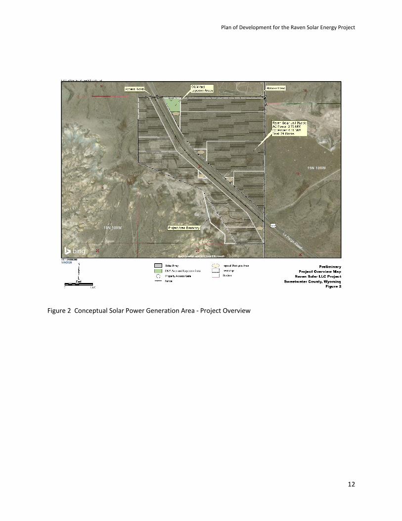
Figure 1 presents an overview of the project location including the solar energy generating facility and the gen-tie line corridor to the Raven Substation. Figure 1 will be updated during project development as more detailed information on the solar resource and environmental constraints become available. Figure 2 presents the BLM administered lands being proposed for placement of the solar energy facility, including solar modules and associated facilities. If the plan is approved, it is anticipated that project limited construction may initiate in late 2021 and full construction will begin during April of 2022, operations will commence in late 2022, and the operational lifespan for the project is anticipated to be

Plan of Development for the Raven Solar Energy Project
10
20 years with possible extension for an additional 15 years. Figure 3 presents the proposed access points to the facility off of highway WY 372. Table 1 below presents the approximate disturbance acreages and final reclamation activities.
Table 1 Approximate Surface Disturbance
Raven Solar Approximate Surface Disturbance Spreadsheet
Facility Type Type Time Frame (years)
Width (feet)
Length (feet)
Depth (feet)
Total Acreage (acres)
Interim Reclamation or Treatment
Final Reclamation Plan
Access Roads off Highway 372
Topsoil/ Removal, Road base Placement
35 35 ft 3,500 3 3 n/a Remove road base, place topsoil, and seed.
SM Connector Roads (along each SM array)
Stabilization of topsoil if required
35 20ft 10,000 1 5 n/a Remove road base/gravel, replace topsoil, and seed.
Main Roads Topsoil Removal, Road base/Gravel Placement
35 20 ft 15,000 2 7 n/a Remove road base/gravel, place topsoil, and seed.
Ground surface Under SM Arrays
Mowed Vegetation
35
320± Mow, graze, or apply soil
binder
Dependent on final design
Trenching for utilities
Excavation 1 3 26,000 3 2 n/a Replace topsoil and seed.
Fencing Crushed Vegetation
1 12 24,000 0 except
for posts 2
7 n/a Natural regrowth.
Topsoil Storage Area(s)
Mowed Vegetation
36 Varies Varies 0 12 Seed topsoil Remove stockpiled topsoil and place on previous topsoil removal areas, and seed final surface.
Directional Drilling
Crushed Vegetation
1 5 5 5 Limited to
drilling locations
n/a Replace topsoil and seed.
Operation/Maintenance Area (including O&M building, substation, refueling area, laydown yard)
Topsoil Removal, Gravel/Road base Placement
35 500-750
750 2 10 n/a Remove road base/gravel, place topsoil, and seed.
Inverter / MV transformer / BESS areas (24 pads across site)
Topsoil Removal, Gravel/Road base Placement/Concrete
35 24 x 60
24 x 80 3 ft 1
Remove concrete, place topsoil, and seed.
Geotechnical Drilling
Crushed Vegetation
1 1 1 TBD <1 n/a Natural regrowth.

Plan of Development for the Raven Solar Energy Project
11
Figure 1 Conceptual Project Area Overview
Plan of Development for the Raven Solar Energy Project
12
Figure 2 Conceptual Solar Power Generation Area - Project Overview

Plan of Development for the Raven Solar Energy Project
13
Figure 3 Conceptual Project Laydown / Substation Area Detail
The proposed timeline for permitting, construction, and operation, including the preparation of an EA, is as follows:
BLM- EA December 2019 through November 2020
POD November 2019
Baseline Studies November 2019
Kick-Off and Internal Scoping December 2019
Public Scoping January 2020
Internal Draft EA/FONSI Submittal to BLM April 2020
Internal Final EA/FONSI Submittal to BLM June 2020

Plan of Development for the Raven Solar Energy Project
14
EA/FONSI Made Available for Public Comment August 2020
Decision Record, EA, FONSI Submittal to BLM November 2020
Construction September 2021 to November 2022
Operations November 2022 through November 2057
This Plan of Development (POD) describes the design, location, and proposed schedule for the project. This POD supplements the SF 299 application and provides additional information for the ROW permitting process. It is the BLM’s general policy, consistent with the Energy Policy Act of 2005 and the BLM Energy and Mineral Policy (August 2008), to encourage development of solar energy in acceptable areas (BLM, 2008). The federal action would be for BLM to evaluate the project as proposed and to grant the necessary ROWs and Leases to develop the commercial solar energy facility and Raven Substation interconnection, if acceptable. In processing the application, BLM will follow the guidance set forth in the BLM Instruction Memorandum No. 2009-043, Solar Energy Development Policy Updated Guidance on Processing Right-of-Way Applications for Solar Energy Projects on Public Lands Administered by the Bureau of Land Management (BLM) (BLM/BLM, 2008). This POD has been prepared to be consistent with that policy.
BLM will prepare an Environmental Assessment (EA) or Environmental Impact Statement (EIS) under the National Environmental Policy Act (NEPA) to analyze the potential environmental consequences of construction and operation of the project as proposed by Raven Solar. The NEPA review will focus on critical, site-specific issues of concern.
As outlined in the Record of Decision (ROD) for Implementation of a Solar Energy Development Program and Associated Land Use Plan Amendments (BLM/BLM, 2005a), the project-specific analysis may tier to the Final Programmatic Environmental Impact Statement (PEIS) on Solar Energy Development on BLM-Administered Lands in the Western United States (BLM/BLM, 2005b) to the extent that the proposed project falls within the scope of the PEIS analyses. The ROD established policies and best management practices (BMPs) for solar energy development activities on BLM-administered lands and established minimum requirements for mitigation measures. These policies and BMPs were revised in 2008 in the BLM/BLM Solar Energy Development Policy (BLM/BLM, 2008) and have been incorporated into this POD, as appropriate.
This POD is based on preliminary project planning and available data. As the project is further defined through engineering, design, and permitting, certain aspects of the project described in this POD may change.
1.2 Proponents Purpose and Need for the Project 1.2.1 Raven Solar Purpose and Need The purpose of the Project is to provide solar-generated electricity from a site in western-Wyoming to meet the region’s existing and future electricity needs while providing a reliable, economical and environmentally acceptable energy resource in the region.

Plan of Development for the Raven Solar Energy Project
15
This project is important to the local economy due to the uncertain future of coal fired generation. We estimate the project will create four to five full time employment opportunities and over 100 temporary construction jobs. Additional direct and indirect employment will result from project construction and operation. The project is economically feasible with an estimated capital construction cost of $50 million, and it addresses the economic, employment, and power generation uncertainty associated with coal fired generation in the region.
1.2.2 Supplying Electricity The project will help meet the increased demand as part of load growth, regional renewable portfolio standards, electrical capacity deficits forecasted in PacifiCorp’s 2011 Integrated Resource Plan, and the policy mandates and incentives for development of new renewable energy supplies by providing 66 MW (nameplate) of electricity from a clean, renewable resource.
1.2.3 Employment During construction, an estimated average of 50 people will be employed at the project, with a peak of 100 employees. Most construction workers will be employees of construction and equipment manufacturing companies under contract to Raven Solar. Construction workers will include a mix of locally hired workers for civil and structural construction, and specialized workers for construction of the onsite electrical work, module installation, and testing. Local hiring will depend on the availability of workers with appropriate skills.
During project operation, the project will employ four to five operational personnel for project management, facility maintenance, site security, and other operation-related needs.
1.2.4 Economic Benefits Raven Solar will benefit the state of Wyoming because construction will support the local economy and add local jobs. The project is also beneficial in that it demonstrates that solar is one of many valuable natural resources in the state.
The project will result in a positive economic impact from direct and indirect payments to local businesses, workers, and government.
Need for Renewable Energy
Recent national and regional forecasts project an increase in consumption of electrical energy continuing into the foreseeable future. Renewable energy, including solar generation, is expected to provide a larger component of the diverse electrical supply in the future. Several western states have adopted renewable energy requirements or goals, and various national, regional, and state policies have been put in place that encourage and provide incentives for development of solar and other renewable energy projects. Continued increase in consumption of electricity requires development of new generation facilities to satisfy demand:
• Presidential Executive Order (EO) 13212, Actions to Expedite Energy-Related Projects, (66 Federal Register 28357), issued in May 2001, established a policy that federal agencies should take appropriate actions, to the extent consistent with applicable law, to expedite projects to increase the production, transmission, or conservation of energy.

Plan of Development for the Raven Solar Energy Project
16
• The National Energy Policy Development Group (NEPDG) recommended to the President, as part of the National Energy Policy, that the Departments of the Interior, Energy, Agriculture, and Defense work together to increase renewable energy production (NEPDG, 2001).
• The Energy Policy Act of 2005 (Public Law 109-58) encourages the development of renewable energy resources, including solar energy, as part of an overall strategy to develop a diverse portfolio of domestic energy supplies for the future. In the Act, Congress set a goal of at least 10,000 MW of approved non-hydroelectric renewable energy projects located on public (BLM/BLM-administered) lands by the year 2015.
• To address increased interest in solar energy development and to implement the NEPDG recommendation to increase renewable energy production, BLM/BLM established a solar energy development program. This program, which included the amendment of multiple land use plans, supported the Congressional direction provided in the Energy Policy Act of 2005 regarding renewable energy development on public lands, the directives of EO 13212, and the recommendations of the NEPDG.
• In 2004, the Western Governors’ Association set a goal of developing 30,000 MW of clean energy by 2015 from traditional and renewable energy sources (Policy Resolution 04-13, June 2004). This goal was reaffirmed in 2006 by Policy Resolution 06 10, Clean and Diversified Energy for the West (Western Governors’ Association, 2006).
• The Western Electricity Coordinating Council (WECC) forecasts electricity demand in the western United States. In the 10-Year Coordinated Plan Summary 2006-2015 (July 2006), the WECC stated that capacity margins were declining and that, from 2006 through 2015, annual energy use was projected to increase 2.2 percent (2.0 percent annual compound growth rate) (WECC, 2006).
• In 2009, Secretary of the Interior Ken Salazar signed Order No. 3285, Renewable Energy Development by the U.S. Department of the Interior, which establishes the development of renewable energy as a priority for the Department of the Interior (DOI). Encouraging the production, development, and delivery of renewable energy is now one of the DOI’s highest priorities and demonstrates the Administration’s desire to support renewable energy projects such as solar facilities.
• The Energy Information Administration, a statistical agency of the U.S. Department of Energy (DOE), states in the Annual Energy Outlook 2010 with Projections to 2035 that total electricity demand is projected to grow by an average of 1 percent per year from 2008 through 2035. Renewable generation, supported by federal and state tax incentives and American Recovery and Reinvestment Act funding, is projected to be 2.4-fold higher in 2035 than in 2008, with the renewable share of generation growing from 9 percent in 2008 to 17 percent in 2035. Installed Solar capacity grew by about 19 gigawatts from 2003 to 2008, a trend that is projected to continue with the installation of 39 gigawatts from 2008 to 2013.
• At least 29 states have passed some type of renewable energy portfolio standards, including Arizona (15 percent by 2025), California (50 percent by 2030), Colorado (20 percent by 2020), Nevada (20 percent by 2015), and New Mexico (20 percent by 2020).

Plan of Development for the Raven Solar Energy Project
17
1.3 Construction Schedule If the project is approved and receives all necessary permits, construction of the project is anticipated to begin in the fall of 2021 with the project becoming operational by the end of 2022. The current anticipated construction start date is October 1, 2021. Construction of the facility is expected to take approximately 12 to 14 months. Table 2 outlines a general construction schedule for the project. If project approvals are delayed, the timeframes provided in Table 2 for the various tasks would still be generally applicable.
Table 2 Anticipated Project Construction Schedule Task/Milestone Start Finish
Obtain Approvals October 2019 October 2021
Initial Construction October 2021 March 2022
Full Construction April 2022 November 2022
Solar Foundation anchors May 2022 July 2022
Electrical Collection System Construction June 2022 September 2022
Interconnecting Facilities Construction June 2022 August 2022
Operations and Maintenance Facility Construction July2022 November 2022
Solar Array Assembly and Erection August 2022 October 2022
Plant Energization and Commissioning November 2022 November 2022
Plant Substantial Completion November 2022 November 2022
Construction Punch list Cleanup November 2022 December 2022

Plan of Development for the Raven Solar Energy Project
18
1.4 Authorizations, Permits, Reviews, and Approvals This section summarizes the authorizations, permits, reviews, and approvals required for the Raven Solar project. Raven Solar will conform to the ROD for the Solar Energy PEIS and other applicable federal, state, and local statutes, regulations, and plans. Table 3 shows some of the potential federal, state, and local permits, authorizations, and approvals that may apply to the project. Table 3 will be updated during project development.
Table 3 Summary of Potential Federal, State, and Local Permit Requirements and Authorizations Jurisdiction Permit/Decision Trigger/Nexus
Federal
U.S. Army Corps of Engineers (USACE)
Clean Water Act Section 404- Individual or Nationwide Permit; Preconstruction Notification
Discharge of dredged or fill material into waters of the United States, including wetlands.
BLM ROW Authorization-Lease issuance
NEPA Compliance
Impacts to BLM administered lands require ROW authorization and NEPA analysis.
U.S. Fish and Wildlife Service (USFWS)
Endangered Species Act Section 7 Consultation/ Biological Opinion including consultation for water depletions to the Colorado River System.
Planning under the Migratory Bird Treaty Act
Potential take of federally listed species or their critical habitats
Impacts to migratory birds
U.S. Environmental Protection Agency
The Spill Prevention Control and Countermeasure (SPCC) Plan is a federal requirement (40 Code of Federal Regulations [CFR] 112) for facilities that store specific amounts of petroleum products.
Use of aboveground oil storage tanks on site.
Federal Aviation Administration (FAA)
Notice of Proposed Construction – not applicable if no airport near than 3 miles away
FERC- Federal Energy Regulatory Commission
FERC form 556- Qualifying Facilities Completed
Federal Communications Commission (Licensed Microwave Study)
N/A
State
TBD TBD
Local
Sweetwater County
WYDOT-ROW
Conditional Use Permit TBD
ROW along Wyoming Highway 372 is required

Plan of Development for the Raven Solar Energy Project
19
SECTION 2
General Facility Description, Design, and Operation The Project is currently designed to be constructed in one phase. The project will interconnect into a 34.5/230-kV Raven substation owned by PacifiCorp. The legal land descriptions of BLM lands included in the facility are as follows:
Table 4 Project Location Township Range Section Facility
20N 109W 20 Raven Substation
19N 109W 3, 11,13,14 Gen-Tie
19N 109W 24 SM
2.1 Solar Energy Facility Components The Project will include the following principal components:
· Up to 341 acres of SM
· Electrical wiring, string invertors, fuses, switches etc.
· An access road system
· An O&M facility
· A supervisory control and data acquisition (SCADA) system and fiber optic communication system
· Utilities
· A 34.5-kV underground gen-tie line linking the project generation to the Raven electrical substation owned by PacifiCorp
Currently, no above ground transmission line is anticipated for the project; however, a short above ground interconnection line within the project boundary and or in the Highway 372 ROW may be necessary to connect to the 34.5/230-kV Raven substation where environmental constraints make it the least impactful approach
2.1.1 Solar Modules (SM) The SM will be generally arranged in linear arrays as allowed by topography and other environmental constraints. Spacing of the arrays and SM along the arrays will vary as a function of the SM model installed. Figure 2 illustrates a conceptual placing of SM array locations that will be modified through the project development and permitting process. The SM and the associated electrical collection systems and connector roads will be situated within and between the SM arrays. The number and precise location of SM within any array will depend on the design and final engineering, model and size, resource constraints, and other factors such as civil engineering constraints or Meteorological data refinements.

Plan of Development for the Raven Solar Energy Project
20
Specifications of the currently proposed SM model are summarized Attachment A. Solar modules will be fitted into solar arrays holding a certain number of modules in a frame. Typically, nine -12 modules will fit into an array resulting in maximum height of under 10 feet and width eight to 10 feet.
Figure 4 Typical Solar Module Configuration
Depending on equipment availability, different combinations of MS types could be installed at the project. The total generating capacity of the project will be up to 66 MW-AC. SM is produced using Crystalline Silicon material.
2.1.2 Solar Tracker and Actuator (Drive) Trackers direct solar panels or modules toward the sun. These devices change their orientation throughout the day to follow the sun’s path to maximize energy capture. In photovoltaic systems, trackers help minimize the angle of incidence (the angle that a ray of light makes with a line perpendicular to the surface) between the incoming light and the panel, which increases the amount of energy the installation produces.
Single-axis solar trackers rotate on one axis moving back and forth in a single direction. Different types of single-axis trackers include horizontal, vertical, tilted, and polar aligned, which rotate as the names imply. The tracker is powered by motors and gear trains direct active solar trackers by means of a controller that responds to the sun’s direction. The use of solar trackers can increase electricity production by around a third, and some claim by as much as 40% in some regions, compared with modules at a fixed angle.

Plan of Development for the Raven Solar Energy Project
21
2.1.3 Tracking Mounting SM is inserted into pre-fabricated framing that is delivered to the project site and anchored into the ground.
Figure 6 Tracking Mounting 2.1.4 Steel Posts Anchoring Steel posts are used as structural support for the PV array. Energy of Utah utilizes custom-designed post-driving machines that have nearly doubled installation speed while reducing costs.
Figure 5 Solar Tracker and Actuator

Plan of Development for the Raven Solar Energy Project
22
Figure 7 Steel Posts Anchoring 2.1.5 Inverter Units We are anticipating using the GGE LV 5units allowing for superior grid modeling at 50 or 60 cycles. Inverters play a crucial role in any solar energy system and are often considered to be the brains of a project, whether it’s a 2-kW residential system or a 5-MW utility power plant. An inverter’s basic function is to “invert” the direct current (DC) output into alternating current (AC). AC is the standard used by all commercial appliances, which is why many view inverters as the “gateway” between the photovoltaic (PV) system and the energy off-taker.
2.1.6 Electrical Collection System A transformer at each SM string will transform the power generated by the SM through its inverters onto a step-up transformer to a 34.5 kV for delivery to the Raven substation via the underground electrical collection system. The collector cable is typically buried 36-48” underground in tri-cable configuration plus fiber optic control cable.
Although we do not anticipate installing any of our collector lines overhead, there may be instances in which this installation may minimize any environmental impact and may be considered.
2.1.7 Electrical Substation and Switchyard The Raven substation steps-up the voltage of the power being delivered by the electrical collection system to 230 kV for delivery to the PacifiCorp transmission line. Our intention is to interconnect via the low side of the 34.5 KV transformer. Details of the physical interconnection into PacifiCorp’s switchyard will be provided when available. The location shown on Figure 1 is conceptual in nature only as the final point of interconnection is yet to be determined.
The onsite substation will occupy an approximately 3 acres of graveled area. Transformers will be non-polychlorinated biphenyl (non-PCB), oil-filled types. Additional substation equipment will include circuit breakers, power transformer(s), bus and insulators, disconnect switches, relays, battery and charger, surge arrestors, alternating and direct current supplies, control house, Meteorological equipment,

Plan of Development for the Raven Solar Energy Project
23
SCADA provision, grounding, and associated control wiring. Other proposed substation equipment includes back-up power supply equipment and fuel storage (see Utilities, below). The substation site will be surrounded by an eight-foot-high chain-link fence topped with barbwire.
Figure 8 Typical Electrical Substation 2.1.8 Battery Energy Storage System Battery energy storage systems (BESS) are a growing technology in the broader renewable energy industry landscape. Battery energy storage systems are the modern version of previously used pumping or other energy storage systems which allow one power grid operator to store energy for a limited amount of time and release this energy on demand during peak demand. The BESS units for this project are anticipated to be located throughout the solar array adjacent to the invertors.
Modern BESS feature numerous advantages over previous technologies as they are using the most advanced battery technologies coupled with highly accurate power transforming equipment to provide reliable energy to the grid. BESS are becoming a key player in power stability and ultimately serving the communities to reduce cost and power outages. BESS can be deployed in just a few months with no specific terrain / geological requirements and with limited impact to natural features of the sites, as opposed to conventional energy storage (pumping or compressed air) which require significant civil work. A typical BESS offers round-trip efficiency of over 85 percent which outperforms any conventional storage system.
All BESS include three main components:

Plan of Development for the Raven Solar Energy Project
24
• Storage that accumulates electric power in battery cells made with lithium and other metals. The battery cells are incorporated into battery packs with cooling systems and enclosed in standard 40 feet containers including fire suppression systems and temperature control systems.
• Power conversion systems (PCS) that convert the batteries electric power from DC to AC at low voltage. These are very similar to PV power inverters with the exception that they allow transformation both ways: from AC to DC and from DC to AC. The PCS used are the most advanced equipment on the market and allow extremely rapid response to grid instability issues, contributing to greater grid stability.
• Energy Management System (EMS) is the control part of the BESS and allows the grid operator to remotely control the flow of energy from, or to the battery, monitor safety indicators and provide responses to grid events.
The energy systems come with a state-of-the-art level of safety components to protect the safety of people and of the assets, including a two-level fire suppression system built-into each battery container. Level 1 fire suppression includes early detection of combustion byproducts and release of a primary dry extinguishing agent. If the temperature continues to climb, the secondary (backup) extinguishing agent is released. Water is one of the best extinguishing agents due to the ability to cool the involved material and provide a thermal barrier to inhibit cascading failures.
A typical 66MW – four-hour BESS can store and deliver 66MW of power to the grid for four hours. The BESS is deeply integrated into the adjacent solar plant, with BESS sharing some components with the solar panels, including PCS and EMS. Adding a BESS component to a solar plant typically does not increase the foot print of the plant and will strongly contribute to grid stability and the plant’s ability to meet power demand.
2.1.9 Access Roads and Connector Roads Access to the project site is expected to be from newly constructed or improved gravel roads off U.S. Highway 372. Primary access is from Interstate 80 -Exit Highway 372 N. Construction details will depend on guidance and input from Wyoming Department of Transportation on construction of access roads from Highway 372 onto the BLM land.
New project roads will be constructed to support project construction and operation. Number and length of roads will be minimized to the extent possible to reduce surface disturbance. These roads include:
· SM connector roads along each SM array to provide access to each array string
· A main road connecting most of the SM arrays
· Additional roads connecting some of the SM arrays
All roads will be constructed in accordance with BLM standards and are expected to have a permanent travel width of 12-16 feet and a gravel road base. Following construction, the 12-foot-wide shoulders on either side of all permanent roadways will be stabilized by spreading stored topsoil and seeding these areas.

Plan of Development for the Raven Solar Energy Project
25
Turnarounds would be constructed near the ends of a few array roads to provide sufficient space for SM component delivery trucks and construction equipment to turn around. Turnarounds typically will be positioned strategically in the array and will consist of graveled driveways to connector road. The turnaround will be reduced to minimum size to reduce surface disturbance.
2.1.10 Operations and Maintenance Facility The Operations and Maintenance (O&M) facility will be located within the project area along a main access road. The O&M facility will include: a one-story main building with offices, spare parts storage, restrooms, a vehicle maintenance area, and a shop area; outdoor parking and a turnaround area for large vehicles; and outdoor lighting directed downwards to avoid night sky impacts. The location is yet to be determined.
A typical O&M building is shown in Figure 9. The permanent footprint of the O&M facility (including parking and storage areas) will be approximately three acres, and the O&M building itself will occupy approximately 5,000 square feet. The building will be painted to blend with the surrounding landscape.
Figure 9 Typical O & M Building
An additional storage building for parts and equipment may be constructed or incorporated into the O&M building. Other O&M facility equipment includes back-up power supply equipment and fuel storage.
2.1.11 Supervisory Control and Data Acquisition System and Fiber Optic Communications The project will include a SCADA system to collect operating and performance data from each SM array and the solar energy facility as a whole to provide for remote operation of the facility.
The SM will be linked to a central computer in the O&M building by a fiber optic network. The fiber optic cables used for SCADA communication will be placed in the trenches used for the electrical collection system and in the trench carrying the electrical connection from the substation to the O&M building.
A separate data concentrator will also be installed at the onsite substation to provide control information to the Transmission Provider’s/Balancing Authority’s dispatch center.

Plan of Development for the Raven Solar Energy Project
26
Figure 10 SCADA System
2.1.12 Utilities Utilities will be primarily associated with the O&M facility and onsite substation and will include an electrical supply for station service at both sites. Propane for heating, cistern for water and a septic tank will be provided at the O&M facility. The O&M water cistern will be located within or near the O&M facility; water from this cistern will be used for sanitary and kitchen uses. Water use at the O&M facility is estimated at 500 gallons per day or less.
Primary electrical service to the substation will be provided by either a direct connection from a local distribution line or from an auxiliary transformer off the substation 34.5-kV bus. Backup power will be provided by a standby generator.
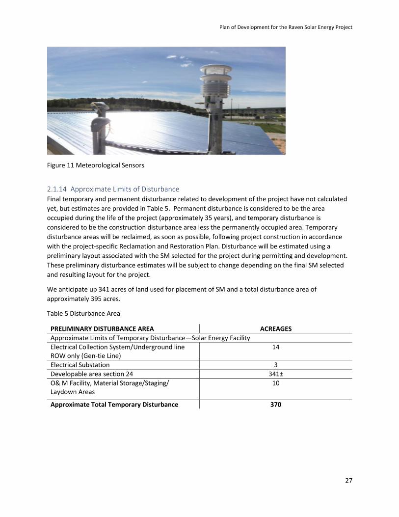
2.1.13 Meteorological Sensors Several meteorological sensors (MS sensors) will be erected at the array to monitor and adjust SM performance to minimize damage caused by wind.
Plan of Development for the Raven Solar Energy Project
27
Figure 11 Meteorological Sensors
2.1.14 Approximate Limits of Disturbance Final temporary and permanent disturbance related to development of the project have not calculated yet, but estimates are provided in Table 5. Permanent disturbance is considered to be the area occupied during the life of the project (approximately 35 years), and temporary disturbance is considered to be the construction disturbance area less the permanently occupied area. Temporary disturbance areas will be reclaimed, as soon as possible, following project construction in accordance with the project-specific Reclamation and Restoration Plan. Disturbance will be estimated using a preliminary layout associated with the SM selected for the project during permitting and development. These preliminary disturbance estimates will be subject to change depending on the final SM selected and resulting layout for the project.
We anticipate up 341 acres of land used for placement of SM and a total disturbance area of approximately 395 acres.
Table 5 Disturbance Area
PRELIMINARY DISTURBANCE AREA ACREAGES Approximate Limits of Temporary Disturbance—Solar Energy Facility Electrical Collection System/Underground line ROW only (Gen-tie Line)
14
Electrical Substation 3 Developable area section 24 341± O& M Facility, Material Storage/Staging/ Laydown Areas
10
Approximate Total Temporary Disturbance 370

Plan of Development for the Raven Solar Energy Project
28
SECTION 3
Project Construction This section describes the types of construction activities associated with developing a typical solar energy facility. Information specific to the Raven Solar project is included as appropriate. This section also includes information on the health and safety and environmental programs that will be implemented during project construction.
3.1 Preconstruction Activities Project preconstruction activities, which are applicable to the solar energy facility, are discussed in this section, including siting project features, conducting preconstruction surveys, acquiring public ROWs and surface easements, and planning construction transportation.
3.1.1 Project Component Siting Siting of the solar energy facility was based on TMY 2, and NREL data and observations indicating that the selected site is optimal for exploiting the suitable solar resource available in the general area as well as consideration of environmental constraints. The proposed gen-tie location is located in the WY 372 ROW to minimize impacts to environmental resources. A large portion of the site and nearby areas are currently impacted by extraction of various mineral resources such as trona and gravel and contain industrial facilities for the processing of trona and associated products. The siting of a solar energy facility in this area will conform to the existing land use. The project area is zoned as an Agricultural District by Sweetwater County, and a variety of land uses occur in this district, including agriculture, extractive uses, and rangeland. Another factor in the selection of the site is its remote location, roughly 14 miles away from Green River and located on high elevated plateau, limiting any visual impact to permanent residences.
At the project site, the SM will be arranged in linear arrays as practicable. Final layout will be a function of suitable land, resource constraints, and other factors such as engineering constraints or geological data refinements. The associated electrical collection systems and solar array connector roads will be situated within the SM arrays. The layout will reflect setbacks of the SM from identified project constraints, such as but not limited to, State roads and from non-participating private property that are consistent with general practice and applicable guidance for solar PV.
Flexibility is included in the preliminary siting plans for the SM. Certain adjustments of infrastructure locations may be required based upon environmental and engineering constraints. For example, adjustments may be made in the locations of project features based on the identification of sensitive environmental resources or National Register of Historic Places (NRHP) eligible cultural resources in the vicinity of preliminary facility sites. Project facilities will avoid perennial or intermittent streams and wetlands. If necessary, any final adjustments to the location of facility structures on BLM lands to avoid important resources will be coordinated with the BLM.
3.1.2 Preconstruction Surveys The project site will be surveyed to delineate SM array ROW boundaries, substation and O&M facility boundaries, and access road and electrical collection cable centerlines. Temporary use areas, cultural resource sites, and environmentally sensitive areas within the project boundary will be field delineated, where appropriate, to assist in avoiding such areas during project construction.

Plan of Development for the Raven Solar Energy Project
29
3.1.3 Flagging Plan Raven Solar will survey and clearly mark the centerline and exterior limits of each SM array ROW corridor at approximately 200-foot intervals or as determined by the BLM authorized officer. Construction activities will be confined to the staked and flagged areas. Raven Solar will also set centerline stakes to identify the location of proposed roads. Survey station numbers will be marked on the boundary stakes at the entrance and exit of public lands.
Markers will be used to limit access within work and travel areas to restrict construction access from unnecessarily disturbing important cultural and environmentally sensitive areas. Buffer areas for cultural resource sites will be staked and flagged by a qualified archaeologist. No surface disturbance or construction activity will be allowed within the marked restricted areas. Staking of the different use areas will be painted and/or flagged with different colors as listed in Table 6.
Table 6 Flagging Colors Color Use
White ROW centerline
Orange Exterior limits of ROW
Blue Road centerlines
Green Temporary work areas
Red Environmental restrictions
If stakes are disturbed, they will be replaced. Raven Solar will maintain boundary stakes in place until final cleanup and restoration has been completed and/or approved by the BLM authorized officer. Stakes will then be removed at the direction of the BLM authorized officer.
3.1.4 Geotechnical Investigations and Testing In addition to geotechnical site evaluations that will be completed prior to construction, additional geotechnical testing may be required during construction to establish engineering data suitable for evaluation of potential SM sites in order to finalize SM array layout and for use in foundation design.
The following geotechnical exploration methods may be used, and are described in more detail below:
· Cone penetration testing (CPT)
· Dilatometry testing (DMT)
· Hollow-stem auger (HSA) Drilling
· Rock coring / ODEX drilling
· Test pit excavations
· Soil Resistivity (Electrical and Thermal Properties)
Geotechnical testing begins with CPT, and additional tests may be performed at some locations depending on the results of initial data collection. Flat-plate DMT testing would be performed at test sites where CPT testing identifies the need for DMT or to provide spatial coverage of the site. HSA soil

Plan of Development for the Raven Solar Energy Project
30
drilling and rock coring may be performed in some cases following or in-lieu of CPT testing. Rock coring would only be used where the HSA encounters refusal. Test pit evacuations would be used where field conditions indicate that excavation is necessary at specific sites. The exact sequence of field tests will depend on site conditions and rig schedules. With few exceptions, the terrain in the area of the proposed solar energy facility and the transmission line is relatively flat. Geologic hazards associated with steep slopes, deep ravines and washes are to be avoided as unsuitable for solar PV.
3.1.5 Cone Penetration Testing The CPT testing methodology entails the use of several technologies centered on driving a 2 inch-diameter cone into the ground. This allows for collection of information on soil resistance based on movement of the cone through the soil and measurement of shear wave generation (at all SM array locations) and velocity wave generation (10 to 15 percent of the SM locations). It is anticipated 10 to 15 percent of the SM locations will also undergo pore pressure dissipation testing, which is a measurement of soil drainage characteristics. CPT testing will typically extend to a depth of 10 to 25 feet. CPT testing results in minimal refuse and tailings from the insertion and retrieval of the testing equipment.
CPT testing is anticipated to take less than two hours at each test site for CPT sounding, shear wave testing, velocity wave testing (if performed), and pore pressure dissipation testing (if preformed). These tests are performed by the CPT rig during the initial advancement of the CPT rods and cone.
CPT testing requires a track-mounted CPT rig, CPT support vehicle, and geotechnical contractor support vehicle. The track-mounted CPT rig is 25 feet long, 10 feet wide and 12.5 feet high. The CPT support vehicle is 8.5 feet wide, 22 feet long and eight feet high. The geotechnical contractor support vehicle is generally either a standard pickup truck or sport utility vehicle (SUV).
The CPT testing work area would be located beneath the CPT rig. An approximately 30-foot by 30-foot parking and foot traffic area near the CPT rig would be used for testing activities.
3.1.6 Flat-Plate Dilatometry Testing DMT is a measurement of soil elasticity. DMT testing is conducted with the CPT rig, but DMT testing requires a second advancement of the CPT rod using a flat-plate dilatometry instead of the CPT cone. DMT testing will typically extend to a depth of 10 to 25 feet. DMT testing produces no drill cuttings or other investigation-derived wastes.
DMT testing is anticipated to take less than two hours and may or may not occur during the same trip as CPT testing. DMT testing requires the same support vehicles and disturbance footprint as CPT testing.
3.1.7 Hollow-Stem Auger Drilling It is anticipated that a 3-1/4-inch HSA will be used for soil sampling, where necessary. The HSA rotates as it is driven into the ground. A plug prevents soil from entering the hollow portion of the auger during drilling, and the sample is taken by retracting the plug and lowering the sample tube down through the auger. For a 3-1/4-inch hole, approximately 0.2 cubic yard of soil refuse is produced per 60 feet of hole depth. This refuse soil will be backfilled into the hole, and any excess will be distributed around the adjacent area. Each HSA borehole will be extended to a nominal depth of 10 to 25 feet.
The HSA method will require one three- to four-hour trip to each site selected for drilling. Vehicles on site will include a truck-mounted auger, an auger rig support truck, and a geotechnical contractor support vehicle. The auger rig is approximately 25 feet long, 8.5 feet wide and 12.5 feet high. The auger
Plan of Development for the Raven Solar Energy Project
31
rig support truck is 25 feet long, 8.5 feet wide and nine feet high. The support vehicle will be a pickup truck or SUV.
An approximately 30-foot by 40-foot parking and foot traffic area would be used for HSA drilling activities. The actual drill work area would be an additional 10 feet by 10 feet.
3.1.8 Rock Coring/ODEX Drilling If HSA drilling encounters refusal and is unable to reach the desired depth for sampling, rock-core drilling would be required. Rock coring would generally extend to a depth of 30 feet or until a 10-foot core run is obtained. Samples will be removed from the core barrel and packaged for later inspection, and rock cuttings will be removed by circulating water through the core barrel. The water and small quantities of rock cuttings will be dispersed on the ground surface around the coring location.
ODEX soil drilling techniques are the same as described for HSA drilling, except that an ODEX drilling head and temporary casing are used instead of the HSA auger and cutting head. If ODEX drilling methods are used for the soil drilling and a direct switch to coring is performed, one to two hours (in addition to soil drilling time) would be required per core, depending on depth and rock quality encountered. If HSA drilling methods are used for the soil drilling, predrilling to reach the top of rock would be required. If necessary, rock coring would require a separate trip to the test site and three to four hours to complete the rock core.
Rock coring/ODEX drilling vehicles include a track-mounted rotary rig, water truck, support trailer, rotary rig support truck, and geotechnical contractor support vehicle. Vehicle dimensions are as follow:
· Track-mounted rotary rig—10 feet long (rig only), 19 feet long (with mast); seven feet wide; nine feet high (mast down), 25 feet high (mast up)
· Water truck—33 feet long, 8.5 feet wide, 12.5 feet high
· Support trailer—38 feet long, 8.5 feet wide, 12.5 feet high (with drill rig loaded)
· Rotary rig support truck—18 feet long, 8.5 feet wide, 7.5 feet high
· Geotechnical contractor support vehicle—pickup truck or SUV
The anticipated parking and foot traffic area for rock coring/ODEX drilling is approximately 40 feet by 40 feet, with an additional 10-foot by 10-foot drill area.
3.1.9 Test Pit Excavation Test pit excavations will be created with a standard backhoe. Soil will be removed from an approximately five-foot-by-five-foot area to a depth of approximately five feet (maximum anticipated depth of seven feet). The excavation will allow visual observation of subsurface conditions and the extent of underground rock formations and will provide a bulk soil sample for electrical thermal resistivity measurements. Excavated soil will be returned to the pit immediately upon completion of excavation. Excavation, sampling, and backfilling of test pits can be performed in one to two hours. If it is necessary to leave a test pit open overnight, a substantial barrier would be erected around the excavation to prevent entry by wildlife or livestock.

Plan of Development for the Raven Solar Energy Project
32
Equipment for excavating test pits include a standard rubber-tired backhoe and geotechnical contractor support vehicle (pickup truck or SUV). Test pit work areas are typically the test pit area (five feet by five feet) and adjacent soil pile. The parking and foot traffic area would be approximately 25 feet by 25 feet.
3.1.10 Non-Invasive Testing Non-invasive testing would include visual evaluation of the soil surface at the testing location and electrical resistivity testing. No soil, rock, or vegetation would be excavated or removed by these non-invasive test methods.
3.1.11 Soil Resistivity Small probes connected to a small suitcase size controller will be inserted in the ground at surface level or in a Test Pit Excavation to measure electrical and thermal properties of the soil. Small samples of the soil maybe taken and shipped to a laboratory for further testing.
3.2 General Construction Information General construction information and practices applicable to both the solar energy facility are discussed in this section.
3.2.1 Construction Schedule Construction of the solar energy facility will occur concurrently and would be accomplished by two or more construction crews specializing in various construction components. The overall construction period is estimated to be approximately 12 months (see Table 2).
3.2.2 Construction Work Force During the approximately 12-14 months construction period, monthly employment is anticipated to peak at about 100 onsite jobs (but likely to remain at 50 employees for most of the time).
Raven Solar will use qualified local and/or non-local contractors and subcontractors according to the equipment and personnel needs of the project. Raven Solar anticipates that a large percentage of the work force would be from Wyoming if qualified, although specialty workers from various parts of the country may be required.
3.2.3 Construction Transportation Trucks transporting solar PV components, frames, and other construction materials will access the project from U.S. 372 and then along project roads to material storage, staging and laydown areas.
None of the trucks bringing SM components to the project site will be oversized and it is not anticipated that any major road improvements will be needed to accommodate delivery and construction traffic along the public roads and highways.
No railroad crossings will be required to access the project. Crossing and work in the ROW of Wyoming Highway 372 will be required.
Equipment and material hauling will be performed in such a manner as to prevent damage to areas outside the project and to minimize interference with normal uses of lands crossed. A Transportation Management Plan will be developed to address issues specific to accessing the WYDOT ROW for construction of the gen-tie line and crossing the highway in the solar power generation area.

Plan of Development for the Raven Solar Energy Project
33
Transportation and construction contractors will obtain all necessary permits for transportation-related elements of the project from the Wyoming Department of Transportation.
Additionally, the Traffic Management Plan will identify site access points to minimize potential hazards from increased truck traffic and worker traffic and to minimize impacts on traffic flow in the vicinity of the project. During construction, a 15 mile-per-hour (mph) speed limit will be observed on BLM ROWs. Travel on other access roads will be as posted or determined safe speeds.
Figure 12 Typical Equipment Delivery Truck (and Offloading)
3.2.4 Construction Vehicle Maintenance Routine vehicle and equipment maintenance activities will be performed off site or within the material storage, staging and laydown areas, or in the field where they are stopped. Broken-down vehicles or equipment will be trucked or towed off site for repair.
3.2.5 Special Work Areas 3.2.5.1 Residential Areas The closest rural residence is present approximately three miles to the northeast of the proposed project site, on the east side of the Green River. Other residences are over 20 miles east of the project site. The entire project area is located on a high plateau minimizing visual impacts.
3.2.5.2 Agricultural Lands The BLM will notify livestock grazing permittees prior to construction on their allotments (if any). The project proponent will discuss loss of forage with the BLM and the livestock grazing permittee. Other protection measures will include the segregation and conservation of topsoil, as appropriate. Rock brought to the surface by construction activities will be buried or removed during restoration. Weed control measures will be implemented, and revegetation will be performed, as required by the BLM authorized officer.

Plan of Development for the Raven Solar Energy Project
34
3.2.5.3 Fences and Other Improvements Raven Solar will minimize disturbance to existing fences and other improvements and will promptly repair damaged improvements to their original state or better. Functional use of these improvements will be maintained at all times.
Fences crossed for transportation access will be braced and secured to prevent slacking of the wire before cutting. Before fences on public lands or fences between public and private lands are crossed, BLM will offer grazing allotment permittees an opportunity to be present when the fence is cut so they may be satisfied that the fence is adequately braced and secured. Openings in the fence will be temporarily closed as necessary during construction to prevent passage of livestock.
If construction disrupts or destroys a natural barrier used for livestock control, the openings will be fenced to prevent livestock passage. Permanent roads through fences may require cattle guards or gates for access. These features will be constructed to BLM specifications.
Raven Solar will work with BLM on appropriate permanent fencing to protect the facility per all local, state and federal regulations and electrical code regulations.
3.3 General Construction Methods This section describes general construction methods applicable to the solar energy facility.
3.3.1 Clearing and Grading In general, clearing and grading will be necessary for new roads, the collection system, the O&M facility, and material storage, staging and laydown areas. Clearing and grading will be required in some areas to allow for movement of construction traffic, operation of construction machinery, and placement of excavated materials within the solar energy facility site during construction. Clearing and grading will not typically be required for the crane paths except as required by local topographic conditions.
Clearing, grading, and other disturbance of soil and vegetation will be limited to the minimum area required for construction. In many areas, clearing or grading will involve only the proposed temporary work areas listed in Table 5, in order to reduce potential impacts on existing resources. Where possible only mowing of the existing prairie will be conducted.
Clearing of areas will be accomplished using a standard bulldozer, grader, or other similar earthmoving equipment. All the disturbed areas will be covered with materials following construction to aid in erosion control and create wildlife habitat.
In vegetative types other than shrub habitats (for example, grassland or scrubland), clearing will consist of leveling the area for support of construction equipment and permanent project facilities. In relatively flat areas that will not be occupied by permanent structures, clearing may only involve “scalping,” which would involve cutting shrubs near the base and leaving the root structure in the ground to minimize soil disturbance. These areas would be accessed by a “drive and crush” method, and no grading would be required. This construction method will minimize disturbance of soils and vegetation. Grading will require that topsoil is stockpiled and that affected areas are reseeded after construction is complete. The project area does not contain any vegetation taller than sagebrush based on our extensive field visit. Raven Solar will prepare a Construction Reclamation Plan to address regrading and revegetation of areas temporarily disturbed by construction.

Plan of Development for the Raven Solar Energy Project
35
3.3.2 Topsoil Removal and Protection Topsoil material that is suitable for site reclamation will be removed in conjunction with clearing and grading and reserved in stockpiles.
Erosion control measures will be employed in areas where surface disturbance and/or slope leave the soil susceptible to wind and water erosion. BMPs developed in the project SWPPP or required by the Solar Energy PEIS (see Appendix A), and other site-specific BMPs, will be implemented, as appropriate.
3.4 Solar Energy Facility Construction The general construction contractor(s) will prepare each SM array site; complete site civil work, including construction of access roads, installation and commissioning of SM, the project substation, and O&M facilities; oversee construction; and complete final cleanup and restoration of temporary disturbance areas.
3.4.1 Construction Equipment Construction equipment will include earth-moving equipment, including but not limited to loaders, various-sized bulldozers, graders, shovels and backhoes; assembly cranes; delivery trucks and semi tractors; welding rigs, generators, and compressors; and light-duty support vehicles. Table 7 lists the types of equipment that will likely be used during construction of the solar energy facility.
Table 7 Typical Vehicles and Equipment Used for Solar Energy Facility Construction
Activity Equipment
Road Construction Bulldozer
Motor Grader
Drum Packer
Dump Truck/”Belly” Dump Trucks
Water Truck
Rubber Tire Backhoe
Excavator
Electrical Work Cable Spool Truck
Concrete Truck
Boom Truck
Fork Truck To Offload Spools
Man-lift Bucket
Rock Trencher
Materials Transportation Truck

Plan of Development for the Raven Solar Energy Project
36
Activity Equipment
Winch Truck
Substation and Switching Station Construction
Backhoe
Bulldozer
Concrete Truck
Drill Rig
Dump Truck
Man-lift Bucket Truck
Trencher
Winch Truck
Excavator
Solar Array Assembly and Erection Boom Truck
Fork-lift
Rough Terrain Crane
Materials Transportation Truck
Truck-mounted Crane
Project Cleanup Dump Truck
Front-end Loader
Motor Grader
Dozer
Materials/Waste Transportation Truck
Daily Construction Traffic Full-size Pickups, FedEx, UPS, and Other Delivery Trucks
3.4.2 Material Storage/Staging/Laydown Areas During construction of the solar energy facility, temporary material storage, staging, laydown areas may be established to mobilize construction activities. Up to a 10-acre material storage, staging, laydown area may be used for temporary office trailers, parking for construction vehicles and construction workers’ personal vehicles, parking or storage of other construction equipment, and temporary staging and laydown for construction materials. The laydown area will consist of a crushed-gravel surface that

Plan of Development for the Raven Solar Energy Project
37
may be removed following construction, and each area will be reclaimed following construction unless otherwise specified by the landowner.
3.4.3 Solar Energy Facility Construction Refueling Fueling stations will be established on the solar energy facility to service light-duty vehicles and to fill 1,000-gallon or smaller mobile tanks mounted on trucks. These trucks will transport the fuel to heavy equipment that is refueled in place at the project site. Up to four 1,000-gallon diesel fuel tanks will be located at the solar energy facility material storage, staging, laydown areas for vehicle and equipment fueling. Two additional 1,000-gallon diesel fuel tanks will be located at the concrete batch plant site to service the concrete trucks.
Each fuel tank will be located within secondary containment. Each station will be equipped with a spill kit and will be operated consistent with the project SPCC Plan.
3.4.4 Concrete Batch Plant The project will likely not require construction of concrete foundations for each SM array, or each transformer pad. The substation equipment and the O&M building will require concrete material, but this will likely be secured from Ready-Mix operations in Green River, Wyoming. The overall quantities needed may not justify construction of an on-site batch plant.
3.4.5 Access Roads and Connector Roads Construction of the solar energy facility will require the construction of new roads to provide access for personnel and vehicles. These roads will be constructed along and between the SM arrays. Additionally, a road will be constructed along the north and east boundary of the facility to maintain access to the WDOT gravel pit adjoining the facility to the east.
Project access roads will provide permanent vehicular access to each SM array site, the substation, the O&M facility, and the MS tower(s) throughout the construction, operation and maintenance, and decommissioning phases of the project. Temporary access will be provided to construction parking areas, and material storage, staging, laydown areas during the construction phase.
The general design criteria listed below are typical for solar energy facilities and, with some variations related to terrain, access, and other engineering requirements including safety of construction and maintenance activities, these criteria will be followed at Raven Solar.
Maximum road widths:
· Total permanent road width of 16 feet
· Permanent graveled travel width of 16 feet; with the 12-foot stripped shoulders on either side being reseeded following project construction. Seed mixtures and techniques developed in consultation with BLM but retained for crane movement during operations. There are currently no plans for “special crane” paths. The offloading will occur using boom trucks.
Turning radius for turns off main access roads within the solar energy facility onto solar array connector roads:
· ~50 feet radius wherever possible

Plan of Development for the Raven Solar Energy Project
38
· Turning aprons are part of the permanent project road system
Permanent road surface:
· Road base with gravel surface
Design speed:
· 15 mph on the BLM ROW for construction
· As posted or at other safe speeds on other access roads
Access road construction will begin with site preparation, including constructing project access entryways from public roads. Because of the relatively flat terrain in the project area, very little cut-and-fill is anticipated for the access roads. Project roads will have a permanent graveled travel width of 16 feet, with 12 feet on either side to be reseeded following project construction but retained for crane movement throughout the operations phase. Permanent roads will have a road base with gravel surface. Road construction will be performed in multiple phases starting with rough grading and leveling of roadways. Once rough grade is completed, base rock will be trucked in, spread, and compacted to create a road base. In some places, a capping rock may be spread over the road base and compacted to the finished grade.
Gravel is a very abundant resource within project foot print and Raven Solar is planning to utilize this local material for road construction.
Once heavy construction is complete, a final pass will be made with the grading equipment to level out road surfaces, and more capping rock will be spread and compacted where needed. Water bars will be cut across roads as needed to allow for natural drainage of water over the road surface and to prevent road washout. Side ditches will be excavated as needed to allow for natural drainage of water away from the road surface and to reduce the potential for erosion. Excavated soil and rock will be used onsite for road construction or distributed or disposed of into several large previously excavated gravel pits. Larger excavated rocks will be buried or crushed and reused onsite as backfill or roadway material.
Site access and array string roads will generally be constructed in the following sequence:
· Stake row centerline and boundaries of roads as necessary for construction
· Install temporary stabilization features, such as silt fences, straw bales and other controls at the limits of construction
· Clear and grub area associated with road
· Separate and stockpile topsoil for later use
· Grade roads to slopes/design indicated on construction drawings
· Compact subgrade
· Install aggregate road surface
· Perform final stabilization/revegetation of disturbed areas associated with roadway corridor
Plan of Development for the Raven Solar Energy Project
39
· Remove temporary stabilization measures once final stabilization/revegetation is established
The amount of water to be used for dust suppression and to moisture condition soil for compaction during construction of project access roads and other features will be estimated.
Once construction is complete, reclamation will be initiated in areas disturbed by construction. After final grading and restoration to approximately original contours, areas on BLM-administered lands will be restored using seed mixtures and techniques developed in consultation with BLM.
After construction, all areas exhibiting soil disturbance will be surveyed for the presence of noxious weeds. Noxious weed control will continue onsite during the revegetation process and operations phase of the project according to the specifications stipulated in the project Noxious Weed Management Plan.
3.4.6 Solar Arrays The SM arrays will be assembled and erected at each site. The SM and array frame will be delivered to the specific site, off loaded and assembled using cranes and manual labor.
3.4.7 SM Array Work Area and Crane Pad Preparation The SM off loading and assembly area do not require any additional land areas other than normal use of SM Array connecting roads and surfaces.
3.4.8 Solar PV Foundation Types Foundation selection is critical for a cost-effective installation of PV solar panel support structures. Lack of proper investigation of subsurface conditions can lead to selection of the wrong foundation type and can result in costly change orders and delays to the job completion date. A complete geotechnical study will be conducted by an engineering firm which will include a limited number of test borings noting soil type, refusal, and water table. Also, the geotechnical report will note corrosive factors to help in selecting the correct type of corrosion protection needed for the foundations.
Geotechnical report will be used for recommendation on design of the specific foundation although each site may use several different foundation types if subsurface conditions vary. A pull test will be conducted after selection of foundation type in order to attempt to minimize embedment depth, and thus length and cost of screwed or driven foundations. A pull test uses a strain gauge to measure vertical and lateral resistance up to the forces required by the PV support structure engineer’s calculations for wind and snow load requirements. There are four principal types of foundations commonly utilized.
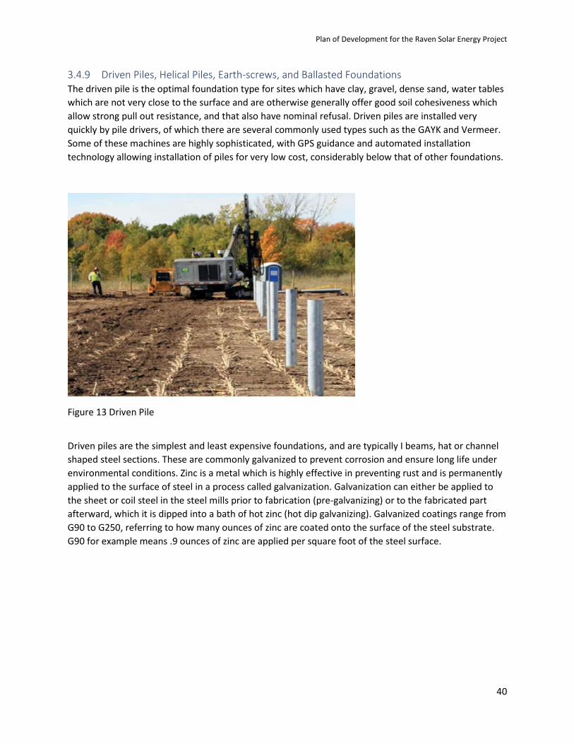
Plan of Development for the Raven Solar Energy Project
40
3.4.9 Driven Piles, Helical Piles, Earth-screws, and Ballasted Foundations The driven pile is the optimal foundation type for sites which have clay, gravel, dense sand, water tables which are not very close to the surface and are otherwise generally offer good soil cohesiveness which allow strong pull out resistance, and that also have nominal refusal. Driven piles are installed very quickly by pile drivers, of which there are several commonly used types such as the GAYK and Vermeer. Some of these machines are highly sophisticated, with GPS guidance and automated installation technology allowing installation of piles for very low cost, considerably below that of other foundations.
Figure 13 Driven Pile
Driven piles are the simplest and least expensive foundations, and are typically I beams, hat or channel shaped steel sections. These are commonly galvanized to prevent corrosion and ensure long life under environmental conditions. Zinc is a metal which is highly effective in preventing rust and is permanently applied to the surface of steel in a process called galvanization. Galvanization can either be applied to the sheet or coil steel in the steel mills prior to fabrication (pre-galvanizing) or to the fabricated part afterward, which it is dipped into a bath of hot zinc (hot dip galvanizing). Galvanized coatings range from G90 to G250, referring to how many ounces of zinc are coated onto the surface of the steel substrate. G90 for example means .9 ounces of zinc are applied per square foot of the steel surface.

Plan of Development for the Raven Solar Energy Project
41
Figure 14 Helical Pile
A helical pile is a post shape with a pointed bottom and a large split disc near the bottom welded onto the post at an angle so that when the post is rotated the split disc will worm its way into the ground. The helical pile is typically hot dip galvanized with corrosion resistant zinc after fabrication. The helical pile is ideal for locations with poor soil cohesion since it can be easily installed with auger attachments on bobcats, excavators or other equipment which rotate it into the sand. Although soil conditions with little cohesiveness such as sand with high water table provide little pullout resistance, the disc is held by the mass of the column of sand above it, creating strong pullout resistance. In order to determine embedment depth of the helical pile a pull test should be conducted which will measure the vertical and lateral forces at various embedment depths to determine where the helical pile will have sufficient resistance to satisfy the requirements of the loads determined by the PV support structure vendor’s structural engineers.

Plan of Development for the Raven Solar Energy Project
42
Figure 15 Earth Screw Foundation
An earth-screw is a steel post shape with threads welded onto or machined into it to create a large screw. After fabrication, earth-screws are typically hot dip galvanized with corrosion resistant zinc. Earth-screws are usually installed after predrilling holes into the rock or ledge and then screwing them into the holes with bobcats, excavators or other equipment using auger attachments. They can also be installed without predrilling if there are no refusal issues. The cost of installation is high due to the need for separate equipment to predrill. However, since the threads of the screw are very sticky and create substantial pullout resistance, they are less expensive then driven pile installation in sites with high amounts of refusal which typically require expensive oversized holes to be drilled and the driven piles to be installed with concrete poured around them.
Figure 16 Ballasted Foundation

Plan of Development for the Raven Solar Energy Project
43
Ballasted foundations are typically precast or less expensive Pour-in-Place concrete foundations with the PV support structures are mounted. Historically these foundations have been too expensive to consider them as a viable alternative to driven or screwed foundations, but recent price declines made possible by Pour-in-Place solutions and some declines in precast solutions have driven the cost close to other foundations in some instances. Ballasted foundations are good options where a combination of high refusal rates and low soil cohesiveness such as loose sand with high water table are present, making installation of both helical piles and earth-screws not effective as earth-screws are not effective in soils with poor cohesiveness and helical piles will not install if refusal is present. Ballasted foundations are also good options for sites which would otherwise be good for helical piles or earth-screws if the ballasted foundations are as cost effective as the other foundations in these cases when the total of install cost, ballast cost, and system cost are calculated.
3.4.10 Electrical Collection System Electrical collection system cables will be installed in underground trenches. The trenches are typically 1 to 2 feet wide and 36” to 48” deep (see Figure 17) for each circuit. In locations where two or more sets of underground lines converge, underground vaults and/or pad-mounted switch panels will be used to tie the lines together into one or more sets of larger feeder conductors. At this time, Raven Solar plans to utilize the on-site substation to PacifiCorp’s own Raven Substation via ROW along Wyoming Highway 372 for the feeder connection.
After final grading and restoration to approximately original contours, areas on BLM-administered lands will be restored using seed mixtures and techniques developed in consultation with the BLM.
Figure 17 Typical Underground Cable Trench 3.4.11 Electrical Substation The onsite electrical step-up substation will be located on an approximately 3-acre graveled site. Construction activities will include:
· Clear and grub site.

Plan of Development for the Raven Solar Energy Project
44
· Grade and Compact Substation boundary, supply fill as required.
· Construction of concrete foundations for substation equipment designed for the soil conditions at the substation site.
· Installation of substation components, including circuit breakers, power transformers, bus and insulators, disconnect switches, relays, battery and charger, surge arrestors, alternating and direct current supplies, control house, SCADA, grounding, associated control wiring, and possibly capacitor banks.
· Install perimeter fence and yard rock.
Grounding equipment would consist of a grounding grid laid below grade in trenches around the substation site or other grounding methods to protect equipment and personnel.
The substation site will be surrounded by an 8-foot-high chain-link fence topped with barbwire. The substation will be equipped with an outdoor downcast lighting system. Typical signage could include “Keep Out,” “Danger,” and “High Voltage.”
3.4.12 Operations and Maintenance Facility The O&M facility will permanently occupy approximately 3 acres at the project site. The O&M building itself would be 5,000 square feet or less in area. Construction of the O&M building would involve conventional construction techniques, with the erection of a 1 story building on a concrete foundation.
3.4.13 Meteorological Sensors These sensors are typically mounted onto the steel structures supporting solar arrays.
3.5 Testing and Calibration After construction, systems, controls, and safety equipment will be calibrated and tested before being placed in service. Qualified technicians, mechanical and electrical experts, and electricians will test and inspect solar components, transformers, communications systems, substation, and interconnection systems to ensure that they comply with required specifications and are working properly.
3.6 Site Reclamation and Revegetation The final phase of construction is clean-up and reclamation of areas disturbed by construction but not required for facility operations. The following represents minimum requirements for areas disturbed by the construction process. Specific requirements and additional details will be included in a Construction Reclamation Plan prepared for this project.
Areas that have been temporarily disturbed by grading or other earthmoving activities will be restored to the original contours of the land to the extent possible and consistent with future operating needs. Reclamation work may consist of recontouring eroded areas, extending water bars, creating berms, installing rock barriers, establishing vegetation, and applying mulch to provide additional erosion control. Ungraded areas disturbed only by overland travel will be assessed in coordination with BLM to determine if reclamation is needed for recovery of the area.
Disturbed areas on BLM-administered lands will be revegetated as determined necessary by BLM. Temporary disturbance areas will be revegetated using seed mixtures and techniques developed in consultation with the BLM. The Construction Reclamation Plan includes success criteria and monitoring

Plan of Development for the Raven Solar Energy Project
45
protocols to assess how successful revegetation efforts have been and to determine whether additional reclamation efforts are needed.
Noxious weed control will continue onsite during the revegetation process according to the specifications that will be stipulated in a Noxious Weed Management Plan prepared for the project.
Upon completion of construction and reclamation, fences and other previously existing structures will be reestablished to as good a condition or better than the original.
3.7 Health and Safety Program Raven Solar will conduct a safety assessment to identify potential safety issues and to develop measures that would be employed to mitigate them. Potential safety issues include site safety and security, emergency response procedures, fire control, safe work practices, heavy equipment transportation, and traffic management. A health and safety program will be developed to protect both workers and the general public during project construction and documented in a Health and Safety Program Plan.
3.7.1 Site Safety and Security Raven Solar will post warning signs along the project access roads informing the public of construction activities and recommending that the public not enter the site. For areas where public safety risks could exist and site personnel would not be available to control public access (such as excavated foundation holes and electrical collection system trenches), warning signs and temporary fences will be erected. Fencing may also be installed around material storage, staging, and laydown areas. Other areas determined to be hazardous or where issues of security or theft are of concern may also be fenced in coordination with BLM. Temporary fencing around unfinished PV array, excavations, and other hazards will typically be a high-visibility plastic mesh. If deemed necessary, Raven Solar may also use security guards, cameras, and/or additional fencing to protect public health and safety and project facilities.
Raven Solar’s general contractor will develop a construction Site Safety Plan for the project. The Site Safety Plan is a general health and safety plan that addresses the zero-injury safety policy, responsibilities and roles of personnel, health and safety for subcontractors, worker safety orientation and training, severe weather conditions, and accident/incident reporting procedures. The Site Safety Plan also outlines employee safe work programs, including drug and alcohol policies, hazardous materials, fire protection, respirator use and maintenance, confined workspaces, and potential work hazards such as blood-borne pathogens, electrical hazards, and environmental dangers. Raven Solar’s general contractor will coordinate with BLM regarding the various components of the Site Safety Plan, such as training and reporting accidents.
3.7.2 Emergency Response Raven Solar’s general contractor will develop an Emergency Response Plan for construction of the project. The Emergency Response Plan details emergency procedures, including emergency recognition and prevention, organization and personnel responsibilities, emergency alerting procedures, maps and diagrams of the facilities, incident documentation, investigation responsibilities, and post-emergency activities. Specific emergency procedures for medical, severe weather, power outages, and other situations will also be addressed in an Emergency Response Plan. The Emergency Response Plan will be amended to the POD when completed.

Plan of Development for the Raven Solar Energy Project
46
The general construction contractor will be responsible for implementing the Emergency Response Plan in the course of all work performed by the general contractor and all site subcontractors during project construction and for coordination with local first responders.
3.7.3 Fire Safety Raven Solar’s general contractor will develop a Fire Safety Plan to minimize the potential for a human-caused fire. The Fire Safety Plan addresses potential fire sources and appropriate safety and fire prevention measures. Project-specific potential fire sources include vehicle exhaust systems, fueling operations, smoking, electrical work, and onsite flammable liquid storage. Fire suppression, emergency preparedness, and emergency notification and follow-up procedures are also addressed, and BLM fire guidelines for equipment use and other measures such as carrying fire extinguishers and shovels are incorporated into the Fire Safety Plan.
3.7.4 Blasting Raven Solar does not anticipate any blasting to be required.
3.7.5 Transportation Management Equipment and material hauling will be performed to prevent damage to areas outside the project and to minimize interference with normal uses of lands crossed. To this end, Raven Solar’s transportation contractor will develop a Transportation Management Plan to address issues specific to transporting SM components, main assembly cranes, and other large pieces of equipment, as well as construction equipment, including trucks, loaders, various-sized bulldozers, shovels and backhoes, welding rigs, generators, and compressors.
The Transportation Management Plan describes regional and local access routes and affected roadways, traffic volumes, pavement conditions, and traffic mitigation measures. The plan explains travel routes for construction materials, current and predicted traffic volumes for construction access routes, and BMPs for handling traffic along these transit routes during project construction. The Transportation Management Plan also identifies the processes for complying with any state requirements and for obtaining necessary permits.
3.7.6 Traffic Management Raven Solar will develop a separate Traffic Management Plan that focuses on traffic and circulation primarily within and in the immediate vicinity of the solar energy facility. The Traffic Management Plan is designed to minimize potential hazards from increased truck traffic and worker traffic and to minimize impacts to traffic flow in the vicinity of the project. The plan presents project-specific information on traffic and circulation in the project area, truck traffic volumes, traffic situations, areas of congestion, and special traffic concerns such as the location of school bus routes, and specific traffic management measures, including informational signs, flaggers when equipment blocks throughways, and traffic cones to identify any temporary changes in lane configuration.
3.7.7 Aviation Lighting The Raven Solar facility is a solar photo-voltaic system with no nearby airport closer than 3 miles thus not subject to FAA rules and requirements.
Plan of Development for the Raven Solar Energy Project
47
3.7.8 Grounding Grounding equipment will be installed at the electrical substation and each transformer will also be grounded to protect equipment and personnel.
3.8 Environmental Program 3.8.1 Contractor Environmental Plan The general construction contractor will develop a comprehensive plan for minimizing impacts on environmental resources during construction. The Contractor’s Environmental Plan will be amended to the POD when completed.
3.8.2 Storm Water Control Raven Solar will obtain a WPDES permit for storm water discharges associated with solar energy facility construction activities. As part of the permit, Raven Solar or its subcontractor will develop a Storm water Pollution Prevention Plan (SWPPP) for the site and will implement storm water BMPs to ensure compliance with the WPDES General Construction Permit. Implementation of the SWPPP will reduce or eliminate potential water quality impacts from unregulated construction-related storm water discharge and soil erosion from the site. The SWPPP will be amended to the POD when completed.
3.8.3 Erosion Control Erosion control measures will be implemented as needed to control surface water runoff across disturbed areas, including construction of water diversion structures and site-specific applications of mulch or other water flow dissipation materials. Water bars will be constructed to the size, spacing, and cross sections specified by the BLM to divert water from all erosion-prone areas and will be used to direct drainage away from disturbed areas to established vegetation in sloped areas. Spacing intervals for water bars will be determined on a site-specific basis. Slope protection will be designed for the particular application required: mulch or erosion control mats will be applied on highly erodible soils and in areas with slopes greater than 15 percent; hydro mulching may be appropriate on steep slopes. Only mulch that has been certified to be weed-free will be used. (Raven is considering only using areas with a grade less than 3 percent with the possible exception of road access).
Erosion and sediment control BMPs will be employed during project construction. More details on storm water erosion control will be amended to the POD.
3.8.4 Dust Control Raven Solar will provide dust control and suppression throughout the construction period to protect surface soils from erosion and minimize fugitive dust from construction activities of the solar energy facility.
Dust control will be accomplished either by watering or by the application of a dust suppressant, as approved by BLM. Water used for dust suppression will be obtained, with the approval of the BLM, from a municipal well in the City of Green River. A water pump system, and water stand may be established at the project site to enhance the turn-around time for trucks watering project access roads and construction sites. Water will be trucked to the construction areas requiring dust suppression. There will be enough water trucks to support dust control of all access roads and construction activities.
If additional dust control is necessary, other commercially available dust suppressants may be used, including chloride compounds, lignin compounds, or tree resin emulsion products. No major

Plan of Development for the Raven Solar Energy Project
48
environmental impacts are expected from the potential use of additional dust suppression techniques. 1 Table 8 summarizes the dust suppressants that may be used during project construction and potential environmental concerns associated with each product.
Table 8 Dust Suppressants and Environmental Considerations Dust Suppressant Environmental Considerations
Fresh water No environmental hazards.
Calcium chloride Magnesium chloride
Repeated applications and long-term use may harm nearby vegetation.
Lignin derivatives Lignin products have a high biological oxygen demand in aquatic systems. Spills or runoff into surface water or groundwater may create low dissolved oxygen conditions resulting in impacts to fish and macroinvertebrates and/or increases in concentrations of iron, sulfur compounds, and pollutants.
Tree Resin emulsions Produced from pine tree resins and act as a natural adhesive, binding soil particles together. Minimal environmental hazard.
Source: Sanders and Addo, 2000.
3.8.5 Noxious Weeds Management To prevent the introduction of noxious weeds into disturbed areas, reclamation equipment, including seeding equipment, will be thoroughly cleaned and inspected before entering the project site. Reclamation efforts will use certified weed-free seed to prevent the spread of primary noxious weeds. If mulch is imported to the project area, it will be certified to be weed-free before it is used onsite.
After construction, vegetation control may be necessary and will include monitoring and controlling noxious weeds in and adjacent to all disturbed areas. Vegetation control will consist of manual, mechanical, biological, or chemical methods. If herbicides are used on the site, their application will be conducted according to BLM policies and procedures.
Raven Solar will develop a Noxious Weed Management Plan for controlling noxious weeds and invasive species that could invade the project area as a result of new surface disturbance. The Noxious Weed Management Plan will be amended to the POD when completed.
3.8.6 Hazardous Materials and Hazardous Waste Management Materials required for project construction that are classified as hazardous materials2 will be primarily fuels and lubricants. Hazardous and nonhazardous materials used or stored at the site will be managed properly, and precautions will be taken to prevent them from entering soils and water. No hazardous materials will be generated by the project during construction.
1 Research at Colorado State University found that, although concentrations of chloride and lignin products used for dust suppression can be found in runoff samples from treated test sections, total product mass going into the environment was small and would have negligible environmental impacts (Sanders and Addo, 2000). 2 Hazardous material means: (1) Any substance or material defined as hazardous, a pollutant, or a contaminant under CERCLA at 42 U.S.C. 9601(14) and (33); (2) Any regulated substance contained in or released from underground storage tanks, as defined by the Resource Conservation and Recovery Act at 42 U.S.C. 6991; (3) Oil, as defined by the Clean Water Act at 33 U.S.C. 1321(a) and the Oil Pollution Act at 33 U.S.C. 2701(23); or (4) Other substances applicable Federal, state, tribal, or local law define and regulate as ‘‘hazardous’’ (43 CFR Sec. 2801.5(b).

Plan of Development for the Raven Solar Energy Project
49
Raven Solar will develop a Hazardous Materials Management Plan to address transportation, storage, use, and disposal of hazardous materials expected to be used on the project site during construction and operation. The Hazardous Materials Management Plan will be amended to the POD when completed.
3.8.7 Petroleum Materials and Petroleum Waste Management Petroleum products such as gasoline, diesel fuel, crankcase oil, lubricants, and cleaning solvents will be present at the project site during construction. These products will be used to fuel, lubricate, and clean vehicles and equipment and will be transported in containerized trucks or in other approved containers.
Petroleum materials will be properly stored to prevent drainage or accidents. Preventive measures such as the use of vehicle drip pans for overnight parking areas will be used. The construction or maintenance crew foreman will ensure compliance with SWPPP guidelines for spill prevention and response.
If storage of petroleum products during construction exceeds an aggregate capacity of 1,320 gallons, an SPCC Plan is required per 40 CFR Part 112, Oil Pollution and Prevention. Raven Solar will develop an SPCC Plan for the project, which will identify spill prevention measures and response procedures. The SPCC Plan, along with secondary containment design, will be developed in accordance with good engineering practices, and will have the full approval of management at a level of authority to commit the necessary resources to fully implement the plan, and will meet the requirements stipulated in 40 CFR Part 112. The SPCC Plan will be amended to the POD when completed.
Enclosed containment will be provided for petroleum wastes, and petroleum-related construction waste will be removed to a disposal facility authorized to accept such materials.
3.8.8 Solid Waste and Sanitary Waste Management Several types of nonhazardous and non-petroleum construction wastes will be generated during project construction. “Waste” means all discarded matter, including but not limited to trash, garbage, refuse, filters, welding rods, equipment, or sanitary waste. Approved enclosed refuse containers will be used, and construction waste materials including refuse and trash will be removed from the project area and disposed of at a permitted landfill. Portable toilets will be provided for the workers on site, and sanitary waste will be periodically removed by a licensed hauler to an existing municipal sewage treatment facility.
Raven Solar will develop a Waste Management Plan, which will be amended to the POD when completed.
3.8.9 Reclamation and Revegetation Raven Solar will develop a Construction Reclamation Plan for areas disturbed by construction, which will be amended to the POD when completed.

Plan of Development for the Raven Solar Energy Project
50
SECTION 4
Project Operation and Maintenance 4.1 Solar Energy Facility After construction, onsite personnel will operate and maintain the solar energy facility. Public access will be restricted due to potential vandalism and to protect public safety. Grazing of small mammals such as sheep may be allowed; however, large animals such as cattle can cause damage to installed equipment and they will be prohibited.
4.1.1 Work Force Operation of the solar energy facility will require approximately four to five full-time employees. The operations work force will include an onsite facility manager, administrative support, SCADA instrument and SM technicians, and other operations and maintenance personnel. The majority of the employees will be full -time over the calendar year and throughout the anticipated life of the project. During the first several years of project operations (the warranty period), additional personnel employed by the component manufacturer(s) may be onsite conducting equipment performance monitoring and calibration.
4.1.2 Operation and Maintenance Activities Routine maintenance of the SM arrays will be necessary to optimize performance and to detect potential malfunctions. O&M procedures will be established that define specific routine SM array maintenance and inspection activities based on the SM manufacturer’s recommendations.
Transformers and invertor units will be maintained as part of normal O&M activities. Periodic inspection and/or maintenance of underground electrical collection lines may be required during the life of the project. These activities will be conducted pursuant to prudent utility practices. Substation maintenance activities will include routine, scheduled equipment maintenance, grounds keeping, and emergency maintenance in the event of equipment failure. Substation maintenance will be performed by project personnel or approved contractors. Inoperative SM will be repaired, replaced, or removed in a timely manner.
SM surfaces are also required to be kept clean to maintain optimized performance. On-site crew will be responsible for periodic cleaning with pressure washing. Each SM array will be cleaned at a minimum of once per annum. However, given site specific environmental conditions such as wind and dust each array may be cleaned more frequently.
Once reclamation is complete and vegetation is stable following construction of the solar energy facility, noxious weed surveys will continue as necessary. Routine maintenance of the solar energy facility will include weed monitoring and treatment.
4.1.3 Products Used for Operation and Maintenance After the Solar energy facility is constructed, commissioned, and deemed operational, no new raw materials will be required for project operation. The only materials brought onto the site will be those related to maintenance or replacement of elements (for example, replacement SM or electrical equipment).

Plan of Development for the Raven Solar Energy Project
51
Potentially hazardous materials used for operation and maintenance of the SM and associated facilities may include mineral oils (lubricant and transformer coolant), synthetic oils, general lubricants, general cleaners, ethylene glycol (antifreeze), vehicle fuel, and herbicides for weed control. These materials will be stored at the O&M building.
Hazardous materials use, storage, and disposal will be in accordance with the project Hazardous Materials Management Plan and will comply with applicable local, state, and federal environmental laws and regulations. The plan identifies hazardous materials that will be used, stored, or transported and establishes inspection procedures, storage requirements, storage quantity limits, inventory control, non-hazardous product substitutes, and disposition of excess materials. The Hazardous Materials Management Plan also identifies requirements for notices to federal and local emergency response authorities and includes emergency preparedness and response plans, including spill response. Accidental releases of hazardous materials (for example, fuel or lubricating oil for vehicles) will be prevented or minimized through proper containment of these substances during use and transportation to the site. Hazardous wastes will be removed and disposed of in an appropriately permitted disposal facility.
Hazardous substances or hazardous wastes that are oils or mixed with oils are subject to SPCC rule requirements and will be managed according to the project SPCC Plan for project operation and maintenance. Spill prevention and control measures for petroleum-related products, as well as for diesel storage areas at the O&M facility and the substation, will be included in the SPCC Plan.
The project Waste Management Plan will identify the waste streams expected to be generated at the site and address solid waste determination procedures, waste storage locations, waste-specific management and disposal requirements, inspection procedures, and waste minimization procedures. Disposal of liquid and solid waste produced during operation of the solar energy facility will be done so as not to impact human health and the environment.
4.1.4 Safety Safety and emergency systems are incorporated into the design of the facility to ensure safe and reliable operation. Key elements of these design features are described below in Section 4.1.5.
4.1.5 Site Safety and Security Project areas requiring security during the operations phase include the substation, O&M facility, and the SM. A permanent 8-foot-high chain-link fence topped with barbwire will be installed around the electrical substation, and the O&M facility will have full perimeter fencing. The SM will be fenced in addition to:
· Posting warning and no trespassing signage on towers and electrical equipment
· Keeping all gates and access doors and ports locked at all times
4.1.6 Aviation Lighting The substation and O&M facility will have night lights but there are no other specific requirements for solar PV.

Plan of Development for the Raven Solar Energy Project
52
4.2 Environmental Protection Management of wildlife, including monitoring, tracking increases or decreases in activity, and documenting wildlife mortalities, will occur as specified by the BLM during project operation. However, due to the nature of solar PV and solar array fencing these impacts are anticipated to be very nominal, if any. All control and mitigation measures established for the project in the POD and the resource-specific management plans that are part of the POD will be maintained and implemented throughout the operations phase, as appropriate, to help ensure that impacts from project operation are kept to a minimum. Additional environmental protection measures may be added through the NEPA process. Wildlife management strategy, BMPs, and recommended mitigation for impacts to wildlife during the life of the project are described in 6.1.2 Wildlife Management.
SECTION 5
Project Decommissioning While it is possible that Raven Solar may want to work with the BLM to repower the site at some point in time, repowering is not being considered in this POD. When the project is ready to be decommissioned, the BLM ROWs for the project would expire and not be renewed. At that time, Raven Solar will prepare a Decommissioning Plan that will provide specific details on how decommissioning will be accomplished. However, anticipated decommissioning details are listed on Table 1.
5.1 Solar Energy Facility Decommissioning Decommissioning is a step-by-step deconstruction process that will involve removing and disposing of the infrastructure and associated facilities within the solar energy facility. Many of the activities involved with project decommissioning are similar to those performed for project construction.
In general, decommissioning of the Solar energy facility will involve disassembling the SM and associated infrastructure and salvaging valuable equipment, such as SM array steel, electric transformers, substation components, and materials such as steel and copper. Raven Solar will attempt to salvage economically recoverable materials and to recycle solar energy components for future uses. Unsalvageable materials will be disposed of at authorized locations. Associated infrastructure, including conductors, cables, and roads, will be removed unless otherwise allowed by the land owner to remain in place. Demolition or removal of equipment and facilities will meet applicable environmental and health regulations.
Following the removal of project facilities, the solar energy facility site will undergo final cleanup and reclamation. Concrete foundations will be removed to 4 feet below grade and reseeded, as appropriate. Areas disturbed during removal of project features will be restored and rehabilitated as near as possible to their original condition and will be available for the same uses that existed prior to construction of the project.

Plan of Development for the Raven Solar Energy Project
53
SECTION 6
Environmental Resources Raven Solar, to the extent practicable, will plan and implement all aspects of the project with the intent of minimizing impacts, and of reasonably minimizing the operating project’s overall footprint. A cultural resource survey of the project area is being conducted by a third-party consultant. No biological, hydrological or wetland surveys have been identified for completion by the BLM during initial project consultation for the project area. Existing surveys at the project area or at applicable adjacent properties and wildlife seasonal restrictions will be utilized for developing protection plans and providing baseline information for NEPA analysis. Modifications of the solar energy facility layout may be made as a result of the cultural resource inventory or existing data. Raven Solar will continue to modify the proposed layouts and plans in order to avoid, minimize, or mitigate impacts to sensitive environmental resources. Environmental resource issues associated with this project are presented below.
6.1 Wildlife Data from existing surveys will be used to minimize potential impacts of project construction and operation to the extent practicable by avoiding, minimizing, or mitigating impacts to wildlife and their habitats. These studies will also be used to evaluate the potential risk of the project on resident and migratory wildlife in the BLM’s NEPA review for the project.
6.1.1 Summary of Wildlife Information A desktop review of existing data will be conducted during the NEPA analysis for the project and will include threatened and endangered species, BLM Sensitive species, migratory birds, big game, and general wildlife. Consultation will occur with BLM and USFWS if there is potential for any wildlife species to occur that is federally listed as threatened or endangered, proposed, or a candidate for listing under the Endangered Species Act. No ESA-listed, proposed, or candidate species are expected to occur in the project area. However, potential impacts to endangered fish in the Upper Colorado River Basin may need to be evaluated because water withdrawals are proposed. The project is located in crucial pronghorn winter and year-round range. The project is not within core habitat for greater sage-grouse but leks are reportedly present within two miles. Impacts to wildlife are expected to be minimal or avoidable through project design modifications and environmental protection measures, such as seasonal work restrictions.
6.1.2 Wildlife Management Plans A Wildlife Management Plan will be developed as required.
6.1.3 Vegetation and Special-status Plants A qualified consultant will review publicly available data to provide information on vegetation communities and special-status plants within the project area. Consultation will occur with BLM and USFWS regarding the potential for any plant species that are federally listed, proposed, or a candidate for listing under the Endangered Species Act, or any BLM-designated special-status plant species to occur at the project site. The need to survey for such plants will be determined by the appropriate regulatory agency.

Plan of Development for the Raven Solar Energy Project
54
6.1.4 Surface Water Features and Wetlands At this time no surface water features regulated under Section 404 of the Clean Water Act are known to be present at the project site. Several intermittent streams mapped by the National Hydrographic Dataset are crossed by the proposed gen-tie ROW. If surface water features are present that may be impacted by the project, consultation with U.S. Army Corps of Engineers and BLM will be conducted to determine the jurisdictional status of stream drainages or other water bodies at the project site, as well as the potential need and approach for permitting under Section 404 of the Clean Water Act. Any permits required for conducting project activities in Waters of the U.S. will be obtained, as appropriate.
Raven Solar will develop a SWPPP that includes BMPs to ensure compliance with applicable regulations and to prevent offsite migration of contaminated storm water or increased soil erosion. Construction practices will comply with the WPDES permit required for the project.
6.1.5 Visual Resources The Visual Resource Management (VRM) class for BLM-managed land in the project area is Class IV. The objective for VRM Class IV is to “…provide for management activities that require major modifications of the existing character of the landscape. The level of change may be high and may dominate the view and be the major focus of the viewer’s attention.” Development of the solar energy facility will be consistent with the VRM Class IV classification of the project area.
Raven Solar will conduct a visual resources survey of the solar energy facility site. Key observation points (KOP) will be selected to represent typical views of project facilities, BLM Visual Contrast Rating Worksheet (BLM Form 8400-4, September 1985) will be prepared for each KOP, and the completed forms, photographs of a representative view from each KOP, and a map showing the location and direction of view of each KOP photograph will be provided in the BLM’s NEPA review for the project. Visual simulations of the proposed solar energy facility as it would appear from the respective KOPs will also be developed and provided in the NEPA document.
6.1.6 Cultural Resources Cultural resource investigations of the project area have been completed and was forwarded to the BLM (Tetra Tech, 2019). The investigations included Class I literature reviews and Class III pedestrian inventories of the project site based on survey protocols developed in coordination with BLM and the Wyoming State Historic Preservation Office.
Visual impacts to NRHP-eligible sites will also be evaluated. Visual analysis will be conducted using the format provided by the BLM and the Wyoming State Historic Preservation Office. A settings assessment will be conducted on sites identified by BLM in which integrity of setting may be a concern. BLM Visual Contrast Rating (VCR) forms will be used to determine the visual impact of the proposed undertaking on the historic properties. An adverse visual impact is any modification in land forms, water bodies, or vegetation, or the introduction of structure, which negatively interrupts the visual character of the landscape and disrupts the harmony of the basic elements of form, line, and color. Visual analysis will be conducted from KOPs at each site selected.
To the extent practicable, historic properties (cultural resources determined eligible for listing on the NRHP) will be avoided through project design and layout. The proposed SM corridor widths allow for suitable flexibility to avoid these resources. Buffer areas for cultural resources sites will be staked and flagged by a qualified archaeologist to ensure avoidance and protection. If adverse effects cannot be

Plan of Development for the Raven Solar Energy Project
55
avoided, or if the Section 106 cultural resources assessment for this project is not yet completed, a Programmatic Agreement (PA) will be developed by the BLM Rock Springs Field Office in consultation with the proponent, any participating consulting parties, tribes, and agencies, including SHPO. Mitigation of adverse effects will be developed in a PA in consultation with involved agencies and consulting parties. Indirect effects, including visual impacts, will be addressed, and mitigation measures will be included in the PA.
Under Section 106 of the National Historic Preservation Act, the BLM will complete Native American consultation regarding potential impacts that the project may have on properties of traditional, religious, or cultural importance for analysis in the BLM’s NEPA review for the project.
6.1.7 Paleontological Resources The Raven Solar area may have potential for containing paleontological resources. Consultation will be conducted with BLM regarding the paleontological potential of the site and the requirements for resource assessment, avoidance and monitoring.
6.1.8 Mitigation Measures and Best Management Practices Raven Solar is committed to minimizing environmental impacts from the construction and operation of the project consistent with standard BMPs, for all permitted activities. BMPs are designed to provide good stewardship of the lands involved. Raven Solar will comply with the applicable BMPs presented in the BLM’s PEIR (BLM, 2005b) and BLM’s Solar Energy Development Policy (BLM/BLM, 2008), and will incorporate additional BMP’s for the project in coordination with the BLM or other relevant agencies.
6.1.9 Operational Monitoring Plans for Operational Monitoring will be developed with BLM during project development and construction.

Plan of Development for the Raven Solar Energy Project
56
SECTION 7
References National Energy Policy Development Group (NEPDG). 2001. National Energy Policy, Report of the National Energy Policy Development Group. May. Available online at: http://www.wtrg.com/EnergyReport/National-Energy-Policy.pdf
Tetra Tech. 2019. A Class III Cultural Resource Inventory for Broad Reach Power LLC’s Raven Solar Energy Project, Sweetwater County, Wyoming. Unpublished report prepared for: Energy of Utah LLC. December
U.S. Bureau of Land Management (BLM/BLM). 2005a. Record of Decision (ROD) for Implementation of a Solar Energy Development Program and Associated Land Use Plan Amendments. U.S. Department of the Interior. December.
U.S. Bureau of Land Management (BLM/BLM). 2005b. Final Programmatic Environmental Impact Statement on Solar Energy Development on BLM-Administered Lands in the Western United States. U.S. Department of the Interior. June 24.
U.S. Bureau of Land Management (BLM/BLM). 2008. Solar Energy Development Policy, Updated Guidance on Processing Right-of-Way Applications for Solar Energy Projects on Public Lands Administered by the Bureau of Land Management (BLM). Instruction Memorandum No. 2009-043. December 19.
U.S. Department of Energy (DOE), Energy Information Administration. 2010. Annual Energy Outlook 2010 with Projections to 2035. Report No. DOE/EIA-0383(2010). May 11.
U.S. Department of Energy (DOE). 1986. Solar Energy Resource Atlas of the United States. DOE/CH 10093-4. October. Available online at: http://rredc.nrel.gov/Solar/pubs/atlas/.
Western Electricity Coordinating Council (WECC). 2006. 10-Year Coordinated Plan Summary 2006-2015. July.
Western Governors’ Association. 2006. Clean and Diversified Energy for the West. Policy Resolution 06-10. Sedona, Arizona. June 11.

Plan of Development for the Raven Solar Energy Project
57
Attachment A: Proposed Solar Module Specifications

Plan of Development for the Raven Solar Energy Project
58

Plan of Development for the Raven Solar Energy Project
59