plenoptic stitching: a scalable method for reconstructing 3d interactive walkthroughs daniel g....
Post on 19-Dec-2015
219 views
TRANSCRIPT

Plenoptic Stitching: A Scalable Plenoptic Stitching: A Scalable Method for Reconstructing 3D Method for Reconstructing 3D
Interactive WalkthroughsInteractive WalkthroughsDaniel G. Aliaga
[email protected] Carlbom
Presented by Matthew McCrory

IntroductionIntroduction
Interactive walkthroughs require detailed 3D models of their environments
Traditional approaches: time consuming, still don’t achieve high detail, subtle lighting effects
Plenoptic functions allow capture of high detail, subtle lighting effects, in small amount of time

Plenoptic FunctionsPlenoptic Functions
7D plenoptic function describes light intensity passing through every viewpoint, in every direction, for all time and wavelengths
Currently, all IBR techniques generate lower-dimensional plenoptic functions using a set of images as their input
Aliaga’s and Carlbom’s technique reconstructs a 4D plenoptic function

Overview of the processOverview of the process
Givens: Viewer moving in open area in a large, complex environment. Camera motion restricted to a plane at eye-height
Omnidirectional environment images taken along paths of irregular grid
Closed image loops “stitched together”
Arbitrary views generated at runtime

Benefits of this ApproachBenefits of this Approach
Ease of capture– Complex environments captured in a matter of minutes
Automated processing– Except camera pose estimations, everything’s
automatic Scalability
– Method is easily scaled to large environments Support for arbitrarily shaped environments
– Because image loops may be irregular, arbitrarily shaped environments can be acquired

Walkthrough ParameterizationWalkthrough Parameterization
One possibility: parameterize all potential light rays by their intersection with two perpendicular planes
Creates a 4D plenoptic function
Vertical field-of-view limited, straight up/straight down ignored

Walkthrough ParameterizationWalkthrough Parameterization
To reconstruct a continuous function, the entire open space should be sampled densely, which just isn’t practical!
A solution: sample observer plane using irregular grid of omnidirectional image sequences forming image loops in the observer plane
CaptureCapture
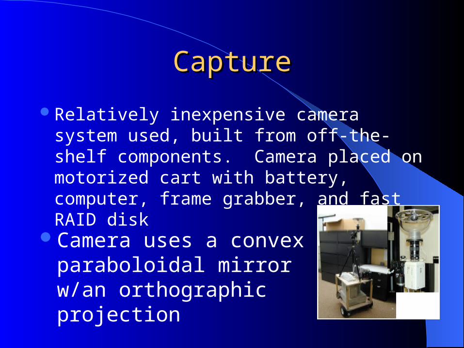
Relatively inexpensive camera system used, built from off-the-shelf components. Camera placed on motorized cart with battery, computer, frame grabber, and fast RAID disk
Camera uses a convex paraboloidal mirror w/an orthographic projection

Camera Pose EstimationCamera Pose EstimationCalibration scheme developed by Aliaga and
Carlbom that uses beacons for calibrationIn 2 corners of a region, beacons are placed.Before recording, user initializes pose
estimation by identifying the projections of the beacons in the first captured image
As camera moves, beacon is tracked and, using triangulation, derives camera position and orientation

ReconstructionReconstruction
Given a set of image loops, create novel planar views of environment from arbitrary viewpoints inside a loop
Combine pixels from omnidirectional images in the forward-looking view frustum with pixels in the omnidirectional images in the rear-looking frustum

ReconstructionReconstruction
New view created via column-by-column reconstruction of pixels from the omnidirectional images
If viewing direction for a column intersects the COP of 2 complimentary omnidirectional images, then that direction maps directly to radial lines in the images.

ReconstructionReconstruction
Corresponding segments of each radial line warped to the column in reconstructed image
Geometry of omnidirectional camera must be considered
Using similar triangles…

ReconstructionReconstruction
Because pixels from the image behind the viewpoint are generally stretched during the warp, pixels are drawn using fixed sized splats
Vertical disocclusions are filled in using longer than expected splats
Usually, viewing direction will not intersect exactly with COP of an omnidirectional image
Radial is generated then by blending 2 parallel radials

ReconstructionReconstruction
Difficult to reliably identify corresponding features in the radial lines from omnidirectional images on opposite sides of a loop
Temporal coherence of the entire image loop is used to identify the required features
Start with an arbitrary omni image, track features all the way around the loop

OptimizationOptimization
In ideal conditions, radial lines differ only by a radial displacement and should be easy to recover
In practice, feature tracking and camera pose estimation introduce errors into mapping

Optimization:Optimization: Rotational Correction Rotational Correction
This optimization accounts for incorrect pairing of radial lines
Features should move along same set of circles
Error represented by sum of squares of distances between corresponding features
Errors reduced by searching for better aligned rotations
Optimization:Optimization:Column CorrelationColumn Correlation
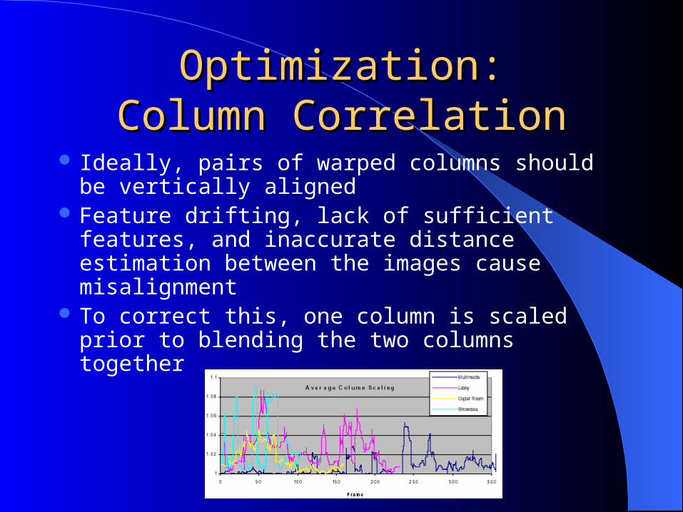
Ideally, pairs of warped columns should be vertically aligned
Feature drifting, lack of sufficient features, and inaccurate distance estimation between the images cause misalignment
To correct this, one column is scaled prior to blending the two columns together
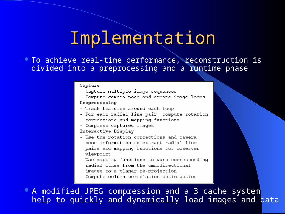
ImplementationImplementation To achieve real-time performance, reconstruction is divided into a
preprocessing and a runtime phase
A modified JPEG compression and a 3 cache system help to quickly and dynamically load images and data

ResultsResults
Reconstruction time varies slightly depending on # of features per column
Reconstructions of 320x160 and 640x320 pixels take between 5 to 10 frames/sec with a pixel splat of 1x4 pixels
Maximum capture time for the four environments recorded was 25 minutes

ResultsResults
Top image: Reconstructed using described method for viewpoint near middle of a loop
Bottom image: Planar re-projection of an image captured from approximately the same viewpoint

ResultsResults
Example reconstructions for viewpoints near the middle of image loops

ResultsResults
Environmental statistics:

That’s it!That’s it!
Questions?