power flow analysis for grid connected dgs and …ijitech.org/uploads/421365ijit15176-264.pdf ·...
TRANSCRIPT
WWW.IJITECH.ORG
ISSN 2321-8665
Vol.05,Issue.07,
July-2017,
Pages:1297-1301
Copyright @ 2017 IJIT. All rights reserved.
Power Flow Analysis for Grid Connected DGs and Battery Based
Multi-Input Transformer Coupled Bidirectional DC-DC Converter U. GAYATHRI
1, J. YUGANDHAR
2
1PG Scholar, Dept of EEE, Siddharth Institute of Engineering and Technology, Puttor, AP, India,
Email: [email protected]. 2Associate Professor, Dept of EEE, Siddharth Institute of Engineering and Technology, Puttor, AP, India,
Email: [email protected].
Abstract: In this project, a control strategy for power flow
management of a grid-connected hybrid PV-wind-battery
based system with an efficient multi-input transformer
coupled bidirectional dc-dc converter is presented. The aim of
our project is to satisfy the load demand, manage the power
flow from different sources, inject surplus power into the grid
and charge the battery from grid as and when required. A
transformer coupled boost half-bridge converter is used to
harness power from wind, while bidirectional buck-boost
converter is used to harness power from PV along with
battery charging/discharging control. A single-phase full-
bridge bidirectional converter is used for feeding ac loads and
interaction with grid. The proposed converter architecture has
reduced number of power conversion phases with less
component count, and reduced losses compared to existing
grid-connected hybrid systems. Then we are going to test the
single phase multilevel converter to feed ac loads and
interaction with grid.
Keywords: Photovoltaic (PV), Multi-Input Converter (MIC),
Wind, Battery.
I. INTRODUCTION
Fast consumption of fossil fuel holds, results in expanding
vitality request and concerns over environmental change
persuade control power generation from renewable energy
sources. solar based photovoltaic (PV) and wind have risen as
well known vitality sources due to their eco-friendly nature
and cost adequacy. Nonetheless, these sources are irregular in
nature. Consequently, it is a test to supply steady and
consistent power utilizing these sources. This can be tended to
by proficiently coordinating with energy storage components.
The interesting correlative conduct of sun powered insulation
and wind speed pattern combined has led to the exploration
on their combination bringing about the hybrid PV-wind
systems. For accomplishing the reconciliation of numerous
renewable sources, the customary approach includes utilizing
devoted single-input converters one for each source, which
are connected with a typical dc-link. Be that as it may, these
converters are not successfully used, because of the
discontinuous way of the renewable sources. Moreover, there
are numerous power transformation phases which decrease
the proficiency of the system. Hybrid PV-wind based system
of power and their interfaces with the power network are the
imperative research territories. Proposed multi-input half
breed PV-wind control generation system which has a
buck/buck-help combined multi-input dc-dc converter and a
full-bridge ac inverter.
This system is essentially centered around enhancing the
dc-interface voltage direction. The utilization of multi-input
converter (MIC) for hybrid control systems is pulling in
expanding consideration on account of decreased part
number, upgraded control thickness, smallness and
concentrated control. Because of these favorable conditions,
numerous topologies are proposed and they can be
characterized into three gatherings, non-detached, completely
segregated and halfway disengaged multi-port topologies. All
the state of the art on converter topologies presented so far
can oblige just a single renewable source and one energy
storage element. Though, the proposed topology is fit for
interfacing two renewable sources and a energy storage
element. Consequently, it is more solid as two distinct sorts of
renewable sources like PV and wind are utilized either
separately or at the same time without increment in the
segment tally contrasted with the existing state edge
topologies. The proposed system has two renewable power
sources, load, lattice and battery. Subsequently, a power flow
management system is basic to adjust the power flow among
every one of these sources. The primary goals of this system
are as per the following:
1. To investigate a multi-object control scheme for optimal
charging of the battery utilizing numerous sources.
2. Supplying un-interruptible energy to loads.
3. Ensuring departure of surplus power from renewable
sources to the network, and charging the battery from
system as and when required.
The network connected half breed PV-wind-battery based
system for family unit applications which can work either in
remains solitary or grid connected mode. This system is
reasonable for family unit applications, where an ease, basic
and reduced topology equipped for independent operation is
attractive. The center of the proposed system is the multi
input transformer coupled bidirectional dc-dc converter that
U. GAYATHRI, J. YUGANDHAR
International Journal of Innovative Technologies
Volume.05, Issue No.07, July-2017, Pages: 1297-1301
interconnects different power sources and the capacity
component.
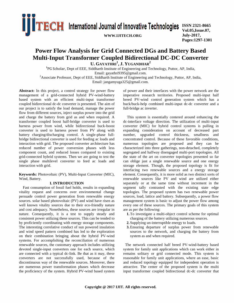
II. PROPOSED CONVERTER CONFIGURATION
The proposed converter comprises of a transformer coupled
boost double half-bridge bidirectional converter fused with
bidirectional buck-boost converter and a solitary phase full-
bridge inverter. The proposed converter has decreased
number of power transformation phases with less part check
and high productivity contrasted with the existing grid
connected plans. The topology is straightforward and needs
just six power switches. The schematic graph of the converter
is delineated in Fig.1. The boost double half-bridge converter
has two dc-interfaces on both sides of the high recurrence
transformer. Controlling the voltage of one of the dc-link,
guarantees controlling the voltage of the other. This makes
the control procedure basic. Besides, extra converters can be
incorporated with any of the two dc-links. A bidirectional
buck-help dc-dc converter is coordinated with the essential
side dc-connection and single-phase full scaffold bidirectional
converter is connected with the dc- connection of the
auxiliary side. The contribution of the half-bridge converter is
designed by associating the PV exhibit in arrangement with
the battery, accordingly incorporating an inherent boosting
phase for the scheme. The boosting capacity is further
improved by a high frequency step-up transformer.
Fig 1. Proposed converter configuration.
The transformer likewise guarantees galvanic segregation
to the load from the sources and the battery. Bidirectional
buck help converter is utilized to bridle control from PV
alongside battery charging/releasing control. The one of a
kind element of this converter is that MPP following, battery
charge control and voltage boosting are refined through a
solitary converter. Transformer coupled boost half-bridge
converter is utilized for harnessing power from wind and a
solitary phase full-bridge bidirectional converter is utilized for
sustaining air conditioning burdens and association with
system. The proposed converter has diminished number of
force change phases with less segment tally and high
proficiency contrasted with the current network connected
converters. The power flow of wind source is controlled
through a unidirectional boost half-bridge converter. For
acquiring MPP successfully, smooth variety in source current
is required which can be gotten utilizing an inductor. In the
proposed topology, an inductor is put in arrangement with the
wind source which guarantees constant current and
accordingly this inductor current can be utilized for keeping
up MPP current. During the ON time of T 3, the primary
voltage VP = −VC1.The secondary voltage VS = nVp =
−nVC1 = −VC3, or VC3 = nVC1 and voltage across primary
inductor Lw is Vw. When T 3 is turned OFF and T 4 turned
ON, the primary voltage VP = VC2. Secondary voltage VS =
nVp = nVC2 = VC4 and voltage across primary inductor Lw
is Vw − (VC1 +VC2). It can be proved that
.
The capacitor voltages are considered constant in steady
state and they settle at VC3 = nVC1, VC4 = nVC2. Hence the
output voltage is given by
(1)
In this manner, the yield voltage of the auxiliary side dc-
bridgeion is an element of the obligation cycle of the essential
side converter and turns proportion of transformer.
In the proposed design as appeared in Fig2(a), a bidirectional
buck-support converter is utilized for MPP following of PV
exhibit and battery charging/releasing control. Promote, this
bidirectional buck-support converter charges/releases the
capacitor bank C1-C2 of transformer coupled half-bridge help
converter in view of the load request. The half-bridge help
converter extricates vitality from the twist source to the
capacitor bank C1-C2. Amid battery charging mode, when
switch T 1 is ON, the vitality is put away in the inductor L. At
the point when switch T 1 is killed and T 2 is turned ON,
vitality put away in L is exchanged to the battery. On the off
chance that the battery releasing current is more than the PV
current, inductor current gets to be distinctly negative. Here,
the stored energy in the inductor increases when T 2 is turned
on and decreases when T 1 is turned on. It can be proved
that
. The output voltage of the transformer
coupled boost half-bridge converter is given by,
(2)
This voltage is n times of primary side dc-link voltage. The
primary side dc-link voltage can be controlled by half-bridge
boost converter or by bidirectional buck-boost converter. The
relationship between the average value of inductor, PV and
battery current over a switching cycle is given by IL = Ib +
Ipv. It is evident that, Ib and Ipv can be controlled by
controlling IL. Therefore, the MPP operation is assured by
controlling IL while maintaining proper battery charge level.
IL is used as inner loop control parameter for faster dynamic
response while for outer loop, capacitor voltage across PV
source is used for ensuring MPP voltage. An incremental
conductance method is used for MPPT.
A. Limitations and Design issues
The output voltage Vdc of transformer coupled boost dual
half-bridge converter, depends on MPP voltage of PV array
VPV mpp, the battery voltage Vb and the transformer turns
ratio n.
III. PROPOSED CONTROL SCHEME FOR POWER
FLOW MANAGEMENT
A lattice connected half and half PV-wind-battery based
system comprising of four power sources (grid, PV, wind
Power Flow Analysis for Grid Connected DGs and Battery Based Multi-Input Transformer Coupled Bidirectional DC-DC Converter
International Journal of Innovative Technologies
Volume.05, Issue No.07, July-2017, Pages: 1297-1301
source and battery) and three power sinks (network, battery
and load), requires a control conspire for power flow
management to adjust the power flow among these sources.
The control reasoning for power flow management of the
multi-source system is produced in view of the power adjust
standard. In the remain solitary case, PV and wind source
produce their comparing MPP power and load takes the
required power. For this situation, the power adjust is
accomplished by charging the battery until it achieves its
greatest charging current farthest point Ibmax. After
achieving this farthest point, to guarantee control adjust, one
of the sources or both need to go astray from their MPP
control in view of the load request. In the lattice connected
system both the sources dependably work at their MPP.
Without both the sources, the power is attracted from the
lattice to charge the battery as and when required. The
condition for the power management of the system is given
by:
(3)
The peak value of the output voltage for a single-phase full
bridge inverter is,
(4)
and the dc-link voltage is,
Vdc = n (Vpv + Vb) (5)
Hence, by substituting for Vdc in (4), gives,
(6)
In the boost half-bridge converter,
(7)
Now substituting Vw and Vg in (3),
(8)
After simplification,
(9)
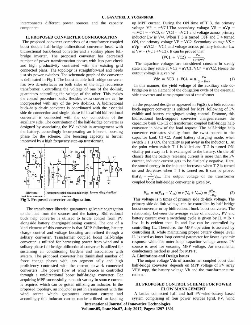
Fig 2. Controlling for circuit shown in fig.1.
from the above conditions it is obvious that, if there is an
adjustment in power decreases from either PV or wind source,
the battery current can be directed by controlling the lattice
current Ig. Thus, the control of a solitary phase full-bridge
bidirectional converter relies on upon accessibility of
network, power from PV and wind sources and battery charge
status. Its control procedure is delineated utilizing Fig. 3. To
guarantee the supply of continuous energy to basic burdens,
need is given to charge the batteries. In the wake of achieving
the most extreme battery charging current point of
confinement Ibmax, the surplus power from renewable
sources is bolstered to the grid. Without these sources, battery
is charged from the system.
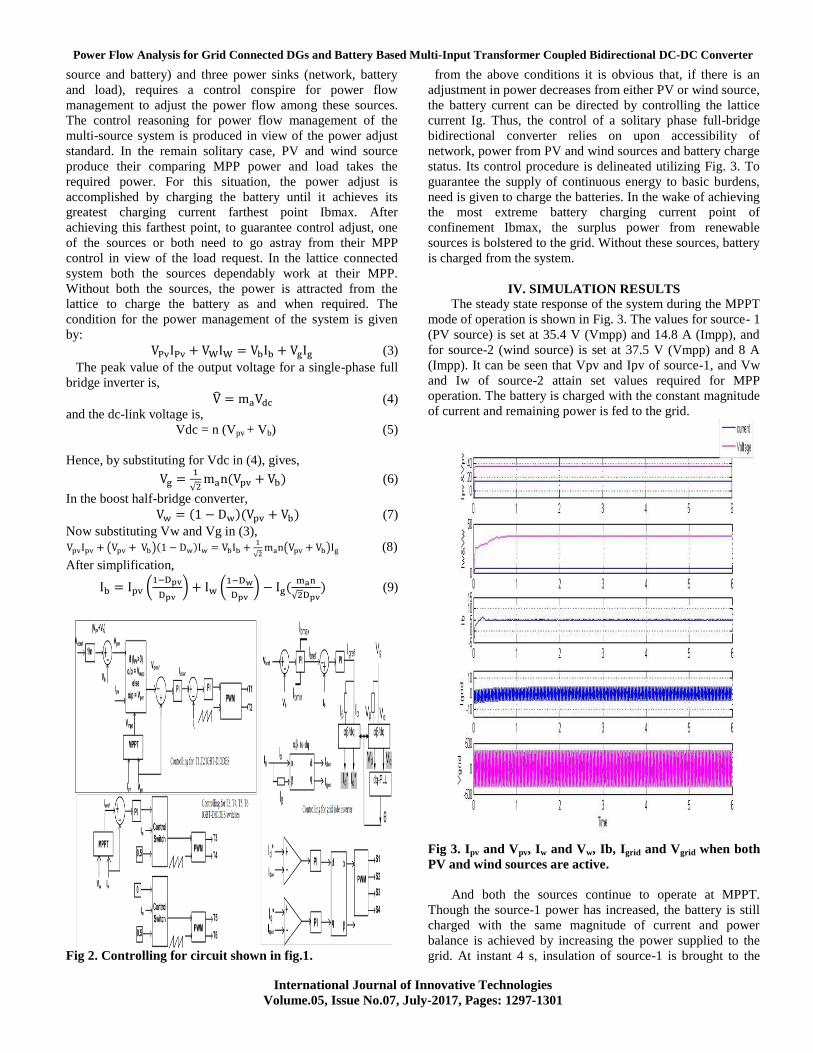
IV. SIMULATION RESULTS
The steady state response of the system during the MPPT
mode of operation is shown in Fig. 3. The values for source- 1
(PV source) is set at 35.4 V (Vmpp) and 14.8 A (Impp), and
for source-2 (wind source) is set at 37.5 V (Vmpp) and 8 A
(Impp). It can be seen that Vpv and Ipv of source-1, and Vw
and Iw of source-2 attain set values required for MPP
operation. The battery is charged with the constant magnitude
of current and remaining power is fed to the grid.
Fig 3. Ipv and Vpv, Iw and Vw, Ib, Igrid and Vgrid when both
PV and wind sources are active.
And both the sources continue to operate at MPPT.
Though the source-1 power has increased, the battery is still
charged with the same magnitude of current and power
balance is achieved by increasing the power supplied to the
grid. At instant 4 s, insulation of source-1 is brought to the
U. GAYATHRI, J. YUGANDHAR
International Journal of Innovative Technologies
Volume.05, Issue No.07, July-2017, Pages: 1297-1301
same level as before 2s. The power supplied by source-1
decreases. Battery continues to get charged at the same
magnitude of current, and power injected into the grid
decreases. The same results are obtained for step changes in
source-2 wind speed level.
Fig 4. Ipv and Vpv, Iw and Vw, Ib, Igrid and Vgrid When
wind sources increases.
Fig 5. Ipv and Vpv, Iw and Vw, Ib, Igrid and Vgrid When PV
sources increases.
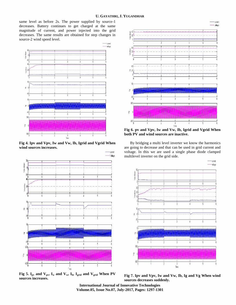
Fig 6. pv and Vpv, Iw and Vw, Ib, Igrid and Vgrid When
both PV and wind sources are inactive.
By bridging a multi level inverter we know the harmonics
are going to decrease and that can be used in grid current and
voltage. In this we are used a single phase diode clamped
multilevel inverter on the grid side.
Fig 7. Ipv and Vpv, Iw and Vw, Ib, Ig and Vg When wind
sources decreases suddenly.
Power Flow Analysis for Grid Connected DGs and Battery Based Multi-Input Transformer Coupled Bidirectional DC-DC Converter
International Journal of Innovative Technologies
Volume.05, Issue No.07, July-2017, Pages: 1297-1301
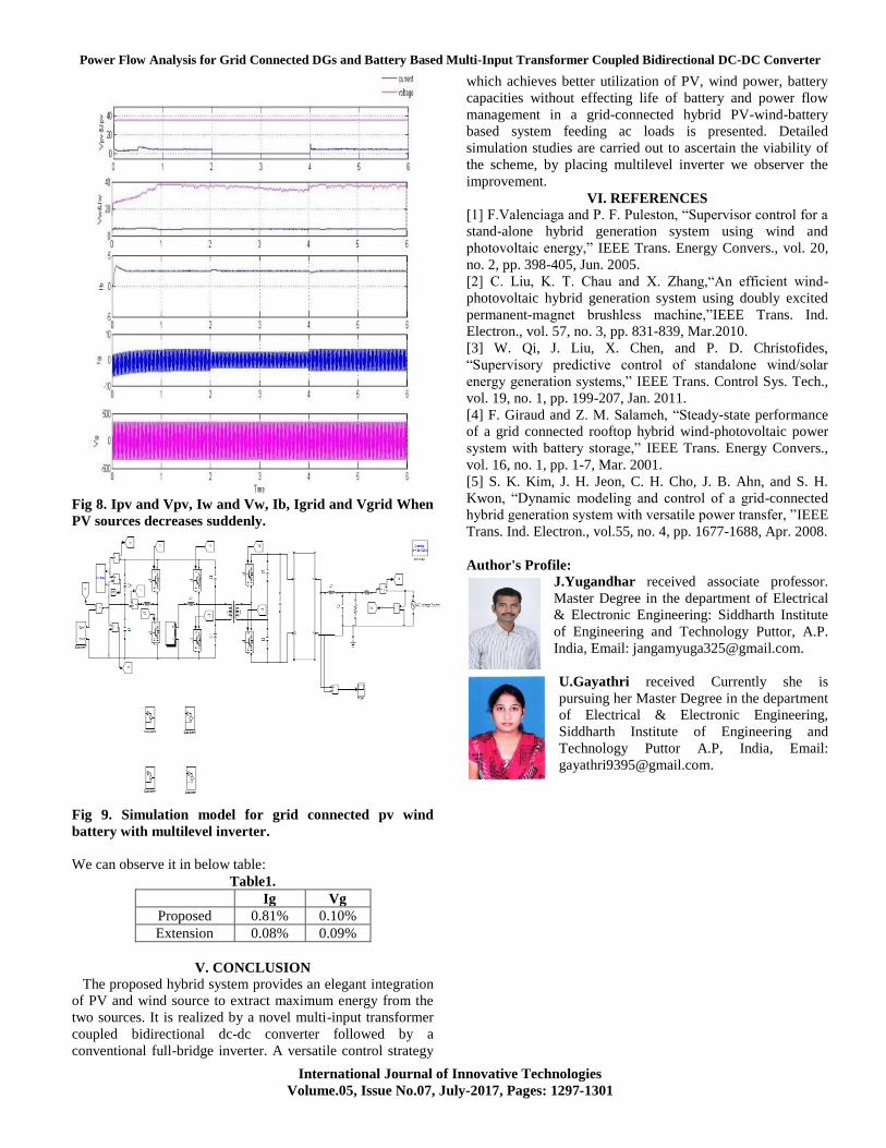
Fig 8. Ipv and Vpv, Iw and Vw, Ib, Igrid and Vgrid When
PV sources decreases suddenly.
Fig 9. Simulation model for grid connected pv wind
battery with multilevel inverter.
We can observe it in below table:
Table1.
Ig Vg
Proposed 0.81% 0.10%
Extension 0.08% 0.09%
V. CONCLUSION
The proposed hybrid system provides an elegant integration
of PV and wind source to extract maximum energy from the
two sources. It is realized by a novel multi-input transformer
coupled bidirectional dc-dc converter followed by a
conventional full-bridge inverter. A versatile control strategy
which achieves better utilization of PV, wind power, battery
capacities without effecting life of battery and power flow
management in a grid-connected hybrid PV-wind-battery
based system feeding ac loads is presented. Detailed
simulation studies are carried out to ascertain the viability of
the scheme, by placing multilevel inverter we observer the
improvement.
VI. REFERENCES
[1] F.Valenciaga and P. F. Puleston, “Supervisor control for a
stand-alone hybrid generation system using wind and
photovoltaic energy,” IEEE Trans. Energy Convers., vol. 20,
no. 2, pp. 398-405, Jun. 2005.
[2] C. Liu, K. T. Chau and X. Zhang,“An efficient wind-
photovoltaic hybrid generation system using doubly excited
permanent-magnet brushless machine,”IEEE Trans. Ind.
Electron., vol. 57, no. 3, pp. 831-839, Mar.2010.
[3] W. Qi, J. Liu, X. Chen, and P. D. Christofides,
“Supervisory predictive control of standalone wind/solar
energy generation systems,” IEEE Trans. Control Sys. Tech.,
vol. 19, no. 1, pp. 199-207, Jan. 2011.
[4] F. Giraud and Z. M. Salameh, “Steady-state performance
of a grid connected rooftop hybrid wind-photovoltaic power
system with battery storage,” IEEE Trans. Energy Convers.,
vol. 16, no. 1, pp. 1-7, Mar. 2001.
[5] S. K. Kim, J. H. Jeon, C. H. Cho, J. B. Ahn, and S. H.
Kwon, “Dynamic modeling and control of a grid-connected
hybrid generation system with versatile power transfer, ”IEEE
Trans. Ind. Electron., vol.55, no. 4, pp. 1677-1688, Apr. 2008.
Author's Profile: J.Yugandhar received associate professor.
Master Degree in the department of Electrical
& Electronic Engineering: Siddharth Institute
of Engineering and Technology Puttor, A.P.
India, Email: [email protected].
U.Gayathri received Currently she is
pursuing her Master Degree in the department
of Electrical & Electronic Engineering,
Siddharth Institute of Engineering and
Technology Puttor A.P, India, Email: