power generation - ivpluss.ee · fpt power generation 6 fpt power generation 7 superior technology...
TRANSCRIPT

POWERGENERATION
Our efficiency.Your edge.
POWERGENERATION
Our efficiency.Your edge.
2 3Power Generation Power GenerationFPT FPT IndexIndex
Index
Introduction
Power Generation Line-Up
G-Drive EnginesThe S8000 SeriesThe F5 SeriesThe NEF SeriesThe Cursor Series
Generator SetsOpen GensetsSoundproofed Gensets
HI-eSCRTIER4 Final
6
10
20
22
30
40
52
62
64
72
86
88
5FPTFPT 4 Power Generation IntroductionIntroductionPower Generation
THE ENERGY OFINNOVATION

6 7Power Generation Power GenerationFPT FPT
Superior Technology & Outstanding Advantages
IntroductionIntroduction
PerformanceExcellent transient load response. High performance guaranteed in all conditions. High engine power density.
Respect for the EnvironmentCompliance with the most stringent Emissions legislations. Low noise levels.
Running Costs ReductionLow oil and fuel consumption. Best in class maintenance intervals. Low running costs in continuous operating power.
FlexibilityAvailability of a wide range of options to create tailor-made products. Compact engine layout. Availability of cold starting accessories.
You need power, delivered quickly and reliably. FPT Industrial is there to answer your needs. Our new range of state-of-the-art engines covers all power generation applications.
Sustainability drives product develop-ment. As the standards for diesel engines grow ever more stringent, a constant decrease in emissions becomes a key benchmark for improvement.
To fulfill market requirements, FPT Industrial has developed different engine ranges. All comply with the most demanding standards. Our products have functional layouts, hi-tech contents and carefully selected, top-quality components.
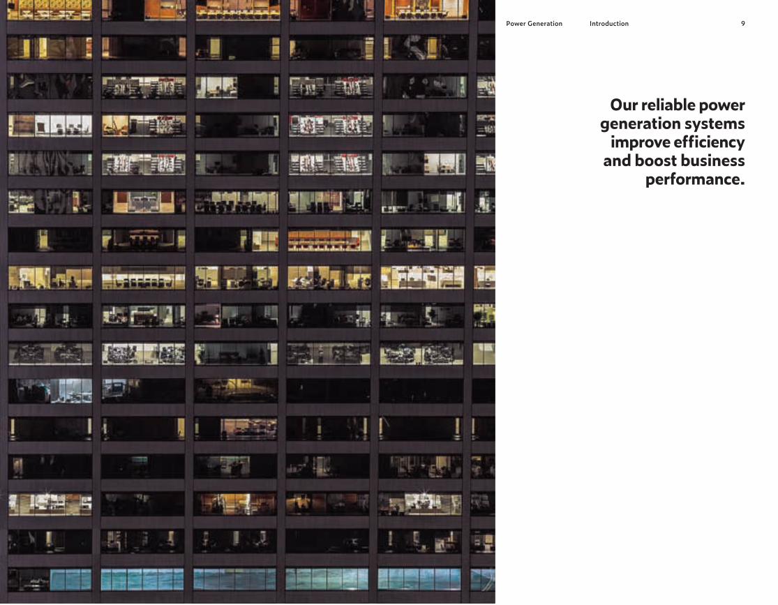
9Power Generation Introduction
Our reliable power generation systems
improve efficiency and boost business
performance.

1110 Power Generation PG Line-UpPG Line-UpPower Generation
POWER GENERATION LINE-UP
FPTFPT

13FPT FPT PG Line-UpPG Line-Up G-Drive Engines12G-Drive Engines
Legend Arrangement L In line Air Intake NA Naturally Aspirated TAA Turbocharged Aftercooler TC Turbocharged
Exhaust System I-EGR Internal Exhaust Gas Recirculation DOC Diesel Oxidation Catalyst SCR Selective Catalytic Reduction CUC Clean-up Catalyst
Injection System M Mechanical ECR Electronic Common Rail EUI Electronic Unit Injector
kVA kiloVolt Ampere calculations based on a 0.8 power factor 1. Preliminary data UR Unregulated UR1 Previously EU Stage II 2 Complies to TA Luft (1986) regulations 3 TÜV measured based on TA-Luft standards
1500 rpm / 1800 rpm switchable engine
Not Switchable Engine ** Fan absorption: 1%-6%
Model
Cyli
nder
Arra
ngemen
t Air
Int
ake
Exha
ust Syst
em
Inject
ion
Syst
em
Disp
lace
men
t Lite
rs
Emis
sion
s
S8000AM13 N45AM1A3 N45AM2 N45SM1A3 N45SM3 N45TM2A3 N45TM33 N67SM1 N67TM2A3 N67TM3A3 N67TM4 N67TE2A2 N67TM7 N67TE8W3 CURSOR87TE43 CURSOR13TE2A3 CURSOR13TE3A3 CURSOR13TE6W CURSOR13TE7W CURSOR16TE1W3
3L/NA 4L/NA 4L/NA 4L/TC 4L/TC 4L/TAA 4L/TAA 6L/TC 6L/TAA 6L/TAA 6L/TAA 6L/TAA 6L/TAA 6L/TAA 6L/TAA 6L/TAA 6L/TAA 6L/TAA 6L/TAA 6L/TAA
M M M M M M M M M M M ECR M ECR ECR EUI EUI ECR ECR ECR
2,9
4,5
4,5
4,5
4,5
4,5
4,5
6,7
6,7
6,7
6,7
6,7
6,7
6,7
8,7
12,9
12,9
12,9
12,9
15,9
UR UR1 UR UR1 UR UR1 UR UR UR1 UR1
UR UR1 UR UR UR UR1 UR1 UR UR UR
50 Hz / 1500 rpm 60 Hz / 1800 rpm
Typi
cal Ge
nera
tor eff.
1500/180
0 rp
m Sw
itch
able
Stand-by Power
Prime Power
Stand-by Power
Prime Power
kWm (net)
kWe kVA kWm (net)
kWe kVA kWm (net)
kWe kVA kWm (net)
kWe kVA
31
46
50
59
81
96
118
121
126
152
165
193
195
238
299
330
387
414
459
557
27
40
44
54
74
88
109
111
116
140
152
179
181
221
278
308
364
395
438
529
34
51
55
67
92
110
136
139
145
175
190
224
227
277
348
384
455
494
547
661
28
42
45
53
73
88
107
110
114
138
150
175
177
216
275
300
352
374
425
505
25
37
40
48
66
81
98
101
105
127
138
163
165
201
256
280
331
357
405
480
31
46
50
60
83
101
123
127
131
159
173
203
206
251
320
350
414
446
507
600
34 - -
65
87
107
122
138
141
165 -
215
195
253
333
360
398
454
474
578
30 - -
59
79
98
112
127
130
152 -
200
181
235
310
336
374
433
452
549
37 - -
74
99
123
140
159
162
190 -
250
227
294
387
419
468
541
565
686
31 - -
59
79
98
111
125
128
149 -
195
177
230
306
327
360
400
428
523
27 - -
54
72
90
102
115
118
137 -
181
165
214
285
305
338
382
408
497
34 - -
67
90
113
128
144
147
171 -
227
206
267
356
381
423
477
510
621
88%
88%
88%
91%
91%
92%
92%
92%
92%
92%
92%
93%
93%
93%
93%
93%
94%
95%
95%
95%
G-Drive EnginesNOT REGULATED EMISSIONS
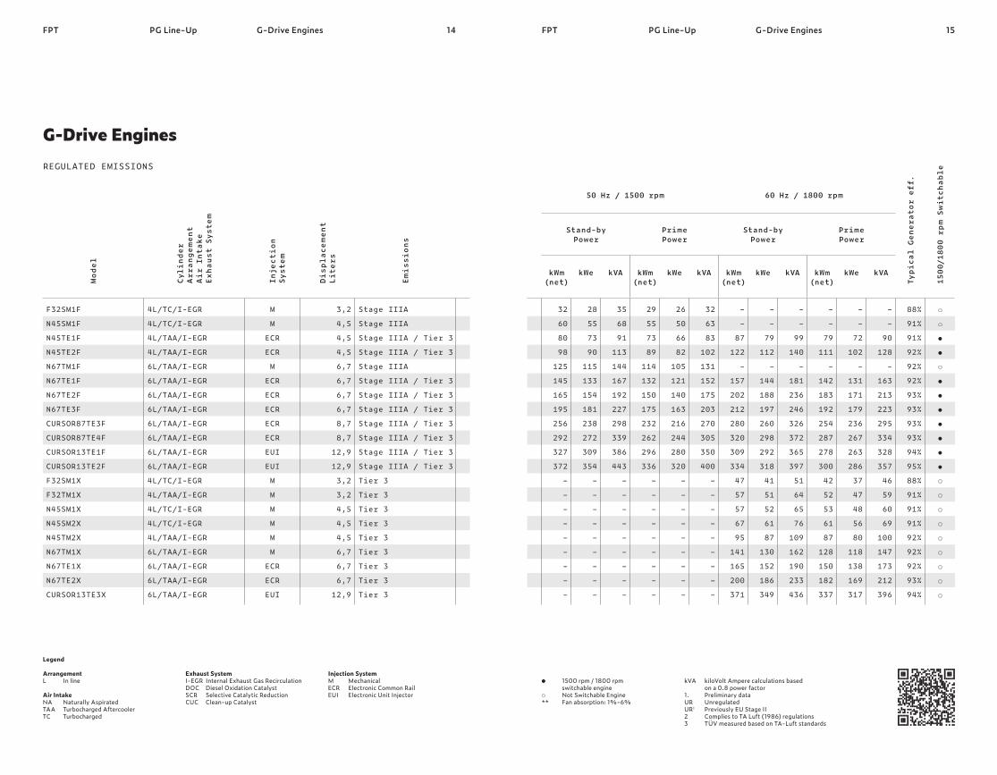
14 15FPT FPT PG Line-UpPG Line-Up G-Drive EnginesG-Drive Engines
Legend Arrangement L In line Air Intake NA Naturally Aspirated TAA Turbocharged Aftercooler TC Turbocharged
Exhaust System I-EGR Internal Exhaust Gas Recirculation DOC Diesel Oxidation Catalyst SCR Selective Catalytic Reduction CUC Clean-up Catalyst
Injection System M Mechanical ECR Electronic Common Rail EUI Electronic Unit Injector
kVA kiloVolt Ampere calculations based on a 0.8 power factor 1. Preliminary data UR Unregulated UR1 Previously EU Stage II 2 Complies to TA Luft (1986) regulations 3 TÜV measured based on TA-Luft standards
1500 rpm / 1800 rpm switchable engine
Not Switchable Engine ** Fan absorption: 1%-6%
Model
Cyli
nder
Arra
ngemen
t Air
Int
ake
Exha
ust Syst
em
Inject
ion
Syst
em
Disp
lace
men
t Lite
rs
Emis
sion
s
F32SM1F N45SM1F N45TE1F N45TE2F N67TM1F N67TE1F N67TE2F N67TE3F CURSOR87TE3F CURSOR87TE4F CURSOR13TE1F CURSOR13TE2F F32SM1X F32TM1X N45SM1X N45SM2X N45TM2X N67TM1X N67TE1X N67TE2X CURSOR13TE3X
4L/TC/I-EGR 4L/TC/I-EGR 4L/TAA/I-EGR 4L/TAA/I-EGR 6L/TAA/I-EGR 6L/TAA/I-EGR 6L/TAA/I-EGR 6L/TAA/I-EGR 6L/TAA/I-EGR 6L/TAA/I-EGR 6L/TAA/I-EGR 6L/TAA/I-EGR 4L/TC/I-EGR 4L/TAA/I-EGR 4L/TC/I-EGR 4L/TC/I-EGR 4L/TAA/I-EGR 6L/TAA/I-EGR 6L/TAA/I-EGR 6L/TAA/I-EGR 6L/TAA/I-EGR
M M ECR ECR M ECR ECR ECR ECR ECR EUI EUI M M M M M M ECR ECR EUI
3,2
4,5
4,5
4,5
6,7
6,7
6,7
6,7
8,7
8,7
12,9
12,9
3,2
3,2
4,5
4,5
4,5
6,7
6,7
6,7
12,9
Stage IIIA Stage IIIA Stage IIIA / Tier 3 Stage IIIA / Tier 3 Stage IIIA Stage IIIA / Tier 3 Stage IIIA / Tier 3 Stage IIIA / Tier 3 Stage IIIA / Tier 3 Stage IIIA / Tier 3 Stage IIIA / Tier 3 Stage IIIA / Tier 3 Tier 3 Tier 3 Tier 3 Tier 3 Tier 3 Tier 3 Tier 3 Tier 3 Tier 3
50 Hz / 1500 rpm 60 Hz / 1800 rpm
Typi
cal Ge
nera
tor eff.
1500/180
0 rp
m Sw
itch
able
Stand-by Power
Prime Power
Stand-by Power
Prime Power
kWm (net)
kWe kVA kWm (net)
kWe kVA kWm (net)
kWe kVA kWm (net)
kWe kVA
32
60
80
98
125
145
165
195
256
292
327
372 – – – – – – – – –
28
55
73
90
115
133
154
181
238
272
309
354 – – – – – – – – –
35
68
91
113
144
167
192
227
298
339
386
443 – – – – – – – – –
29
55
73
89
114
132
150
175
232
262
296
336 – – – – – – – – –
26
50
66
82
105
121
140
163
216
244
280
320 – – – – – – – – –
32
63
83
102
131
152
175
203
270
305
350
400 – – – – – – – – –
– –
87
122 –
157
202
212
280
320
309
334
47
57
57
67
95
141
165
200
371
– –
79
112 –
144
188
197
260
298
292
318
41
51
52
61
87
130
152
186
349
– –
99
140 –
181
236
246
326
372
365
397
51
64
65
76
109
162
190
233
436
– –
79
111 –
142
183
192
254
287
278
300
42
52
53
61
87
128
150
182
337
– –
72
102 –
131
171
179
236
267
263
286
37
47
48
56
80
118
138
169
317
– –
90
128 –
163
213
223
295
334
328
357
46
59
60
69
100
147
173
212
396
88%
91%
91%
92%
92%
92%
93%
93%
93%
93%
94%
95%
88%
91%
91%
91%
92%
92%
92%
93%
94%
REGULATED EMISSIONS
G-Drive Engines

16 17FPT FPT PG Line-UpPG Line-Up Bare EnginesBare Engines
Legend Arrangement L In line Air Intake NA Naturally Aspirated TAA Turbocharged Aftercooler TC Turbocharged
Exhaust System I-EGR Internal Exhaust Gas Recirculation DOC Diesel Oxidation Catalyst SCR Selective Catalytic Reduction CUC Clean-up Catalyst
Injection System M Mechanical ECR Electronic Common Rail EUI Electronic Unit Injector
kVA kiloVolt Ampere calculations based on a 0.8 power factor 1. Preliminary data UR Unregulated UR1 Previously EU Stage II 2 Complies to TA Luft (1986) regulations 3 TÜV measured based on TA-Luft standards
1500 rpm / 1800 rpm switchable engine
Not Switchable Engine ** Fan absorption: 1%-6%
50 Hz / 1500 rpm 60 Hz / 1800 rpm
Typi
cal Ge
nera
tor eff.
1500/180
0 rp
m Sw
itch
able
Stand-by Power
Prime Power
Stand-by Power
Prime Power
kWm (gross)
kWe** kVA** kWm (gross)
kWe** kVA** kWm (gross)
kWe** kVA** kWm (gross)
kWe** kVA**
– – – – – – – – – – – – –
– – – – – – – – – – – – –
– – – – – – – – – – – – –
– – – – – – – – – – – – –
– – – – – – – – – – – – –
– – – – – – – – – – – – –
85
126
145
167
195
223
260
282
309
330
353
380
424
78
116
129
149
175
200
233
253
281
301
324
350
391
97
145
161
186
219
251
291
316
351
376
404
438
488
77
115
132
152
177
203
236
256
281
300
321
345
385
70
106
116
135
158
182
210
229
255
273
294
318
355
88
132
145
169
198
227
263
286
318
341
368
397
443
93%
93%
93%
93%
93%
93%
93%
93%
94%
94%
94%
95%
95%
REGULATED EMISSIONS
Model
Cyli
nder
Arra
ngemen
t Air
Int
ake
Exha
ust Syst
em
Inject
ion
Syst
em
Disp
lace
men
t Lite
rs
Emis
sion
s
N45ENTZW681 N45ENTZW69 N67ENTZW611 N67ENTZW621 N67ENTZW68 N67ENTZW69 CURSOR87ENTZW61 CURSOR87ENTZW62 CURSOR87ENTZW68 CURSOR87ENTZW69 CURSOR13ENTZW61 CURSOR13ENTZW68 CURSOR13ENTZW69
4L / TAA / DOC + SCR+CUC 4L / TAA / DOC + SCR+CUC 6L / TAA / DOC + SCR+CUC 6L / TAA / DOC + SCR+CUC 6L / TAA / DOC + SCR+CUC 6L / TAA / DOC + SCR+CUC 6L / TAA / DOC + SCR+CUC 6L / TAA / DOC + SCR+CUC 6L / TAA / DOC + SCR+CUC 6L / TAA / DOC + SCR+CUC 6L / TAA / DOC + SCR+CUC 6L / TAA / DOC + SCR+CUC 6L / TAA / DOC + SCR+CUC
ECR ECR ECR ECR ECR ECR ECR ECR ECR ECR ECR ECR ECR
4,5
4,5
6,7
6,7
6,7
6,7
8,7
8,7
8,7
8,7
12,9
12,9
12,9
Tier 4 Final Tier 4 Final Tier 4 Final Tier 4 Final Tier 4 Final Tier 4 Final Tier 4 Final Tier 4 Final Tier 4 Final Tier 4 Final Tier 4 Final Tier 4 Final Tier 4 Final
Bare Engines


2120 Power Generation G-Drive EnginesG-Drive EnginesPower Generation
G-DRIVE ENGINES
FPTFPT

22 23FPT FPT
Performance The new S8000 delivers 4-cylinder performance with the compactness and lightness of a 3-cylin-der engine.
Efficiency & Productivity Best-in-class load acceptance and fre-quency stability make S8000 the best choice for telecom applications.
Maintenance Best-in-class oil service intervals at 600 hours contribute to enhanced uptime (30% longer).
Compactness Low TCO, compact-ness and simplicity.
G-Drive EnginesG-Drive Engines S8000
THE S8000 SERIES
S8000
From 31 to 34 kWm

25FPT24FPT
S8000
Our S8000 G-Drive range cuts down complexity. It is ideal for remote loca-tions, bringing high power output at a lower cost of ownership. Engineered to FPT Industrial’s renowned reliability levels, the engine in this range also feature best-in-class maintenance intervals. It is been developed with customer needs in mind. It is designed for all emergency and prime power applications that do not require com- pliance with emissions regulations.
G-Drive Engines S8000

26 27FPT FPT G-Drive EnginesG-Drive Engines S8000
Legend Arrangement L In line
Air Intake NA Naturally Aspirated
Injection System M Mechanical
Model
Cyli
nder
Arra
ngemen
t Air
Int
ake
Exha
ust Syst
em
Inject
ion
Syst
em
Disp
lace
men
t Lite
rs
Emis
sion
s
S8000AM13 3L/NA M 2,9 UR
NOT REGULATED EMISSIONS
S8000
kVA kiloVolt Ampere calculations based on a 0.8 power factor UR Unregulated 3 TÜV measured based on TA-Luft standards
1500 rpm / 1800 rpm switchable engine
Not Switchable Engine
50 Hz / 1500 rpm 60 Hz / 1800 rpm
Typi
cal Ge
nera
tor eff.
1500/180
0 rp
m Sw
itch
able
Stand-by Power
Prime Power
Stand-by Power
Prime Power
kWm (net)
kWe kVA kWm (net)
kWe kVA kWm (net)
kWe kVA kWm (net)
kWe kVA
31 27 34 28 25 31 34 30 37 31 27 34 88%
Engine Specifications

28G-Drive EnginesFPT S8000 29G-Drive EnginesFPT S8000
Key Advantages
Class G2 of ISO 8528 stand-ard certification of excellent performance related to load acceptance. Based on simple and proven mechanical rotary pump, S8000 engine has a direct fuel injection system which is state-of-the-art for accu-rate fuel delivery. Compact 3 Cylinder in-line with big unit displacement and long stroke. Lean lay-out; starting tem-perature without auxiliaries down to -5°C (with heat greater down to -12°C). Tropicalized radiator deliv-ered as standard in order. S8000 engine is available in naturally aspirated version with cooling package rack mounted on engine (non fix on frame is required).
Optimum design in terms of mechanical clearances, pis-ton rings, engine oil system calculation and optimized engine structure to limit cyl-inder liners deformation. Integrated CCV (Closed Crankcase Ventilation) system and engine design oriented to high component integration. Possibility to switch from 1.500 rpm to 1.800 rpm (50Hz/60Hz).
100% Trantransient load response for any stand-by and prime application. Simple and easy to install solution pick-up free. Compact packaging and installation footprint. High performance guaran-teed in all conditions. High power density simple and easy to install solution.
Performance Mechanical Injection System with Electronic Governor Engine Design Specific Features
Air Handling
600h Oil Interval Change
Component Integration
Dual Speed Mode
Features Features Benefits Benefits
Reduced maintenance needs and operating cost. Leakage prevention. Product flexibility based on market request.

30 31FPT FPT
Performance Low operating costs and extremely easy maintenance com-bined with excel-lent transient load response.
Efficiency & Productivity Emission performance is achieved without external EGR, VGT or electronics.
Maintenance Top-class 600-hours oil change intervals.
Compactness Lean layout and high component integra-tion facilitate engine installation.
G-Drive EnginesG-Drive Engines F5
THE F5 SERIES
F5
From 32 to 57 kWm

33FPT32FPT PG Line-Up F5
F32 SM F32 TM
G-Drive Engines F5
Our F5 series, featuring customer oriented design, stands out for low operating costs. Single-side servicing means maintenance is extremely easy.
These benefits combine with excellent performance: the engines can be used for the most demanding missions, including with high engine inclination or in temperatures as low as -25 °C (-13 °F).

34 35FPT FPT G-Drive EnginesG-Drive Engines F5
Legend Arrangement L In line Air Intake TAA Turbocharged Aftercooler TC Turbocharged
Exhaust System I-EGR Internal Exhaust Gas Recirculation
Injection System M Mechanical
Model
Cyli
nder
Arra
ngemen
t Air
Int
ake
Exha
ust Syst
em
Inject
ion
Syst
em
Disp
lace
men
t Lite
rs
Emis
sion
s
F32SM1F F32SM1X F32TM1X
4L/TC/I-EGR 4L/TC/I-EGR 4L/TAA/I-EGR
M M M
3,2
3,2
3,2
Stage IIIA Tier 3 Tier 3
REGULATED EMISSIONS
F5
kVA kiloVolt Ampere calculations based on a 0.8 power factor
1500 rpm / 1800 rpm switchable engine
Not Switchable Engine ** Fan absorption: 1%-6%
50 Hz / 1500 rpm 60 Hz / 1800 rpm
Typi
cal Ge
nera
tor eff.
1500/180
0 rp
m Sw
itch
able
Stand-by Power
Prime Power
Stand-by Power
Prime Power
kWm (net)
kWe kVA kWm (net)
kWe kVA kWm (net)
kWe kVA kWm (net)
kWe kVA
32 –
28 –
35 –
29 – –
26 – –
32 – –
–
47
57
–
41
51
–
51
64
–
42
52
–
37
47
–
46
59
88%
88%
91%
Engine Specifications

36G-Drive EnginesFPT F5 37G-Drive EnginesFPT F5
Key Advantages
Class G2 of ISO 8528 stand-ard certification of excellent performance related to load acceptance. Based on simple and proven mechanical rotary pump, F5 engines have a direct fuel injection system which is state-of-the-art for accurate fuel delivery. Camshaft in crankcase, suspended oil pan, balancer counterweights incorporated in crankshaft webs. Lean layout; starting tem-perature without auxiliaries down to –10°C (with grid heater down to -25°C). F5 Series engines are availa-ble in naturally aspirated, turbocharged and turbo-charged with aftercooler versions, in order to reach the highest engine.
Optimum engine design in terms of mechanical clear-ances, piston rings, engine oil system calculation and optimized. Integrated CCV (Closed Crankcase Ventilation) system and engine design oriented to high component integration. One side (left) engine main-tenance layout and world-wide service network. Options for electronic speed governor; hot part guards, water jacket heater, alarm senders, oil drain systems, front radiator guard.
Excellent transient load response for several power generation applications. Simple and easy to install solution, consistent with standard and alternative fuels. Vibration & noise reduction. High performance guaran-teed in all conditions. High engine power density with the shortest load response time.
Reduced maintenance needs and operating cost. Leakage prevention. Quick service support and easy maintenance. Customer orientation and specific engine architecture based on application type.
Performance Mechanical Injection System Engine Design Specific Features Air Handling
600h Oil Interval Change Component Integration
Serviceability & Maintainability Option List
Features Features Benefits Benefits


40 41FPT FPT G-Drive EnginesG-Drive Engines The NEF Series
THE NEF SERIES
The NEF Series
Performance High thermodynam-ic performance and engine response make these engines the best choice.
Efficiency & Productivity Emission performance is achieved without external EGR, VGT or electronics systems.
Maintenance Extra-long oil change intervals (up to 800 hours with NEF me-chanical versions).
Compactness Compact size and high component integra-tion facilitate engine installation.
From 46 to 253 kWm

43FPT42FPT
N45 AM / SM N45 TM / TE
N67 SM / TM N67 TE
The NEF Series showcases FPT Industrial’s technological excellence.Developed to satisfy the most demanding requirements, the engines in this range stand out for reliability and reduced fuel consumption.
They are available with 4 or 6 cylinders, with a mechanical or electronic common-rail injection system.
G-Drive Engines The NEF Series G-Drive Engines The NEF Series
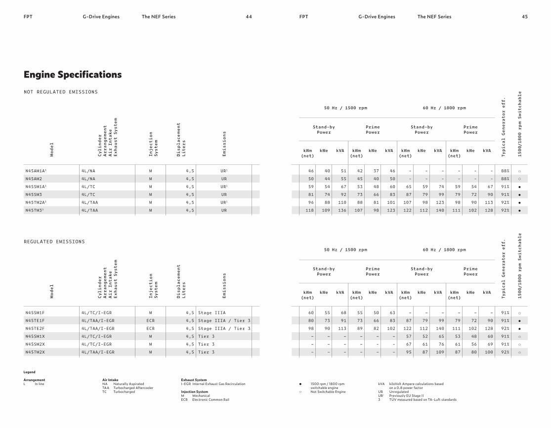
44 45FPT FPT G-Drive EnginesG-Drive Engines The NEF Series
Legend Arrangement L In line
Air Intake NA Naturally Aspirated TAA Turbocharged Aftercooler TC Turbocharged
Exhaust System I-EGR Internal Exhaust Gas Recirculation Injection System M Mechanical ECR Electronic Common Rail
Model
Cyli
nder
Arra
ngemen
t Air
Int
ake
Exha
ust Syst
em
Inject
ion
Syst
em
Disp
lace
men
t Lite
rs
Emis
sion
s
N45AM1A3 N45AM2 N45SM1A3 N45SM3 N45TM2A3 N45TM33
4L/NA 4L/NA 4L/TC 4L/TC 4L/TAA 4L/TAA
M M M M M M
4,5
4,5
4,5
4,5
4,5
4,5
UR1 UR UR1 UR UR1 UR
NOT REGULATED EMISSIONS
Model
Cyli
nder
Arra
ngemen
t Air
Int
ake
Exha
ust Syst
em
Inject
ion
Syst
em
Disp
lace
men
t Lite
rs
Emis
sions
N45SM1F N45TE1F N45TE2F N45SM1X N45SM2X N45TM2X
4L/TC/I-EGR 4L/TAA/I-EGR 4L/TAA/I-EGR 4L/TC/I-EGR 4L/TC/I-EGR 4L/TAA/I-EGR
M ECR ECR M M M
4,5
4,5
4,5
4,5
4,5
4,5
Stage IIIA Stage IIIA / Tier 3 Stage IIIA / Tier 3 Tier 3 Tier 3 Tier 3
REGULATED EMISSIONS
The NEF Series
kVA kiloVolt Ampere calculations based on a 0.8 power factor UR Unregulated UR1 Previously EU Stage II 3 TÜV measured based on TA-Luft standards
1500 rpm / 1800 rpm switchable engine
Not Switchable Engine
50 Hz / 1500 rpm 60 Hz / 1800 rpm
Typi
cal Ge
nera
tor eff.
1500/180
0 rp
m Sw
itch
able
Stand-by Power
Prime Power
Stand-by Power
Prime Power
kWm (net)
kWe kVA kWm (net)
kWe kVA kWm (net)
kWe kVA kWm (net)
kWe kVA
46
50
59
81
96
118
40
44
54
74
88
109
51
55
67
92
110
136
42
45
53
73
88
107
37
40
48
66
81
98
46
50
60
83
101
123
- -
65
87
107
122
- -
59
79
98
112
- -
74
99
123
140
- -
59
79
98
111
- -
54
72
90
102
- -
67
90
113
128
88%
88%
91%
91%
92%
92%
50 Hz / 1500 rpm 60 Hz / 1800 rpm
Typi
cal Ge
nera
tor eff.
1500/180
0 rp
m Sw
itch
able
Stand-by Power
Prime Power
Stand-by Power
Prime Power
kWm (net)
kWe kVA kWm (net)
kWe kVA kWm (net)
kWe kVA kWm (net)
kWe kVA
60
80
98 – – –
55
73
90 – – –
68
91
113 – – –
55
73
89 – – –
50
66
82 – - –
63
83
102 – - –
–
87
122
57
67
95
–
79
112
52
61
87
–
99
140
65
76
109
–
79
111
53
61
87
–
72
102
48
56
80
–
90
128
60
69
100
91%
91%
92%
91%
91%
92%
Engine Specifications

46 47FPT FPT G-Drive EnginesG-Drive Engines The NEF Series
Legend Arrangement L In line
Air Intake TAA Turbocharged Aftercooler TC Turbocharged
Exhaust System I-EGR Internal Exhaust Gas Recirculation Injection System M Mechanical ECR Electronic Common Rail
Model
Cyli
nder
Arra
ngemen
t Air
Int
ake
Exha
ust Syst
em
Inject
ion
Syst
em
Disp
lace
men
t Lite
rs
Emis
sion
s
N67SM1 N67TM2A3 N67TM3A3 N67TM4 N67TE2A2 N67TM7 N67TE8W3
6L/TC 6L/TAA 6L/TAA 6L/TAA 6L/TAA 6L/TAA 6L/TAA
M M M M ECR M ECR
6,7
6,7
6,7
6,7
6,7
6,7
6,7
UR UR1 UR1 UR UR1 UR UR
NOT REGULATED EMISSIONS
Model
Cyli
nder
Arra
ngemen
t Air
Int
ake
Exha
ust Syst
em
Inject
ion
Syst
em
Disp
lace
men
t Lite
rs
Emis
sions
N67TM1F N67TE1F N67TE2F N67TE3F N67TM1X N67TE1X N67TE2X
6L/TAA/I-EGR 6L/TAA/I-EGR 6L/TAA/I-EGR 6L/TAA/I-EGR 6L/TAA/I-EGR 6L/TAA/I-EGR 6L/TAA/I-EGR
M ECR ECR ECR M ECR ECR
6,7
6,7
6,7
6,7
6,7
6,7
6,7
Stage IIIA Stage IIIA / Tier 3 Stage IIIA / Tier 3 Stage IIIA / Tier 3 Tier 3 Tier 3 Tier 3
REGULATED Emissions
The NEF Series
kVA kiloVolt Ampere calculations based on a 0.8 power factor UR Unregulated UR1 Previously EU Stage II 2 Complies to TA Luft (1986) regulations 3 TÜV measured based on TA-Luft standards
1500 rpm / 1800 rpm switchable engine
Not Switchable Engine
50 Hz / 1500 rpm 60 Hz / 1800 rpm
Typi
cal Ge
nera
tor eff.
1500/180
0 rp
m Sw
itch
able
Stand-by Power
Prime Power
Stand-by Power
Prime Power
kWm (net)
kWe kVA kWm (net)
kWe kVA kWm (net)
kWe kVA kWm (net)
kWe kVA
121
126
152
165
193
195
238
111
116
140
152
179
181
221
139
145
175
190
224
227
277
110
114
138
150
175
177
216
101
105
127
138
163
165
201
127
131
159
173
203
206
251
138
141
165 -
215
195
253
127
130
152 -
200
181
235
159
162
190 -
250
227
294
125
128
149 -
195
177
230
115
118
137 -
181
165
214
144
147
171 -
227
206
267
92%
92%
92%
92%
93%
93%
93%
50 Hz / 1500 rpm 60 Hz / 1800 rpm
Typi
cal Ge
nera
tor eff.
1500/180
0 rp
m Sw
itch
able
Stand-by Power
Prime Power
Stand-by Power
Prime Power
kWm (net)
kWe kVA kWm (net)
kWe kVA kWm (net)
kWe kVA kWm (net)
kWe kVA
125
145
165
195 – – –
115
133
154
181 – – –
144
167
192
227 – – –
114
132
150
175 – – –
105
121
140
163 – – –
131
152
175
203 – – –
–
157
202
212
141
165
200
–
144
188
197
130
152
186
–
181
236
246
162
190
233
–
142
183
192
128
150
182
–
131
171
179
118
138
169
–
163
213
223
147
173
212
92%
92%
93%
93%
92%
92%
93%
Engine Specifications

48 49FPT FPTG-Drive Engines The NEF Series G-Drive Engines The NEF Series
Class G2 of ISO 8528 stand-ard certification of excellent performance related to load acceptance. The easy-to-maintain rotary pump is the core of the NEF mechanical series. The system is based on direct fuel injection for accu-rate fuel delivery. Possibility to switch from 1500 rpm to 1800 rpm (only one homologation engine rate). Minimum cold starting tem-perature without auxiliaries down to -10°C (with grid heater down to -25°C). NEF Series engines are available in naturally aspi-rated, turbocharged and tur-bocharged with aftercooler versions in order to reach the highest engine performance.
NEF Series adopts combus-tion chambers optimized to reduce oil dilution and are designed with an optimum engine design in terms. Worldwide service network. Engines featured with a proven mechanical injection system without electronic interfaces and without external EGR. Integrated CCV (Closed Crankcase Ventilation) system and engine design oriented to high compo-nent integration. Water-oil cooler. Balancer counterweights incorporated in crankshaft webs, rear gear train layout, camshaft in crankcase, sus-pended oil pan, ladder frame cylinder block. Options for electronic speed governor; hot part guards, water jacket heater, alarm senders, oil drain systems, front radiator guard.
Excellent transient load response for several power generation applications. Reliable and cost effective solution, consistent with standard and alternative fuels. Engine adaptable to market request. High performance guaran-teed in all conditions. High engine power density with the shortest load response time.
Reduced maintenance needs and operating cost. Quick service support and easy maintenance. Leakage prevention. Vibration and noise reduction engine structural stiffness. Customer orientation and specific engine based on application type.
Performance Injection System Dual Speed Mode Specific Features Air Handling
Up to 800h Oil Interval Change Serviceability & Maintainability Component Integration Engine Design Option List
Features Features Benefits Benefits
Mechanical Engines Key Advantages

50 51FPT FPT G-Drive EnginesG-Drive Engines The NEF Series The NEF Series
Class G3 of ISO 8528 stand-ard certification of excellent performance related to load response. Accurate fuel delivery to achieve top performance in terms of load response and top power with low fuel consumption. Possibility to switch from 1500 rpm to 1800 rpm. User friendly thanks to interface card. Minimum cold starting tem-perature without auxiliaries down to -10°C (with grid heater down to -25°C).Most demanding Emissions performance achieved. Turbocharged with air-to-air charge cooled air system with 4 valves per cylinder to increase engine efficiency thanks to the optimization of thermodynamic.
CURSOR Series adopts combustion chambers and high pressure injection sys-tem optimized to reduce oil dilution. Worldwide service network. Engine ECU with CAN- BUS control & monitoring interfaces may be used for advanced real time diagnosis. Multiple injections, balancer counterweights incorporated in crankshaft webs, rear geartrain layout, camshaft in crankcase, suspended oil pan. Integrated CCV (Closed Crankcase Ventilation) system and engine design oriented to high component integration. Options for hot part guards, water jacket heater, alarm senders, oil drain systems, front radiator guard.
Excellent transient load response for several power generation applications. High engine thermodynamic performance with low fuel consumption. Engine adaptable to market request. High performance guaran-teed in all conditions. High engine power density with the shortest load response time.
Reduced maintenance needs and operating cost. Quick service support and easy maintenance. Vibration & noise reduction engine structural stiffness. Leakage prevention. Customer orientation and specific engine architecture based on application type.
Performance Injection System Dual Speed Mode Specific Features Air Handling
600h Oil Interval Change Serviceability & Maintainability Engine Design Component Integration Option List
Features Benefits Features Benefits
Electronic Engines Key Advantages
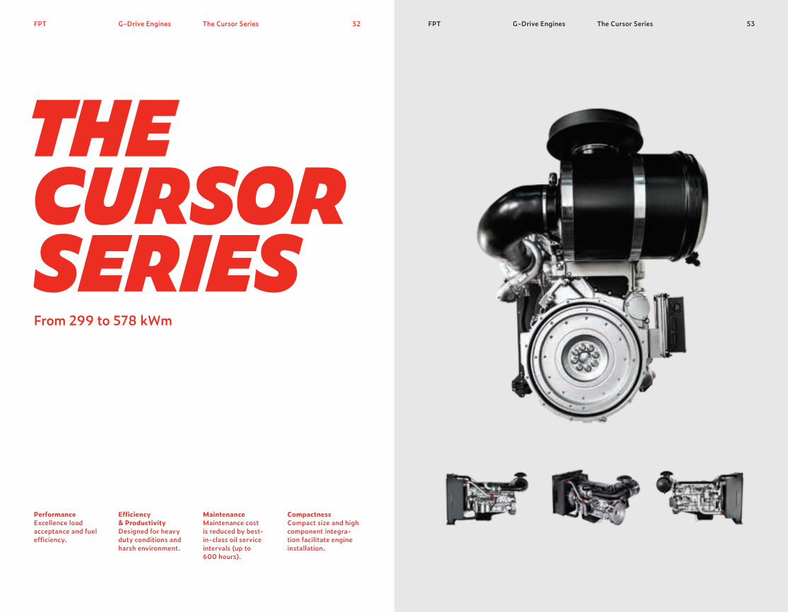
52 53FPT FPT G-Drive EnginesG-Drive Engines The Cursor Series
THE CURSOR SERIES
The Cursor Series
Performance Excellence load acceptance and fuel efficiency.
Efficiency & Productivity Designed for heavy duty conditions and harsh environment.
Maintenance Maintenance cost is reduced by best-in-class oil service intervals (up to 600 hours).
Compactness Compact size and high component integra-tion facilitate engine installation.
From 299 to 578 kWm

55FPT54FPT
C16 TEC87 TE
C13 TE
In the CURSOR Series, top power, fast load response and high-power density combine with low fuel consumption. The performance of this range is outstanding. High reliability, and extremely low operating costs thanks to long maintenance intervals, are its core values.
G-Drive Engines The Cursor Series G-Drive Engines The Cursor Series
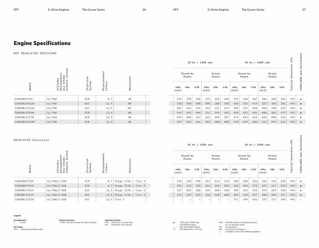
56 57FPT FPT G-Drive EnginesG-Drive Engines The Cursor Series
Legend Arrangement L In line Air Intake TAA Turbocharged Aftercooler
Exhaust System I-EGR Internal Exhaust Gas Recirculation
Injection System ECR Electronic Common Rail EUI Electronic Unit Injector
Model
Cyli
nder
Arra
ngemen
t Air
Int
ake
Exha
ust Syst
em
Inject
ion
Syst
em
Disp
lace
men
t Lite
rs
Emis
sion
s
CURSOR87TE43 CURSOR13TE2A3 CURSOR13TE3A3 CURSOR13TE6W CURSOR13TE7W CURSOR16TE1W3
6L/TAA 6L/TAA 6L/TAA 6L/TAA 6L/TAA 6L/TAA
ECR EUI EUI ECR ECR ECR
8,7
12,9
12,9
12,9
12,9
15,9
UR UR1 UR1 UR UR UR
NOT REGULATED EMISSIONS
Model
Cyli
nder
Arra
ngemen
t Air
Int
ake
Exha
ust Syst
em
Inject
ion
Syst
em
Disp
lace
men
t Lite
rs
Emis
sions
CURSOR87TE3F CURSOR87TE4F CURSOR13TE1F CURSOR13TE2F CURSOR13TE3X
6L/TAA/I-EGR 6L/TAA/I-EGR 6L/TAA/I-EGR 6L/TAA/I-EGR 6L/TAA/I-EGR
ECR ECR EUI EUI EUI
8,7
8,7
12,9
12,9
12,9
Stage IIIA / Tier 3 Stage IIIA / Tier 3 Stage IIIA / Tier 3 Stage IIIA / Tier 3 Tier 3
REGULATED Emissions
The Cursor Series
kVA kiloVolt Ampere calculations based on a 0.8 power factor UR Unregulated UR1 Previously EU Stage II 2 Complies to TA Luft (1986) regulations
1500 rpm / 1800 rpm switchable engine
Not Switchable Engine ** Fan absorption: 1%-6%
50 Hz / 1500 rpm 60 Hz / 1800 rpm
Typi
cal Ge
nera
tor eff.
1500/180
0 rp
m Sw
itch
able
Stand-by Power
Prime Power
Stand-by Power
Prime Power
kWm (net)
kWe kVA kWm (net)
kWe kVA kWm (net)
kWe kVA kWm (net)
kWe kVA
299
330
387
414
459
557
278
308
364
395
438
529
348
384
455
494
547
661
275
300
352
371
425
505
256
280
331
354
405
480
320
350
414
442
507
600
333
360
398
454
474
578
310
336
374
433
452
549
387
419
468
541
565
686
306
327
360
400
428
523
285
305
338
382
408
497
356
381
423
477
510
621
93%
93%
94%
95%
95%
95%
50 Hz / 1500 rpm 60 Hz / 1800 rpm
Typi
cal Ge
nera
tor eff.
1500/180
0 rp
m Sw
itch
able
Stand-by Power
Prime Power
Stand-by Power
Prime Power
kWm (net)
kWe kVA kWm (net)
kWe kVA kWm (net)
kWe kVA kWm (net)
kWe kVA
256
292
327
372 –
238
272
309
354 –
298
339
386
443 –
232
262
296
336 –
216
244
280
320 –
270
305
350
400 –
280
320
309
334
371
260
298
292
318
349
326
372
365
397
436
254
287
278
300
337
236
267
263
286
317
295
334
328
357
396
93%
93%
94%
95%
94%
Engine Specifications

58G-Drive EnginesFPT The Cursor Series 59G-Drive EnginesFPT The Cursor Series
Class G3 of ISO 8528 stand-ard certification of excellent performance related to load response. Accurate fuel delivery to achieve top performance in terms of load response and top power with low fuel consumption. Possibility to switch from 1500 rpm to 1800 rpm. User friendly thanks to interface card. Minimum cold starting tem-perature without auxiliaries down to -10°C (with grid heater down to -25°C).Most demanding Emissions performance achieved. Turbocharged with air-to-air charge cooled air system with 4 valves per cylinder to increase engine efficiency thanks to the optimization of thermodynamic.
CURSOR Series adopts combustion chambers and high pressure injection sys-tem optimized to reduce oil dilution. Worldwide service network. Engine ECU with CAN- BUS control & monitoring interfaces may be used for advanced real time diagnosis. Multiple injections, balancer counterweights incorporated in crankshaft webs, rear geartrain layout, camshaft in crankcase, suspended oil pan. Integrated CCV (Closed Crankcase Ventilation) system and engine design oriented to high component integration. Options for hot part guards, water jacket heater, alarm senders, oil drain systems, front radiator guard.
Excellent transient load response for several power generation applications. High engine thermodynamic performance with low fuel consumption. Engine adaptable to market request. High performance guaran-teed in all conditions. High engine power density with the shortest load response time.
Reduced maintenance needs and operating cost. Quick service support and easy maintenance. Vibration & noise reduction engine structural stiffness. Leakage prevention. Customer orientation and specific engine architecture based on application type.
Performance Injection System Dual Speed Mode Specific Features Air Handling
600h Oil Interval Change Serviceability & Maintainability Engine Design Component Integration Option List
Features Benefits Features Benefits
Key Advantages

61FPT G-Drive Engines60G-Drive EnginesFPT
Energy Solutions Powered by FPT IndustrialOur Power Generation offering includes open and soundproofed gensets as well as plant and after-sale services.The standard range covers the main applications, such as emergency services and self-generation.The line-up for the Power Generation segment includes the F5, NEF, and CURSOR series ranging from 30 to 500 kVA.
The products in FPT Industrial’s portfolio can be easily configured to suit usage needs.Power sets in containers provide high kVA output for emergency installations and for both on-shore and off-shore petroleum or gas platforms.Low-voltage distribution panels, specific shelters and resistances complete the product mix.
Our strong customer orientation allows us to respond to the peculiar require-ments of contractors such as Armed Forces, telcos and energy distributors. FPT’s products are tailor-built and supplied turnkey.
For FPT, respect for the environment is a clear commitment. In our genset installations, it goes hand in hand with outstanding performance.
63Power GenerationFPT Generator Sets62Power GenerationFPT Generator Sets
GENERATORSETS

64 65FPT FPT Generator SetsGenerator Sets Open Gensets
THE OPENGENSETSFrom 30 to 400 kVA
Open Gensets
Transportability Compact layout.
Refueling Operations Integrated fuel tank.
Maintenance Easy access for maintenance.
Compactness Manual or Automatic control panel

Generator SetsGenerator Sets Open Gensets Open Gensets 67FPT66FPT
SOUNDPROOFED GENSETS UNIQUE MODEL
Our open gensets range boasts a compact layout. The sets are built to satisfy demanding performance standards, using only high-quality components. Easy, inexpensive maintenance is an additional strong point. These products are best-in-class for oil and filters change intervals. FPT Industrial’s sets in this range are powered by low-emission engines. The engines use advanced solutions to optimize thermodynamic performance: this improves the load response and reduces the fuel consumption.
FPT FPT66

68 69FPT FPTGenerator Sets Open Gensets
Legend Air Intake NA Naturally Aspirated TAA Turbocharged Aftercooler TC Turbocharged
Injection System M Mechanical ECR Electronic Common Rail EUI Electronic Unit Injector
1. Performance according to ISO 8528 conditions. Power factor 0,82. Dry weight with standard accessories (may change depending on alternator type) UR Unregulated UR1 Previously EU Stage II
Power kVA1
50 Hz 60 Hz
Model
Prime Stand-by Prime Stand-by
GE F3230MA GE F3240MA GE F3250MA GE NEF45MA GENEF50M GE NEF60MA GE NEF75MA GENEF80M GE NEF85MA GE NEF100MA GENEF120M GENEF125M GENEF130MA GENEF160MA GENEF170M GENEF200EA GENEF200M GECURSOR250ED GECURSOR300ED GECURSOR350EA GECURSOR400EA
30 40 50 45 50 60 75 80 85
100
120
125
130
160
170
200
200
250
300
350
400
33
44
55
50
55
66
82
88
94
110
132
138
143
176
187
220
220
275
330
385
440
– – – –
55
66 –
85
100
110
125
138
145
170
170
225
200
270
330
380
420
– – – –
60
73 –
95
110
121
136
160
160
187
187
248
220
297
363
418
462
Engine SpecificationsNOT REGULATED EMISSIONS
Generator Sets Open Gensets
Stand-by PowerMaximum power available for a period of 500 hours/year with a mean load factor of 90% of declared stand-by power.No kind of overload is allowable for this use.
Glossary Prime PowerMaximum power available with varying loads for an unlimited number of hours. The average power output during a 24 h period of operation must not exceed 80% of the declared prime power between the prescribed maintenance intervals and at standard environmental conditions. A 10% overload is permissible for 1 hour every 12 hours of operation.
Open range – 30 to 400 kVAEngine specification Dimension (mm)
Dry Wei
ght
2
(Kg)
G-Dr
ive
CYL/AIR
Inta
ke
Inject
ion
Syst
em
Dipl
acemen
tLite
rs
Emis
sion
s
L W H
F32AM1A F32SM1A F32TM1A N45AM1A N45AM2 N45SM1A N45SM2A N45SM3 N45TM1A N45TM2A N45TM3 N67SM1 N67TM2A N67TM3A N67TM4 N67TE2A N67TM7 CURSOR87TE1D CURSOR10TE1D CURSOR13TE2A CURSOR13TE3A
4L / NA 4L / TC 4L / TAA 4L / NA 4L / NA 4L / TC 4L / TC 4L / TC 4L / TAA 4L / TAA 4L / TAA 6L / TC 6L / TAA 6L / TAA 6L / TAA 6L / TAA 6L / TAA 6L / TAA 6L / TAA 6L / TAA 6L / TAA
M M M M M M M M M M M M M M M
ECR M
ECR
EUI
EUI
EUI
3,2
3,2
3,2
4,5
4,5
4,5
4,5
4,5
4,5
4,5
4,5
6,7
6,7
6,7
6,7
6,7
6,7
8,7
10,3
12,9
12,9
UR1 UR1 UR1 UR1 UR UR1 UR1 UR UR1 UR1 UR UR UR1 UR1 UR UR1 UR UR1 UR1 UR1 UR1
1833
1833
1833
2300
2300
2300
2300
2300
2300
2300
2300
2800
2800
2800
2800
2800
2800
3020
3530
3530
3530
730
730
730
730
730
730
730
730
730
730
730
780
780
780
780
780
780
1055
1100
1100
1285
1416
1416
1416
1285
1285
1322
1322
1475
1475
1475
1475
1423
1423
1423
1423
1423
1423
1690
1730
1730
1820
590
635
730
852
1000
886
902
1110
1130
1160
1110
1300
1315
1440
1440
1570
1440
1950
2500
2750
2800

71FPT Generator Sets Open Gensets70Generator SetsFPT Open Gensets
Key Advantages
ReliabilityCompact layout and high quality level of components.
CustomizationManual or automatic control panel. 3P or 4P circuit breaker availability Automatic Transfer Switch (available as option).
Maintenance & Serviceability Best in class for oil and filters change intervals (600 hours). Easy access for maintenance operations. Environmental CarePowered by low Emissions engines.
FlexibilityIntegrated Fuel Tank (F5 series: 80 lt; NEF series: 180 lt; CURSOR series: 500 lt).
Air HandlingTurbocharged with air-to-air charge cooled air system with 4 valves per cyl-inder to increase the engine efficiency by the optimization of thermodynamic performance in terms of load response & fuel consumption.
SafetyHot parts protection grids availability.
72 73FPT FPTGenerator Sets SP Gensets
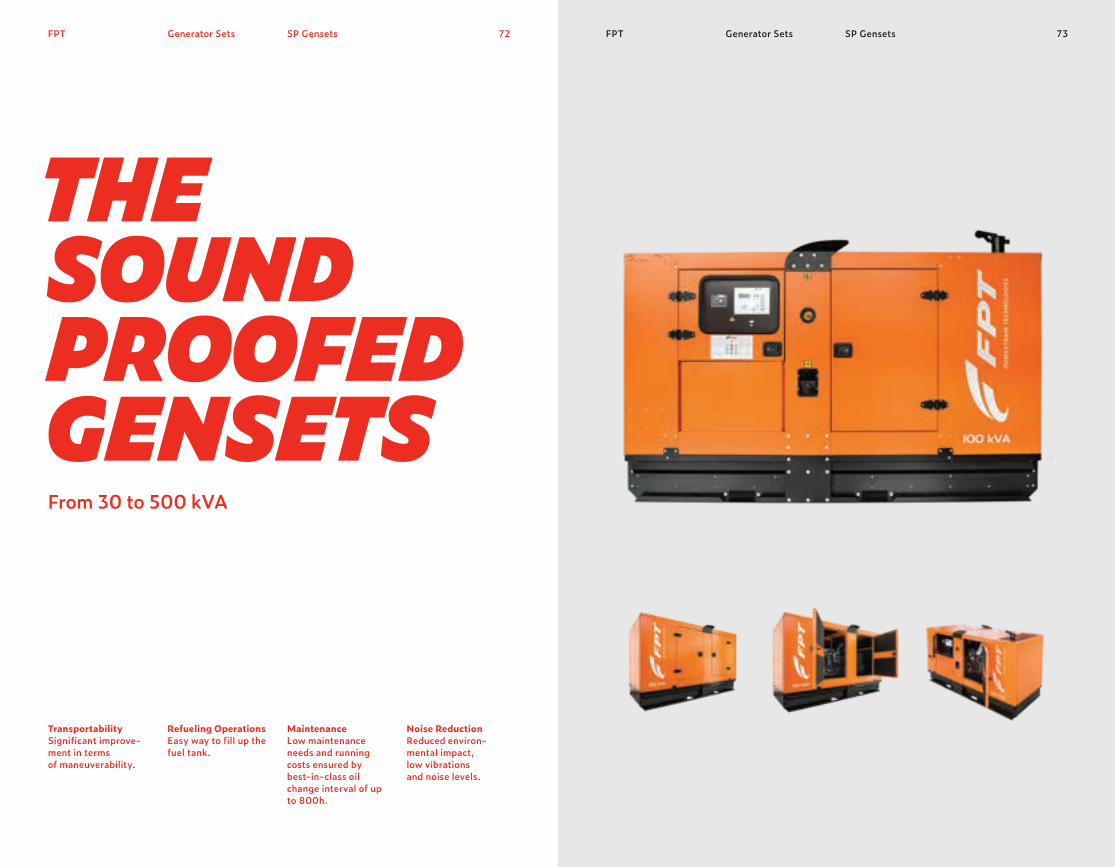
THESOUNDPROOFED GENSETSFrom 30 to 500 kVA
Transportability Significant improve-ment in terms of maneuverability.
Refueling Operations Easy way to fill up the fuel tank.
Maintenance Low maintenance needs and running costs ensured by best-in-class oil change interval of up to 800h.
Noise Reduction Reduced environ- mental impact, low vibrations and noise levels.
Generator Sets SP Gensets
75FPT74FPT
SOUNDPROOFED GENSETS UNIQUE MODEL
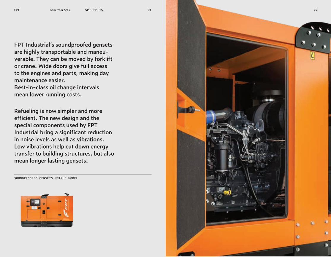
FPT Industrial’s soundproofed gensets are highly transportable and maneu-verable. They can be moved by forklift or crane. Wide doors give full access to the engines and parts, making day maintenance easier. Best-in-class oil change intervals mean lower running costs.
Refueling is now simpler and more efficient. The new design and the special components used by FPT Industrial bring a significant reduction in noise levels as well as vibrations. Low vibrations help cut down energy transfer to building structures, but also mean longer lasting gensets.
Generator Sets SP GENSETS

76 77FPT FPTGenerator Sets SP GENSETS
Legend Air Intake NA Naturally Aspirated TAA Turbocharged Aftercooler TC Turbocharged
Injection System M Mechanical ECR Electronic Common Rail EUI Electronic Unit Injector
1. Performance according to ISO 8528 conditions. Power factor 0,8 UR Unregulated UR1 Previously EU Stage II
Power kVA1
50 Hz 60 Hz
Model
Prime Stand-by Prime Stand-by
GS F3230 GS F3240 GS NEF45 GS NEF50-ne GS NEF60 GS NEF75 GS NEF80-ne GS NEF85 GS NEF100 GS NEF120-ne GS NEF125-ne GS NEF130 GS NEF160 GS NEF170-ne GS NEF200-ne GS NEF200 GS CURSOR250-ne GS CURSOR250 GS CURSOR300-ne GS CURSOR300 GS CURSOR350 GS CURSOR400 GS CURSOR500-ne
30 40 45 50 60 75 80 85
100
120
125
130
160
170
200
200
250
250
300
300
350
400
500
33
44
50
55
66
82
88
94
110
132
138
143
176
187
220
220
275
275
330
330
385
440
550
– – –
55
66
85
100
100
110
125
138
143
170
170
200
225
275
270
330
330
380
420
510
– – –
60
73
90
110
110
121
136
160
160
187
187
220
248
303
297
363
363
418
462
560
Engine SpecificationsNOT REGULATED EMISSIONS
Generator Sets SP GENSETS
Stand-by PowerMaximum power available for a period of 500 hours/year with a mean load factor of 90% of declared stand-by power.No kind of overload is allowable for this use.
Glossary Prime PowerMaximum power available with varying loads for an unlimited number of hours. The average power output during a 24 h period of operation must not exceed 80% of the declared prime power between the prescribed maintenance intervals and at standard environmental conditions. A 10% overload is permissible for 1 hour every 12 hours of operation.
Standards Soundproofed range – 30 TO 500 kVAEngine specification
G-Dr
ive
CYL/AIR
Inta
ke
Inject
ion
Syst
em
Dipl
acemen
tLite
rs
Emis
sion
s
F32AM1A F32SM1A N45AM1A N45AM2 N45SM1A N45SM2A N45SM3 N45TM1A N45TM2A N45TM3 N67SM1 N67TM2A N67TM3A N67TM4 N67TM7 N67TE2A CURSOR87TE3 CURSOR87TE1D CURSOR87TE4 CURSOR10TE1D CURSOR13TE2A CURSOR13TE3A CURSOR13TE7W
4L/NA 4L/TC 4L/NA 4L/NA 4L/TC 4L/TC 4L/TC 4L/TAA 4L/TAA 4L/TAA 6L/TC 6L/TAA 6L/TAA 6L/TAA 6L/TAA 6L/TAA 6L/TAA 6L/TAA 6L/TAA 6L/TAA 6L/TAA 6L/TAA 6L/TAA
M M M M M M M M M M M M M M M
ECR
ECR
ECR
ECR
EUI
EUI
EUI
ECR
3,2
3,2
4,5
4,5
4,5
4,5
4,5
4,5
4,5
4,5
6,7
6,7
6,7
6,7
6,7
6,7
8,7
8,7
8,7
10,3
12,9
12,9
12,9
UR1 UR1 UR1 UR UR1 UR1 UR UR1 UR1 UR UR UR1 UR1 UR UR UR1 UR UR1 UR UR1 UR1 UR1 UR
78Generator SetsFPT SP GENSETS
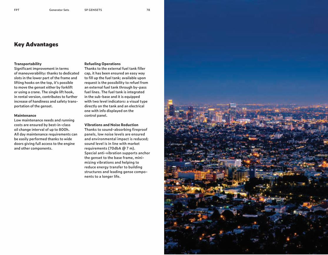
Key Advantages
TransportabilitySignificant improvement in terms of maneuverability: thanks to dedicated slots in the lower part of the frame and lifting hooks on the top, it’s possible to move the genset either by forklift or using a crane. The single lift hook, in rental version, contributes to further increase of handiness and safety trans-portation of the genset.
MaintenanceLow maintenance needs and running costs are ensured by best-in-class oil change interval of up to 800h. All day maintenance requirements can be easily performed thanks to wide doors giving full access to the engine and other components.
Refueling Operations Thanks to the external fuel tank filler cap, it has been ensured an easy way to fill up the fuel tank; available upon request is the possibility to refuel from an external fuel tank through by-pass fuel lines. The fuel tank is integrated in the sub-base and it is equipped with two level indicators: a visual type directly on the tank and an electrical one with info displayed on the control panel. Vibrations and Noise ReductionThanks to sound-absorbing fireproof panels, low noise levels are ensured and environmental impact is reduced; sound level is in line with market requirements (70dbA @ 7 m). Special anti-vibration supports anchor the genset to the base frame, mini- mizing vibrations and helping to reduce energy transfer to building structures and leading gense compo-nents to a longer life.

80FPT Generator Sets MRS72
MRS72Manual Control Panel with Remote Start
ok
ENGINE STATUS
GEN
MRS72 REMOTE START MANUAL CONTROLLER
OPTICAL INTERFACE
STOPSTART
81Generator SetsFPT MRS72
• Start up and shut down keys through an external signal.
• Engine and alternator parameters monitoring.
• “Manual” and “Super-manual” operational modes.
• Storage of last 250 events.
• Multilingual diagnostic software (Italian, English, French and Spanish).
• PC and/or on site (through optical key) programming.
• Battery charger to ensure correct battery efficiency and command/ control system alimentation (optional).

82FPT Generator Sets AMF74
AMF74Automatic Control Panel
MAINS
ok
ENGINE STATUS
GEN
AMF74 ADVANCED AUTOMATIC CONTROLLER
OPTICAL INTERFACE
STOPSTART
FPT 83Generator Sets AMF74
• Automatic start up when the volt-age of the main electrical network changes from a predefined value (programmable).
• Automatic insertion as main source of electrical energy as the working parameters are reached.
• Automatic disengagement once the nominal voltage of the main electri-cal network is reached.
• Programmable slow shut down to allow the engine cooling gradually.
• Engine and alternator parameters monitoring.
• “Manual”, “Automatic”, “Test“ and “Super-manual“ operational modes.
• Storage of last 250 events.
• Multilingual diagnostic software (Italian, English, French and Span-ish).
• PC and/or on site (through optical key) programming.
• Maintenance program indicating the routine maintenance to be per-formed.
• Battery charger to ensure correct battery efficiency and command/ control system alimentation (optional).

85Generator Sets
Through constant innovation, we can bring
the right answer wherever power is needed
quickly and reliably.
TIER4
86Power GenerationFPT Bare Engines
HI-ESCR87Power GenerationFPT Bare Engines
88 89FPT FPT
TIER4FINAL
Bare Engines Tier 4 Final
From 85 to 424 kWm
Performance Effective turbocharger solution and increased power density for best in class performance.
Efficiency & Productivity Low operating costs thanks to combustion efficiency and long service intervals.
Maintenance Maintenance-free af-ter-treatment solution for low running costs.
EGR Free Solution No additional cooling system requirements thanks to EGR free solution
Tier 4 FinalBare Engines
91Power GenerationFPT Titolo sezione90FPT
TIER 4 FINAL UNIQUE MODEL
Tier 4 Final standards bring a dramatic reduction in harmful NOx and PM, up to a 90% abatement from Tier 3. FPT Industrial is focusing its R&D activities to become the innovation leader in industrial powertrains, and the go-to reference provider of the most cost-effective solutions for Tier 4 Final.
Our breakthrough HI-eSCR technology meets the strictest emissions require-ments, while providing best-in-class performance and total running costs.FPT’s engines in this range also offer easier maintenance, reducing your downtime.
Tier 4 FinalBare Engines
92 93FPT FPTBare Engines Tier 4 Final
During the combustion process, inside a Diesel engine, the chemical energy is transformed into a mechanical one. Because of the chemistry of combus-tion, several toxic substances are pro-duced, of which the most harmful are Nitrogen Oxides (NOX) and Particulate Matter (PM). Tier4 Final compliance implies a signif-icant reduction of NOX and PM reaching a 90% abatement versus Tier3 Emis-sionsing step.
• NOX Emissions reduced by 90% compared to Tier3.• Introduction of an ammonia
Emissions limit.
Emission Standards Scenario
Bare Engines Tier 4 Final
Through continuous technical advances building upon a state-of-the-art engine range, Tier4 Final permits re-engi-neered engines, allowing our customers to retain their class-leading features, such as minimized total cost of owner-ship. Key to the optimization of com-bustion e ciency is high mean e ective cylinder pressure and high injector nozzle pressures.To achieve these goals, important changes to the crankcase and cylinder head design have been implemented. The engines tted with the latest gen-eration of multiple events Common Rail fuel injection equipment with peak nozzle pressures of up to 2200 bar. A new Electronic Control Unit has been introduced to manage both engine parameters and accurate control of the after-treatment system.
The new control unit has been designed to fully integrate engine and SCR functions. For the very best in envi-ronmental performance, the engines are equipped with closed circuit engine breathing systems.In addition, since the engine only breathes clean ltered air, rather than recirculated exhaust gases, engine wear maintenance is low with long intervals in between oil changes, with service intervals of up to 600h without increased oil sump. FPT Industrial Tier4 Final engines o er lower operating costs and reduced overall downtime for ease of maintenance.
Tier 4 Final Engines

94 95FPT FPTBare Engines Tier 4 Final
HI-eSCR System
System Description Due to the opposite reaction to com-bustion temperature, the reduction of either of the combustion products (NOX or PM) implies the increase of the other one. In order to further reduce NOX, as required by Tier4 Final, it is necessary to work on separate combustion man-agement and exhaust gas treatment systems simultaneously. This means that Tier4 Final Emissions limits can be reached only through the use of SCR (Selective Catalytic Reduc-tion), either with or without EGR. The use of an EGR system reduces the NOX Emissions in the combustion chamber, through exhaust gas recirculation with a consequential increase in the produc-tion of particulate matter (PM) and a reduction in combustion efficiency.
FPT Industrial has chosen instead to increase the engine combustion effi-ciency to reduce the PM without using EGR or DPF, allowing engines to work at peak performance without compro-mise. The resulting increase in NOX is reduced in the SCR system, while improving fuel efficiency and overall power system reliability.
FPT Industrial’s HI-eSCR solution is able to reduce NOX levels by more than 95%. The SCR Only technology allows for the introduction of a new integrated approach that is the result of extensive research by FPT Industrial, research that has led to the creation of numerous significant patents.
Bare Engines Tier 4 Final
Six Reasons to Choose HI-eSCR
Scr Heritage
Outstanding Performance
Fuel Consumption
Compact Packaging
Maintenance Intervals
High Reliability
FPT Industrial’s heritage in SCR technology is well-estab-lished. Since 2005 we have equipped more than 1.000.000 vehicles with this technology.
Our engines are developed to maximize power density with the shortest load response time with minimal impact on the environment, due to the use of the HI-eSCR system.
The efficiency of the combustion process optimizes fuel con-sumption reducing customer operating costs.
Compared to competitor’s engines, the thermodynamic efficiency of the FPT Industrial solutions allows to maximize power output for each engine space requirement and com-plexity.
The optimized combustion process preserves oil’s physi-cal properties reducing maintenance activities and related downtime. The engines maintain their best in class oil maintenance intervals of up to 600h, without an increased oil sump.
HI-eSCR system allows the engine to reduce heat rejec-tion of many internal engine components which leads to increased reliability.

96 97FPT FPTBare Engines Tier 4 Final
CO
HCCO
N
H OCO
NOX
NH NOx
N H O
NH
CO
1
3
2
4
4
5
6
7
5. DEF/AdBlue Mixer 6. Selective Catalytic Reduction (SCR) NO and NO2 reduction by NH3 to N2 and H2O 7. Clean Up Catalyst Residual NH3 oxidation *AdBlue®/DEF = CO(NH2)2 + H2O
1. DEF/AdBlue Supply Module 2. DEF/AdBlue Dosing Module 3. Diesel Oxidation Catalyst (DOC) NO → NO2 HC, CO and PM oxidation 4. DEF/AdBlue Injection Hydrolysis → NH3+CO2
Legend PM Particulate MatterHC Unburnt Hydrocarbons
NOx Nitrogen OxidesCO Carbon Monoxide
N2 NitrogenCO2 Carbon DioxideH2O Water
Bare Engines Tier 4 Final
Main Components
The whole system is fitted with a net-work of integrated sensors to control the NOX and any excess of NH3 (ammo-nia) emitted. Exhaust gas flow com-ing from the engine enters the DOC, where NO is oxidized in NO2, in order to maximize SCR catalyst’s efficiency conversion. The ECU (Engine Control Unit), the brain behind the HI-eSCR system, checks, through a network of inte-grated sensors, the amount of Water-Urea (DEF/AdBlue) solution required to be injected into the exhaust pipe. To increase the durability of the injector, the Dosing Module is cooled with the engine coolant. The HI-eSCR after-treatment system adopts a catalyst converting NOX into Nitrogen (N2) and Water (H2O) thanks to the chemical reaction with a Water-Urea solution. In the end, the inte-grated CUC eliminates the remaining ammonia (NH3). The result is a reduc-tion of NOX over 95%.
Patents
• “Closed” loop control to allow pre-cise dosing of NOX and Ammonia sensors to provide accurate info on the composition of exhaust gases and reduce the use of DEF/AdBlue.
• NOX Adaptive DEF/AdBlue dosing
system in order to cut the level of NOX Emissions entering the SCR catalyst.
• Thermally insulated high turbulence mixing, to allow homogeneous hydrolysis of urea, creating correct distribution in exhaust gas flow.
• Improved exhaust gas temperature control to speed up SCR light-off in the cold part of Emissions cycle.
All the components of the HI-eSCR after-treatment system are contained in a compact, and fully enclosed structure thereby not impeding body building or chassis equipment moun-ting activities, and minimizing the weight impact.

98 99FPT FPTPower Generation
2H Energy Powered by FPT IndustrialLocated in France, at Fécamp, 2HE is an FPT Industrial company offering a wide range of tailored power generation solutions aimed to satisfy customers with specific needs, such as Armies, oil and gas companies, energy providers, nuclear power stations and hospitals. 2HE offer includes “turnkey” supply, engineering support, production and installation, together with assistance service and customer training.
The company portfolio is enriched by special products like 400 Hz units for airport applications, gensets in containers up to 6 MWatt, specific shelters, energy systems for off-shore installations, resistances and low voltage distribution panels (specifi-cally designed for nautical and nuclear applications). Thanks to its proven expertise to man-age complex project from blank sheet up to maintenance and service activity worldwide, 2HE is a reference in the highly specialized power generation segment.
Power Generation
Plant R&D Plant + R&D
Fécamp
Paris
London
UNITEDKINGDOM
FRANCE
Tier 4 Final Tier 4 Final
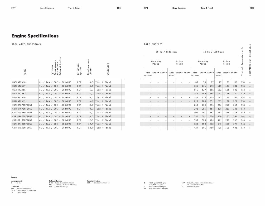
100 101FPT FPTBare Engines Tier 4 Final
Legend Arrangement L In line Air Intake NA Naturally Aspirated TAA Turbocharged Aftercooler TC Turbocharged
Exhaust System DOC Diesel Oxidation Catalyst SCR Selective Catalytic Reduction CUC Clean-up Catalyst
Injection System ECR Electronic Common Rail
Model
Cyli
nder
Arra
ngemen
t Air
Int
ake
Exha
ust Syst
em
Inject
ion
Syst
em
Disp
lace
men
t Lite
rs
Emis
sion
s
N45ENTZW681 N45ENTZW69 N67ENTZW611 N67ENTZW621 N67ENTZW68 N67ENTZW69 CURSOR87ENTZW61 CURSOR87ENTZW62 CURSOR87ENTZW68 CURSOR87ENTZW69 CURSOR13ENTZW61 CURSOR13ENTZW68 CURSOR13ENTZW69
4L / TAA / DOC + SCR+CUC 4L / TAA / DOC + SCR+CUC 6L / TAA / DOC + SCR+CUC 6L / TAA / DOC + SCR+CUC 6L / TAA / DOC + SCR+CUC 6L / TAA / DOC + SCR+CUC 6L / TAA / DOC + SCR+CUC 6L / TAA / DOC + SCR+CUC 6L / TAA / DOC + SCR+CUC 6L / TAA / DOC + SCR+CUC 6L / TAA / DOC + SCR+CUC 6L / TAA / DOC + SCR+CUC 6L / TAA / DOC + SCR+CUC
ECR ECR ECR ECR ECR ECR ECR ECR ECR ECR ECR ECR ECR
4,5
4,5
6,7
6,7
6,7
6,7
8,7
8,7
8,7
8,7
12,9
12,9
12,9
Tier 4 Final Tier 4 Final Tier 4 Final Tier 4 Final Tier 4 Final Tier 4 Final Tier 4 Final Tier 4 Final Tier 4 Final Tier 4 Final Tier 4 Final Tier 4 Final Tier 4 Final
Engine SpecificationsREGULATED EMISSIONS
Bare Engines Tier 4 Final
kVA kiloVolt Ampere calculations based on a 0.8 power factor 1. Preliminary data
1500 rpm / 1800 rpm switchable engine
Not Switchable Engine ** Fan absorption: 1%-6%
50 Hz / 1500 rpm 60 Hz / 1800 rpm
Typi
cal Ge
nera
tor eff.
1500/180
0 rp
m Sw
itch
able
Stand-by Power
Prime Power
Stand-by Power
Prime Power
kWm (gross)
kWe** kVA** kWm (gross)
kWe** kVA** kWm (gross)
kWe** kVA** kWm (gross)
kWe** kVA**
– – – – – – – – – – – – –
– – – – – – – – – – – – –
– – – – – – – – – – – – –
– – – – – – – – – – – – –
– – – – – – – – – – – – –
– – – – – – – – – – – – –
85
126
145
167
195
223
260
282
309
330
353
380
424
78
116
129
149
175
200
233
253
281
301
324
350
391
97
145
161
186
219
251
291
316
351
376
404
438
488
77
115
132
152
177
203
236
256
281
300
321
345
385
70
106
116
135
158
182
210
229
255
273
294
318
355
88
132
145
169
198
227
263
286
318
341
368
397
443
93%
93%
93%
93%
93%
93%
93%
93%
94%
94%
94%
95%
95%
BARE ENGINES

All the pictures, drawings illustrations and descriptions contained in this brochure are based on product information available to FPT Industrial at the time of printing (31/01/2018). Some of the engine line-ups may refer to a specific market configuration which may not be present or offered for sale available in all other markets. The colors featured in this brochure may differ from the originals. FPT Industrial reserves the right to introduce any modifications, at any time and without any prior advance notice, to design, material, components equipment and/or technical specifications.