powercode remote start system - machenrymachenry.com/documents/installation...
TRANSCRIPT

POWERCODE REMOTE START SYSTEM
POWERCODE REMOTE START KIT
A - PowerCodeModule
B - DNA-9Module
C - DNA-9Relay Harness
D- Hood Switch E- Di-PoleAntenna
F- 2-Way Fob G- 1-Way Fob H - PATSInterface Kit
(PIK)
I- Wire Harness
APPLICABLE REMOTE START PART NUMBERS
EE8J-19G364-AA EE8Z-19G364-D BE8Z-19G364-A BE8Z-19G364-B
EE8Z-19G364-C CM5Z-19G364-A CM5Z-19G364-B CM5Z-19G364-E
BE8Z-19G364-D CM5J-19G364-AB DM5J-19G364-AA AL2Z-19G364-A
CM5Z-19G364-F BE8Z-19G364-C 7L2Z-19G364-AA 9L5Z-19G364-A
9G1Z-19G364-A AG1Z-19G364-A 7L5Z-19G364-AA AC3Z-19G364-A
7W3Z-19G364-AA AW3Z-19G364-A 9C3Z-19G364-A AL1Z-19G364-B
AA5Z-19G364-A AA5Z-19G364-B AL1Z-19G364-A B4TRN-19G364-CA
AL3Z-19G364-A B4TRN-19G364-AA B4TRN-19G364-BA 7L3Z-19G364-AA
B4TRN-19G364-DA B4TRN-19G364-EA BE8J-19G364-C EE8Z-19G364-A
POWERCODE REMOTE START SYSTEM
Rev 1 (2-17-2016) Remote Start System Diagnosis 1
Page 1 of 11 © Copyright Ford 2016 FoMoCo

(Continued)EE8Z-19G364-B
PRINCIPLES OF OPERATIONThe PowerCode remote start system is a dealer installed product that starts the vehicle using a separate key fob. This Genuine FordAccessory system is not integrated into the existing key fob. The system is partially plug‐n‐play and, in many cases, hardwired into thevehicle's electrical system. The PowerCode system has an approximate range of up to 1000 ft (300 m) and controls the following:
• Starting the vehicle.
• Powering preset HVAC systems.
• Running for a programmed duration (10 minutes). Call 1-800-FORDKEY for directions to change to 15 minutes.
• Interfaces with the Passive Anti‐Theft System (PATS) to allow secure starting of vehicle.
• Activates the parking lights.
• Sounds the horn.
• Locks the doors (not applicable to the 2013-2015 Escape and the 2013-2015 C-Max).
• Shuts down with the hood open.
• Shuts down when the brake is applied.
• Shuts down when door opens (MyKey only).
• Shuts down when a key is inserted into the ignition cylinder.
• Fiesta vehicles equipped with push button start will shut down upon pressing unlock on the Intelligent Access (IA) key fob or when thevehicle unlocks through user contact with the door handle.
INSPECTION, VERIFICATION AND PHYSICAL DAMAGE1. Verify correct part number is used for vehicle and model year being installed.
2. Was the part damaged when it was received?
NOTE:If at the end of the troubleshooting process a replacement part is required, the supplier’s (Voxx Hirschmann) warranty request form will requirea detailed description of the suspected failure. Please include such details as VIN, user inputs to induce the failure, vehicle response (hornsounds, IPC messages), and DTCs for each vehicle module."
FAILURE DESCRIPTIONS COVERED1. TRANSMITTERS WILL NOT WORK – PINPOINT TEST A
2. CANNOT PROGRAM TRANSMITTERS – PINPOINT TEST A
3. NO RESPONSE FROM SYSTEM – PINPOINT TEST B
4. VEHICLE WILL NOT START – PINPOINT TEST C
5. NO RESPONSE FROM SYSTEM – PINPOINT TEST D
6. ONLY THE HORN SOUNDS WHEN ATTEMPTING REMOTE START – PINPOINT TEST E
PINPOINT TEST A – TRANSMITTERS WILL NOT WORK / PROGRAMPossible Causes
• Transmitters not programmed.
• Antenna issue.
• Depleted battery.
• Press and Hold vs. Double Press selected.
A1 – VERIFY PREVIOUS TRANSMITTER OPERATION
Is this is a first time installation of the transmitters or a previous installation that has stopped working after initial install or use?
Did the transmitters previously operate correctly?
POWERCODE REMOTE START SYSTEM
Rev 1 (2-17-2016) Remote Start System Diagnosis 2
Page 2 of 11 © Copyright Ford 2016 FoMoCo

• YES - GO TO A5.
• NO - GO TO A2.
A2 – VERIFY TRANSMITTER PROGRAMMING
If the transmitters have not been programmed, perform the following Transmitter Programming procedure:
Transmitter Programming Procedure:
1. Turn key to the RUN position (all the way forward).
2. Press and hold the brake pedal.
NOTE:For PEPS Taurus/MKS, use hood open instead of brake pedal.
3. Press and hold the programming button wired to the system.
4. Wait 15 seconds until the system sounds the horn 3 times.
5. Press the START button on the transmitter until the system responds by sounding the horn.
Did the transmitters program?
• YES – Verify proper function and continue installation.
• NO – Transmitter failed to enter Programming Mode, GO TO A3.
• NO – Transmitter entered programming but failed to program, GO TO A4.
A3 – SYSTEM FAILS TO ENTER PROGRAMMING MODE
If the system fails to enter Programming Mode, verify the system has the following inputs by referring to the vehicle specific installation sheetsfor proper wire color, polarity and location.
• Verify 12V+.
• Verify ground.
• Verify ignition (with key is in the RUN position).
• Verify brake.
• Verify programming button ground input (when pressing the programming button).
Did the above checks correct the issue?
• YES – Verify proper function and continue installation.
• NO – GO TO PINPOINT TEST B.
A4 – VERIFY ANTENNA IS CONNECTED
If the system enters Programming Mode but will not respond to a transmitter, verify the antenna or In Vehicle Unit (IVU) (whichever isapplicable) is properly connected at the following points:
• Verify the IVU/antenna is connected to the PowerCode module.
• Verify the IVU/antenna cable is not cut or shorted.
• Verify the harness is connected to the IVU (if applicable).
• Verify the antenna terminals on the module are not bent or broken.
Did the above checks correct the issue?
• YES – Verify proper function and continue installation.
• NO – GO TO A5.
A5 – DEPLETED BATTERY
The transmitters have internal batteries that are expected to wear down under normal use or shelf life. Under certain conditions, such asstorage conditions and how many times it is used each day, can deplete the batteries more quickly. If the LED (if equipped) on the transmitter
POWERCODE REMOTE START SYSTEM
Rev 1 (2-17-2016) Remote Start System Diagnosis 3
Page 3 of 11 © Copyright Ford 2016 FoMoCo

is not lighting when activated, is dimly lit, or the unit has been in service for an extended period of time, the battery should be checked and/orreplaced. This is considered normal wear and tear and is not a warrantable item.
Did replacing the transmitter battery correct the issue?
• YES – Verify proper function and continue installation.
• NO – GO TO PINPOINT TEST B.
A6 – DOUBLE PRESS VS. PRESS and HOLD
Remote start systems can be activated by either a Double Press or a Press and Hold method. This is a programmable option that could havebeen changed by either the customer or the dealer technician. Occasionally a technician may also accidentally change an option unknowingly,so verification of this setting may be necessary. A technician should attempt starting the system using both methods before proceeding. Thefollowing option can be changed if required:
• Option Bank 2, Option 4 ‐ Transmitter Press / Press and Hold Mode
Did attempting to start with the alternate method or changing the option correct the issue?
• YES – Verify proper function and continue installation.
• NO – GO TO PINPOINT TEST B.
PINPOINT TEST B – NO RESPONSE FROM SYSTEMPossible Causes
• Connection made improperly.
• Damaged connector or terminal.
• Blown or missing vehicle fuse.
• Blown 5A Gen-2 module fuse.
B1 – VERIFY ALL CONNECTORS ARE CONNECTED TO THE PROPER LOCATIONS
If any connector is improperly connected, the system will not respond. Verify the following connections have been made:
• Harness is plugged into the ignition switch (see vehicle specific installation instructions).
• Remote start module is plugged into the main wire harness.
• Antenna/harness is connected to the glass mounted IVU antenna.
• Antenna harness is connected to the remote start module.
Were any connections missing or shorted?
• YES – Verify proper function and continue installation.
• NO – GO TO B2.
B2 – VERIFY POWER AND GROUND SUPPLY
The module requires power and ground that should be verified at the module connector. Using a digital multimeter, verify the module has 12V+ on the RED wire in pin 4 of the 24‐way connector of the harness. Also verify the module has ground on the BLACK wire in pin 5 of the 24‐way connector of the harness.
POWERCODE REMOTE START SYSTEM
Rev 1 (2-17-2016) Remote Start System Diagnosis 4
Page 4 of 11 © Copyright Ford 2016 FoMoCo
NOTE:If the system responds to a transmitter in any way (for example a click or flash), there is power and ground present.
Did the module have missing power or ground?
• YES – If missing power, GO TO B3. If missing ground, repair the ground connection or replace the wire harness as needed.
• NO – GO TO B4.
B3 – VERIFY FUSES
If the module is not responding or any particular output is not functioning, check the fuses under the DNA cartridge to make sure they are notmissing, blown, or in the wrong position (see vehicle specific installation instructions).
Was a fuse blown, missing or in the wrong position?
• YES – Correct and retest.
• NO – GO TO B4.
B4 – VISUALLY INSPECT TERMINALS
All terminals of each connector on both the remote start product and the vehicle should be visually inspected for bent or damaged pins.
Were there any bent or damaged pins that could NOT be repaired?
• YES – Replace part, or service vehicle accordingly.
• NO – GO TO PINPOINT TEST A.
PINPOINT TEST C – VEHICLE WILL NOT STARTPossible Causes
• Two keys present near ignition switch.
• Missing or improper connections.
• Improper programming process.
C1 – VERIFY KEYS ARE NOT PRESENT IN THE VEHICLE
The vehicle will not start if there is a factory key within range of the PATS ring around the ignition switch. Verify that both keys are removedfrom close proximity of the ignition switch after cycling them. It is best to completely remove them from the vehicle to make sure they are notbeing picked up by the vehicle's receiver.
Did removing the keys allow for a successful remote start?
• YES – Verify proper function and continue installation.
• NO – GO TO C2.
C2 – MISSING OR IMPROPER CONNECTIONS
The remote start system requires that every connection be properly made for it to program and perform normally. Verify the followingconnections have been made:
• Verify the DNA‐9 harness is connected to the three pin connector on the DNA‐9 cartridge.
• Verify the DNA‐9 harness is connected to the correct connector at the steering column.
• Verify the DNA‐9 2‐pin harness is connected to the main wire harness 2‐pin connector.
Did correcting any missing or improperly placed connections correct the issue?
• YES – Verify proper function and continue installation.
• NO – GO TO C3.
POWERCODE REMOTE START SYSTEM
Rev 1 (2-17-2016) Remote Start System Diagnosis 5
Page 5 of 11 © Copyright Ford 2016 FoMoCo

The remote start system must be programmed to the vehicle to properly interface with the PATS. If you are getting a response to thetransmitter but no further activity (horn sounding on PEPS vehicles), or the ignition circuits are turning on but no crank is occurring (key startvehicles), this could be because the DNA‐9 was not programmed. Another common indication the DNA‐9 has not yet been programmed to thevehicle PATS is the presence of a No Key Detected display on the vehicle's instrument panel or center stack. To address this, follow thesesteps to program the DNA‐9 according to the vehicle type being worked on:
Key Start Vehicles1. Verify the DNA‐9 has been programmed to the vehicle PATS. If not programmed, the information display in the vehicle will show No Key
Detected when the ignition is powered if not programmed.
2. Verify output to the DNA‐9 harness from main harness. The optimal location to verify is at the 8‐pin connector on the DNA‐9 relay moduleconnector.
• Red wire should register 12‐volt constant power.
• Black wire should register ground when remote start is activated and will drop off after the vehicle has started.
3. Verify the following connections:
• 3‐pin connector from the DNA‐9 harness is connected to the 3‐pin connector on the back of the DNA cartridge (only two of the threewires are used).
• Verify the DNA‐9 harness Y-connection is connected to the correct connector at the steering column (PATS transceiver at ignitionswitch).
• Verify the 2‐pin connector from the DNA‐9 harness is connected to the mating 2‐pin connector on the main remote start harness (bothsides have matching red and black wires).
• Verify the DNA‐9 harness relay module is connected.
Perform the following steps to program the DNA-9.
NOTE:TIMING OF KEY CYCLES AND REMOTE START ACTIVATION IS CRITICAL.
• The 2 original vehicle ignition keys are required. The add-a-key function (Spare Key Programming) must be enabled (usually enabledfrom the factory but may have been turned off). Use the Integrated Diagnostic System (IDS) to enable the feature.
• Cycle first ignition key to the RUN position.
• Leave first ignition key on for approximately 5 seconds (seat belt warning chime is a good time indicator). When the seat belt chimestops, turn the key off and remove from the igntion.
• IMMEDIATELY! Cycle second ignition key to the RUN position.
• Leave the second ignition key on for approximately 5 seconds (seat belt warning chime is a good time indicator). When the seat beltchime stops, turn the key off and remove from the ignition.
• IMMEDIATELY! Remote start with keyfob.
• Ignition will power and vehicle will start if process was successful.
NOTE:Doors must be closed when activating.
Push Button Start Vehicles1. Verify the DNA‐9 has been programmed to the vehicle PATS. If not programmed, the vehicle cluster will not power when remote start is
activated.
2. Verify the following connections:
• Three pin connector from DNA‐9 harness is connected to the 3‐pin connector on the back of the DNA cartridge (only two of the threewires are used).
• Verify the DNA‐9 harness Y-connection is connected to the correct connector at the steering column (PATS transceiver at ignitionswitch).
• Verify the two pin connector from the DNA‐9 harness is connected to the mating 2‐pin connector on the main remote start harness (bothsides have matching red and black wires).
• Verify the DNA‐9 harness relay module is connected.
3. Verify output to DNA‐9 harness from the main harness. The optimal location to verify is at the 8‐pin connector on the DNA‐9 relay moduleconnector.
POWERCODE REMOTE START SYSTEM
C3 – VERIFY DNA‐9 HAS BEEN PROGRAMMED
Rev 1 (2-17-2016) Remote Start System Diagnosis 6
Page 6 of 11 © Copyright Ford 2016 FoMoCo
• Red should register 12‐volt constant power.
• Black wire should register ground when remote start is activated and will drop off after the vehicle has started.
Perform the following steps to program the DNA-9.
NOTE:This procedure only programs the PATS portion of the key into the Instrument Panel Cluster (IPC).
NOTE:It may be necessary to connect an external battery charger on hybrid vehicles. This will prevent the vehicle systems from disabling certainignition controlled circuits and to conserve battery power during programming.
• With an IA key in the vehicle, turn the ignition on by pushing the Start button without pressing the brake.
• From the scan tool menu, select the Toolbox icon. Select Body>Security>PATS Functions and follow the IDS on‐screen instructions toenter PATS security access.
• Once security access is granted, prepare the RMST module for PATS programming.
• IMPORTANT!! — Remove all IA keys from the vehicle and place on a workbench a minimum of 10 feet from the vehicle.
• Press and hold the brake pedal.
• Press and hold the RMST system override button on the RMST harness for at least 10 seconds.
After 10 seconds the horn will sound three times, indicating the system is now in learn mode.
• Release the brake pedal and the RMST override button.
The horn should sound four times.
• Quickly press and release the RMST button on the RMST key fob one time.
IMPORTANT!! — Verify the LED has turned on. This indicates the RMST module is ready for programming to the vehicle PATS. Thissimulates holding a transponder key to the vehicle's steering column.
• From the scan tool menu, select Program additional transponder key. Follow the on-screen prompts to program additional keys and toprogram the RMST system to the vehicle.
NOTE:You may need to perform this step TWICE in order to successfully program the RMST system.
• Disconnect the scan tool, and turn off the ignition when complete.
Did programming the DNA-9 correct the issue?
• YES – Verify proper function and continue installation.
• NO – Replace DNA‐9.
PINPOINT TEST D – NO RESPONSE FROM SYSTEMPossible Causes
• PIK not programmed.
• Antenna placement.
• Damage to antenna.
• Vehicle PATS key memory deleted.
D1 – PREVIOUSLY INSTALLED OR NEW INSTALLATION
Verify whether the installation was previously installed and working, or if this is a new installation.
Was this a product that previously worked but stopped?
• YES – GO TO D2.
• NO – First time installation, GO TO D3.
POWERCODE REMOTE START SYSTEM
Rev 1 (2-17-2016) Remote Start System Diagnosis 7
Page 7 of 11 © Copyright Ford 2016 FoMoCo

D2 – PATS KEY MEMORY RESET OR DELETED
In rare situations, a dealership technician may delete all previously programmed PATS key memory in order to delete lost keys or troubleshootother PATS related issues. If this happened, the PIK system would also be deleted and would require reprogramming.
Has the vehicle been serviced since the original installation date of the remote start?
• YES – GO TO D3.
• NO – GO TO D5.
D3 – PROGRAMMING THE PIK
A common indication that the PIK has not been programmed to the vehicle, or is not functioning properly is the presence of a fast blinking theftlight on the vehicle's dashboard or instrument panel. To address this, follow these steps:
PIK Programming Procedure:
• Verify you have two original and valid PATS enabled keys for the vehicle.
• Verify that both keys start the vehicle.
• Make sure both keys are not on the same key ring.
• Turn the ignition to the RUN position (all the way forward) using the first key.
• When the PATS light in the instrument cluster goes out, remove the key.
• Quickly insert the second key and turn to the RUN position.
• When the PATS light in the instrument cluster goes out, remove the key from the ignition switch.
• Immediately initiate a remote start using a programmed key fob.
• Once the ignition turns on, the vehicle will learn the PIK and allow the vehicle to successfully start.
Did the PIK successfully program and start the vehicle?
• YES – Verify proper function and continue installation.
• NO – GO TO D4.
D4 – ORIGINAL KEYS FOR PROGRAMMING
Verify both of the keys being used to place the vehicle into learn mode are able to start the vehicle.
Were both keys able to start the vehicle?
• YES – GO TO D5.
• NO – IDS must be used to program the PIK device.
D5 – PIK ANTENNA RING NOT PLACED CORRECTLY
Verify the PIK antenna ring is properly placed over the factory PATS ring around the ignition switch and has not shifted or been moved. Ifnecessary, mount it now or correct its position.
Did this correct the issue and allow the system to program properly?
• YES – Verify proper function and continue installation.
• NO – GO TO D6.
D6 – MISSING CONNECTIONS OR CIRCUITS
The PIK system requires that every connection be properly made for it to program and perform normally. Ensure the following connectionshave been made:
• Visually verify the PIK’s 4‐pin connector is connected to the proper port on the PowerCode module.
• Visually inspect the antenna ring for any physical damage.
• Use a digital voltmeter to verify there is continuity on the two black wires (pins 1 and 2) by unplugging the connector inside the PIK.These wires complete the antenna ring circuit from the PIK to the antenna ring and should not be an open circuit.
• Verify the RED wire is at pin 3 on the connector inside the PIK, and the BLACK wire is at pin 2 on the connector that plugs into thePowerCode module.
POWERCODE REMOTE START SYSTEM
Rev 1 (2-17-2016) Remote Start System Diagnosis 8
Page 8 of 11 © Copyright Ford 2016 FoMoCo
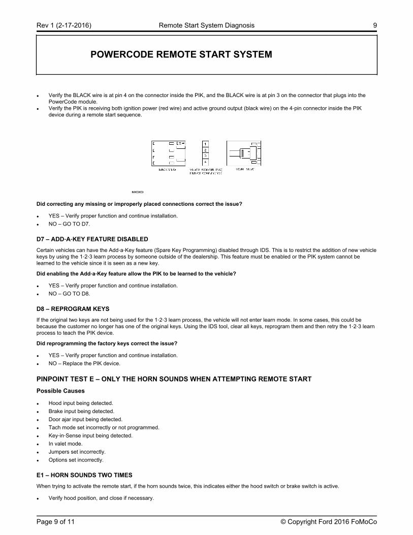
• Verify the BLACK wire is at pin 4 on the connector inside the PIK, and the BLACK wire is at pin 3 on the connector that plugs into thePowerCode module.
• Verify the PIK is receiving both ignition power (red wire) and active ground output (black wire) on the 4‐pin connector inside the PIKdevice during a remote start sequence.
Did correcting any missing or improperly placed connections correct the issue?
• YES – Verify proper function and continue installation.
• NO – GO TO D7.
D7 – ADD‐A‐KEY FEATURE DISABLED
Certain vehicles can have the Add‐a‐Key feature (Spare Key Programming) disabled through IDS. This is to restrict the addition of new vehiclekeys by using the 1‐2‐3 learn process by someone outside of the dealership. This feature must be enabled or the PIK system cannot belearned to the vehicle since it is seen as a new key.
Did enabling the Add‐a‐Key feature allow the PIK to be learned to the vehicle?
• YES – Verify proper function and continue installation.
• NO – GO TO D8.
D8 – REPROGRAM KEYS
If the original two keys are not being used for the 1‐2‐3 learn process, the vehicle will not enter learn mode. In some cases, this could bebecause the customer no longer has one of the original keys. Using the IDS tool, clear all keys, reprogram them and then retry the 1‐2‐3 learnprocess to teach the PIK device.
Did reprogramming the factory keys correct the issue?
• YES – Verify proper function and continue installation.
• NO – Replace the PIK device.
PINPOINT TEST E – ONLY THE HORN SOUNDS WHEN ATTEMPTING REMOTE STARTPossible Causes
• Hood input being detected.
• Brake input being detected.
• Door ajar input being detected.
• Tach mode set incorrectly or not programmed.
• Key‐in‐Sense input being detected.
• In valet mode.
• Jumpers set incorrectly.
• Options set incorrectly.
E1 – HORN SOUNDS TWO TIMES
When trying to activate the remote start, if the horn sounds twice, this indicates either the hood switch or brake switch is active.
• Verify hood position, and close if necessary.
POWERCODE REMOTE START SYSTEM
Rev 1 (2-17-2016) Remote Start System Diagnosis 9
Page 9 of 11 © Copyright Ford 2016 FoMoCo
• Verify hood switch is adjusted correctly and not registering a signal when closed.
• Verify the hood switch wire is not grounded or shorted between the switch and the PowerCode module. Test the hood switch input wirewith the hood closed to make sure the circuit is not showing ground. Correct as required.
• Verify the brake switch is not being pressed, or the brake lights are not on.
• Verify the brake switch wire is connected to the proper vehicle circuit and shows the proper response and polarity when actuating thebrake pedal (see vehicle specific installation instructions).
Did any of these correct the issue and allow the system to Remote Start?
• YES – Verify proper function and continue installation.
• NO – GO TO E8.
E2 – HORN SOUNDS THREE TIMES
When trying to activate the remote start, if the horn sounds three times, this indicates that a door or other entry point is open.
• Verify there are no doors or trunk/hatch locations open.
• Verify the door ajar wire is connected to the proper vehicle circuit and it shows the proper response and polarity when a door is both openand closed (see vehicle specific installation instructions).
• Verify the jumper is in the proper physical position.
• Verify the option for door ajar input polarity is programmed properly (Call 1-800-FORDKEY for instructions).
Did this correct the issue and allow the system to remote start?
• YES – Verify proper function and continue installation.
• NO – GO TO E6.
E3 – HORN SOUNDS FOUR TIMES
When trying to activate the remote start, if the horn sounds 4 times, this indicates the remote start system is currently set to require a tachsignal, but the tach signal is not programmed.
• Refer to the vehicle specific installation sheet to determine if a tach signal must be learned for the particular year/model being equippedwith the remote start product.
• If the vehicle will not learn the tach signal, verify the proper wire has been targeted and using a DMM, check the signal at the tach inputwire at the module.
• If the system requires the unit to be placed in tachless mode, refer to the vehicle specific installation sheets.
Did this correct the issue and allow the system to remote start?
• YES – Verify proper function and continue installation.
• NO – GO TO E8.
E4 – HORN SOUNDS FIVE TIMES
When trying to activate the remote start, if the horn sounds 5 times, this indicates the remote start system is currently detecting a key‐in‐sensesignal is present.
• Verify no key is present in the ignition switch, if so remove it.
• Verify the key‐in sense wire is properly seated in the wire harness connector and shows the proper response and polarity when the key isboth in and out of the ignition switch (see vehicle specific installation instructions).
• Verify the jumper is in the proper physical position (see vehicle specific installation instructions).
• Verify the option for key‐in sense input polarity is programmed properly (Call 1-800-FORDKEY for instructions).
Did this correct the issue and allow the system to remote start?
• YES – Verify proper function and continue installation.
• NO – GO TO E6.
POWERCODE REMOTE START SYSTEM
Rev 1 (2-17-2016) Remote Start System Diagnosis 10
Page 10 of 11 © Copyright Ford 2016 FoMoCo
When trying to activate the remote start, if the horn sounds 6 times, this indicates the remote start system is currently in Valet Mode. To exitValet Mode, turn the ignition on, depress the brake pedal and press the transmitter button 3 times. The horn will sound once.
Did this correct the issue and allow the system to remote start?
• YES – Verify proper function and continue installation.
• NO – GO TO E8.
E6 – VERIFY JUMPERS
If the module is not responding properly or sounding the horn indicating it has detected a safety input, check the jumpers under the DNAcartridge to make sure they are not missing or in the wrong position (see vehicle specific installation instructions for specific position pervehicle).
Was a jumper missing or in the wrong position?
• YES – Correct and retest.
• NO – GO TO E7.
E7 – PROGRAMMABLE OPTIONS SET INCORRECTLY
There are several programmable options within the system not shown to the dealer in the installation sheets. Occasionally a technician mayaccidentally change an option and cause issues with a system's ability to function properly. For anything related to programming options, call1-800-FORDKEY.
Were any programmable options incorrectly set?
• YES – Verify proper function and continue installation.
• NO – GO TO E8.
E8 – PHYSICAL DAMAGE / BENT PINS
Occasionally during the installation process, a wire harness terminal may be bent upon making connections. Or, while connecting the DNA tothe PowerCode module, one of the pins could become bent and not make a connection. Carefully inspect all pins at each connector andbetween the DNA / PowerCode module and repair if possible.
Was the damaged part repairable and did it correct the issue?
• YES – Verify proper function and continue installation.
• NO – Replace part.
POWERCODE REMOTE START SYSTEM
E5 – HORN SOUNDS SIX TIMES
Rev 1 (2-17-2016) Remote Start System Diagnosis 11
Page 11 of 11 © Copyright Ford 2016 FoMoCo