powermonitor 500 unit user manual, publication 1420...
TRANSCRIPT

PowerMonitor 500 UnitCatalog Numbers 1420-V1, 1420-V2, 1420-V1A, 1420-V1P, 1420-V2A, 1420-V2P, 1420-V1-ENT, 1420-V1-485, 1420-V2-ENT, 1420-V2-485, 1420-V1A-ENT, 1420-V1A-485, 1420-V2A-ENT, 1420-V2A-485, 1420-V1P-ENT, 1420-V1P-485, 1420-V2P-ENT, 1420-V2P-485
User ManualOriginal Instructions
Important User Information
Read this document and the documents listed in the additional resources section about installation, configuration, and operation of this equipment before you install, configure, operate, or maintain this product. Users are required to familiarize themselves with installation and wiring instructions in addition to requirements of all applicable codes, laws, and standards.
Activities including installation, adjustments, putting into service, use, assembly, disassembly, and maintenance are required to be carried out by suitably trained personnel in accordance with applicable code of practice.
If this equipment is used in a manner not specified by the manufacturer, the protection provided by the equipment may be impaired.
In no event will Rockwell Automation, Inc. be responsible or liable for indirect or consequential damages resulting from the use or application of this equipment.
The examples and diagrams in this manual are included solely for illustrative purposes. Because of the many variables and requirements associated with any particular installation, Rockwell Automation, Inc. cannot assume responsibility or liability for actual use based on the examples and diagrams.
No patent liability is assumed by Rockwell Automation, Inc. with respect to use of information, circuits, equipment, or software described in this manual.
Reproduction of the contents of this manual, in whole or in part, without written permission of Rockwell Automation, Inc., is prohibited
Throughout this manual, when necessary, we use notes to make you aware of safety considerations.
Labels may also be on or inside the equipment to provide specific precautions.
WARNING: Identifies information about practices or circumstances that can cause an explosion in a hazardous
environment, which may lead to personal injury or death, property damage, or economic loss.
ATTENTION: Identifies information about practices or circumstances that can lead to personal injury or death, property
damage, or economic loss. Attentions help you identify a hazard, avoid a hazard, and recognize the consequence.
IMPORTANT Identifies information that is critical for successful application and understanding of the product.
SHOCK HAZARD: Labels may be on or inside the equipment, for example, a drive or motor, to alert people that dangerous
voltage may be present.
BURN HAZARD: Labels may be on or inside the equipment, for example, a drive or motor, to alert people that surfaces may
reach dangerous temperatures.
ARC FLASH HAZARD: Labels may be on or inside the equipment, for example, a motor control center, to alert people to
potential Arc Flash. Arc Flash will cause severe injury or death. Wear proper Personal Protective Equipment (PPE). Follow ALL
Regulatory requirements for safe work practices and for Personal Protective Equipment (PPE).
Table of Contents
Preface . . . . . . . . . . . . . . . . . . . . . . . . . . . . . . . . . . . . . . . . . . . . . . . . . . . . . . . .5About This Manual . . . . . . . . . . . . . . . . . . . . . . . . . . . . . . . . . . . . . . . . . . . . 5Summary of Changes . . . . . . . . . . . . . . . . . . . . . . . . . . . . . . . . . . . . . . . . . . . 5Intended Audience . . . . . . . . . . . . . . . . . . . . . . . . . . . . . . . . . . . . . . . . . . . . . 5Catalog Number Explanation . . . . . . . . . . . . . . . . . . . . . . . . . . . . . . . . . . . 5Access Product Release Notes . . . . . . . . . . . . . . . . . . . . . . . . . . . . . . . . . . . 6Additional Resources . . . . . . . . . . . . . . . . . . . . . . . . . . . . . . . . . . . . . . . . . . . 6
Chapter 1PowerMonitor 500 Unit Overview About the PowerMonitor 500 Unit. . . . . . . . . . . . . . . . . . . . . . . . . . . . . . 7
PowerMonitor 500 Features and Functions . . . . . . . . . . . . . . . . . . . . . . 8Front Panel Features. . . . . . . . . . . . . . . . . . . . . . . . . . . . . . . . . . . . . . . . . . . . 9Display Features. . . . . . . . . . . . . . . . . . . . . . . . . . . . . . . . . . . . . . . . . . . . . . . 11Selecting Data to Display . . . . . . . . . . . . . . . . . . . . . . . . . . . . . . . . . . . . . . 12
Chapter 2Installation and Wiring Installation . . . . . . . . . . . . . . . . . . . . . . . . . . . . . . . . . . . . . . . . . . . . . . . . . . . 15
Wiring Diagrams. . . . . . . . . . . . . . . . . . . . . . . . . . . . . . . . . . . . . . . . . . . . . . 17
Chapter 3Unit Configuration Configure with the Display . . . . . . . . . . . . . . . . . . . . . . . . . . . . . . . . . . . . 25
Configuration Flowchart . . . . . . . . . . . . . . . . . . . . . . . . . . . . . . . . . . . . . . 28Digital Filtering Operation. . . . . . . . . . . . . . . . . . . . . . . . . . . . . . . . . . . . . 33Analog Output Configuration Examples . . . . . . . . . . . . . . . . . . . . . . . . 36Alarm Configuration Example . . . . . . . . . . . . . . . . . . . . . . . . . . . . . . . . . 37
Chapter 4Communication EtherNet/IP Communication. . . . . . . . . . . . . . . . . . . . . . . . . . . . . . . . . . 39
Modbus Communication . . . . . . . . . . . . . . . . . . . . . . . . . . . . . . . . . . . . . . 45
Appendix APowerMonitor 500 Unit Data Tables
Summary of Data Tables . . . . . . . . . . . . . . . . . . . . . . . . . . . . . . . . . . . . . . . 49Geometric Representation of Power and Power Factor . . . . . . . . . . . 50Data Tables . . . . . . . . . . . . . . . . . . . . . . . . . . . . . . . . . . . . . . . . . . . . . . . . . . . 51
Appendix BTechnical Specifications List of Connectable Variables . . . . . . . . . . . . . . . . . . . . . . . . . . . . . . . . . . 74
Rockwell Automation Publication 1420-UM001F-EN-P - January 2017 3
Table of Contents
Appendix CPowerMonitor 500 EtherNet/IP Device Profile
General. . . . . . . . . . . . . . . . . . . . . . . . . . . . . . . . . . . . . . . . . . . . . . . . . . . . . . . 77Object Model and Interface . . . . . . . . . . . . . . . . . . . . . . . . . . . . . . . . . . . . 77Identity Object - CLASS CODE 0x0001. . . . . . . . . . . . . . . . . . . . . . . . 77Assembly Object - CLASS CODE 0x0004 . . . . . . . . . . . . . . . . . . . . . . 82Technical Notes. . . . . . . . . . . . . . . . . . . . . . . . . . . . . . . . . . . . . . . . . . . . . . . 85
Appendix DUnit Configuration - Base Firmware Revision 11 and Earlier
Configure with the Display . . . . . . . . . . . . . . . . . . . . . . . . . . . . . . . . . . . . 87Configuration Flowchart . . . . . . . . . . . . . . . . . . . . . . . . . . . . . . . . . . . . . . 90
Index . . . . . . . . . . . . . . . . . . . . . . . . . . . . . . . . . . . . . . . . . . . . . . . . . . . . . . . .95
4 Rockwell Automation Publication 1420-UM001F-EN-P - January 2017
Preface
About This Manual This manual contains detailed information on these topics:• Mounting and wiring of the unit• Wiring to native and optional communication port• Set-up and use of the display module• Information on metering functionality and measurements• Use of the display module for configuration, monitoring, and
commands• Discussion of communication options, functionality, configuration, and
operation• Alarm configuration and operation• PowerMonitor™ 500 data tables
Summary of Changes This manual contains new and updated information as indicated in the following table.
Intended Audience This manual is intended for qualified personnel. You need a basic understanding of electric power and energy theory and terminology, and alternating-current (AC) metering principles.
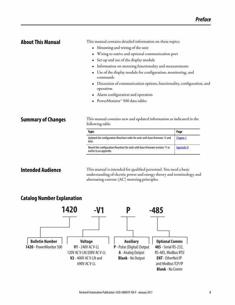
Catalog Number Explanation
Topic Page
Updated the configuration flowchart order for units with base firmware 12 and later.
Chapter 3
Moved the configuration flowchart for units with base firmware revision 11 or earlier to an appendix.
Appendix D
1420 -V1 P -485
Bulletin Number1420 - PowerMonitor 500
VoltageV1 - 240V AC V-LL
120V AC V-LN/208V AC V-LL
V2 - 400V AC V-LN and
690V AC V-LL
AuxiliaryP - Pulse (Digital) Output
A - Analog Output
Blank - No Output
Optional Comms485 - Serial RS-232,
RS-485, Modbus RTU
ENT - EtherNet/IP
and Modbus TCP/IP
Blank - No Comm
Rockwell Automation Publication 1420-UM001F-EN-P - January 2017 5
Preface
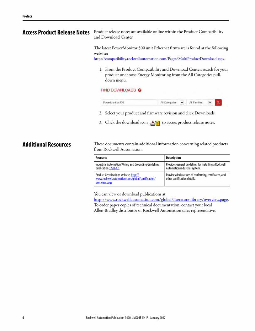
Access Product Release Notes Product release notes are available online within the Product Compatibility and Download Center.
The latest PowerMonitor 500 unit Ethernet firmware is found at the following website:http://compatibility.rockwellautomation.com/Pages/MultiProductDownload.aspx.
1. From the Product Compatibility and Download Center, search for your product or choose Energy Monitoring from the All Categories pull-down menu.
2. Select your product and firmware revision and click Downloads.
3. Click the download icon to access product release notes.
Additional Resources These documents contain additional information concerning related products from Rockwell Automation.
You can view or download publications athttp://www.rockwellautomation.com/global/literature-library/overview.page. To order paper copies of technical documentation, contact your local Allen-Bradley distributor or Rockwell Automation sales representative.
Resource Description
Industrial Automation Wiring and Grounding Guidelines, publication 1770-4.1
Provides general guidelines for installing a Rockwell Automation industrial system.
Product Certifications website, http://www.rockwellautomation.com/global/certification/overview.page
Provides declarations of conformity, certificates, and other certification details.
6 Rockwell Automation Publication 1420-UM001F-EN-P - January 2017
Chapter 1
PowerMonitor 500 Unit Overview
About the PowerMonitor 500 Unit
The PowerMonitor™ 500 unit is an AC power monitor with a built-in advanced configuration system and LCD data display. The unit is designed for measurement of electrical parameters in various three-phase, single-phase (2-wire European), and split-phase (3-wire North American single phase) circuits. The unit modular housing can be mounted in a panel that provides IP65 degree protection from the front. The power monitor can be provided with analog or digital (relay) outputs. These outputs can be selected to output a pulse proportional to the real and reactive energy that is measured, or to annunciate alarms. The instrument can also be equipped with a serial RS-485/RS-232 port or an EtherNet/IP port.
Equipped with an optional communication port, the unit communicates power and energy parameters to applications, such as FactoryTalk® EnergyMetrix™ software. The power monitor works with these software applications to address these key customer applications:
• Load profiling - log power parameters such as real energy, apparent power, and demand, for analysis of power usage by loads over time
• Cost allocation - report actual energy cost by department or process to integrate energy information into management decisions
• Billing and sub billing - charge users of energy the actual usage cost rather than allocating by square footage or other arbitrary methods
• Power system monitoring and control - display and control power flow and energy utilization
Rockwell Automation Publication 1420-UM001F-EN-P - January 2017 7
Chapter 1 PowerMonitor 500 Unit Overview
PowerMonitor 500 Features and Functions
The power monitor connects to your three-phase, split-phase (3-wire North American single phase), or single-phase (2-wire European) AC power system directly or through instrument transformers (PTs and CTs). It converts instantaneous voltage and current values to digital values, and uses the resulting digital values in calculations of voltage, current, power, energy, and demand.
The power monitor family includes several models that combine the following basic components:
• A panel-mounted power monitor in one of two AC voltage ranges: 120/208V or 400/600V
• An optional pair of digital (relay) outputs• An optional pair of 0…20 mA analog outputs• Optional serial RS-232/RS-485 communication supporting Modbus
RTU• Optional Ethernet port supporting EtherNet/IP and Modbus TCP/IP• Front protection degree: IP65, NEMA 4X, NEMA 12• Up to four configurable virtual alarms• Class 1 (kWh) according to EN62053-21• Class B (kWh) according to EN50470-3• Class 2 (kVARh) according to EN62053-23• Accuracy ±0.5% of reading (current/voltage)• Metering values display: Four rows with 4 digits• Energy value display: Ten digits and the plus/minus sign• Three-phase (system) variables: V(L-L), V(L-N), A, VA, W, VAR,
power factor, frequency• Single phase variables: V(L-L), V(L-N), A(L), An (calculated), VA, W,
VAR, power factor• System and single phase average and maximum variables• Energy measurements (imported/exported): kWh and kVARh• Revenue grade energy measurements per ANSI C12.1 Class 1.0, ANSI
C12.1• Run hours counter (8+2 digits)• Real-time clock function• Universal power supply: 120/240V AC 50/60 Hz, or 120/240V DC• Front dimensions: 96 x 96 mm (3.78 x 3.78 in)
8 Rockwell Automation Publication 1420-UM001F-EN-P - January 2017
PowerMonitor 500 Unit Overview Chapter 1
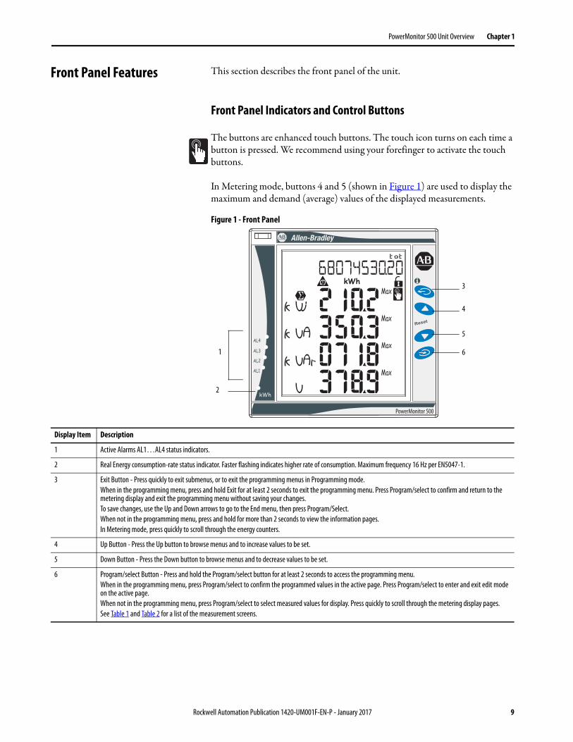
Front Panel Features This section describes the front panel of the unit.
Front Panel Indicators and Control Buttons
The buttons are enhanced touch buttons. The touch icon turns on each time a button is pressed. We recommend using your forefinger to activate the touch buttons.
In Metering mode, buttons 4 and 5 (shown in Figure 1) are used to display the maximum and demand (average) values of the displayed measurements.
Figure 1 - Front Panel
PowerMonitor 500
1
2
3
4
5
6
Display Item Description
1 Active Alarms AL1…AL4 status indicators.
2 Real Energy consumption-rate status indicator. Faster flashing indicates higher rate of consumption. Maximum frequency 16 Hz per EN5047-1.
3 Exit Button - Press quickly to exit submenus, or to exit the programming menus in Programming mode.
When in the programming menu, press and hold Exit for at least 2 seconds to exit the programming menu. Press Program/select to confirm and return to the metering display and exit the programming menu without saving your changes.
To save changes, use the Up and Down arrows to go to the End menu, then press Program/Select.
When not in the programming menu, press and hold for more than 2 seconds to view the information pages.
In Metering mode, press quickly to scroll through the energy counters.
4 Up Button - Press the Up button to browse menus and to increase values to be set.
5 Down Button - Press the Down button to browse menus and to decrease values to be set.
6 Program/select Button - Press and hold the Program/select button for at least 2 seconds to access the programming menu.
When in the programming menu, press Program/select to confirm the programmed values in the active page. Press Program/select to enter and exit edit mode on the active page.
When not in the programming menu, press Program/select to select measured values for display. Press quickly to scroll through the metering display pages.
See Table 1 and Table 2 for a list of the measurement screens.
Rockwell Automation Publication 1420-UM001F-EN-P - January 2017 9
Chapter 1 PowerMonitor 500 Unit Overview
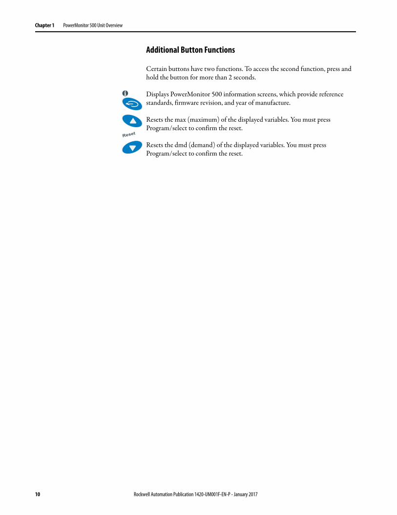
Additional Button Functions
Certain buttons have two functions. To access the second function, press and hold the button for more than 2 seconds.
Displays PowerMonitor 500 information screens, which provide reference standards, firmware revision, and year of manufacture.
Resets the max (maximum) of the displayed variables. You must press Program/select to confirm the reset.
Resets the dmd (demand) of the displayed variables. You must press Program/select to confirm the reset.
10 Rockwell Automation Publication 1420-UM001F-EN-P - January 2017
PowerMonitor 500 Unit Overview Chapter 1
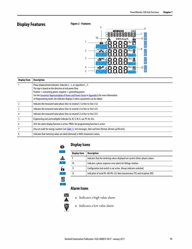
Display Features Figure 2 - Features
Display Icons
Alarm Icons
• Indicates a high value alarm
• Indicates a low value alarm
ROW
1RO
W2
ROW
3RO
W4
ROW
5
1
2
3
4
5
10
9 6
7
11
8
12
Display Item Description
1 Phase displacement indicator: inductive L, -L, or capacitive C, -C.
The sign is based on the direction of real power flow.
Positive = consuming power, negative = generating power.
See the Geometric Representation of Power and Power Factor in Appendix A for more information.
In Programming mode, the indicator displays E when a parameter can be edited.
2 Indicates the measured value phase (line-to-neutral L1 or line-to-line L12).
3 Indicates the measured value phase (line-to-neutral L2 or line-to-line L23).
4 Indicates the measured value phase (line-to-neutral L3 or line-to-line L31).
5 Engineering unit and multiplier indicator (k, M, V, W, A, var, PF, Hz, An).
6 ALR: the alarm display function is active. PROG: the programming function is active.
7 Area set aside for energy counters (see Table 1), text messages, date and time (format: dd.mm.yy/hh:mm).
8 Indicates that metering values are dmd (demand) or MAX (maximum) values.
Display Item Description
9 Indicates that the metering values displayed are system (three-phase) values.
10 Indicates a phase sequence error alarm for Voltage rotation.
11 Configuration lock switch is not active. Always indicates unlocked.
12 Indication of serial RS-485/RS-232 data transmission (TX) and reception (RX).
9
10
11
12
Rockwell Automation Publication 1420-UM001F-EN-P - January 2017 11
Chapter 1 PowerMonitor 500 Unit Overview
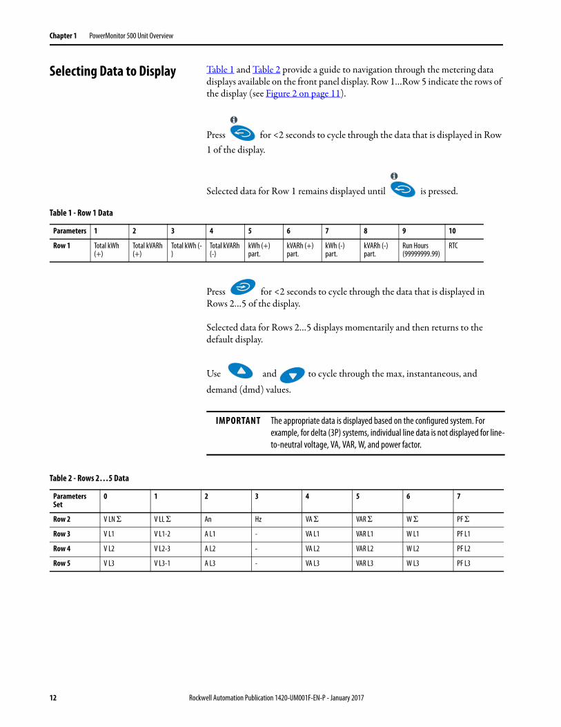
Selecting Data to Display Table 1 and Table 2 provide a guide to navigation through the metering data displays available on the front panel display. Row 1…Row 5 indicate the rows of the display (see Figure 2 on page 11).
Press for <2 seconds to cycle through the data that is displayed in Row 1 of the display.
Selected data for Row 1 remains displayed until is pressed.
Press for <2 seconds to cycle through the data that is displayed in Rows 2…5 of the display.
Selected data for Rows 2…5 displays momentarily and then returns to the default display.
Use and to cycle through the max, instantaneous, and
demand (dmd) values.
Table 1 - Row 1 Data
Parameters 1 2 3 4 5 6 7 8 9 10
Row 1 Total kWh (+)
Total kVARh (+)
Total kWh (-)
Total kVARh (-)
kWh (+) part.
kVARh (+) part.
kWh (-) part.
kVARh (-) part.
Run Hours (99999999.99)
RTC
IMPORTANT The appropriate data is displayed based on the configured system. For
example, for delta (3P) systems, individual line data is not displayed for line-
to-neutral voltage, VA, VAR, W, and power factor.
Table 2 - Rows 2…5 Data
Parameters Set
0 1 2 3 4 5 6 7
Row 2 V LN Σ V LL Σ An Hz VA Σ VAR Σ W Σ PF Σ
Row 3 V L1 V L1-2 A L1 - VA L1 VAR L1 W L1 PF L1
Row 4 V L2 V L2-3 A L2 - VA L2 VAR L2 W L2 PF L2
Row 5 V L3 V L3-1 A L3 - VA L3 VAR L3 W L3 PF L3
12 Rockwell Automation Publication 1420-UM001F-EN-P - January 2017
PowerMonitor 500 Unit Overview Chapter 1
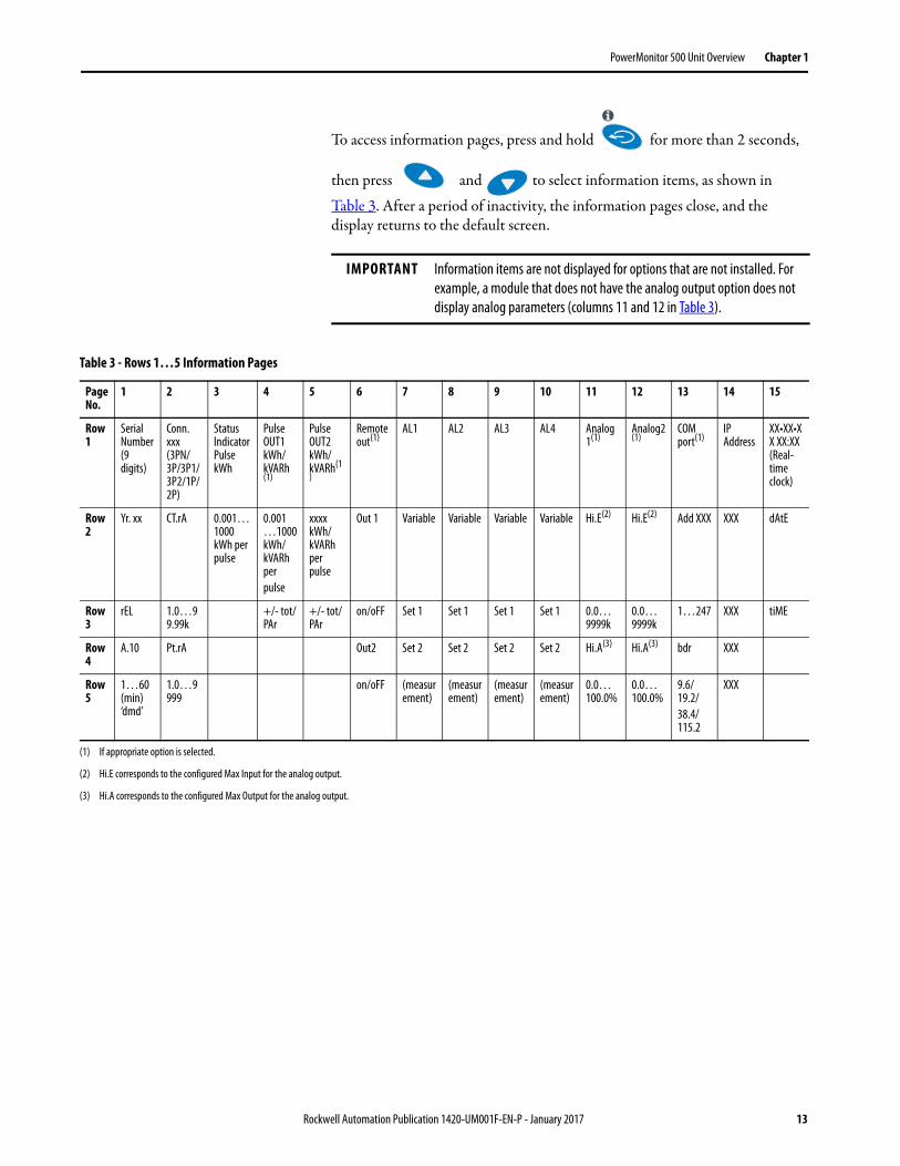
To access information pages, press and hold for more than 2 seconds,
then press and to select information items, as shown in
Table 3. After a period of inactivity, the information pages close, and the display returns to the default screen.
IMPORTANT Information items are not displayed for options that are not installed. For
example, a module that does not have the analog output option does not
display analog parameters (columns 11 and 12 in Table 3).
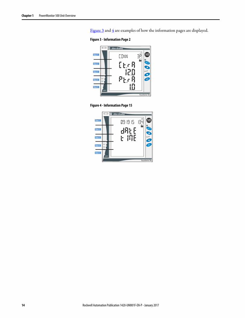
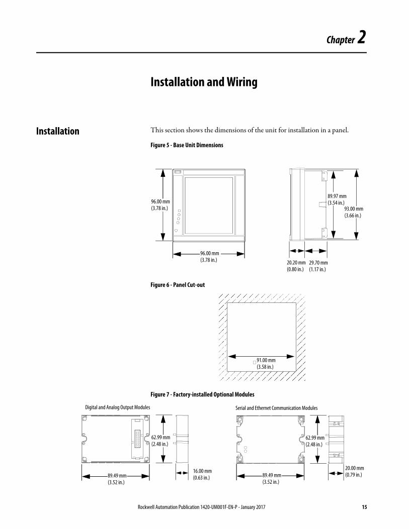
Table 3 - Rows 1…5 Information Pages
Page No.
1 2 3 4 5 6 7 8 9 10 11 12 13 14 15
Row 1
Serial Number (9 digits)
Conn. xxx (3PN/3P/3P1/3P2/1P/2P)
Status Indicator Pulse kWh
Pulse OUT1 kWh/kVARh(1)
Pulse OUT2 kWh/kVARh(1
)
Remote out(1)
AL1 AL2 AL3 AL4 Analog 1(1)
Analog2(1)
COM port(1)
IP Address
XX•XX•XX XX:XX (Real-time clock)
Row 2
Yr. xx CT.rA 0.001…1000 kWh per pulse
0.001…1000 kWh/kVARh per
pulse
xxxx kWh/kVARh per pulse
Out 1 Variable Variable Variable Variable Hi.E(2) Hi.E(2) Add XXX XXX dAtE
Row 3
rEL 1.0…99.99k
+/- tot/PAr
+/- tot/PAr
on/oFF Set 1 Set 1 Set 1 Set 1 0.0…9999k
0.0…9999k
1…247 XXX tiME
Row 4
A.10 Pt.rA Out2 Set 2 Set 2 Set 2 Set 2 Hi.A(3) Hi.A(3) bdr XXX
Row 5
1…60 (min) ‘dmd’
1.0…9999
on/oFF (measurement)
(measurement)
(measurement)
(measurement)
0.0…100.0%
0.0…100.0%
9.6/19.2/
38.4/115.2
XXX
(1) If appropriate option is selected.
(2) Hi.E corresponds to the configured Max Input for the analog output.
(3) Hi.A corresponds to the configured Max Output for the analog output.
Rockwell Automation Publication 1420-UM001F-EN-P - January 2017 13
Chapter 1 PowerMonitor 500 Unit Overview
Figure 3 and 4 are examples of how the information pages are displayed.
Figure 3 - Information Page 2
Figure 4 - Information Page 15
PowerMonitor 500
Row 1
Row 2
Row 3
Row 4
Row 5
PowerMonitor 500
Row 5
Row 4
Row 3
Row 2
Row 1
14 Rockwell Automation Publication 1420-UM001F-EN-P - January 2017
Chapter 2
Installation and Wiring
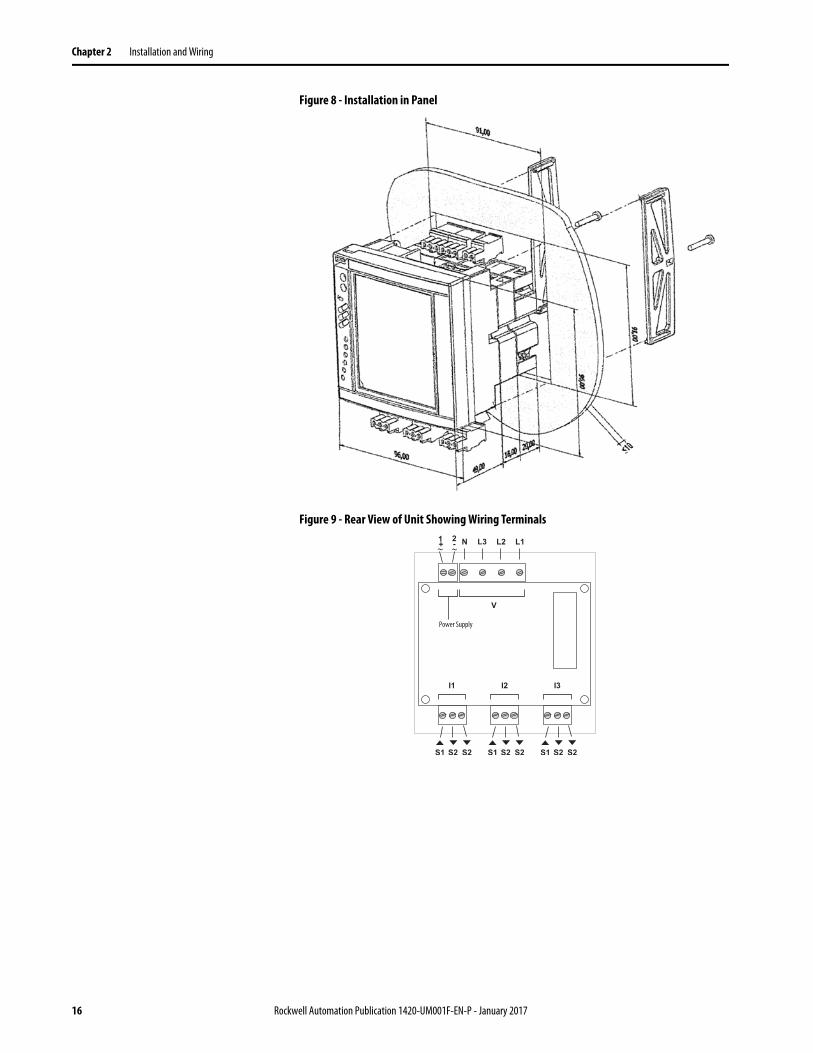
Installation This section shows the dimensions of the unit for installation in a panel.
Figure 5 - Base Unit Dimensions
Figure 6 - Panel Cut-out
Figure 7 - Factory-installed Optional Modules
96.00 mm(3.78 in.)
96.00 mm(3.78 in.) 93.00 mm
(3.66 in.)
20.20 mm(0.80 in.)
29.70 mm(1.17 in.)
89.97 mm(3.54 in.)
91.00 mm(3.58 in.)
62.99 mm(2.48 in.)
89.49 mm(3.52 in.)
62.99 mm(2.48 in.)
89.49 mm(3.52 in.)
16.00 mm(0.63 in.)
20.00 mm(0.79 in.)
Digital and Analog Output Modules Serial and Ethernet Communication Modules
Rockwell Automation Publication 1420-UM001F-EN-P - January 2017 15
Chapter 2 Installation and Wiring
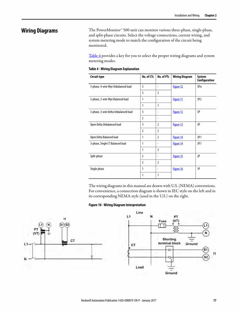
Figure 8 - Installation in Panel
Figure 9 - Rear View of Unit Showing Wiring Terminals
Power Supply
16 Rockwell Automation Publication 1420-UM001F-EN-P - January 2017
Installation and Wiring Chapter 2
Wiring Diagrams The PowerMonitor™ 500 unit can monitor various three-phase, single-phase, and split-phase circuits. Select the voltage connections, current wiring, and system metering mode to match the configuration of the circuit being monitored.
Table 4 provides a key for you to select the proper wiring diagrams and system metering modes.
The wiring diagrams in this manual are drawn with U.S. (NEMA) conventions. For convenience, a connection diagram is shown in IEC style on the left and in its corresponding NEMA style (used in the U.S.) on the right.
Figure 10 - Wiring Diagram Interpretation
Table 4 - Wiring Diagram Explanation
Circuit type No. of CTs No. of PTs Wiring Diagram System Configuration
3-phase, 4-wire Wye Unbalanced load 3 - Figure 12 3P.n
3 3
3-phase, 2-wire Wye Balanced load 1 - Figure 11 3P.2
1 1
3-phase, 3-wire Delta Unbalanced load 3 - Figure 13 3P
2 -
Open Delta Unbalanced load 3 2 Figure 13 3P
2 2
Open Delta Balanced load 1 2 Figure 14 3P.1
3-phase, Single CT Balanced load 1 - Figure 14 3P.1
1 3
Split-phase 2 - Figure 15 2P
2 2
Single phase 1 - Figure 16 1P
1 1
Rockwell Automation Publication 1420-UM001F-EN-P - January 2017 17

Chapter 2 Installation and Wiring
These diagrams are simplified. Wiring of the power monitor must comply with all applicable codes, standards, and regulations. Protect voltage and control power wiring with suitable overcurrent protection. Connect current transformer (CT) secondary wiring through a suitable shorting terminal block.
Figure 11 - 3-phase, 2-wire Wye, Balanced Load
Figure 12 - 3-phase, 4-wire Wye, Unbalanced Load
IMPORTANT In these diagrams, ‘balanced load’ configurations permit 3-phase
measurement by using only one phase connection. Unbalance in the
measured circuit affects the accuracy of the measurements.
Line
L 1 N
Fuse
PT
(VT )
Load
Ground
Shorting
terminal block
S 1I1
Ground
CT
1
L 2 L 3
L 1
S 2
N
Line
L 1 N
Fuse
Load
Ground
Shorting
terminal block
S 1I1
CT
1
L 2 L 3
L 1
S 2
N
PM 500 PM 500
1-CT Connection 1-CT and 1-PT/VT Connections
Meter Configuration: System = 3P.2
Line
L 1 N
Fuse
PT 1
(VT 1)
Load Ground
Shorting
terminal block
S 1I1
Ground
CT
1
L 2 L 3
L 1
S 2
PM 500
3-CT and 3-PT/VT Connections
S 1I2
CT
2S 2
S 1I3
CT
3S 2
Fuse
PT 2
(VT 2)
L 2
Fuse
PT 3
(VT 3)
L 3
N
Line
L 1 N
Fuse
Load Ground
Shorting
terminal block
S 1I1
CT
1
L 2 L 3
L 1
S 2
PM 500
3-CT Connection
S 1I2
CT
2S 2
S 1I3
CT
3S 2
Fuse
L 2
Fuse
L 3
N
Meter Configuration: System = 3P.n
18 Rockwell Automation Publication 1420-UM001F-EN-P - January 2017

Installation and Wiring Chapter 2
Figure 13 - 3-phase, 3-wire Delta, Unbalanced Load
Figure 14 - 3-phase, Single CT, Balanced Load
Line
L 1
Fuse
PT 1
(VT 1)
Load Ground
Shorting
terminal block
S 1I1
Ground
CT
1
L 2 L 3
L 1
S 2
PM 500
3-CT and 2-PT/VT Connections (Open Delta)
S 1I2
CT
2S 2
S 1I3
CT
3S 2
Fuse
L 2
PT 3
(VT 3)
L 3
N
Line
L 1
Fuse
Load Ground
Shorting
terminal block
S 1I1
CT
1
L 2 L 3
L 1
S 2
PM 500
3-CT Connection
S 1I2
CT
2S 2
S 1I3
CT
3S 2
Fuse
L 2
Fuse
L 3
N
Fuse
Meter Configuration: System = 3P
Line
Load Ground
PM 500
2-CT and 2-PT/VT Connections (ARON) (Open Delta)
Line
L 1
Fuse
Load Ground
Shorting
terminal block
S 1I1
CT
1
L 2 L 3
L 1
S 2
PM 500
2-CT Connection (ARON)
S 1I2
S 2
S 1I3
CT
3S 2
Fuse
L 2
Fuse
L 3
N
Shorting
terminal block
S 1I1
CT
1S 2
S 1I2
S 2
S 1I3
CT
3S 2
L 1
Fuse
PT 1
(VT 1)
Ground
L 2 L 3
L 1
Fuse
L 2
PT 3
(VT 3)
L 3
N
Fuse
Line
L 1 N
Fuse
PT 1
(VT 1)
Ground
L 2 L 3
L 1
PM 500
1-CT and 3-PT/VT Connections
Fuse
PT 2
(VT 2)
L 2
Fuse
PT 3
(VT 3)
L 3
N
Line
L 1 N
Fuse
L 2 L 3
L 1
PM 500
1-CT Connection
Fuse
L 2
Fuse
L 3
N
LinePM 500
1-CT and 2-PT/VT Connections
(Open Delta with balanced load)
LoadGround
Shorting
terminal block
S 1
S 2I1
CT
LoadGround
Shorting
terminal block
S 1
S 2I1
CT
LoadGround
Shorting
terminal block
S 1
S 2I1
CT
L 1
Fuse
PT 1
(VT 1)
Ground
L 2 L 3
L 1
Fuse
L 2
PT 3
(VT 3)
L 3
N
Fuse
Meter Configuration: System = 3P.1
Rockwell Automation Publication 1420-UM001F-EN-P - January 2017 19
Chapter 2 Installation and Wiring
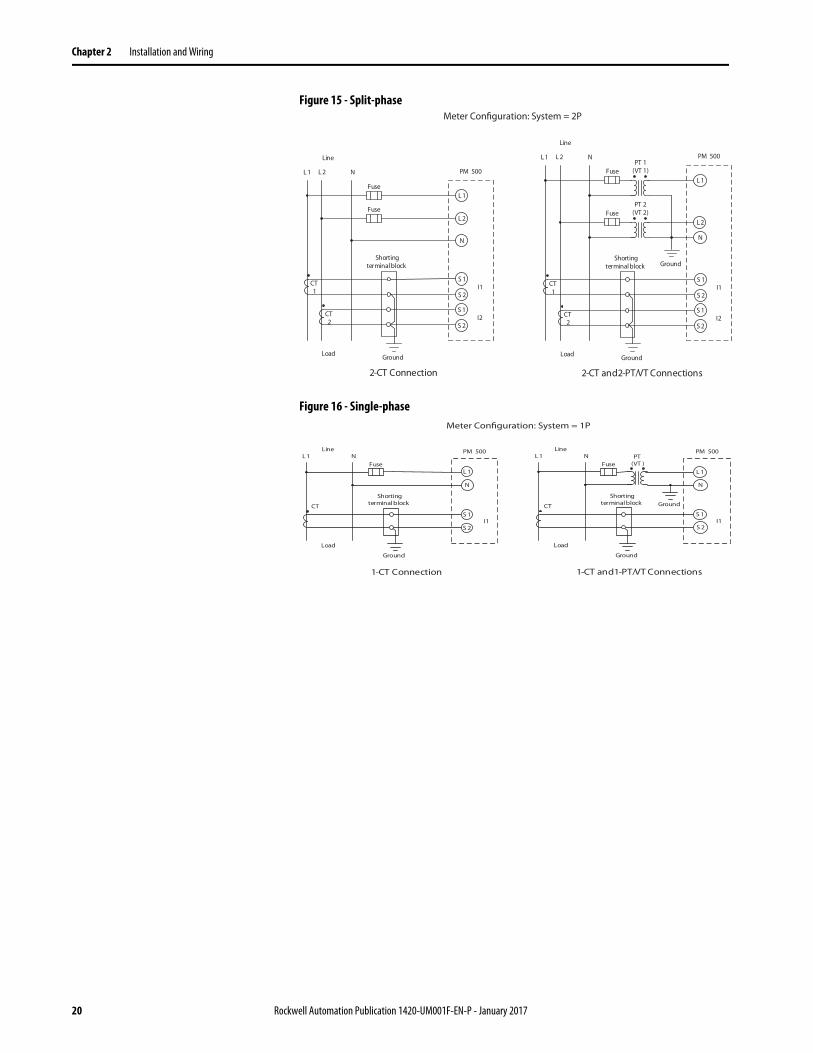
Figure 15 - Split-phase
Figure 16 - Single-phase
Line
L 1 N
Fuse
PT 1
(VT 1)
Ground
L 2
L 1
PM 500
2-CT and 2-PT/VT Connections
Fuse
PT 2
(VT 2)
L 2
Line
L 1 N
Fuse
LoadGround
Shorting
terminal block
S 1I1
CT
1
L 2
L 1
S 2
PM 500
2-CT Connection
S 1I2
CT
2S 2
Fuse
L 2
N
LoadGround
Shorting
terminal block
S 1I1
CT
1S 2
S 1I2
CT
2S 2
N
Meter Configuration: System = 2P
Line
L 1 N
Fuse
PT
(VT )
Load
Ground
Shorting
terminal block
L 1
N
S 1
S 2I1
GroundCT
Line
L 1 N
Fuse
Load
Ground
Shorting
terminal block
L 1
N
S 1
S 2I1
CT
PM 500 PM 500
1-CT Connection 1-CT and 1-PT/VT Connections
Meter Configuration: System = 1P
20 Rockwell Automation Publication 1420-UM001F-EN-P - January 2017
Installation and Wiring Chapter 2
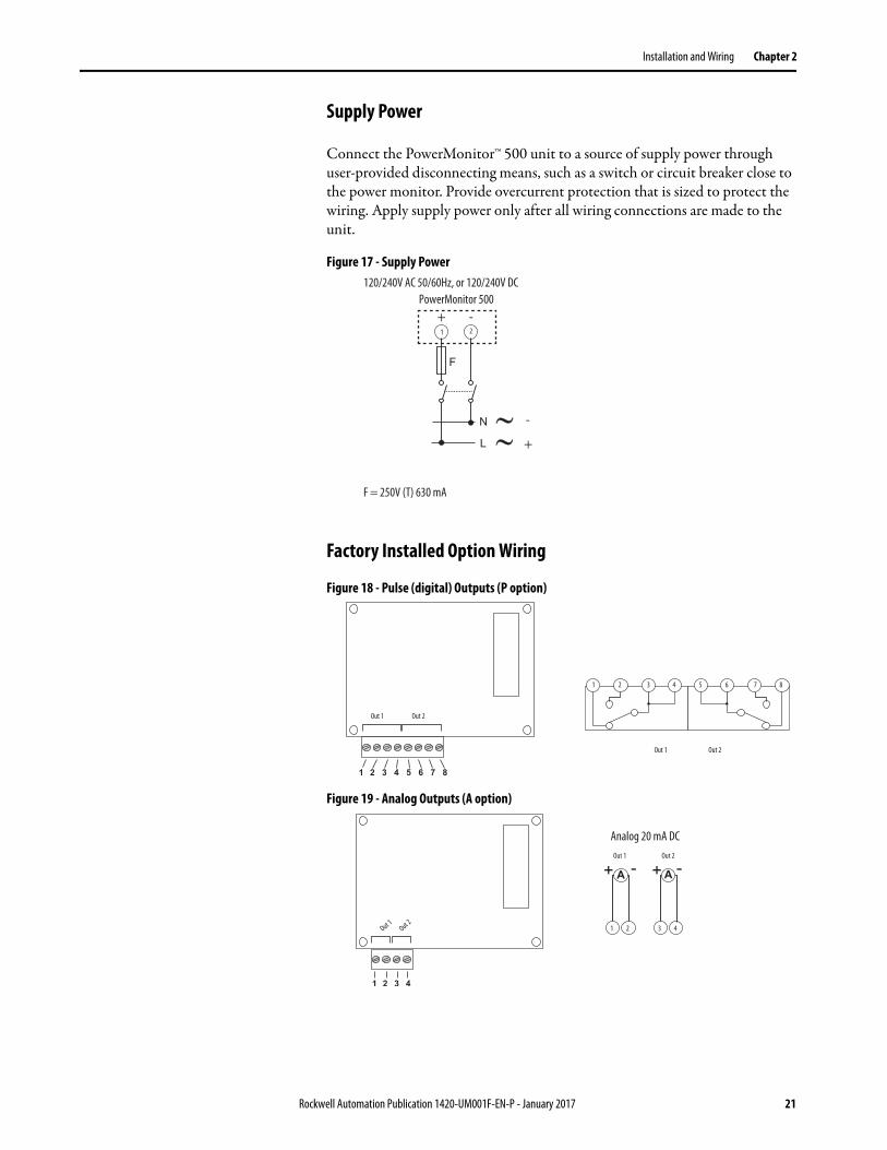
Supply Power
Connect the PowerMonitor™ 500 unit to a source of supply power through user-provided disconnecting means, such as a switch or circuit breaker close to the power monitor. Provide overcurrent protection that is sized to protect the wiring. Apply supply power only after all wiring connections are made to the unit.
Figure 17 - Supply Power
Factory Installed Option Wiring
Figure 18 - Pulse (digital) Outputs (P option)
Figure 19 - Analog Outputs (A option)
120/240V AC 50/60Hz, or 120/240V DC
PowerMonitor 500
F = 250V (T) 630 mA
21
+
+
-
-
Out 1 Out 2
Out 1 Out 2
21 43 65 87
1 432
Out 1 Out 2
Out 1Out 2
Analog 20 mA DC
Rockwell Automation Publication 1420-UM001F-EN-P - January 2017 21
Chapter 2 Installation and Wiring
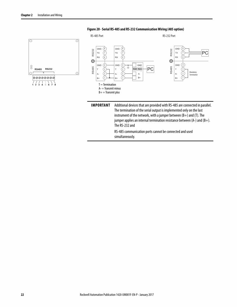
Figure 20 - Serial RS-485 and RS-232 Communication Wiring (485 option)
RS-485 Port RS-232 Port
6
7
8
1
2
3
4
6
7
8
1
2
3
4
6
7
8
1
2
3
4
Mandatory
Termination
T = TerminationA- = Transmit minusB+ = Transmit plus
IMPORTANT Additional devices that are provided with RS-485 are connected in parallel.
The termination of the serial output is implemented only on the last
instrument of the network, with a jumper between (B+) and (T). The
jumper applies an internal termination resistance between (A-) and (B+).
The RS-232 and
RS-485 communication ports cannot be connected and used
simultaneously.
22 Rockwell Automation Publication 1420-UM001F-EN-P - January 2017
Installation and Wiring Chapter 2
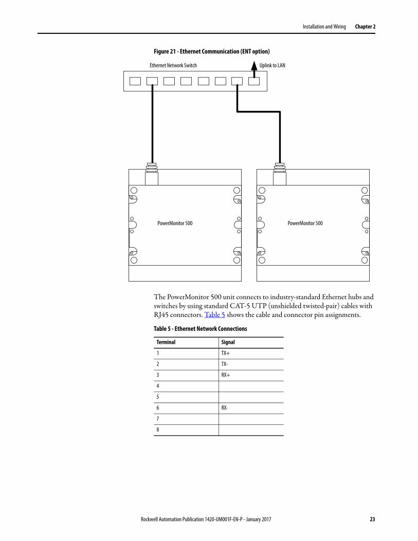
Figure 21 - Ethernet Communication (ENT option)
The PowerMonitor 500 unit connects to industry-standard Ethernet hubs and switches by using standard CAT-5 UTP (unshielded twisted-pair) cables with RJ45 connectors. Table 5 shows the cable and connector pin assignments.
Ethernet Network Switch Uplink to LAN
PowerMonitor 500 PowerMonitor 500
Table 5 - Ethernet Network Connections
Terminal Signal
1 TX+
2 TX-
3 RX+
4
5
6 RX-
7
8
Rockwell Automation Publication 1420-UM001F-EN-P - January 2017 23

Chapter 2 Installation and Wiring
Notes:
24 Rockwell Automation Publication 1420-UM001F-EN-P - January 2017
Chapter 3
Unit Configuration
Configure with the Display The PowerMonitor™ 500 unit provides menu-based configuration (programming) by using its front panel display. The programming menus let you select parameters to edit, select digits within parameters, and increase or decrease the value of each digit.
Place the unit in Programming mode by pressing Program/select (8) for about 2 seconds. The front panel displays the PASSWORD? menu page 0 in Editing mode. Enter the correct password by using the Up and Down arrows (the default password is 0) and press Program/select. The front panel then displays the BACKLIGHT menu page 10.
See the programming flowchart that begins on page 28 for a view of the organization of programming menus and submenus. Each page is identified with a number, which is displayed in the top right corner. Menu page numbers end in zero, while submenu pages end in 1 through 9. For example, the System page is menu 40. Likewise, the Dmd page is menu 70, and the demand interval Time page is menu 72.
While you are programming the power monitor, the display items and control buttons function one way when you are navigating between menu or submenu pages, and another way when you are editing a menu page.
TIP For configuration of units with base firmware revision 11 and earlier, see
Appendix D.
Rockwell Automation Publication 1420-UM001F-EN-P - January 2017 25
Chapter 3 Unit Configuration
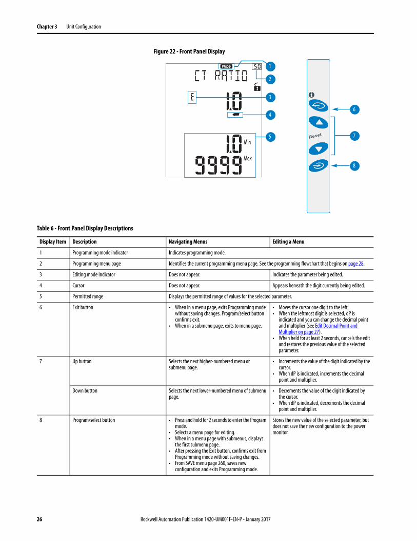
Figure 22 - Front Panel Display
6
7
8
3
4
5
2
1
Table 6 - Front Panel Display Descriptions
Display Item Description Navigating Menus Editing a Menu
1 Programming mode indicator Indicates programming mode.
2 Programming menu page Identifies the current programming menu page. See the programming flowchart that begins on page 28.
3 Editing mode indicator Does not appear. Indicates the parameter being edited.
4 Cursor Does not appear. Appears beneath the digit currently being edited.
5 Permitted range Displays the permitted range of values for the selected parameter.
6 Exit button • When in a menu page, exits Programming mode without saving changes. Program/select button confirms exit.
• When in a submenu page, exits to menu page.
• Moves the cursor one digit to the left.• When the leftmost digit is selected, dP is
indicated and you can change the decimal point and multiplier (see Edit Decimal Point and Multiplier on page 27).
• When held for at least 2 seconds, cancels the edit and restores the previous value of the selected parameter.
7 Up button Selects the next higher-numbered menu or submenu page.
• Increments the value of the digit indicated by the cursor.
• When dP is indicated, increments the decimal point and multiplier.
Down button Selects the next lower-numbered menu of submenu page.
• Decrements the value of the digit indicated by the cursor.
• When dP is indicated, decrements the decimal point and multiplier.
8 Program/select button • Press and hold for 2 seconds to enter the Program mode.
• Selects a menu page for editing.• When in a menu page with submenus, displays
the first submenu page.• After pressing the Exit button, confirms exit from
Programming mode without saving changes.• From SAVE menu page 260, saves new
configuration and exits Programming mode.
Stores the new value of the selected parameter, but does not save the new configuration to the power monitor.
26 Rockwell Automation Publication 1420-UM001F-EN-P - January 2017
Unit Configuration Chapter 3
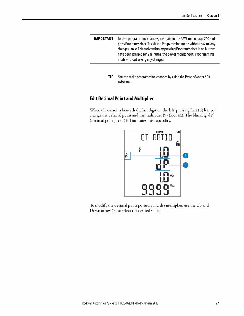
Edit Decimal Point and Multiplier
When the cursor is beneath the last digit on the left, pressing Exit (6) lets you change the decimal point and the multiplier (9) (k or M). The blinking ‘dP’ (decimal point) text (10) indicates this capability.
To modify the decimal point position and the multiplier, use the Up and Down arrow (7) to select the desired value.
IMPORTANT To save programming changes, navigate to the SAVE menu page 260 and
press Program/select. To exit the Programming mode without saving any
changes, press Exit and confirm by pressing Program/select. If no buttons
have been pressed for 2 minutes, the power monitor exits Programming
mode without saving any changes.
TIP You can make programming changes by using the PowerMonitor 500
software.
10
9
Rockwell Automation Publication 1420-UM001F-EN-P - January 2017 27
Chapter 3 Unit Configuration
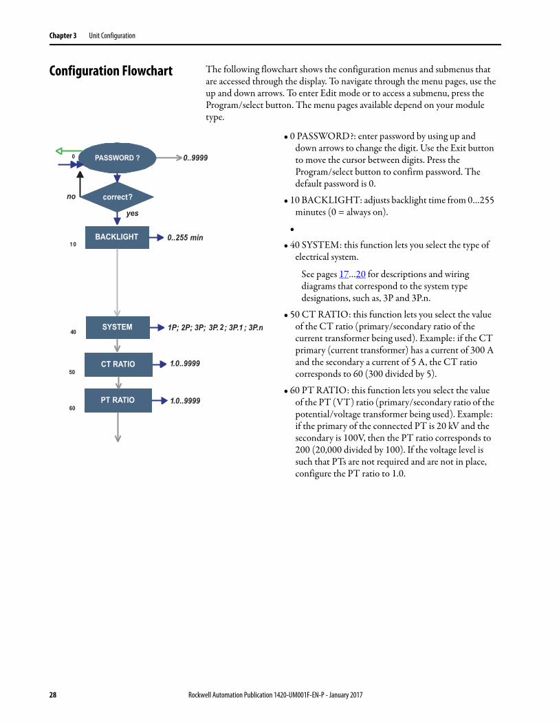
Configuration Flowchart The following flowchart shows the configuration menus and submenus that are accessed through the display. To navigate through the menu pages, use the up and down arrows. To enter Edit mode or to access a submenu, press the Program/select button. The menu pages available depend on your module type.
• 0 PASSWORD?: enter password by using up and down arrows to change the digit. Use the Exit button to move the cursor between digits. Press the Program/select button to confirm password. The default password is 0.
• 10 BACKLIGHT: adjusts backlight time from 0…255 minutes (0 = always on).
•
• 40 SYSTEM: this function lets you select the type of electrical system.
See pages 17…20 for descriptions and wiring diagrams that correspond to the system type designations, such as, 3P and 3P.n.
• 50 CT RATIO: this function lets you select the value of the CT ratio (primary/secondary ratio of the current transformer being used). Example: if the CT primary (current transformer) has a current of 300 A and the secondary a current of 5 A, the CT ratio corresponds to 60 (300 divided by 5).
• 60 PT RATIO: this function lets you select the value of the PT (VT) ratio (primary/secondary ratio of the potential/voltage transformer being used). Example: if the primary of the connected PT is 20 kV and the secondary is 100V, then the PT ratio corresponds to 200 (20,000 divided by 100). If the voltage level is such that PTs are not required and are not in place, configure the PT ratio to 1.0.
28 Rockwell Automation Publication 1420-UM001F-EN-P - January 2017

Unit Configuration Chapter 3
• 70 DMD: This function lets you select the calculation method of the DMD/AVG value of the selected variable.
– 71 TYPE: select the type of Calculation mode to be used for the DMD/AVG calculation.FIXED: The instrument calculates the AVG/DMD value of the measured variable over the selected interval, updates the AVG/DMD value at the end of the interval, then resets and starts a new calculation.SLIDE: When first configured, the instrument calculates the AVG/DMD value and updates its value at the beginning after the first selected interval. After the first interval, the instrument calculates the AVG/DMD value every minute. After the calculation, the instrument generates a window whose width is the selected interval and that moves forward every minute.
– 72 TIME: select the time interval for the DMD/AVG calculation. Default is 15 minutes.
– 73 SYNC: select the Synchronization mode. That mode is the method that controls the calculation method of the average/demand according to the selected time.
• 100 FILTER: The digital filter makes it possible to stabilize the display of fluctuating measurements.
See Digital Filtering Operation on page 33.– 101 FILTER S: set the operating range (span) of
the digital filter. The value is expressed as a % (filter to 0.0 means filter excluded).
– 102 FILTER CO: set the filtering coefficient of the instantaneous measures. By increasing the value, also the stability and the settling time of the measures are increased.
IMPORTANT: Some specific menus display only if the relevant
modules are installed.
Where:
Pmax is the maximum power
Pc is the contractual power
t1 is the selected time period for the calculation of the AVG/DMD value
Fixed
Slide
Rockwell Automation Publication 1420-UM001F-EN-P - January 2017 29
Chapter 3 Unit Configuration
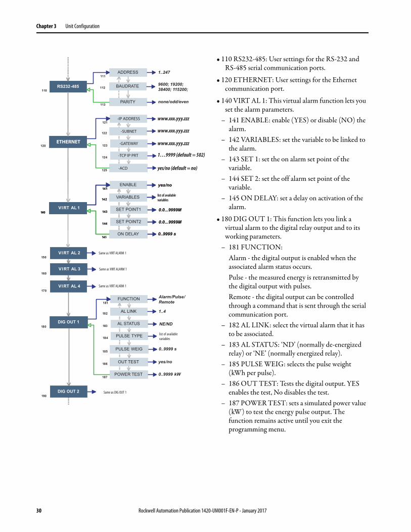
• 110 RS232-485: User settings for the RS-232 and RS-485 serial communication ports.
• 120 ETHERNET: User settings for the Ethernet communication port.
• 140 VIRT AL 1: This virtual alarm function lets you set the alarm parameters.
– 141 ENABLE: enable (YES) or disable (NO) the alarm.
– 142 VARIABLES: set the variable to be linked to the alarm.
– 143 SET 1: set the on alarm set point of the variable.
– 144 SET 2: set the off alarm set point of the variable.
– 145 ON DELAY: set a delay on activation of the alarm.
• 180 DIG OUT 1: This function lets you link a virtual alarm to the digital relay output and to its working parameters.
– 181 FUNCTION: Alarm - the digital output is enabled when the associated alarm status occurs. Pulse - the measured energy is retransmitted by the digital output with pulses. Remote - the digital output can be controlled through a command that is sent through the serial communication port.
– 182 AL LINK: select the virtual alarm that it has to be associated.
– 183 AL STATUS: ‘ND’ (normally de-energized relay) or ‘NE’ (normally energized relay).
– 185 PULSE WEIG: selects the pulse weight (kWh per pulse).
– 186 OUT TEST: Tests the digital output. YES enables the test, No disables the test.
– 187 POWER TEST: sets a simulated power value (kW) to test the energy pulse output. The function remains active until you exit the programming menu.
list of available
variables
list of available
variables
Same as DIG OUT 1
Same as VIRT ALARM 1
Same as VIRT ALARM 1
list of available
variables
-IP ADDRESS
-SUBNET
-GATEWAY
-TCP IP PRT
-ACD
ETHERNET
www.xxx.yyy.zzz
www.xxx.yyy.zzz
www.xxx.yyy.zzz
1…9999 (default = 502)
yes/no (default = no)
Same as VIRT ALARM 1
30 Rockwell Automation Publication 1420-UM001F-EN-P - January 2017
Unit Configuration Chapter 3
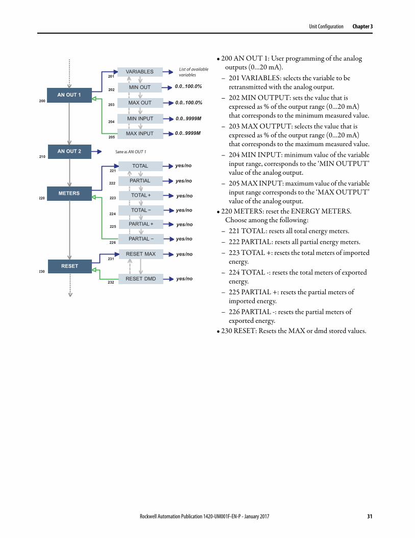
• 200 AN OUT 1: User programming of the analog outputs (0…20 mA).
– 201 VARIABLES: selects the variable to be retransmitted with the analog output.
– 202 MIN OUTPUT: sets the value that is expressed as % of the output range (0…20 mA) that corresponds to the minimum measured value.
– 203 MAX OUTPUT: selects the value that is expressed as % of the output range (0…20 mA) that corresponds to the maximum measured value.
– 204 MIN INPUT: minimum value of the variable input range, corresponds to the ‘MIN OUTPUT’ value of the analog output.
– 205 MAX INPUT: maximum value of the variable input range corresponds to the ‘MAX OUTPUT’ value of the analog output.
• 220 METERS: reset the ENERGY METERS. Choose among the following:
– 221 TOTAL: resets all total energy meters.– 222 PARTIAL: resets all partial energy meters.– 223 TOTAL +: resets the total meters of imported
energy.– 224 TOTAL -: resets the total meters of exported
energy.– 225 PARTIAL +: resets the partial meters of
imported energy.– 226 PARTIAL -: resets the partial meters of
exported energy.• 230 RESET: Resets the MAX or dmd stored values.
List of availablevariables
Same as AN OUT 1
Rockwell Automation Publication 1420-UM001F-EN-P - January 2017 31
Chapter 3 Unit Configuration
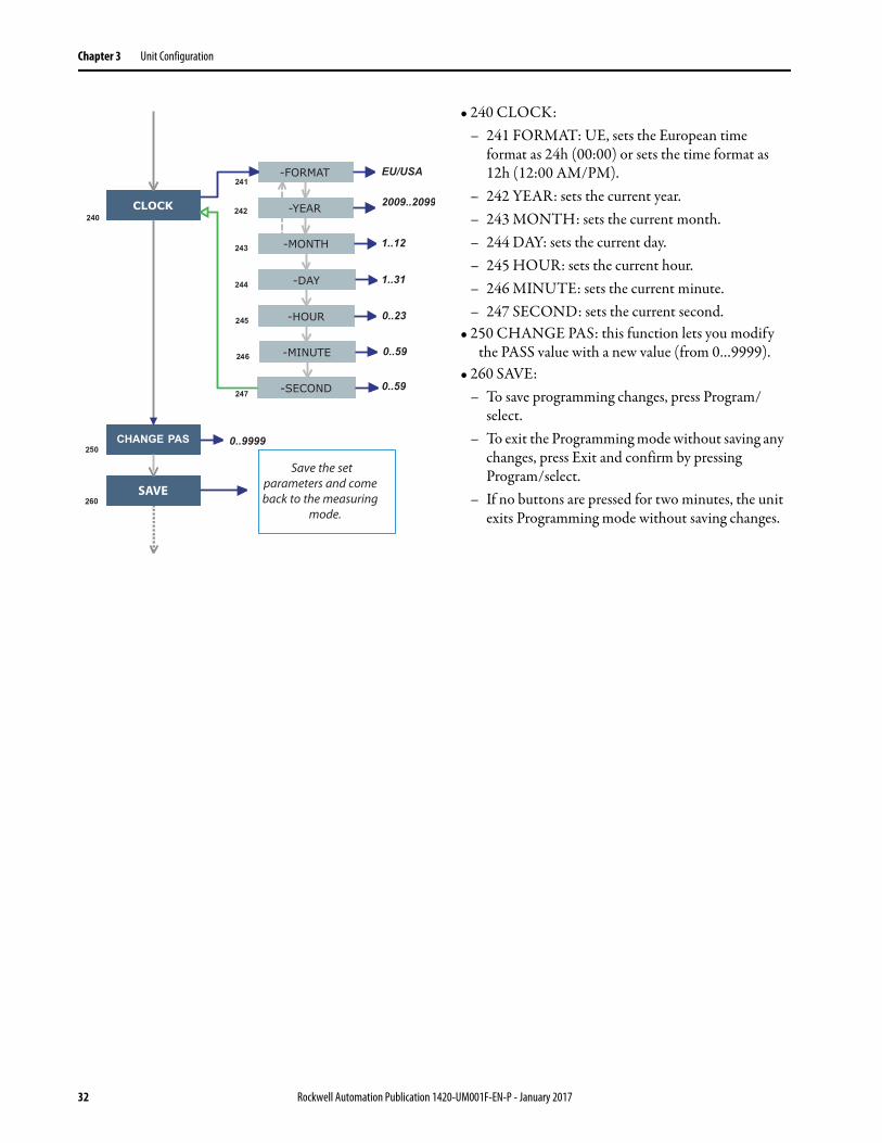
• 240 CLOCK:– 241 FORMAT: UE, sets the European time
format as 24h (00:00) or sets the time format as 12h (12:00 AM/PM).
– 242 YEAR: sets the current year.– 243 MONTH: sets the current month.– 244 DAY: sets the current day.– 245 HOUR: sets the current hour.– 246 MINUTE: sets the current minute.– 247 SECOND: sets the current second.
• 250 CHANGE PAS: this function lets you modify the PASS value with a new value (from 0…9999).
• 260 SAVE: – To save programming changes, press Program/
select. – To exit the Programming mode without saving any
changes, press Exit and confirm by pressing Program/select.
– If no buttons are pressed for two minutes, the unit exits Programming mode without saving changes.
Save the set parameters and comeback to the measuring
mode.
SAVE
32 Rockwell Automation Publication 1420-UM001F-EN-P - January 2017
Unit Configuration Chapter 3
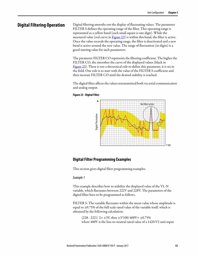
Digital Filtering Operation Digital filtering smooths out the display of fluctuating values. The parameter FILTER S defines the operating range of the filter. This operating range is represented as a yellow band (each small square is one digit). While the measured value (red curve in Figure 23) is within this band, the filter is active. Once the value exceeds the operating range, the filter is deactivated and a new band is active around the new value. The range of fluctuation (in digits) is a good starting value for such parameters.
The parameter FILTER CO represents the filtering coefficient. The higher the FILTER CO, the smoother the curve of the displayed values (black in Figure 23). There is not a theoretical rule to define this parameter, it is set in the field. One rule is to start with the value of the FILTER S coefficient and then increase FILTER CO until the desired stability is reached.
The digital filter affects the values retransmitted both via serial communication and analog output.
Figure 23 - Digital Filter
Digital Filter Programming Examples
This section gives digital filter programming examples.
Example 1
This example describes how to stabilize the displayed value of the VL-N variable, which fluctuates between 222V and 228V. The parameters of the digital filter have to be programmed as follows.
FILTER S: The variable fluctuates within the mean value whose amplitude is equal to ±0.75% of the full scale rated value of the variable itself, which is obtained by the following calculation:
(228 - 222)/ 2= ±3V, then ±3*100/400V= ±0.75% where 400V is the line-to-neutral rated value of a 1420-V2 unit input
No filter action
Dig
ital F
luct
uatio
n
Rockwell Automation Publication 1420-UM001F-EN-P - January 2017 33
Chapter 3 Unit Configuration
The FILTER S parameter, which represents the action range of the digital filter, is programmed to a value that must be slightly higher than the percentage amplitude of the fluctuation, for example, 1.0%.
FILTER CO: if the new value that is measured by the instrument is within the action range of the filter, the new displayed value is obtained by adding algebraically the previous value to the variation divided by the filtering coefficient. As a consequence, a value higher than this coefficient implies a longer settling time and therefore better stability. You generally obtain the best result by setting the filtering coefficient to a value equal to at least 10 times the range parameter value.
In the following example, 1.0*10=10, the stability of the filtering coefficient can be improved by increasing the filtering coefficient; the allowed values are included within 1 and 255.
Example 2
This example describes how to stabilize the value of the displayed System Real Power (W), which fluctuates 300...320 kW. In this example, the load is connected to the instrument with a 300/5 A CT and a direct measure of the voltage.
The parameters of the digital filter must be programmed as follows.
FILTER S: the variable fluctuates within the mean value whose amplitude is equal to ±2.78% of the full scale rated value of this variable. This value is obtained by the following calculation:
(320 - 300)/ 2= ±10 kW, then ±10*100/360 kW= ±2.78%,
where 360 kW is the rated value of the System Real Power of a 1420-V2 unit input, at the CT and VT ratios and obtained with the following formula:
VLN * VT * IN * CT * 3
Where:
VLN = rated input voltage (400V for the V1 input)
VT= primary/secondary ratio of the voltage transformer being used
IN = rated current (5 A)
CT = primary/secondary ratio of the voltage transformer being used (in this example 400*1*5*60*3=360 kW).
The FILTER S parameter, which represents the digital filtering coefficient action range, is programmed to a value that must be slightly higher than the percentage of the fluctuation: for example 3.0%.
34 Rockwell Automation Publication 1420-UM001F-EN-P - January 2017
Unit Configuration Chapter 3
FILTER CO: if the new value that is acquired by the unit is within the filtering action range, the new displayed value is obtained by adding algebraically the previous value to the variation divided by the filtering coefficient. As a consequence, a value higher than this coefficient implies a higher settling time and therefore better stability. Therefore, the best result is obtained by setting the filtering coefficient to a value equal to at least 10 times the value of the range parameters. In the example, 3.0*10=30. To improve the stability, you can increase the filtering coefficient; the admitted values are included within 1 and 255.
Example 3
It is necessary to stabilize the value of the displayed variable A L1 (phase current 1), which fluctuates in the range 470 A and 486 A.
To be able to manage the alarm function and activation and deactivation of the relay, this value is not to be subject to continuous fluctuations. In this example, we have considered using a 500/5 A CT. Program the parameters of the digital filter as follows:
FILTER S: the variable fluctuates within the mean value whose amplitude is equal to ±1.60% of the full scale rated value of this variable (obtained with the calculation:
(486 - 470)/ 2= ±8 A, then ±8*100/500 A= ±1.60% where 500 A is the value referred to the primary of the transformer being used).
The FILTER S parameter, which represents the action range of the digital filter, is programmed to a value slightly higher than the percentage amplitude of the fluctuation, for example 2.0%.
FILTER CO: if the new value that is acquired by the instrument is within the filtering action range, the new displayed value is calculated algebraically adding to the previous value the variation divided by the filtering coefficient. As a consequence, a higher value of this coefficient implies a higher settling time and therefore better stability. Therefore, the best result is obtained setting the filtering coefficient at a value equal to at least 10 times the value of the range parameter. In the example, 2.0*10=20. To improve the stability, you can increase the filtering coefficient; the admitted values are within 1 and 255.
Rockwell Automation Publication 1420-UM001F-EN-P - January 2017 35
Chapter 3 Unit Configuration
Analog Output Configuration Examples
These examples apply to units with catalog numbers 1420-V1A and 1420-V2A.
Example 1: Power value retransmission with a 0…20 mA analog output.
This example describes how to retransmit measured power up to 100 kW with a 4…20 mA signal. Program the unit as follows:
• VARIABLE: WΣ (system real power)• MIN OUT: 20.0% means 4 mA. The calculation that is used is the
following: (100*minimum output) / full scale output =100*4 mA/ 20 mA=20%
• MAX OUT: 100.0% means 20 mA. The calculation is the following: (100*maximum output)/full scale output = 100*20 mA/20 mA= 100
• MIN INPUT: 0.0 k; the multiplier k, M, G can be selected on the unit according to the chosen VT and CT values
• MAX INPUT: 100.0 k; the k, M, G multipliers can be selected on the unit according to the selected VT and CT values
Example 2: Retransmission of the power factor (PF) value with the 0…20 mA analog output.
In this example, the unit is configured to retransmit the whole range of the allowed values for the PF with a signal from 0…20 mA. The value of the PF variable can vary between C0.001 and L0.000 (for each phase); these values, when retransmitted, correspond to 0 mA and 20 mA. When the PF value is equal to 1, the analog output value corresponds to the middle of the scale, which is 10 mA. Program the instrument as follows:
• VARIABLE: PF L1 (or L2 or L3 or PFΣ)• MIN OUT: 0.0%• MAX OUT: 100.0%• MIN INPUT: C0.001 (the C symbol shows a CAPACITIVE value)• MAX INPUT: L0.001 (the L symbol shows an INDUCTIVE value).
L0.001 has been chosen as minimum value to be set to avoid undesirable rapid changes of the outputs
36 Rockwell Automation Publication 1420-UM001F-EN-P - January 2017
Unit Configuration Chapter 3
Alarm Configuration Example
These examples apply to units with catalog numbers 1420-V1P and 1420-V2P.
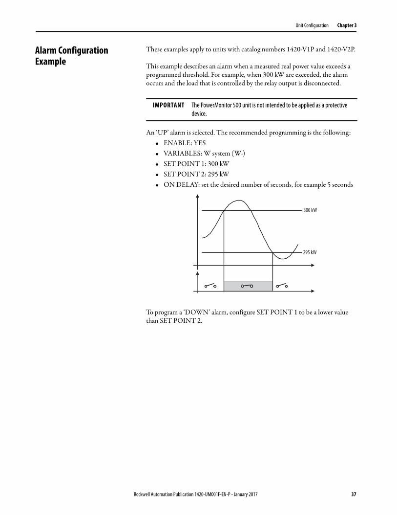
This example describes an alarm when a measured real power value exceeds a programmed threshold. For example, when 300 kW are exceeded, the alarm occurs and the load that is controlled by the relay output is disconnected.
An ‘UP’ alarm is selected. The recommended programming is the following:• ENABLE: YES• VARIABLES: W system (W·)• SET POINT 1: 300 kW• SET POINT 2: 295 kW• ON DELAY: set the desired number of seconds, for example 5 seconds
To program a ‘DOWN’ alarm, configure SET POINT 1 to be a lower value than SET POINT 2.
IMPORTANT The PowerMonitor 500 unit is not intended to be applied as a protective
device.
300 kW
295 kW
Rockwell Automation Publication 1420-UM001F-EN-P - January 2017 37

Chapter 3 Unit Configuration
Notes:
38 Rockwell Automation Publication 1420-UM001F-EN-P - January 2017
Chapter 4
Communication
EtherNet/IP Communication EtherNet/IP communication is supported in PowerMonitor™ 500 units that are ordered with optional Ethernet communication. Communication parameters in the power monitor must be configured. See Unit Configuration on page 25. The Ethernet communication port supports 100 or 10 Mbps data rate, half-duplex, or full-duplex.
The PowerMonitor 500 unit provides nine Assembly Instances that contain real-time, maximum, demand, energy, and status data that can be read by a client by using implicit messaging (Class 1) or Explicit Messaging (Class 3 or UCMM).
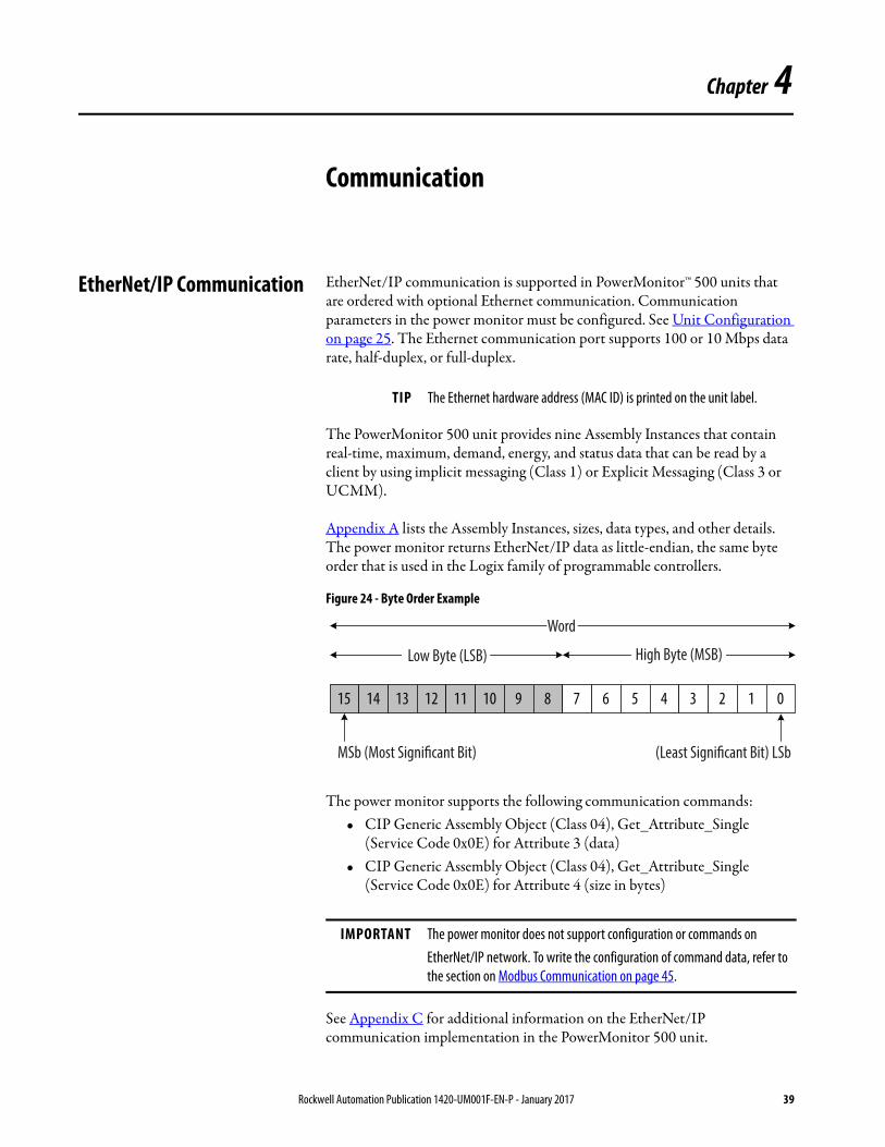
Appendix A lists the Assembly Instances, sizes, data types, and other details. The power monitor returns EtherNet/IP data as little-endian, the same byte order that is used in the Logix family of programmable controllers.
Figure 24 - Byte Order Example
The power monitor supports the following communication commands:• CIP Generic Assembly Object (Class 04), Get_Attribute_Single
(Service Code 0x0E) for Attribute 3 (data)• CIP Generic Assembly Object (Class 04), Get_Attribute_Single
(Service Code 0x0E) for Attribute 4 (size in bytes)
See Appendix C for additional information on the EtherNet/IP communication implementation in the PowerMonitor 500 unit.
TIP The Ethernet hardware address (MAC ID) is printed on the unit label.
IMPORTANT The power monitor does not support configuration or commands on
EtherNet/IP network. To write the configuration of command data, refer to
the section on Modbus Communication on page 45.
15 14 13 12 11 10 9 8 7 6 5 4 3 2 1 0
MSb (Most Significant Bit) (Least Significant Bit) LSb
Word
Low Byte (LSB) High Byte (MSB)
Rockwell Automation Publication 1420-UM001F-EN-P - January 2017 39

Chapter 4 Communication
Electronic Data Sheet (EDS)
The EDS file is used to convey device configuration data that is provided by the manufacturer. You can obtain EDS files for the PowerMonitor 500 unit by downloading the file from the following website:
http://compatibility.rockwellautomation.com/Pages/MultiProductDownload.aspx
You can install EDS files on your computer by using the EDS Hardware Installation Tool that comes with RSLinx® Classic software, RSNetWorx™ for EtherNet/IP software, or other tools.
Explicit Messaging - Message Setup with CIP Generic
The following example shows how to configure your message instruction to read from a data table in the power monitor by using a CIP Generic message type for the Studio 5000 Logix Designer® application. This setup applies to ControlLogix® and CompactLogix™ programmable logic controllers. The CIP Generic message type does not support single element reads or writes. In this example, we read the Real-time Metering Values (Voltage and Current) data table from the power monitor.
40 Rockwell Automation Publication 1420-UM001F-EN-P - January 2017
Communication Chapter 4
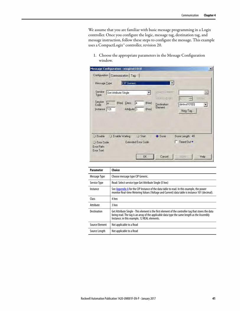
We assume that you are familiar with basic message programming in a Logix controller. Once you configure the logic, message tag, destination tag, and message instruction, follow these steps to configure the message. This example uses a CompactLogix™ controller, revision 20.
1. Choose the appropriate parameters in the Message Configuration window.
Parameter Choice
Message Type Choose message type CIP Generic.
Service Type Read: Select service type Get Attribute Single (E hex)
Instance See Appendix A for the CIP Instance of the data table to read. In this example, the power monitor Real-time Metering Values (Voltage and Current) data table is instance 101 (decimal).
Class 4 hex
Attribute 3 hex
Destination Get Attribute Single - This element is the first element of the controller tag that stores the data being read. The tag is an array of the applicable data type the same length as the Assembly Instance; in this example, 12 REAL elements.
Source Element Not applicable to a Read
Source Length Not applicable to a Read
Rockwell Automation Publication 1420-UM001F-EN-P - January 2017 41
Chapter 4 Communication
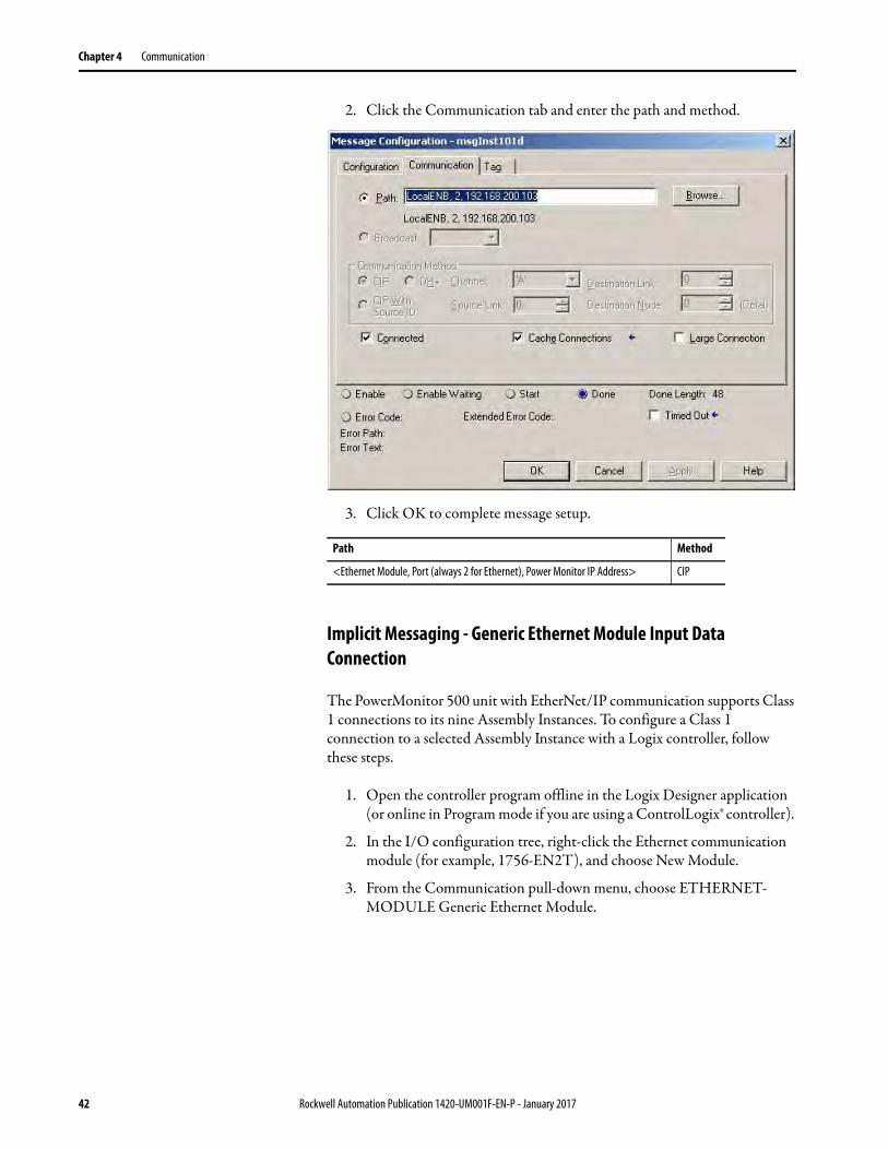
2. Click the Communication tab and enter the path and method.
3. Click OK to complete message setup.
Implicit Messaging - Generic Ethernet Module Input Data Connection
The PowerMonitor 500 unit with EtherNet/IP communication supports Class 1 connections to its nine Assembly Instances. To configure a Class 1 connection to a selected Assembly Instance with a Logix controller, follow these steps.
1. Open the controller program offline in the Logix Designer application (or online in Program mode if you are using a ControlLogix® controller).
2. In the I/O configuration tree, right-click the Ethernet communication module (for example, 1756-EN2T), and choose New Module.
3. From the Communication pull-down menu, choose ETHERNET-MODULE Generic Ethernet Module.
Path Method
<Ethernet Module, Port (always 2 for Ethernet), Power Monitor IP Address> CIP
42 Rockwell Automation Publication 1420-UM001F-EN-P - January 2017
Communication Chapter 4
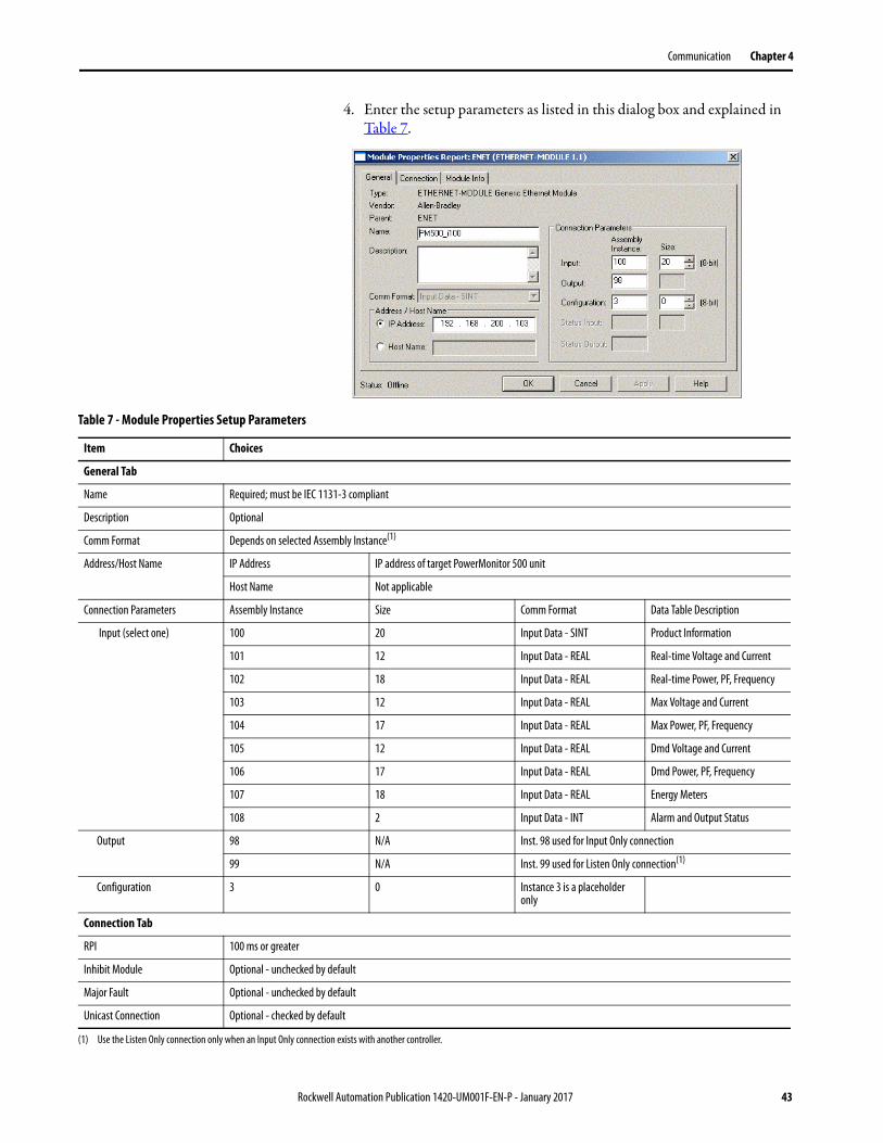
4. Enter the setup parameters as listed in this dialog box and explained in Table 7.
Table 7 - Module Properties Setup Parameters
Item Choices
General Tab
Name Required; must be IEC 1131-3 compliant
Description Optional
Comm Format Depends on selected Assembly Instance(1)
Address/Host Name IP Address IP address of target PowerMonitor 500 unit
Host Name Not applicable
Connection Parameters Assembly Instance Size Comm Format Data Table Description
Input (select one) 100 20 Input Data - SINT Product Information
101 12 Input Data - REAL Real-time Voltage and Current
102 18 Input Data - REAL Real-time Power, PF, Frequency
103 12 Input Data - REAL Max Voltage and Current
104 17 Input Data - REAL Max Power, PF, Frequency
105 12 Input Data - REAL Dmd Voltage and Current
106 17 Input Data - REAL Dmd Power, PF, Frequency
107 18 Input Data - REAL Energy Meters
108 2 Input Data - INT Alarm and Output Status
Output 98 N/A Inst. 98 used for Input Only connection
99 N/A Inst. 99 used for Listen Only connection(1)
Configuration 3 0 Instance 3 is a placeholder only
Connection Tab
RPI 100 ms or greater
Inhibit Module Optional - unchecked by default
Major Fault Optional - unchecked by default
Unicast Connection Optional - checked by default
(1) Use the Listen Only connection only when an Input Only connection exists with another controller.
Rockwell Automation Publication 1420-UM001F-EN-P - January 2017 43
Chapter 4 Communication
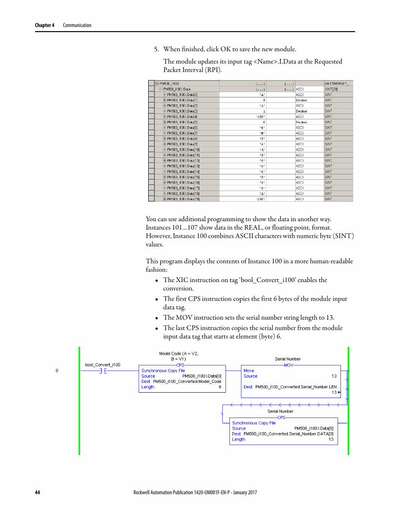
5. When finished, click OK to save the new module.
The module updates its input tag <Name>.I.Data at the Requested Packet Interval (RPI).
You can use additional programming to show the data in another way. Instances 101…107 show data in the REAL, or floating point, format. However, Instance 100 combines ASCII characters with numeric byte (SINT) values.
This program displays the contents of Instance 100 in a more human-readable fashion:
• The XIC instruction on tag ‘bool_Convert_i100’ enables the conversion.
• The first CPS instruction copies the first 6 bytes of the module input data tag.
• The MOV instruction sets the serial number string length to 13. • The last CPS instruction copies the serial number from the module
input data tag that starts at element (byte) 6.
44 Rockwell Automation Publication 1420-UM001F-EN-P - January 2017
Communication Chapter 4
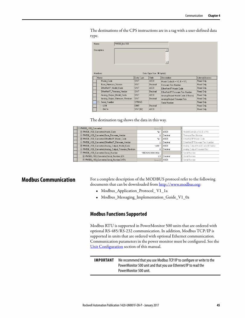
The destinations of the CPS instructions are in a tag with a user-defined data type.
The destination tag shows the data in this way.
Modbus Communication For a complete description of the MODBUS protocol refer to the following documents that can be downloaded from http://www.modbus.org:
• Modbus_Application_Protocol_ V1_1a• Modbus_Messaging_Implementation_Guide_V1_0a
Modbus Functions Supported
Modbus RTU is supported in PowerMonitor 500 units that are ordered with optional RS-485/RS-232 communication. In addition, Modbus TCP/IP is supported in units that are ordered with optional Ethernet communication. Communication parameters in the power monitor must be configured. See the Unit Configuration section of this manual.
IMPORTANT We recommend that you use Modbus TCP/IP to configure or write to the
PowerMonitor 500 unit and that you use Ethernet/IP to read the
PowerMonitor 500 unit.
Rockwell Automation Publication 1420-UM001F-EN-P - January 2017 45
Chapter 4 Communication
The PowerMonitor 500 unit supports the following Modbus functions:• 0x03 - Read n Holding Registers• 0x04 - Read n Input Register• 0x06 - Write one Holding Register• 0x10 - Write multiple registers• 0x08 - Diagnostic (with subfunction code 0x00)• 0x42 - Read n Special Registers (vendor specific)• Broadcast mode (write command on address 00h)
In this section, Modbus addresses are indicated in two ways. The ‘Modbus address’ is expressed as the 6-digit input register address (example: 300123), used with Modbus function code 0x04. The ‘Physical address’ is the hexadecimal representation of the word address that is included in the communication frame.
Modbus function 0x04 can be used with the Modbus address by substituting a 4 for the first digit (example: 400123). With that distinction, functions 0x03 and 0x04 return the same data.
To avoid errors due to signal reflections or line coupling, a termination resistor must be connected at the RS-485 ports of the master station and of the furthest power monitor from the master station. In the PowerMonitor 500, you can implement a jumper between (B+) and (T) to apply the required termination resistance between (A-) and (B+) internally. Termination on both ends is necessary even in case of point-to-point connection, with short distances.
The GND connection is optional if a shielded cable is used. For connections longer than 1000 m (3280 ft), a line amplifier is necessary.
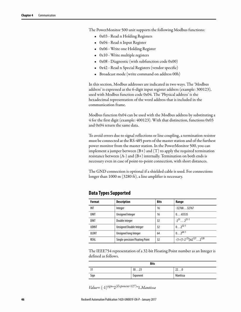
Data Types Supported
The IEEE754 representation of a 32-bit Floating Point number as an Integer is defined as follows.
Value= (-1)sign*2(Exponent-127)*1.Mantissa
Format Description Bits Range
INT Integer 16 -32768…32767
UNIT Unsigned Integer 16 0… 65535
DINT Double integer 32 -231… 231-1
UDINT Unsigned Double Integer 32 0…232-1
ULINT Unsigned long Integer 64 0…264-1
REAL Single-precision Floating Point 32 -(1+[1-2-23])x2127…2128
Bits
31 30…23 22…0
Sign Exponent Mantissa
46 Rockwell Automation Publication 1420-UM001F-EN-P - January 2017
Communication Chapter 4
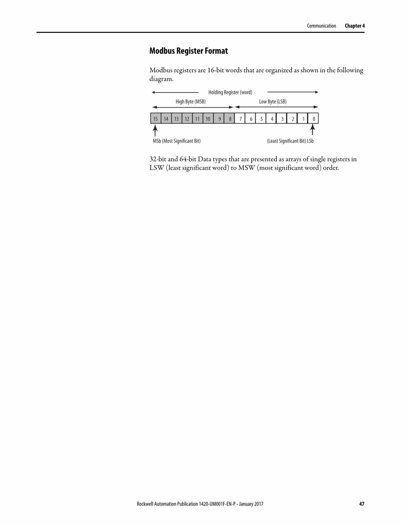
Modbus Register Format
Modbus registers are 16-bit words that are organized as shown in the following diagram.
32-bit and 64-bit Data types that are presented as arrays of single registers in LSW (least significant word) to MSW (most significant word) order.
15 14 13 12 11 10 9 8 7 6 5 4 3 2 1 0
MSb (Most Significant Bit) (Least Significant Bit) LSb
High Byte (MSB) Low Byte (LSB)
Holding Register (word)
Rockwell Automation Publication 1420-UM001F-EN-P - January 2017 47

Chapter 4 Communication
Notes:
48 Rockwell Automation Publication 1420-UM001F-EN-P - January 2017
Appendix A
PowerMonitor 500 Unit Data Tables
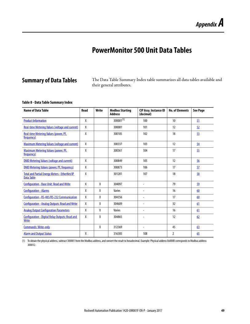
Summary of Data Tables The Data Table Summary Index table summarizes all data tables available and their general attributes.
Table 8 - Data Table Summary Index
Name of Data Table Read Write Modbus Starting Address
CIP Assy. Instance ID (decimal)
No. of Elements See Page
Product Information X 300001(1) 100 10 51
Real-time Metering Values (voltage and current) X 300081 101 12 52
Real-time Metering Values (power, PF, frequency)
X 300105 102 18 53
Maximum Metering Values (voltage and current) X 300337 103 12 54
Maximum Metering Values (power, PF, frequency)
X 300361 104 17 55
DMD Metering Values (voltage and current) X 300849 105 12 56
DMD Metering Values (power, PF, frequency) X 300873 106 17 57
Total and Partial Energy Meters - EtherNet/IP Data Table
X 301281 107 18 58
Configuration - Base Unit: Read and Write X X 304097 - 79 59
Configuration - Alarms X X Varies - 16 60
Configuration - RS-485/RS-232 Communication X X 304356 - 17 60
Configuration - Analog Outputs: Read and Write X X 304609 - 32 61
Analog Output Configuration Parameters X X Varies - 16 61
Configuration - Digital Relay Outputs: Read and Write
X X 304865 - 12 62
Commands: Write-only X 312369 - 45 63
Alarm and Output Status X 316385 108 2 65
(1) To obtain the physical address, subtract 300001 from the Modbus address, and convert the result to hexadecimal. Example: Physical address 0x000B corresponds to Modbus address
300012.
Rockwell Automation Publication 1420-UM001F-EN-P - January 2017 49
Appendix A PowerMonitor 500 Unit Data Tables
Geometric Representation of Power and Power Factor
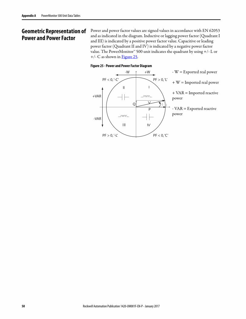
Power and power factor values are signed values in accordance with EN 62053 and as indicated in the diagram. Inductive or lagging power factor (Quadrant I and III) is indicated by a positive power factor value. Capacitive or leading power factor (Quadrant II and IV) is indicated by a negative power factor value. The PowerMonitor™ 500 unit indicates the quadrant by using +/- L or +/- C as shown in Figure 25.
Figure 25 - Power and Power Factor Diagram
-W +W
Q
P
+VAR
-VAR
PF > 0, ‘-L’ PF < 0, ‘C’
PF > 0, ‘L’PF < 0, ‘-C’
- W = Exported real power
+ W = Imported real power
+ VAR = Imported reactive power
- VAR = Exported reactive power
50 Rockwell Automation Publication 1420-UM001F-EN-P - January 2017
PowerMonitor 500 Unit Data Tables Appendix A
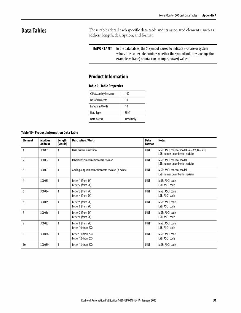
Data Tables These tables detail each specific data table and its associated elements, such as address, length, description, and format.
Product Information
IMPORTANT In the data tables, the symbol is used to indicate 3-phase or system
values. The context determines whether the symbol indicates average (for
example, voltage) or total (for example, power) values.
Table 9 - Table Properties
CIP Assembly Instance 100
No. of Elements 10
Length in Words 10
Data Type UINT
Data Access Read Only
Table 10 - Product Information Data Table
Element Modbus Address
Length (words)
Description / Units Data Format
Notes
1 300001 1 Base firmware revision UINT MSB: ASCII code for model (A = V2, B = V1) LSB: numeric number for revision
2 300002 1 EtherNet/IP module firmware revision UINT MSB: ASCII code for modelLSB: numeric number for revision
3 300003 1 Analog output module firmware revision (if exists) UINT MSB: ASCII code for model
LSB: numeric number for revision
4 300033 1 Letter 1 (from SX)
Letter 2 (from SX)
UINT MSB: ASCII code
LSB: ASCII code
5 300034 1 Letter 3 (from SX)
Letter 4 (from SX)
UINT MSB: ASCII code
LSB: ASCII code
6 300035 1 Letter 5 (from SX)
Letter 6 (from SX)
UINT MSB: ASCII code
LSB: ASCII code
7 300036 1 Letter 7 (from SX)
Letter 8 (from SX)
UINT MSB: ASCII code
LSB: ASCII code
8 300037 1 Letter 9 (from SX)
Letter 10 (from SX)
UINT MSB: ASCII code
LSB: ASCII code
9 300038 1 Letter 11 (from SX)
Letter 12 (from SX)
UINT MSB: ASCII code
LSB: ASCII code
10 300039 1 Letter 13 (from SX) UINT MSB: ASCII code
Rockwell Automation Publication 1420-UM001F-EN-P - January 2017 51
Appendix A PowerMonitor 500 Unit Data Tables
Real-time Metering Values (voltage and current)
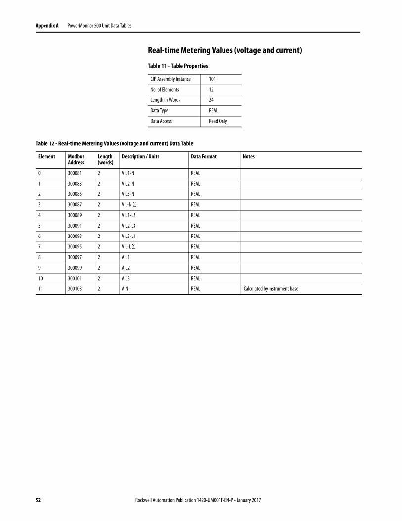
Table 11 - Table Properties
CIP Assembly Instance 101
No. of Elements 12
Length in Words 24
Data Type REAL
Data Access Read Only
Table 12 - Real-time Metering Values (voltage and current) Data Table
Element Modbus Address
Length (words)
Description / Units Data Format Notes
0 300081 2 V L1-N REAL
1 300083 2 V L2-N REAL
2 300085 2 V L3-N REAL
3 300087 2 V L-N REAL
4 300089 2 V L1-L2 REAL
5 300091 2 V L2-L3 REAL
6 300093 2 V L3-L1 REAL
7 300095 2 V L-L REAL
8 300097 2 A L1 REAL
9 300099 2 A L2 REAL
10 300101 2 A L3 REAL
11 300103 2 A N REAL Calculated by instrument base
52 Rockwell Automation Publication 1420-UM001F-EN-P - January 2017
PowerMonitor 500 Unit Data Tables Appendix A
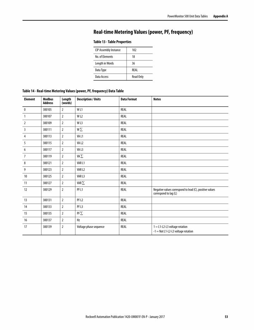
Real-time Metering Values (power, PF, frequency)
Table 13 - Table Properties
CIP Assembly Instance 102
No. of Elements 18
Length in Words 36
Data Type REAL
Data Access Read Only
Table 14 - Real-time Metering Values (power, PF, frequency) Data Table
Element Modbus Address
Length (words)
Description / Units Data Format Notes
0 300105 2 W L1 REAL
1 300107 2 W L2 REAL
2 300109 2 W L3 REAL
3 300111 2 W REAL
4 300113 2 VA L1 REAL
5 300115 2 VA L2 REAL
6 300117 2 VA L3 REAL
7 300119 2 VA REAL
8 300121 2 VAR L1 REAL
9 300123 2 VAR L2 REAL
10 300125 2 VAR L3 REAL
11 300127 2 VAR REAL
12 300129 2 PF L1 REAL Negative values correspond to lead (C), positive values correspond to lag (L)
13 300131 2 PF L2 REAL
14 300133 2 PF L3 REAL
15 300135 2 PF REAL
16 300137 2 Hz REAL
17 300139 2 Voltage phase sequence REAL 1 = L1-L2-L3 voltage rotation
-1 = Not L1-L2-L3 voltage rotation
Rockwell Automation Publication 1420-UM001F-EN-P - January 2017 53
Appendix A PowerMonitor 500 Unit Data Tables
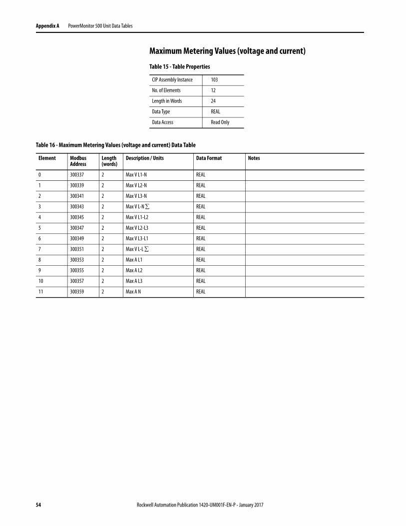
Maximum Metering Values (voltage and current)
Table 15 - Table Properties
CIP Assembly Instance 103
No. of Elements 12
Length in Words 24
Data Type REAL
Data Access Read Only
Table 16 - Maximum Metering Values (voltage and current) Data Table
Element Modbus Address
Length (words)
Description / Units Data Format Notes
0 300337 2 Max V L1-N REAL
1 300339 2 Max V L2-N REAL
2 300341 2 Max V L3-N REAL
3 300343 2 Max V L-N REAL
4 300345 2 Max V L1-L2 REAL
5 300347 2 Max V L2-L3 REAL
6 300349 2 Max V L3-L1 REAL
7 300351 2 Max V L-L REAL
8 300353 2 Max A L1 REAL
9 300355 2 Max A L2 REAL
10 300357 2 Max A L3 REAL
11 300359 2 Max A N REAL
54 Rockwell Automation Publication 1420-UM001F-EN-P - January 2017

PowerMonitor 500 Unit Data Tables Appendix A
Maximum Metering Values (power, PF, frequency)
Table 17 - Table Properties
CIP Assembly Instance 104
No. of Elements 17
Length in Words 34
Data Type REAL
Data Access Read Only
Table 18 - Maximum Metering Values (power, PF, frequency) Data Table
Element Modbus Address
Length (words)
Description / Units Data Format Notes
0 300361 2 Max W L1 REAL
1 300363 2 Max W L2 REAL
2 300365 2 Max W L3 REAL
3 300367 2 Max W 3 REAL
4 300369 2 Max VA L1 REAL
5 300371 2 Max VA L2 REAL
6 300373 2 Max VA L3 REAL
7 300375 2 Max VA REAL
8 300377 2 Max VAR L1 REAL Negative values correspond to lead (C), positive values correspond to lag (L)
9 300379 2 Max VAR L2 REAL
10 300381 2 Max VAR L3 REAL
11 300383 2 Max VAR REAL
12 300385 2 Max PF L1 REAL The Max PF displayed corresponds to the PF value with the largest phase angle.
13 300387 2 Max PF L2 REAL
14 300389 2 Max PF L3 REAL
15 300391 2 Max PF REAL
16 300393 2 Max Hz REAL
Rockwell Automation Publication 1420-UM001F-EN-P - January 2017 55
Appendix A PowerMonitor 500 Unit Data Tables
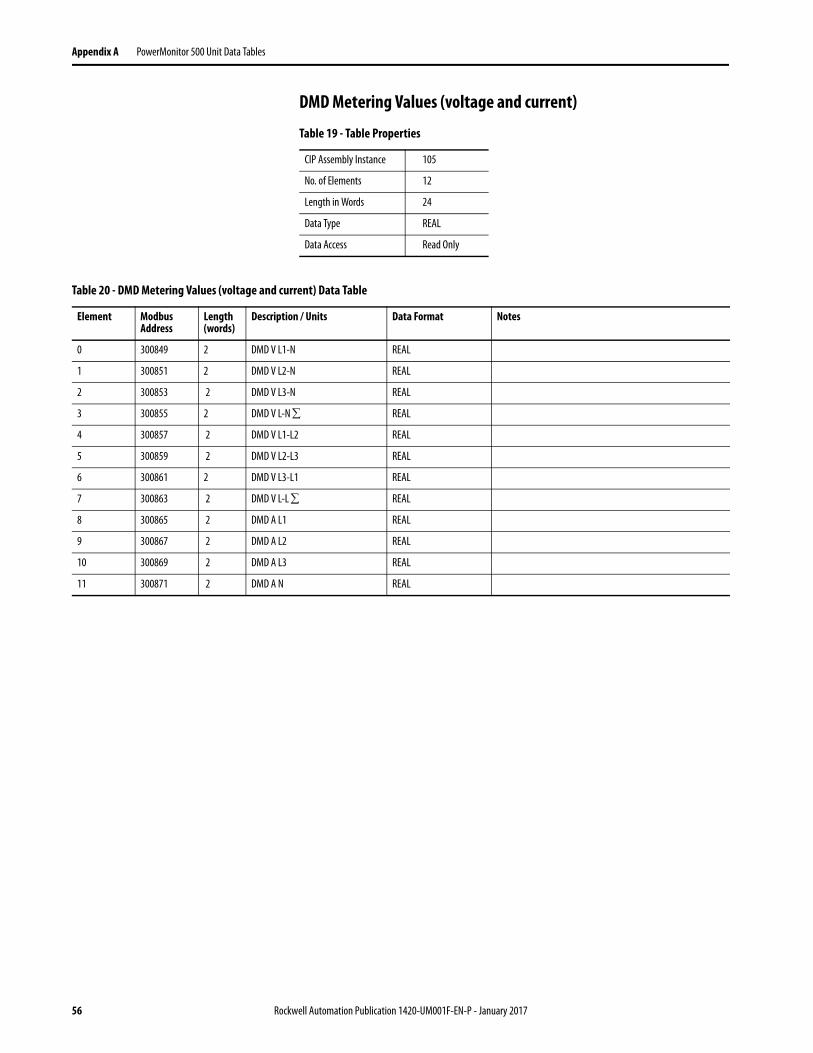
DMD Metering Values (voltage and current)
Table 19 - Table Properties
CIP Assembly Instance 105
No. of Elements 12
Length in Words 24
Data Type REAL
Data Access Read Only
Table 20 - DMD Metering Values (voltage and current) Data Table
Element Modbus Address
Length (words)
Description / Units Data Format Notes
0 300849 2 DMD V L1-N REAL
1 300851 2 DMD V L2-N REAL
2 300853 2 DMD V L3-N REAL
3 300855 2 DMD V L-N REAL
4 300857 2 DMD V L1-L2 REAL
5 300859 2 DMD V L2-L3 REAL
6 300861 2 DMD V L3-L1 REAL
7 300863 2 DMD V L-L REAL
8 300865 2 DMD A L1 REAL
9 300867 2 DMD A L2 REAL
10 300869 2 DMD A L3 REAL
11 300871 2 DMD A N REAL
56 Rockwell Automation Publication 1420-UM001F-EN-P - January 2017
PowerMonitor 500 Unit Data Tables Appendix A
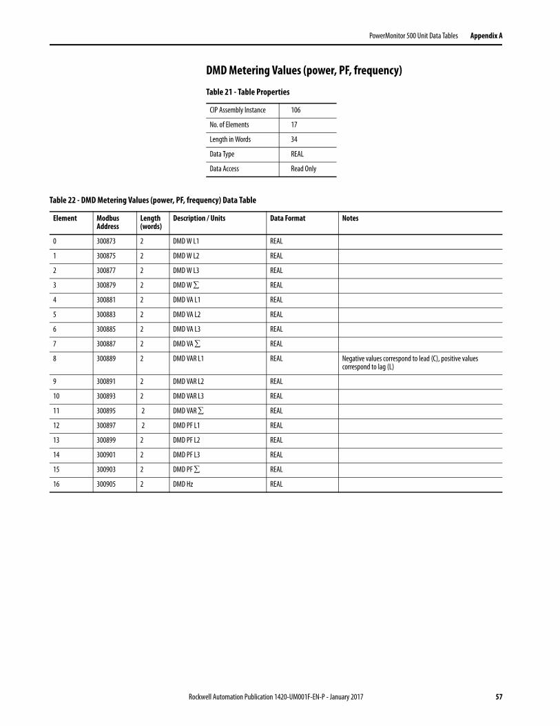
DMD Metering Values (power, PF, frequency)
Table 21 - Table Properties
CIP Assembly Instance 106
No. of Elements 17
Length in Words 34
Data Type REAL
Data Access Read Only
Table 22 - DMD Metering Values (power, PF, frequency) Data Table
Element Modbus Address
Length (words)
Description / Units Data Format Notes
0 300873 2 DMD W L1 REAL
1 300875 2 DMD W L2 REAL
2 300877 2 DMD W L3 REAL
3 300879 2 DMD W REAL
4 300881 2 DMD VA L1 REAL
5 300883 2 DMD VA L2 REAL
6 300885 2 DMD VA L3 REAL
7 300887 2 DMD VA REAL
8 300889 2 DMD VAR L1 REAL Negative values correspond to lead (C), positive values correspond to lag (L)
9 300891 2 DMD VAR L2 REAL
10 300893 2 DMD VAR L3 REAL
11 300895 2 DMD VAR REAL
12 300897 2 DMD PF L1 REAL
13 300899 2 DMD PF L2 REAL
14 300901 2 DMD PF L3 REAL
15 300903 2 DMD PF REAL
16 300905 2 DMD Hz REAL
Rockwell Automation Publication 1420-UM001F-EN-P - January 2017 57
Appendix A PowerMonitor 500 Unit Data Tables
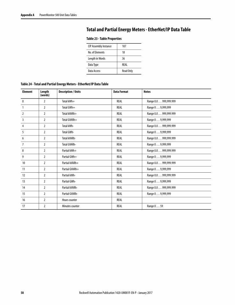
Total and Partial Energy Meters - EtherNet/IP Data Table
Table 23 - Table Properties
CIP Assembly Instance 107
No. of Elements 18
Length in Words 36
Data Type REAL
Data Access Read Only
Table 24 - Total and Partial Energy Meters - EtherNet/IP Data Table
Element Length (words)
Description / Units Data Format Notes
0 2 Total kWh+ REAL Range 0.0 … 999,999.999
1 2 Total GWh+ REAL Range 0 … 9,999,999
2 2 Total kVARh+ REAL Range 0.0 … 999,999.999
3 2 Total GVARh+ REAL Range 0 … 9,999,999
4 2 Total kWh- REAL Range 0.0 … 999,999.999
5 2 Total GWh- REAL Range 0 … 9,999,999
6 2 Total kVARh- REAL Range 0.0 … 999,999.999
7 2 Total GVARh- REAL Range 0 … 9,999,999
8 2 Partial kWh+ REAL Range 0.0 … 999,999.999
9 2 Partial GWh+ REAL Range 0 … 9,999,999
10 2 Partial kVARh+ REAL Range 0.0 … 999,999.999
11 2 Partial GVARh+ REAL Range 0 … 9,999,999
12 2 Partial kWh- REAL Range 0.0 … 999,999.999
13 2 Partial GWh- REAL Range 0 … 9,999,999
14 2 Partial kVARh- REAL Range 0.0 … 999,999.999
15 2 Partial GVARh- REAL Range 0 … 9,999,999
16 2 Hours counter REAL
17 2 Minutes counter REAL Range 0 … 59
58 Rockwell Automation Publication 1420-UM001F-EN-P - January 2017
PowerMonitor 500 Unit Data Tables Appendix A
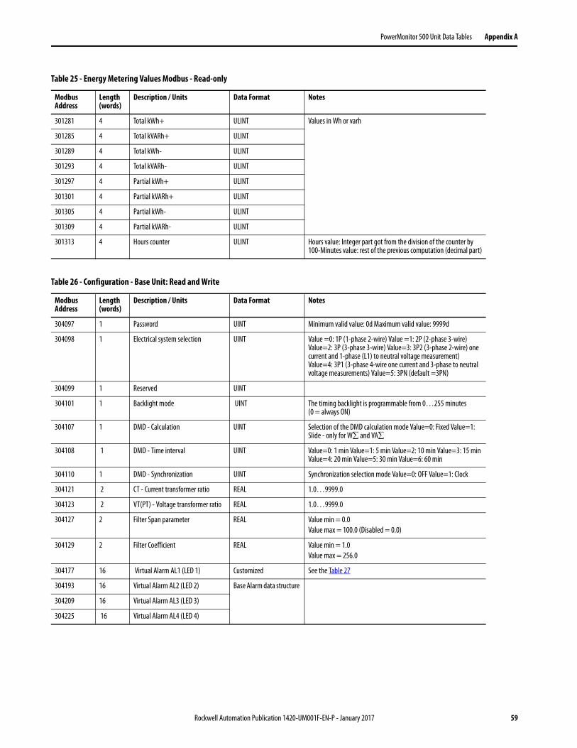
Table 25 - Energy Metering Values Modbus - Read-only
Modbus Address
Length (words)
Description / Units Data Format Notes
301281 4 Total kWh+ ULINT Values in Wh or varh
301285 4 Total kVARh+ ULINT
301289 4 Total kWh- ULINT
301293 4 Total kVARh- ULINT
301297 4 Partial kWh+ ULINT
301301 4 Partial kVARh+ ULINT
301305 4 Partial kWh- ULINT
301309 4 Partial kVARh- ULINT
301313 4 Hours counter ULINT Hours value: Integer part got from the division of the counter by 100-Minutes value: rest of the previous computation (decimal part)
Table 26 - Configuration - Base Unit: Read and Write
Modbus Address
Length (words)
Description / Units Data Format Notes
304097 1 Password UINT Minimum valid value: 0d Maximum valid value: 9999d
304098 1 Electrical system selection UINT Value =0: 1P (1-phase 2-wire) Value =1: 2P (2-phase 3-wire) Value=2: 3P (3-phase 3-wire) Value=3: 3P2 (3-phase 2-wire) one current and 1-phase (L1) to neutral voltage measurement) Value=4: 3P1 (3-phase 4-wire one current and 3-phase to neutral voltage measurements) Value=5: 3PN (default =3PN)
304099 1 Reserved UINT
304101 1 Backlight mode UINT The timing backlight is programmable from 0…255 minutes (0 = always ON)
304107 1 DMD - Calculation UINT Selection of the DMD calculation mode Value=0: Fixed Value=1: Slide - only for W and VA
304108 1 DMD - Time interval UINT Value=0: 1 min Value=1: 5 min Value=2: 10 min Value=3: 15 min Value=4: 20 min Value=5: 30 min Value=6: 60 min
304110 1 DMD - Synchronization UINT Synchronization selection mode Value=0: OFF Value=1: Clock
304121 2 CT - Current transformer ratio REAL 1.0…9999.0
304123 2 VT(PT) - Voltage transformer ratio REAL 1.0…9999.0
304127 2 Filter Span parameter REAL Value min = 0.0
Value max = 100.0 (Disabled = 0.0)
304129 2 Filter Coefficient REAL Value min = 1.0
Value max = 256.0
304177 16 Virtual Alarm AL1 (LED 1) Customized See the Table 27
304193 16 Virtual Alarm AL2 (LED 2) Base Alarm data structure
304209 16 Virtual Alarm AL3 (LED 3)
304225 16 Virtual Alarm AL4 (LED 4)
Rockwell Automation Publication 1420-UM001F-EN-P - January 2017 59
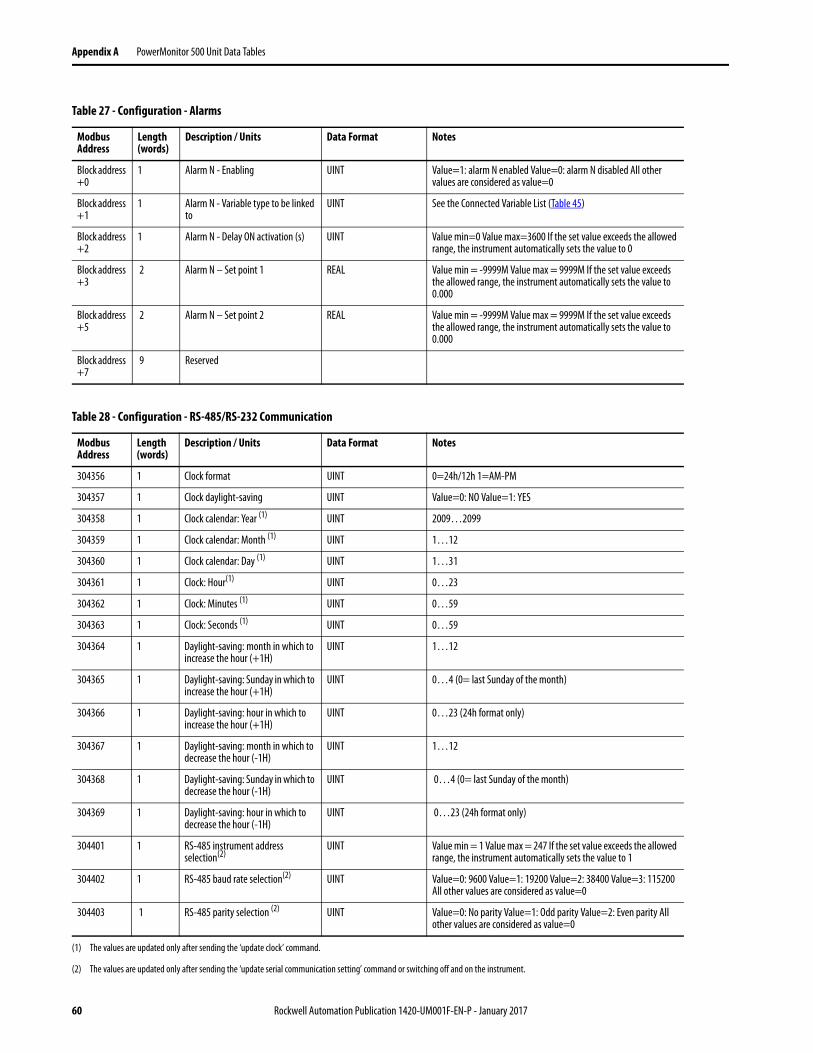
Appendix A PowerMonitor 500 Unit Data Tables
Table 27 - Configuration - Alarms
Modbus Address
Length (words)
Description / Units Data Format Notes
Block address +0
1 Alarm N - Enabling UINT Value=1: alarm N enabled Value=0: alarm N disabled All other values are considered as value=0
Block address +1
1 Alarm N - Variable type to be linked to
UINT See the Connected Variable List (Table 45)
Block address +2
1 Alarm N - Delay ON activation (s) UINT Value min=0 Value max=3600 If the set value exceeds the allowed range, the instrument automatically sets the value to 0
Block address +3
2 Alarm N – Set point 1 REAL Value min = -9999M Value max = 9999M If the set value exceeds the allowed range, the instrument automatically sets the value to 0.000
Block address +5
2 Alarm N – Set point 2 REAL Value min = -9999M Value max = 9999M If the set value exceeds the allowed range, the instrument automatically sets the value to 0.000
Block address +7
9 Reserved
Table 28 - Configuration - RS-485/RS-232 Communication
Modbus Address
Length (words)
Description / Units Data Format Notes
304356 1 Clock format UINT 0=24h/12h 1=AM-PM
304357 1 Clock daylight-saving UINT Value=0: NO Value=1: YES
304358 1 Clock calendar: Year (1) UINT 2009…2099
304359 1 Clock calendar: Month (1) UINT 1…12
304360 1 Clock calendar: Day (1) UINT 1…31
304361 1 Clock: Hour(1) UINT 0…23
304362 1 Clock: Minutes (1) UINT 0…59
304363 1 Clock: Seconds (1) UINT 0…59
304364 1 Daylight-saving: month in which to increase the hour (+1H)
UINT 1…12
304365 1 Daylight-saving: Sunday in which to increase the hour (+1H)
UINT 0…4 (0= last Sunday of the month)
304366 1 Daylight-saving: hour in which to increase the hour (+1H)
UINT 0…23 (24h format only)
304367 1 Daylight-saving: month in which to decrease the hour (-1H)
UINT 1…12
304368 1 Daylight-saving: Sunday in which to decrease the hour (-1H)
UINT 0…4 (0= last Sunday of the month)
304369 1 Daylight-saving: hour in which to decrease the hour (-1H)
UINT 0…23 (24h format only)
304401 1 RS-485 instrument address selection(2)
UINT Value min = 1 Value max = 247 If the set value exceeds the allowed range, the instrument automatically sets the value to 1
304402 1 RS-485 baud rate selection(2) UINT Value=0: 9600 Value=1: 19200 Value=2: 38400 Value=3: 115200 All other values are considered as value=0
304403 1 RS-485 parity selection (2) UINT Value=0: No parity Value=1: Odd parity Value=2: Even parity All other values are considered as value=0
(1) The values are updated only after sending the ‘update clock’ command.
(2) The values are updated only after sending the ‘update serial communication setting’ command or switching off and on the instrument.
60 Rockwell Automation Publication 1420-UM001F-EN-P - January 2017
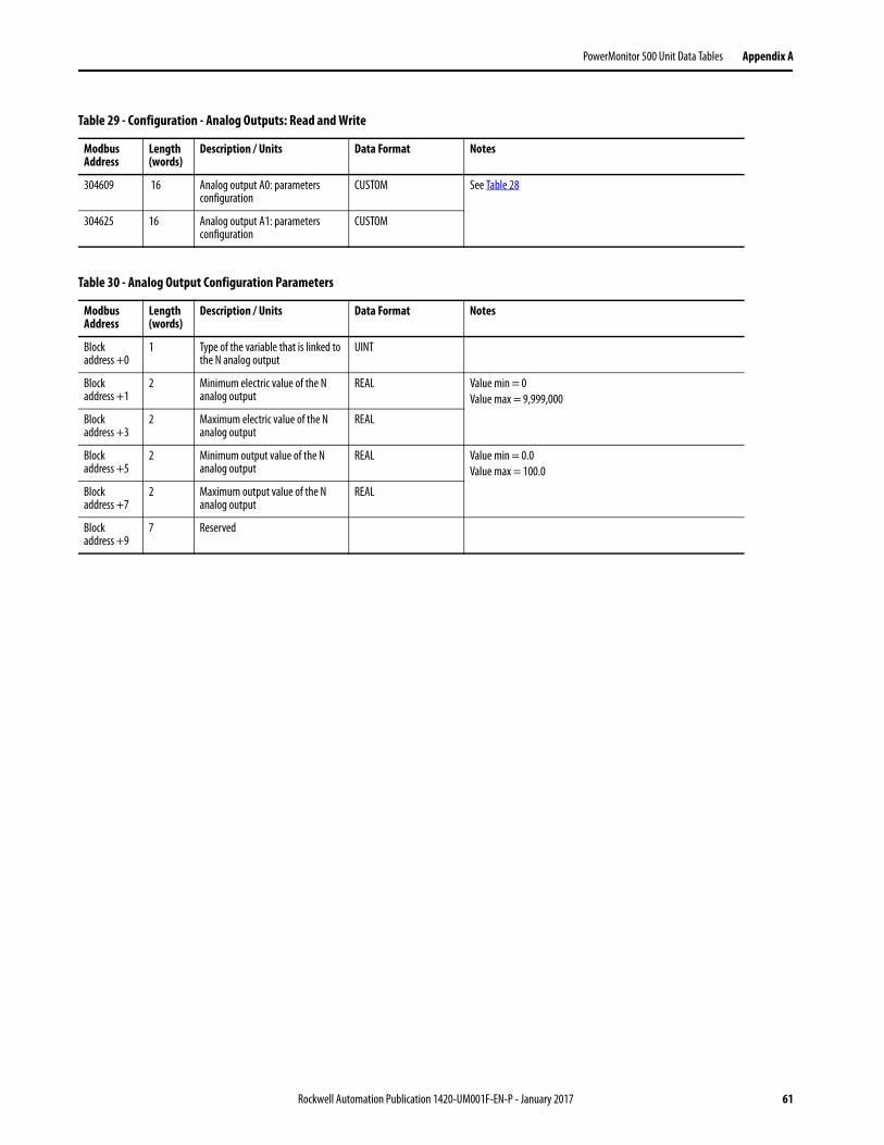
PowerMonitor 500 Unit Data Tables Appendix A
Table 29 - Configuration - Analog Outputs: Read and Write
Modbus Address
Length (words)
Description / Units Data Format Notes
304609 16 Analog output A0: parameters configuration
CUSTOM See Table 28
304625 16 Analog output A1: parameters configuration
CUSTOM
Table 30 - Analog Output Configuration Parameters
Modbus Address
Length (words)
Description / Units Data Format Notes
Block address +0
1 Type of the variable that is linked to the N analog output
UINT
Block address +1
2 Minimum electric value of the N analog output
REAL Value min = 0
Value max = 9,999,000
Block address +3
2 Maximum electric value of the N analog output
REAL
Block address +5
2 Minimum output value of the N analog output
REAL Value min = 0.0
Value max = 100.0
Block address +7
2 Maximum output value of the N analog output
REAL
Block address +9
7 Reserved
Rockwell Automation Publication 1420-UM001F-EN-P - January 2017 61
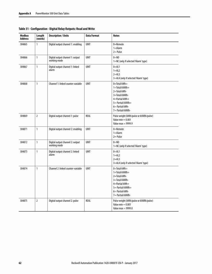
Appendix A PowerMonitor 500 Unit Data Tables
Table 31 - Configuration - Digital Relay Outputs: Read and Write
Modbus Address
Length (words)
Description / Units Data Format Notes
304865 1 Digital output channel 1: enabling UINT 0=Remote
1=Alarm
2= Pulse
304866 1 Digital output channel 1: output working mode
UINT 0=NO
1=NC (only if selected ‘Alarm’ type)
304867 1 Digital output channel 1: linked alarm
UINT 0=AL1
1=AL2
2=AL3
3=AL4 (only if selected ‘Alarm’ type)
304868 1 Channel 1: linked counter-variable UINT 0=Total kWh+
1=Total kVARh+
2=Total kWh-
3=Total kVARh-
4=Partial kWh+
5= Partial kVARh+
6= Partial kWh-
7= Partial kVARh-
304869 2 Digital output channel 1: pulse REAL Pulse weight (kWh/pulse or kVARh/pulse)
Value min = 0.001
Value max = 9999.9
304871 1 Digital output channel 2: enabling UINT 0=Remote
1=Alarm
2= Pulse
304872 1 Digital output channel 2: output working mode
UINT 0=NO
1=NC (only if selected ‘Alarm’ type)
304873 1 Digital output channel 2: linked alarm
UINT 0=AL1
1=AL2
2=AL3
3=AL4 (only if selected ‘Alarm’ type)
304874 1 Channel 2: linked counter-variable UINT 0=Total kWh+
1=Total kVARh+
2=Total kWh-
3=Total kVARh-
4=Partial kWh+
5= Partial kVARh+
6= Partial kWh-
7= Partial kVARh-
304875 2 Digital output channel 2: pulse REAL Pulse weight (kWh/pulse or kVARh/pulse)
Value min = 0.001
Value max = 9999.0
62 Rockwell Automation Publication 1420-UM001F-EN-P - January 2017
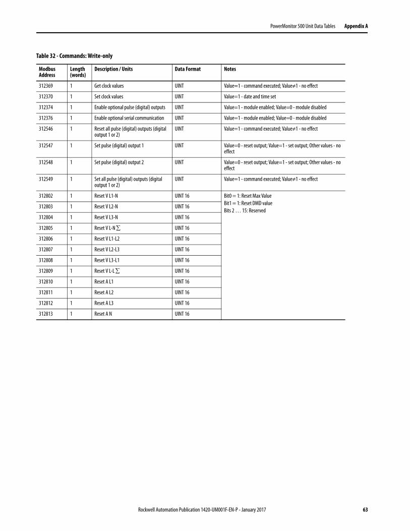
PowerMonitor 500 Unit Data Tables Appendix A
Table 32 - Commands: Write-only
Modbus Address
Length (words)
Description / Units Data Format Notes
312369 1 Get clock values UINT Value=1 - command executed; Value≠1 - no effect
312370 1 Set clock values UINT Value=1 - date and time set
312374 1 Enable optional pulse (digital) outputs UINT Value=1 - module enabled; Value=0 - module disabled
312376 1 Enable optional serial communication UINT Value=1 - module enabled; Value=0 - module disabled
312546 1 Reset all pulse (digital) outputs (digital output 1 or 2)
UINT Value=1 - command executed; Value≠1 - no effect
312547 1 Set pulse (digital) output 1 UINT Value=0 - reset output; Value=1 - set output; Other values - no effect
312548 1 Set pulse (digital) output 2 UINT Value=0 - reset output; Value=1 - set output; Other values - no effect
312549 1 Set all pulse (digital) outputs (digital output 1 or 2)
UINT Value=1 - command executed; Value≠1 - no effect
312802 1 Reset V L1-N UINT 16 Bit0 = 1: Reset Max Value
Bit1 = 1: Reset DMD value
Bits 2 … 15: Reserved312803 1 Reset V L2-N UINT 16
312804 1 Reset V L3-N UINT 16
312805 1 Reset V L-N UINT 16
312806 1 Reset V L1-L2 UINT 16
312807 1 Reset V L2-L3 UINT 16
312808 1 Reset V L3-L1 UINT 16
312809 1 Reset V L-L UINT 16
312810 1 Reset A L1 UINT 16
312811 1 Reset A L2 UINT 16
312812 1 Reset A L3 UINT 16
312813 1 Reset A N UINT 16
Rockwell Automation Publication 1420-UM001F-EN-P - January 2017 63
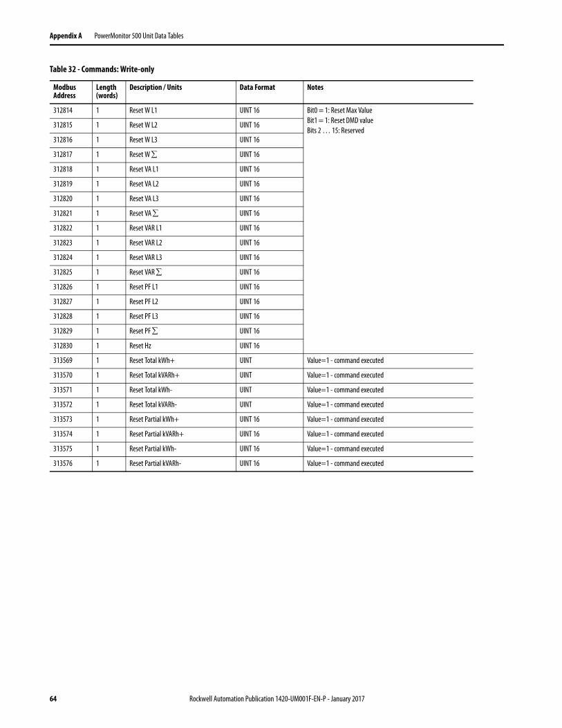
Appendix A PowerMonitor 500 Unit Data Tables
312814 1 Reset W L1 UINT 16 Bit0 = 1: Reset Max Value
Bit1 = 1: Reset DMD value
Bits 2 … 15: Reserved312815 1 Reset W L2 UINT 16
312816 1 Reset W L3 UINT 16
312817 1 Reset W UINT 16
312818 1 Reset VA L1 UINT 16
312819 1 Reset VA L2 UINT 16
312820 1 Reset VA L3 UINT 16
312821 1 Reset VA UINT 16
312822 1 Reset VAR L1 UINT 16
312823 1 Reset VAR L2 UINT 16
312824 1 Reset VAR L3 UINT 16
312825 1 Reset VAR UINT 16
312826 1 Reset PF L1 UINT 16
312827 1 Reset PF L2 UINT 16
312828 1 Reset PF L3 UINT 16
312829 1 Reset PF UINT 16
312830 1 Reset Hz UINT 16
313569 1 Reset Total kWh+ UINT Value=1 - command executed
313570 1 Reset Total kVARh+ UINT Value=1 - command executed
313571 1 Reset Total kWh- UINT Value=1 - command executed
313572 1 Reset Total kVARh- UINT Value=1 - command executed
313573 1 Reset Partial kWh+ UINT 16 Value=1 - command executed
313574 1 Reset Partial kVARh+ UINT 16 Value=1 - command executed
313575 1 Reset Partial kWh- UINT 16 Value=1 - command executed
313576 1 Reset Partial kVARh- UINT 16 Value=1 - command executed
Table 32 - Commands: Write-only
Modbus Address
Length (words)
Description / Units Data Format Notes
64 Rockwell Automation Publication 1420-UM001F-EN-P - January 2017
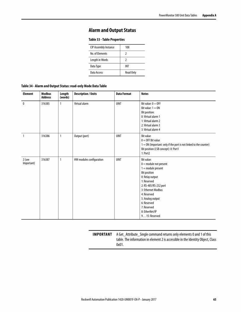
PowerMonitor 500 Unit Data Tables Appendix A
Alarm and Output Status
Table 33 - Table Properties
CIP Assembly Instance 108
No. of Elements 2
Length in Words 2
Data Type INT
Data Access Read Only
Table 34 - Alarm and Output Status: read-only Mode Data Table
Element Modbus Address
Length (words)
Description / Units Data Format Notes
0 316385 1 Virtual alarm UINT Bit value: 0 = OFF
Bit value: 1 = ON
Bit position:
0: Virtual alarm 1
1: Virtual alarm 2
2: Virtual alarm 3
3: Virtual alarm 4
1 316386 1 Output (port) UINT Bit value
0 = OFF Bit value
1 = ON (Important: only if the port is not linked to the counter)
Bit position (LSB concept): 0: Port1
1: Port2
2 (see Important)
316387 1 HW modules configuration UINT Bit value:
0 = module not present
1 = module present
Bit position
0: Relay output
1: Reserved
2: RS-485/RS-232 port
3: Ethernet Modbus
4: Reserved
5: Analog output
6: Reserved
7: Reserved
8: EtherNet/IP
9…15: Reserved
IMPORTANT A Get_Attribute_Single command returns only elements 0 and 1 of this
table. The information in element 2 is accessible in the Identity Object, Class
0x01.
Rockwell Automation Publication 1420-UM001F-EN-P - January 2017 65

Appendix A PowerMonitor 500 Unit Data Tables
Notes:
66 Rockwell Automation Publication 1420-UM001F-EN-P - January 2017
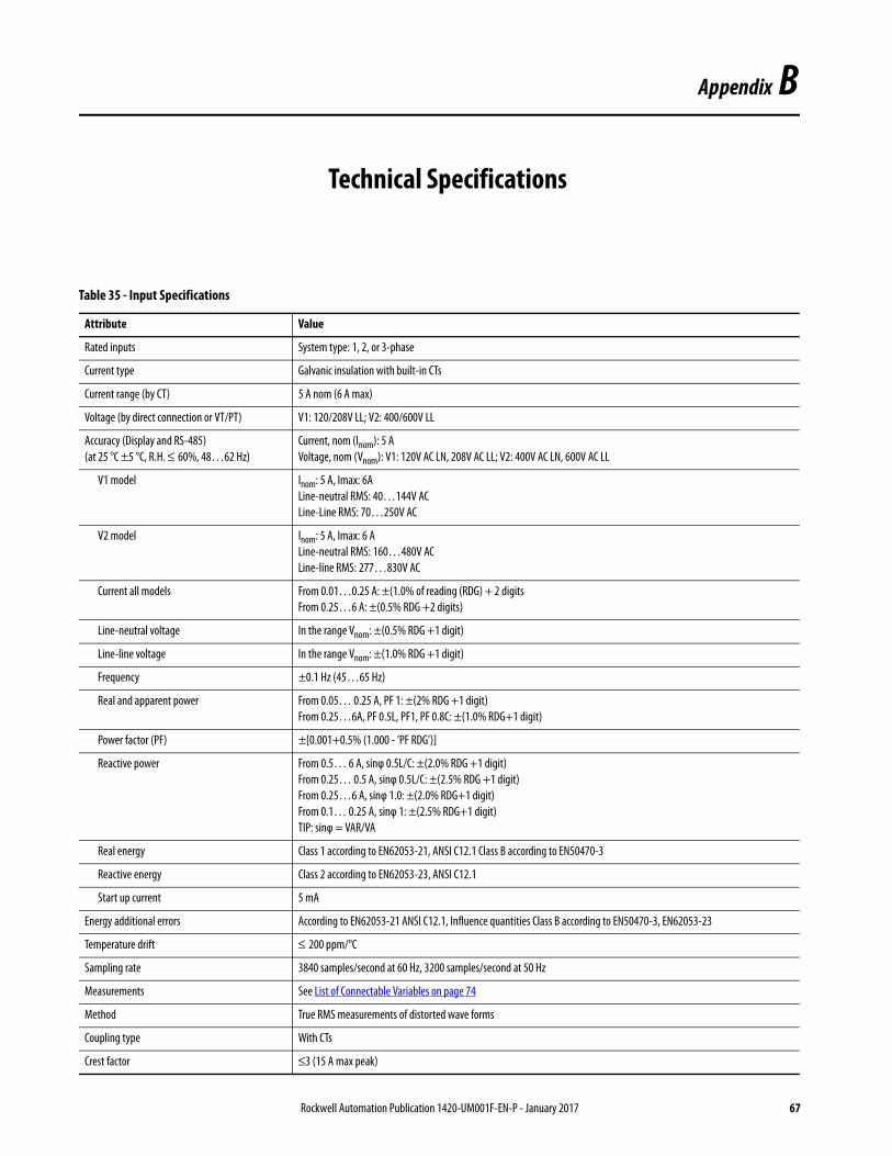
Appendix B
Technical Specifications
Table 35 - Input Specifications
Attribute Value
Rated inputs System type: 1, 2, or 3-phase
Current type Galvanic insulation with built-in CTs
Current range (by CT) 5 A nom (6 A max)
Voltage (by direct connection or VT/PT) V1: 120/208V LL; V2: 400/600V LL
Accuracy (Display and RS-485)
(at 25 °C ±5 °C, R.H. ≤ 60%, 48…62 Hz)
Current, nom (Inom): 5 A
Voltage, nom (Vnom): V1: 120V AC LN, 208V AC LL; V2: 400V AC LN, 600V AC LL
V1 model Inom: 5 A, Imax: 6A
Line-neutral RMS: 40…144V AC
Line-Line RMS: 70…250V AC
V2 model Inom: 5 A, Imax: 6 A
Line-neutral RMS: 160…480V AC
Line-line RMS: 277…830V AC
Current all models From 0.01…0.25 A: ±(1.0% of reading (RDG) + 2 digits
From 0.25…6 A: ±(0.5% RDG +2 digits)
Line-neutral voltage In the range Vnom: ±(0.5% RDG +1 digit)
Line-line voltage In the range Vnom: ±(1.0% RDG +1 digit)
Frequency ±0.1 Hz (45…65 Hz)
Real and apparent power From 0.05… 0.25 A, PF 1: ±(2% RDG +1 digit)
From 0.25…6A, PF 0.5L, PF1, PF 0.8C: ±(1.0% RDG+1 digit)
Power factor (PF) ±[0.001+0.5% (1.000 - ‘PF RDG’)]
Reactive power From 0.5… 6 A, sinφ 0.5L/C: ±(2.0% RDG +1 digit)
From 0.25… 0.5 A, sinφ 0.5L/C: ±(2.5% RDG +1 digit)
From 0.25…6 A, sinφ 1.0: ±(2.0% RDG+1 digit)
From 0.1… 0.25 A, sinφ 1: ±(2.5% RDG+1 digit)
TIP: sinφ = VAR/VA
Real energy Class 1 according to EN62053-21, ANSI C12.1 Class B according to EN50470-3
Reactive energy Class 2 according to EN62053-23, ANSI C12.1
Start up current 5 mA
Energy additional errors According to EN62053-21 ANSI C12.1, Influence quantities Class B according to EN50470-3, EN62053-23
Temperature drift ≤ 200 ppm/°C
Sampling rate 3840 samples/second at 60 Hz, 3200 samples/second at 50 Hz
Measurements See List of Connectable Variables on page 74
Method True RMS measurements of distorted wave forms
Coupling type With CTs
Crest factor ≤3 (15 A max peak)
Rockwell Automation Publication 1420-UM001F-EN-P - January 2017 67
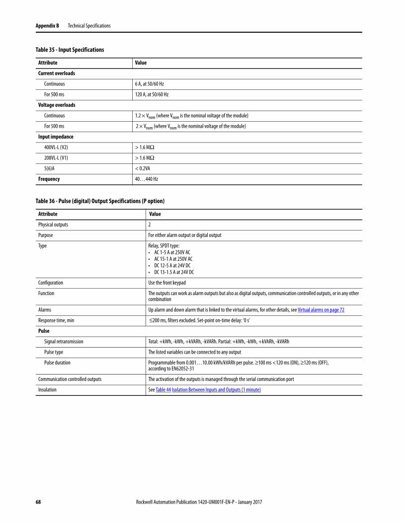
Appendix B Technical Specifications
Current overloads
Continuous 6 A, at 50/60 Hz
For 500 ms 120 A, at 50/60 Hz
Voltage overloads
Continuous 1.2 × Vnom (where Vnom is the nominal voltage of the module)
For 500 ms 2 × Vnom (where Vnom is the nominal voltage of the module)
Input impedance
400VL-L (V2) > 1.6 MΩ
208VL-L (V1) > 1.6 MΩ
5(6)A < 0.2VA
Frequency 40…440 Hz
Table 35 - Input Specifications
Attribute Value
Table 36 - Pulse (digital) Output Specifications (P option)
Attribute Value
Physical outputs 2
Purpose For either alarm output or digital output
Type Relay, SPDT type:• AC 1-5 A at 250V AC• AC 15-1 A at 250V AC• DC 12-5 A at 24V DC• DC 13-1.5 A at 24V DC
Configuration Use the front keypad
Function The outputs can work as alarm outputs but also as digital outputs, communication controlled outputs, or in any other combination
Alarms Up alarm and down alarm that is linked to the virtual alarms, for other details, see Virtual alarms on page 72
Response time, min ≤200 ms, filters excluded. Set-point on-time delay: ‘0 s’
Pulse
Signal retransmission Total: +kWh, -kWh, +kVARh, -kVARh. Partial: +kWh, -kWh, +kVARh, -kVARh
Pulse type The listed variables can be connected to any output
Pulse duration Programmable from 0.001…10.00 kWh/kVARh per pulse. ≥100 ms <120 ms (ON), ≥120 ms (OFF), according to EN62052-31
Communication controlled outputs The activation of the outputs is managed through the serial communication port
Insulation See Table 44 Isolation Between Inputs and Outputs (1 minute)
68 Rockwell Automation Publication 1420-UM001F-EN-P - January 2017
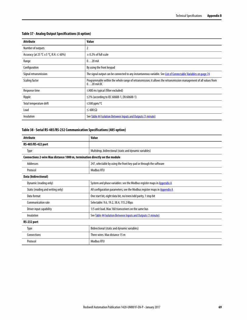
Technical Specifications Appendix B
Table 37 - Analog Output Specifications (A option)
Attribute Value
Number of outputs 2
Accuracy (at 25 °C ±5 °C, R.H. ≤ 60%) ± 0.2% of full scale
Range 0…20 mA
Configuration By using the front keypad
Signal retransmission The signal output can be connected to any instantaneous variable. See List of Connectable Variables on page 74
Scaling factor Programmable within the whole range of retransmission; it allows the retransmission management of all values from 0…20 mA DC
Response time ≤400 ms typical (filter excluded)
Ripple ≤1% (according to IEC 60688-1, EN 60688-1)
Total temperature drift ≤500 ppm/°C
Load ≤ 600 Ω
Insulation See Table 44 Isolation Between Inputs and Outputs (1 minute)
Table 38 - Serial RS-485/RS-232 Communication Specifications (485 option)
Attribute Value
RS-485/RS-422 port
Type Multidrop, bidirectional (static and dynamic variables)
Connections 2-wire Max distance 1000 m, termination directly on the module
Addresses 247, selectable by using the front key-pad or through the software
Protocol Modbus RTU
Data (bidirectional)
Dynamic (reading only) System and phase variables: see the Modbus register maps in Appendix A
Static (reading and writing only) All configuration parameters; see the Modbus register maps in Appendix A
Data format One start bit, eight data bit, no/even/odd parity, 1 stop bit
Communication rate Selectable: 9.6, 19.2, 38.4, 115.2 Kbps
Driver input capability 1/5 unit load. Max 160 transceivers on the same bus
Insulation See Table 44 Isolation Between Inputs and Outputs (1 minute)
RS-232 port
Type Bidirectional (static and dynamic variables)
Connections Three wires. Max distance 15 m
Protocol Modbus RTU
Rockwell Automation Publication 1420-UM001F-EN-P - January 2017 69
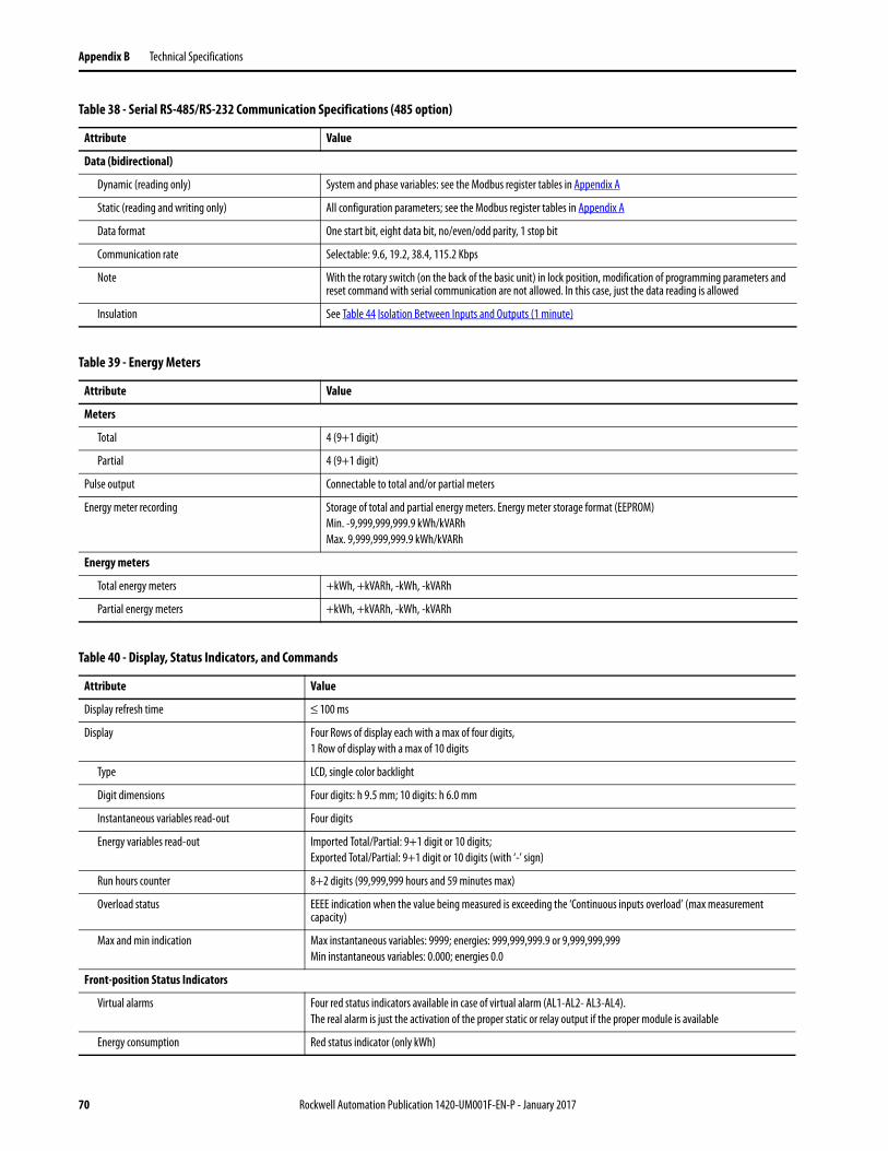
Appendix B Technical Specifications
Data (bidirectional)
Dynamic (reading only) System and phase variables: see the Modbus register tables in Appendix A
Static (reading and writing only) All configuration parameters; see the Modbus register tables in Appendix A
Data format One start bit, eight data bit, no/even/odd parity, 1 stop bit
Communication rate Selectable: 9.6, 19.2, 38.4, 115.2 Kbps
Note With the rotary switch (on the back of the basic unit) in lock position, modification of programming parameters and reset command with serial communication are not allowed. In this case, just the data reading is allowed
Insulation See Table 44 Isolation Between Inputs and Outputs (1 minute)
Table 38 - Serial RS-485/RS-232 Communication Specifications (485 option)
Attribute Value
Table 39 - Energy Meters
Attribute Value
Meters
Total 4 (9+1 digit)
Partial 4 (9+1 digit)
Pulse output Connectable to total and/or partial meters
Energy meter recording Storage of total and partial energy meters. Energy meter storage format (EEPROM)
Min. -9,999,999,999.9 kWh/kVARh
Max. 9,999,999,999.9 kWh/kVARh
Energy meters
Total energy meters +kWh, +kVARh, -kWh, -kVARh
Partial energy meters +kWh, +kVARh, -kWh, -kVARh
Table 40 - Display, Status Indicators, and Commands
Attribute Value
Display refresh time ≤ 100 ms
Display Four Rows of display each with a max of four digits,
1 Row of display with a max of 10 digits
Type LCD, single color backlight
Digit dimensions Four digits: h 9.5 mm; 10 digits: h 6.0 mm
Instantaneous variables read-out Four digits
Energy variables read-out Imported Total/Partial: 9+1 digit or 10 digits;
Exported Total/Partial: 9+1 digit or 10 digits (with ‘-’ sign)
Run hours counter 8+2 digits (99,999,999 hours and 59 minutes max)
Overload status EEEE indication when the value being measured is exceeding the ‘Continuous inputs overload’ (max measurement capacity)
Max and min indication Max instantaneous variables: 9999; energies: 999,999,999.9 or 9,999,999,999
Min instantaneous variables: 0.000; energies 0.0
Front-position Status Indicators
Virtual alarms Four red status indicators available in case of virtual alarm (AL1-AL2- AL3-AL4).
The real alarm is just the activation of the proper static or relay output if the proper module is available
Energy consumption Red status indicator (only kWh)
70 Rockwell Automation Publication 1420-UM001F-EN-P - January 2017
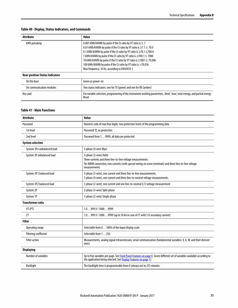
Technical Specifications Appendix B
kWh pulsating 0.001 kWh/kVARh by pulse if the Ct ratio by VT ratio is ≤ 70.01 kWh/kVARh by pulse if the Ct ratio by VT ratio is ≥7.1 ≤ 70.0
0.1 kWh/kVARh by pulse if the Ct ratio by VT ratio is ≥70.1 ≤700.0
1 kWh/kVARh by pulse if the Ct ratio by VT ratio is ≥700.1 ≤ 7000
10 kWh/kVARh by pulse if the Ct ratio by VT ratio is ≥7001 ≤ 70.00k
100 kWh/kVARh by pulse if the Ct ratio by VT ratio is >70.01k
Max frequency: 16 Hz, according to EN50470-1
Rear-position Status Indicators
On the base Green as power-on
On communication modules Two status indicators: one for TX (green) and one for RX (amber)
Key-pad For variable selection, programming of the instrument working parameters, ‘dmd’, ‘max’, total energy, and partial energy Reset
Table 40 - Display, Status Indicators, and Commands
Attribute Value
Table 41 - Main Functions
Attribute Value
Password Numeric code of max four digits; two protection levels of the programming data
1st level Password ‘0’, no protection
2nd level Password from 1…9999, all data are protected
System selection
System 3P.n unbalanced load 3-phase (4-wire Wye)
System 3P unbalanced load 3-phase (3-wire) Delta
Three currents and three line-to-line voltage measurements
For ARON connection, two currents (with special wiring on screw terminals) and three line-to-line voltage measurements.
System 3P.1 balanced load 3-phase (3-wire), one current and three line-to-line measurements.
3-phase (4-wire), one current and three line-to-neutral voltage measurements.
System 3P.2 balanced load 3-phase (2-wire), one current and one line-to-neutral (L1) voltage measurement
System 2P 2-phase (3-wire) Split-phase
System 1P 1-phase (2-wire) Single phase
Transformer ratio
VT (PT) 1.0…999.9 / 1000…9999
CT 1.0…999.9 / 1000…9999 (up to 50 kA in case of CT with 5 A secondary current)
Filter
Operating range Selectable from 0…100% of the input display scale
Filtering coefficient Selectable from 1…256
Filter action Measurements, analog signal retransmission, serial communication (fundamental variables: V, A, W, and their derived ones)
Displaying
Number of variables Up to five variables per page. See Front Panel Features on page 9. Seven different set of variables available according to the application being selected. See Display Features on page 11
Backlight The backlight time is programmable from 0 (always on) to 255 minutes
Rockwell Automation Publication 1420-UM001F-EN-P - January 2017 71
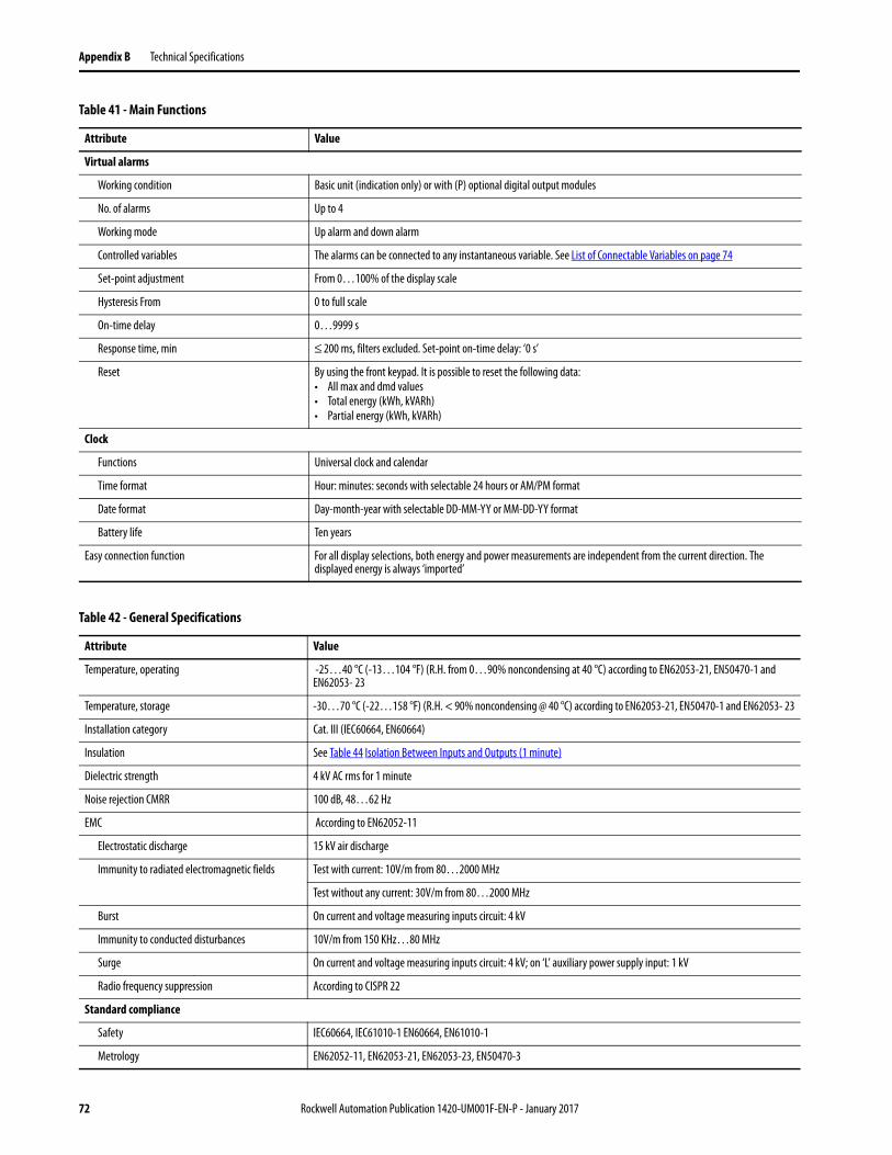
Appendix B Technical Specifications
Virtual alarms
Working condition Basic unit (indication only) or with (P) optional digital output modules
No. of alarms Up to 4
Working mode Up alarm and down alarm
Controlled variables The alarms can be connected to any instantaneous variable. See List of Connectable Variables on page 74
Set-point adjustment From 0…100% of the display scale
Hysteresis From 0 to full scale
On-time delay 0…9999 s
Response time, min ≤ 200 ms, filters excluded. Set-point on-time delay: ‘0 s’
Reset By using the front keypad. It is possible to reset the following data:• All max and dmd values• Total energy (kWh, kVARh)• Partial energy (kWh, kVARh)
Clock
Functions Universal clock and calendar
Time format Hour: minutes: seconds with selectable 24 hours or AM/PM format
Date format Day-month-year with selectable DD-MM-YY or MM-DD-YY format
Battery life Ten years
Easy connection function For all display selections, both energy and power measurements are independent from the current direction. The displayed energy is always ‘imported’
Table 41 - Main Functions
Attribute Value
Table 42 - General Specifications
Attribute Value
Temperature, operating -25…40 °C (-13…104 °F) (R.H. from 0…90% noncondensing at 40 °C) according to EN62053-21, EN50470-1 and EN62053- 23
Temperature, storage -30…70 °C (-22…158 °F) (R.H. < 90% noncondensing @ 40 °C) according to EN62053-21, EN50470-1 and EN62053- 23
Installation category Cat. III (IEC60664, EN60664)
Insulation See Table 44 Isolation Between Inputs and Outputs (1 minute)
Dielectric strength 4 kV AC rms for 1 minute
Noise rejection CMRR 100 dB, 48…62 Hz
EMC According to EN62052-11
Electrostatic discharge 15 kV air discharge
Immunity to radiated electromagnetic fields Test with current: 10V/m from 80…2000 MHz
Test without any current: 30V/m from 80…2000 MHz
Burst On current and voltage measuring inputs circuit: 4 kV
Immunity to conducted disturbances 10V/m from 150 KHz…80 MHz
Surge On current and voltage measuring inputs circuit: 4 kV; on ‘L’ auxiliary power supply input: 1 kV
Radio frequency suppression According to CISPR 22
Standard compliance
Safety IEC60664, IEC61010-1 EN60664, EN61010-1
Metrology EN62052-11, EN62053-21, EN62053-23, EN50470-3
72 Rockwell Automation Publication 1420-UM001F-EN-P - January 2017
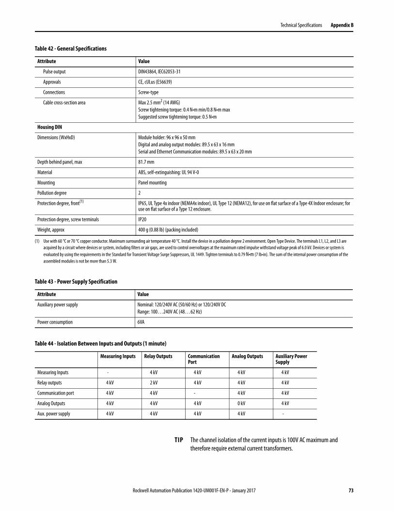
Technical Specifications Appendix B
Pulse output DIN43864, IEC62053-31
Approvals CE, cULus (E56639)
Connections Screw-type
Cable cross-section area Max 2.5 mm2 (14 AWG)
Screw tightening torque: 0.4 N•m min/0.8 N•m max
Suggested screw tightening torque: 0.5 N•m
Housing DIN
Dimensions (WxHxD) Module holder: 96 x 96 x 50 mm
Digital and analog output modules: 89.5 x 63 x 16 mm
Serial and Ethernet Communication modules: 89.5 x 63 x 20 mm
Depth behind panel, max 81.7 mm
Material ABS, self-extinguishing: UL 94 V-0
Mounting Panel mounting
Pollution degree 2
Protection degree, front(1) IP65, UL Type 4x indoor (NEMA4x indoor), UL Type 12 (NEMA12), for use on flat surface of a Type 4X Indoor enclosure; for use on flat surface of a Type 12 enclosure.
Protection degree, screw terminals IP20
Weight, approx 400 g (0.88 lb) (packing included)
(1) Use with 60 °C or 70 °C copper conductor. Maximum surrounding air temperature 40 °C. Install the device in a pollution degree 2 environment. Open Type Device. The terminals L1, L2, and L3 are
acquired by a circuit where devices or system, including filters or air gaps, are used to control overvoltages at the maximum rated impulse withstand voltage peak of 6.0 kV. Devices or system is
evaluated by using the requirements in the Standard for Transient Voltage Surge Suppressors, UL 1449. Tighten terminals to 0.79 N•m (7 lb•in). The sum of the internal power consumption of the
assembled modules is not be more than 5.3 W.
Table 42 - General Specifications
Attribute Value
Table 43 - Power Supply Specification
Attribute Value
Auxiliary power supply Nominal: 120/240V AC (50/60 Hz) or 120/240V DC
Range: 100…240V AC (48…62 Hz)
Power consumption 6VA
Table 44 - Isolation Between Inputs and Outputs (1 minute)
Measuring Inputs Relay Outputs Communication Port
Analog Outputs Auxiliary Power Supply
Measuring Inputs - 4 kV 4 kV 4 kV 4 kV
Relay outputs 4 kV 2 kV 4 kV 4 kV 4 kV
Communication port 4 kV 4 kV - 4 kV 4 kV
Analog Outputs 4 kV 4 kV 4 kV 0 kV 4 kV
Aux. power supply 4 kV 4 kV 4 kV 4 kV -
TIP The channel isolation of the current inputs is 100V AC maximum and
therefore require external current transformers.
Rockwell Automation Publication 1420-UM001F-EN-P - January 2017 73
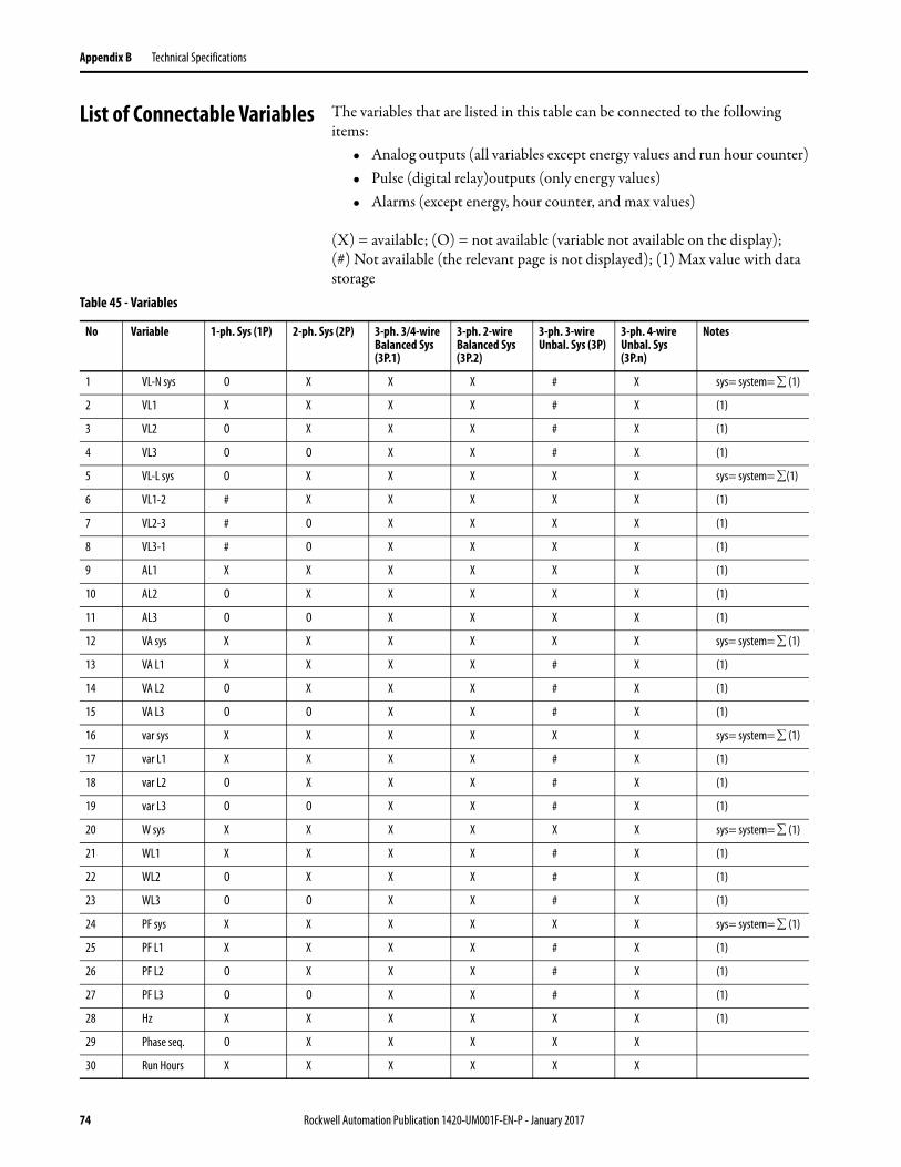
Appendix B Technical Specifications
List of Connectable Variables The variables that are listed in this table can be connected to the following items:
• Analog outputs (all variables except energy values and run hour counter)• Pulse (digital relay)outputs (only energy values)• Alarms (except energy, hour counter, and max values)
(X) = available; (O) = not available (variable not available on the display); (#) Not available (the relevant page is not displayed); (1) Max value with data storage
Table 45 - Variables
No Variable 1-ph. Sys (1P) 2-ph. Sys (2P) 3-ph. 3/4-wire Balanced Sys (3P.1)
3-ph. 2-wire Balanced Sys (3P.2)
3-ph. 3-wire Unbal. Sys (3P)
3-ph. 4-wire Unbal. Sys (3P.n)
Notes
1 VL-N sys O X X X # X sys= system= (1)
2 VL1 X X X X # X (1)
3 VL2 O X X X # X (1)
4 VL3 O O X X # X (1)
5 VL-L sys O X X X X X sys= system= (1)
6 VL1-2 # X X X X X (1)
7 VL2-3 # O X X X X (1)
8 VL3-1 # O X X X X (1)
9 AL1 X X X X X X (1)
10 AL2 O X X X X X (1)
11 AL3 O O X X X X (1)
12 VA sys X X X X X X sys= system= (1)
13 VA L1 X X X X # X (1)
14 VA L2 O X X X # X (1)
15 VA L3 O O X X # X (1)
16 var sys X X X X X X sys= system= (1)
17 var L1 X X X X # X (1)
18 var L2 O X X X # X (1)
19 var L3 O O X X # X (1)
20 W sys X X X X X X sys= system= (1)
21 WL1 X X X X # X (1)
22 WL2 O X X X # X (1)
23 WL3 O O X X # X (1)
24 PF sys X X X X X X sys= system= (1)
25 PF L1 X X X X # X (1)
26 PF L2 O X X X # X (1)
27 PF L3 O O X X # X (1)
28 Hz X X X X X X (1)
29 Phase seq. O X X X X X
30 Run Hours X X X X X X
74 Rockwell Automation Publication 1420-UM001F-EN-P - January 2017
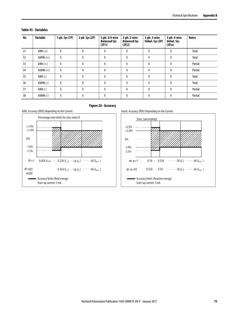
Technical Specifications Appendix B
Figure 26 - Accuracy
31 kWh (+) X X X X X X Total
32 kVARh (+) X X X X # X Total
33 kWh (+) X X X X X X Partial
34 kVARh (+) X X X X # X Partial
35 kWh (-) X X X X X X Total
36 kVARh (-) X X X X # X Total
37 kWh (-) X X X X X X Partial
38 kVARh (-) X X X X # X Partial
Table 45 - Variables
No Variable 1-ph. Sys (1P) 2-ph. Sys (2P) 3-ph. 3/4-wire Balanced Sys (3P.1)
3-ph. 2-wire Balanced Sys (3P.2)
3-ph. 3-wire Unbal. Sys (3P)
3-ph. 4-wire Unbal. Sys (3P.n)
Notes
kWh, Accuracy (RDG) Depending on the Current
Percentage error limits for class index B
6A (Imax )
6A (Imax )
5A (I n )
5A (I n )
0.25A (I tr )
0.25A (I tr )
0.05A (Imin)
Accuracy limits (Real energy)
Start-up current: 5 mA
kvarh, Accuracy (RDG) Depending on the Current
Error (uncertainty)
Accuracy limits (Reactive energy)
Start-up current: 5 mA
PF=1
PF=L0.5
or C0.8
6A (Imax )
6A (Imax )
5A (In )
5A (In )
0.25A
0.5A
0.1A
0.25A
sin φ=1
sin φ=0.5
+1.0%
0%
+1.5%
-1.0%
-1.5%
+2.0%
0%
+2.5%
-2.0%
-2.5%
Rockwell Automation Publication 1420-UM001F-EN-P - January 2017 75
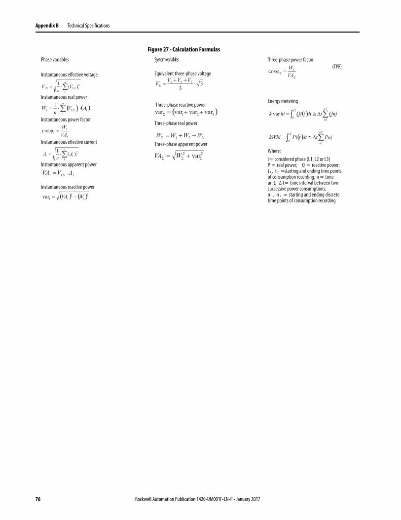
Appendix B Technical Specifications
Figure 27 - Calculation Formulas
System variables
Equivalent three-phase voltage
Three-phase real power
Three-phase reactive power
Three-phase apparent power
Phase variables
Instantaneous effective voltage
Instantaneous real power
Instantaneous power factor
Instantaneous effective current
Instantaneous apparent power
Instantaneous reactive power
Energy metering
Where:
i= considered phase (L1, L2 or L3)P = real power; Q = reactive power;t 1 , t 2 =starting and ending time pointsof consumption recording; n = timeunit; Δ t = time interval between twosuccessive power consumptions; n 1 , n 2 = starting and ending discretetime points of consumption recording
Three-phase power factor
(TPF)
76 Rockwell Automation Publication 1420-UM001F-EN-P - January 2017
Appendix C
PowerMonitor 500 EtherNet/IP Device Profile
This section describes the specific CIP Objects, Instances, Attributes, and Services that are supported by the PowerMonitor™ 500 system. This information is for anyone wishing to integrate the PowerMonitor 500 system into existing or planned shop floor networks.
General For this device profile, we use a PowerMonitor 500 unit and an EtherNet/IP communication module to provide power and energy metering data via an EtherNet/IP network. The data is accessed as instances of the device Assembly Object.
This profile documents objects that are proprietary, or in some way that is altered from their generic behavior. Standard CIP objects that are generic in their interface are documented in the EtherNet/IP specification.
Object Model and Interface The PowerMonitor 500 system is represented by the following Object Model.
Identity Object - CLASS CODE 0x0001
The Identity Object is used to provide identification information about the device. Each node supports at least one instance of the identity object. The Identity Object is used by applications to determine which nodes are on the network. The Identity Object supports Class Attributes (Instance 0) and Instance 1.
See Section 5-2 of the CIP Common Specification for full details of this object.
Object Class Class Code Instance Numbers Number of Connections
Identity 0x0001 1 0
Assembly 0x0004 100d…108d 18
Rockwell Automation Publication 1420-UM001F-EN-P - January 2017 77
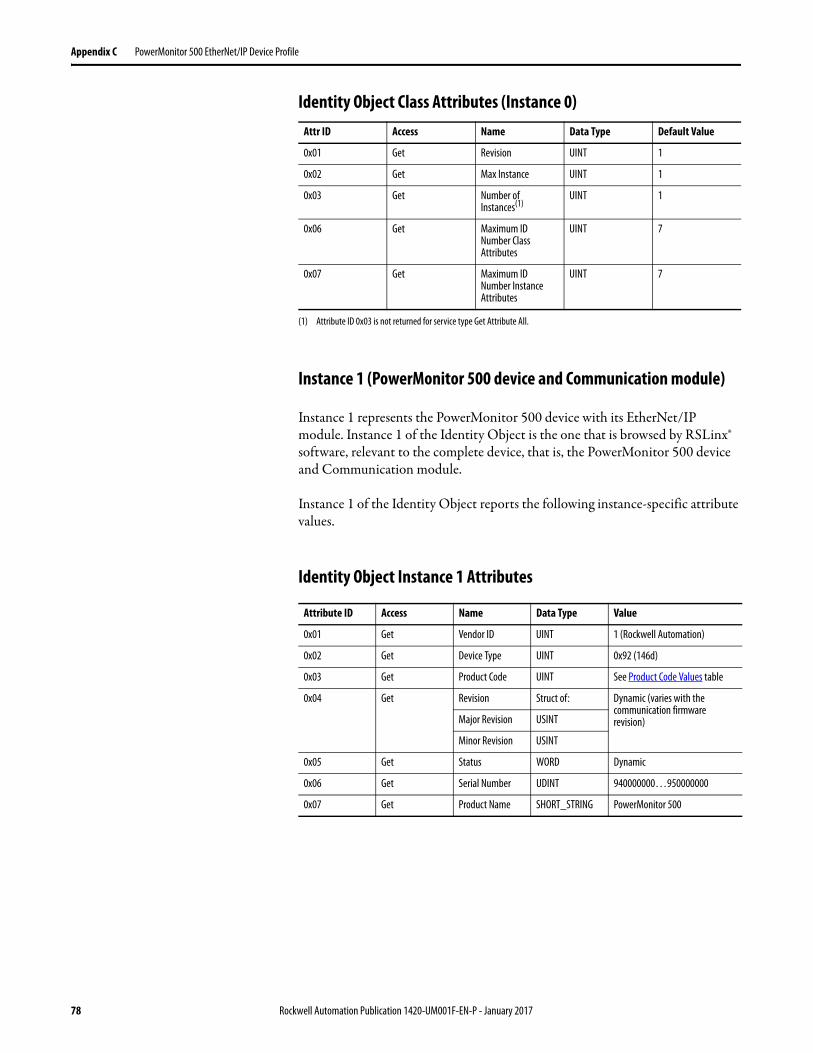
Appendix C PowerMonitor 500 EtherNet/IP Device Profile
Identity Object Class Attributes (Instance 0)
Instance 1 (PowerMonitor 500 device and Communication module)
Instance 1 represents the PowerMonitor 500 device with its EtherNet/IP module. Instance 1 of the Identity Object is the one that is browsed by RSLinx® software, relevant to the complete device, that is, the PowerMonitor 500 device and Communication module.
Instance 1 of the Identity Object reports the following instance-specific attribute values.
Identity Object Instance 1 Attributes
Attr ID Access Name Data Type Default Value
0x01 Get Revision UINT 1
0x02 Get Max Instance UINT 1
0x03 Get Number of Instances(1)
(1) Attribute ID 0x03 is not returned for service type Get Attribute All.
UINT 1
0x06 Get Maximum ID Number Class Attributes
UINT 7
0x07 Get Maximum ID Number Instance Attributes
UINT 7
Attribute ID Access Name Data Type Value
0x01 Get Vendor ID UINT 1 (Rockwell Automation)
0x02 Get Device Type UINT 0x92 (146d)
0x03 Get Product Code UINT See Product Code Values table
0x04 Get Revision Struct of: Dynamic (varies with the communication firmware revision)Major Revision USINT
Minor Revision USINT
0x05 Get Status WORD Dynamic
0x06 Get Serial Number UDINT 940000000…950000000
0x07 Get Product Name SHORT_STRING PowerMonitor 500
78 Rockwell Automation Publication 1420-UM001F-EN-P - January 2017
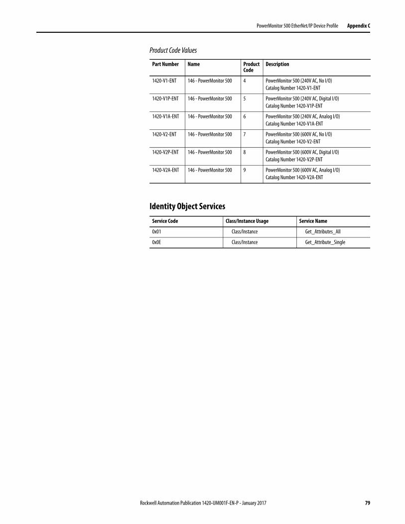
PowerMonitor 500 EtherNet/IP Device Profile Appendix C
Product Code Values
Identity Object Services
Part Number Name Product Code
Description
1420-V1-ENT 146 - PowerMonitor 500 4 PowerMonitor 500 (240V AC, No I/O)
Catalog Number 1420-V1-ENT
1420-V1P-ENT 146 - PowerMonitor 500 5 PowerMonitor 500 (240V AC, Digital I/O)
Catalog Number 1420-V1P-ENT
1420-V1A-ENT 146 - PowerMonitor 500 6 PowerMonitor 500 (240V AC, Analog I/O)
Catalog Number 1420-V1A-ENT
1420-V2-ENT 146 - PowerMonitor 500 7 PowerMonitor 500 (600V AC, No I/O)
Catalog Number 1420-V2-ENT
1420-V2P-ENT 146 - PowerMonitor 500 8 PowerMonitor 500 (600V AC, Digital I/O)
Catalog Number 1420-V2P-ENT
1420-V2A-ENT 146 - PowerMonitor 500 9 PowerMonitor 500 (600V AC, Analog I/O)
Catalog Number 1420-V2A-ENT
Service Code Class/Instance Usage Service Name
0x01 Class/Instance Get_Attributes_All
0x0E Class/Instance Get_Attribute_Single
Rockwell Automation Publication 1420-UM001F-EN-P - January 2017 79
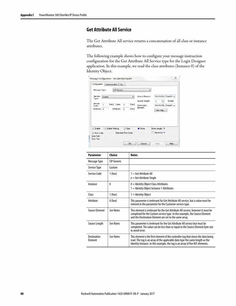
Appendix C PowerMonitor 500 EtherNet/IP Device Profile
Get Attribute All Service
The Get Attribute All service returns a concatenation of all class or instance attributes.
The following example shows how to configure your message instruction configuration for the Get Attribute All Service type for the Logix Designer application. In this example, we read the class attributes (Instance 0) of the Identity Object.
Parameter Choice Notes
Message Type CIP Generic
Service Type Custom
Service Code 1 (hex) 1 = Get Attribute All
e = Get Attribute Single
Instance 0 0 = Identity Object Class Attributes
1 = Identity Object Instance 1 Attributes
Class 1 (hex) 1 = Identity Object
Attribute 0 (hex) This parameter is irrelevant for Get Attribute All service, but a value must be entered in this parameter for the Customer service type.
Source Element See Notes This element is irrelevant for the Get Attribute All service, however it must be completed for the Custom service type. In this example, the Source Element and the Destination Element are set to the same array.
Source Length See Notes This parameter is irrelevant for the Get Attribute All service but must be completed. The value can be less than or equal to the Source Element byte size to avoid error.
Destination Element
See Notes This element is the first element of the controller tag that stores the data being read. The tag is an array of the applicable data type the same length as the Identity Instance. In this example, the tag is an array of five INT elements.
80 Rockwell Automation Publication 1420-UM001F-EN-P - January 2017
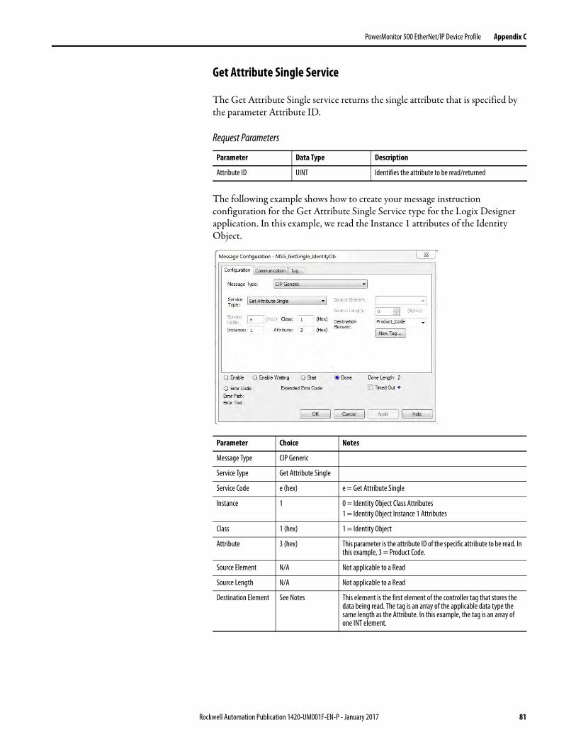
PowerMonitor 500 EtherNet/IP Device Profile Appendix C
Get Attribute Single Service
The Get Attribute Single service returns the single attribute that is specified by the parameter Attribute ID.
Request Parameters
The following example shows how to create your message instruction configuration for the Get Attribute Single Service type for the Logix Designer application. In this example, we read the Instance 1 attributes of the Identity Object.
Parameter Data Type Description
Attribute ID UINT Identifies the attribute to be read/returned
Parameter Choice Notes
Message Type CIP Generic
Service Type Get Attribute Single
Service Code e (hex) e = Get Attribute Single
Instance 1 0 = Identity Object Class Attributes
1 = Identity Object Instance 1 Attributes
Class 1 (hex) 1 = Identity Object
Attribute 3 (hex) This parameter is the attribute ID of the specific attribute to be read. In this example, 3 = Product Code.
Source Element N/A Not applicable to a Read
Source Length N/A Not applicable to a Read
Destination Element See Notes This element is the first element of the controller tag that stores the data being read. The tag is an array of the applicable data type the same length as the Attribute. In this example, the tag is an array of one INT element.
Rockwell Automation Publication 1420-UM001F-EN-P - January 2017 81
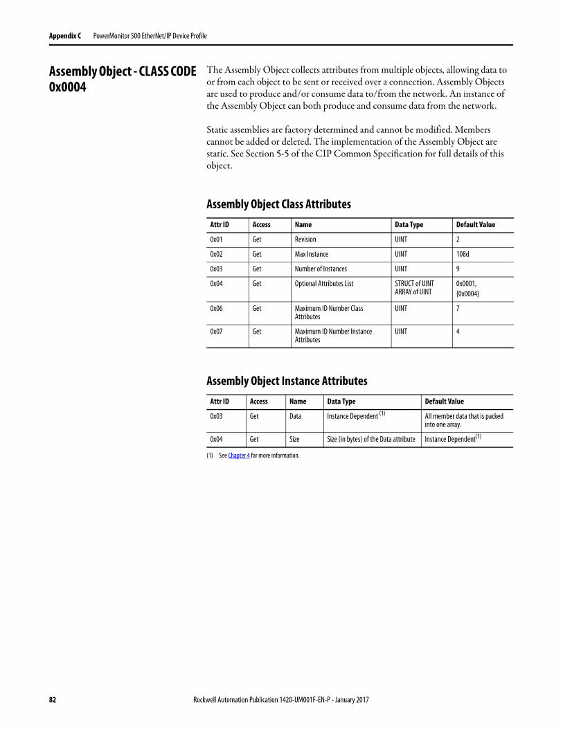
Appendix C PowerMonitor 500 EtherNet/IP Device Profile
Assembly Object - CLASS CODE 0x0004
The Assembly Object collects attributes from multiple objects, allowing data to or from each object to be sent or received over a connection. Assembly Objects are used to produce and/or consume data to/from the network. An instance of the Assembly Object can both produce and consume data from the network.
Static assemblies are factory determined and cannot be modified. Members cannot be added or deleted. The implementation of the Assembly Object are static. See Section 5-5 of the CIP Common Specification for full details of this object.
Assembly Object Class Attributes
Assembly Object Instance Attributes
Attr ID Access Name Data Type Default Value
0x01 Get Revision UINT 2
0x02 Get Max Instance UINT 108d
0x03 Get Number of Instances UINT 9
0x04 Get Optional Attributes List STRUCT of UINT ARRAY of UINT
0x0001,
{0x0004}
0x06 Get Maximum ID Number Class Attributes
UINT 7
0x07 Get Maximum ID Number Instance Attributes
UINT 4
Attr ID Access Name Data Type Default Value
0x03 Get Data Instance Dependent (1)
(1) See Chapter 4 for more information.
All member data that is packed into one array.
0x04 Get Size Size (in bytes) of the Data attribute Instance Dependent(1)
82 Rockwell Automation Publication 1420-UM001F-EN-P - January 2017
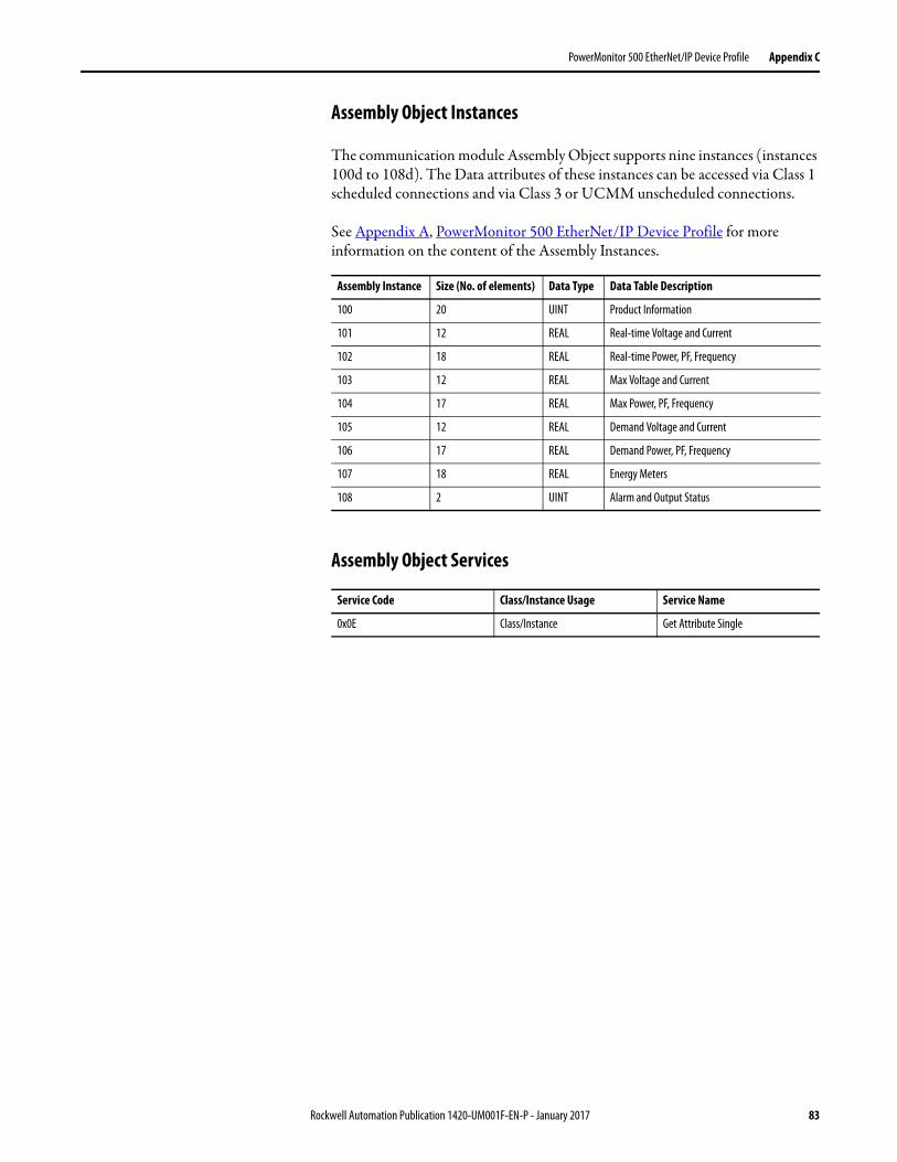
PowerMonitor 500 EtherNet/IP Device Profile Appendix C
Assembly Object Instances
The communication module Assembly Object supports nine instances (instances 100d to 108d). The Data attributes of these instances can be accessed via Class 1 scheduled connections and via Class 3 or UCMM unscheduled connections.
See Appendix A, PowerMonitor 500 EtherNet/IP Device Profile for more information on the content of the Assembly Instances.
Assembly Object Services
Assembly Instance Size (No. of elements) Data Type Data Table Description
100 20 UINT Product Information
101 12 REAL Real-time Voltage and Current
102 18 REAL Real-time Power, PF, Frequency
103 12 REAL Max Voltage and Current
104 17 REAL Max Power, PF, Frequency
105 12 REAL Demand Voltage and Current
106 17 REAL Demand Power, PF, Frequency
107 18 REAL Energy Meters
108 2 UINT Alarm and Output Status
Service Code Class/Instance Usage Service Name
0x0E Class/Instance Get Attribute Single
Rockwell Automation Publication 1420-UM001F-EN-P - January 2017 83
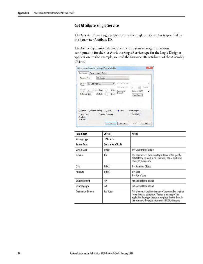
Appendix C PowerMonitor 500 EtherNet/IP Device Profile
Get Attribute Single Service
The Get Attribute Single service returns the single attribute that is specified by the parameter Attribute ID.
The following example shows how to create your message instruction configuration for the Get Attribute Single Service type for the Logix Designer application. In this example, we read the Instance 102 attributes of the Assembly Object.
Parameter Choice Notes
Message Type CIP Generic
Service Type Get Attribute Single
Service Code e (hex) e = Get Attribute Single
Instance 102 This parameter is the Assembly Instance of the specific data table to be read. In this example, 102 = Real-time Power, PF, Frequency
Class 4 (hex) 4 = Assembly Object
Attribute 3 (hex) 3 = Data
4 = Size of data
Source Element N/A Not applicable to a Read
Source Length N/A Not applicable to a Read
Destination Element See Notes This element is the first element of the controller tag that stores the data being read. The tag is an array of the applicable data type the same length as the Attribute. In this example, the tag is an array of 18 REAL elements.
84 Rockwell Automation Publication 1420-UM001F-EN-P - January 2017
PowerMonitor 500 EtherNet/IP Device Profile Appendix C
Connections
The Assembly Object supports both scheduled (Class 1) and unscheduled connections (Class 3 and UCMM). Both connections are used to access instances 100d to 108d of the Assembly Object:
• UDP - Nine Class 1 connections each to the nine Assembly Instances 100 to 108 at 100 ms RPI ran stable
• TCP - Nine Class 3 connections each to the nine Assembly Instances 100 to 108 at 200 ms RPI ran stable
• Both - UDP and TCP can run simultaneously
Heartbeat Instances
With the Assembly Instances shown earlier, the communication module also recognizes two heartbeat instances. A heartbeat instance is a virtual output instance that is specified by devices wishing to establish Input Only and Listen Only Class 1 I/O connections to the communication module. Data cannot be read from or written to a heartbeat instance. The heartbeat instance is merely a programming construct that serves to keep the connection active.
The communication module heartbeat instances are Instance 98 for the Input Only connection and Instance 99 for the Listen Only connection.
Behavior
The purpose of the Assembly Object is to act as a network interface to the PowerMonitor 500 unit data. That data is accessed by various means: Class 1 or Class 3 connections and also with UCMM messages.
Technical Notes This section lists additional technical information about Ethernet network communication.
Parameters
For the EtherNet/IP communication module, set the following parameters by using Programming mode through the base module front panel:
• IP address• Subnet• Gateway• Modbus TCP/IP port• Address Conflict Detect (ACD)
Rockwell Automation Publication 1420-UM001F-EN-P - January 2017 85
Appendix C PowerMonitor 500 EtherNet/IP Device Profile
Modbus TCP/IP
The communication module supports Modbus TCP/IP. The protocol is the same as the PowerMonitor 500 unit with RS-485 (Modbus RTU). See Chapter 4 for protocol details. In this product, only one Modbus TCP/IP connection (one socket) is allowed.
The EtherNet/IP and Modbus TCP/IP do not run concurrently. If ModbusTCP/IP communication occurs, EtherNet/IP communication stops temporarily but recovers in a minute or two.
ACD
If an address conflict is detected from the communication module, then the base module displays ‘ACD Found’. In that case, it is necessary to check the network configuration, resolve the problem, and then cycle control power to the power monitor to re-establish communication.
TCP/IP Port
Default EtherNet/IP ports include the following:• UDP (implicit message): 2222 (0x08AE)• TCP (explicit message): 44818 (0xAF12)
You can reassign the default Modbus TCP/IP port: 502 (0x01F6).
IMPORTANT We recommend that you use Modbus TCP/IP to configure or write to the
PowerMonitor 500 unit and that you use Ethernet/IP to read the PowerMonitor
500 unit.
86 Rockwell Automation Publication 1420-UM001F-EN-P - January 2017
Appendix D
Unit Configuration - Base Firmware Revision 11 and Earlier
Configure with the Display The PowerMonitor™ 500 unit provides menu-based configuration (programming) by using its front panel display. The programming menus let you select parameters to edit, select digits within parameters, and increase or decrease the value of each digit.
Place the unit in Programming mode by pressing Program/select (8) for about 2 seconds. The front panel displays the PASSWORD? menu page 0 in Editing mode. Enter the correct password by using the Up and Down arrows (the default password is 0) and press Program/select. The front panel then displays the CHANGE PAS menu page 10.
See the programming flowchart that begins on page 90 for a view of the organization of programming menus and submenus. Each page is identified with a number, which is displayed in the top right corner. Menu page numbers end in zero, while submenu pages end in 1 through 9. For example, the Change Password page is menu 10. Likewise, the Dmd page is menu 80, and the demand interval Time page is menu 82.
While you are programming the power monitor, the display items and control buttons function one way when you are navigating between menu or submenu pages, and another way when you are editing a menu page.
Rockwell Automation Publication 1420-UM001F-EN-P - January 2017 87
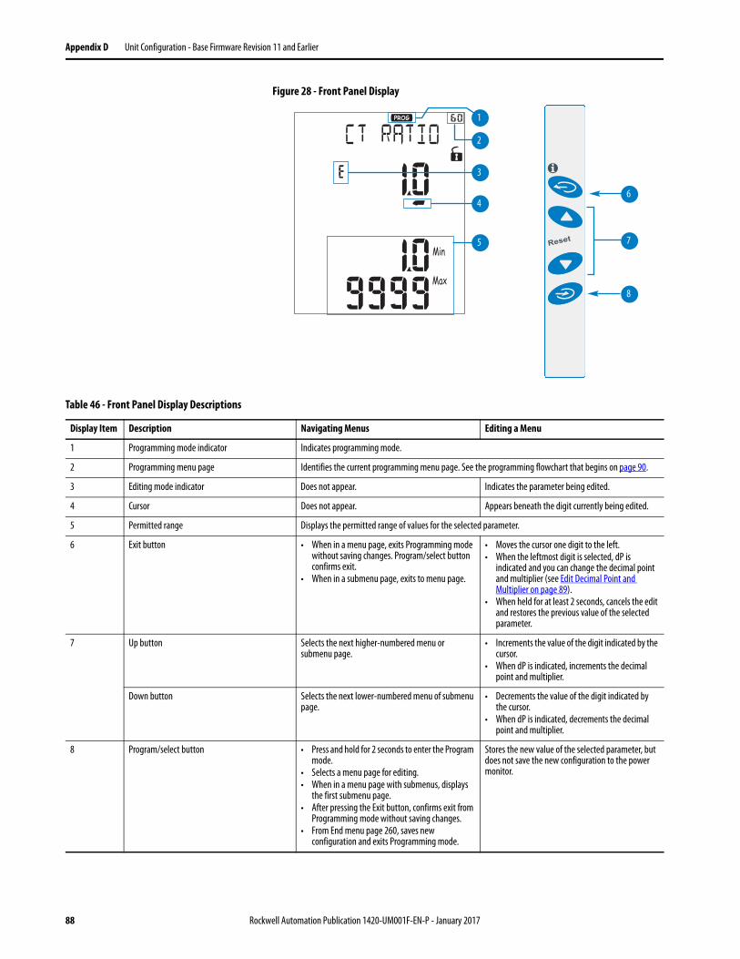
Appendix D Unit Configuration - Base Firmware Revision 11 and Earlier
Figure 28 - Front Panel Display
6
7
8
3
4
5
2
1
Table 46 - Front Panel Display Descriptions
Display Item Description Navigating Menus Editing a Menu
1 Programming mode indicator Indicates programming mode.
2 Programming menu page Identifies the current programming menu page. See the programming flowchart that begins on page 90.
3 Editing mode indicator Does not appear. Indicates the parameter being edited.
4 Cursor Does not appear. Appears beneath the digit currently being edited.
5 Permitted range Displays the permitted range of values for the selected parameter.
6 Exit button • When in a menu page, exits Programming mode without saving changes. Program/select button confirms exit.
• When in a submenu page, exits to menu page.
• Moves the cursor one digit to the left.• When the leftmost digit is selected, dP is
indicated and you can change the decimal point and multiplier (see Edit Decimal Point and Multiplier on page 89).
• When held for at least 2 seconds, cancels the edit and restores the previous value of the selected parameter.
7 Up button Selects the next higher-numbered menu or submenu page.
• Increments the value of the digit indicated by the cursor.
• When dP is indicated, increments the decimal point and multiplier.
Down button Selects the next lower-numbered menu of submenu page.
• Decrements the value of the digit indicated by the cursor.
• When dP is indicated, decrements the decimal point and multiplier.
8 Program/select button • Press and hold for 2 seconds to enter the Program mode.
• Selects a menu page for editing.• When in a menu page with submenus, displays
the first submenu page.• After pressing the Exit button, confirms exit from
Programming mode without saving changes.• From End menu page 260, saves new
configuration and exits Programming mode.
Stores the new value of the selected parameter, but does not save the new configuration to the power monitor.
88 Rockwell Automation Publication 1420-UM001F-EN-P - January 2017
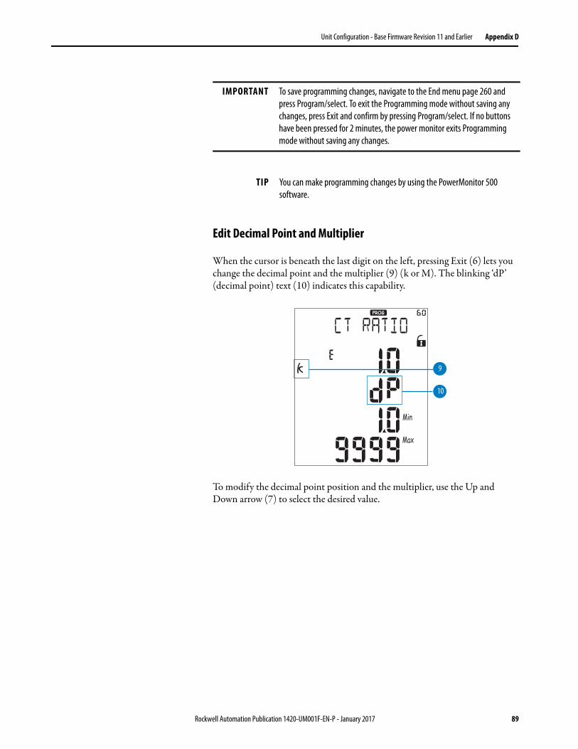
Unit Configuration - Base Firmware Revision 11 and Earlier Appendix D
Edit Decimal Point and Multiplier
When the cursor is beneath the last digit on the left, pressing Exit (6) lets you change the decimal point and the multiplier (9) (k or M). The blinking ‘dP’ (decimal point) text (10) indicates this capability.
To modify the decimal point position and the multiplier, use the Up and Down arrow (7) to select the desired value.
IMPORTANT To save programming changes, navigate to the End menu page 260 and
press Program/select. To exit the Programming mode without saving any
changes, press Exit and confirm by pressing Program/select. If no buttons
have been pressed for 2 minutes, the power monitor exits Programming
mode without saving any changes.
TIP You can make programming changes by using the PowerMonitor 500
software.
10
9
Rockwell Automation Publication 1420-UM001F-EN-P - January 2017 89
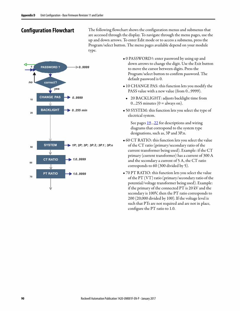
Appendix D Unit Configuration - Base Firmware Revision 11 and Earlier
Configuration Flowchart The following flowchart shows the configuration menus and submenus that are accessed through the display. To navigate through the menu pages, use the up and down arrows. To enter Edit mode or to access a submenu, press the Program/select button. The menu pages available depend on your module type.
• 0 PASSWORD?: enter password by using up and down arrows to change the digit. Use the Exit button to move the cursor between digits. Press the Program/select button to confirm password. The default password is 0.
• 10 CHANGE PAS: this function lets you modify the PASS value with a new value (from 0…9999).
• 20 BACKLIGHT: adjusts backlight time from 0…255 minutes (0 = always on).
• 50 SYSTEM: this function lets you select the type of electrical system.
See pages 19…22 for descriptions and wiring diagrams that correspond to the system type designations, such as, 3P and 3P.n.
• 60 CT RATIO: this function lets you select the value of the CT ratio (primary/secondary ratio of the current transformer being used). Example: if the CT primary (current transformer) has a current of 300 A and the secondary a current of 5 A, the CT ratio corresponds to 60 (300 divided by 5).
• 70 PT RATIO: this function lets you select the value of the PT (VT) ratio (primary/secondary ratio of the potential/voltage transformer being used). Example: if the primary of the connected PT is 20 kV and the secondary is 100V, then the PT ratio corresponds to 200 (20,000 divided by 100). If the voltage level is such that PTs are not required and are not in place, configure the PT ratio to 1.0.
90 Rockwell Automation Publication 1420-UM001F-EN-P - January 2017
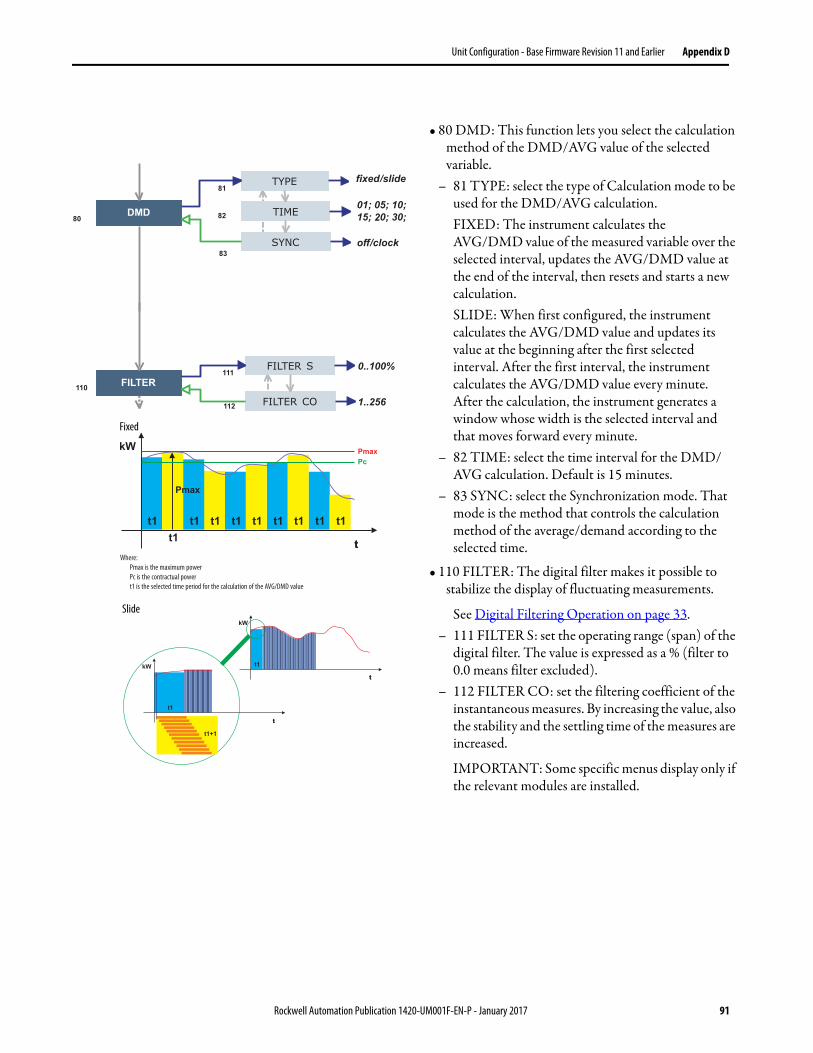
Unit Configuration - Base Firmware Revision 11 and Earlier Appendix D
• 80 DMD: This function lets you select the calculation method of the DMD/AVG value of the selected variable.
– 81 TYPE: select the type of Calculation mode to be used for the DMD/AVG calculation.FIXED: The instrument calculates the AVG/DMD value of the measured variable over the selected interval, updates the AVG/DMD value at the end of the interval, then resets and starts a new calculation.SLIDE: When first configured, the instrument calculates the AVG/DMD value and updates its value at the beginning after the first selected interval. After the first interval, the instrument calculates the AVG/DMD value every minute. After the calculation, the instrument generates a window whose width is the selected interval and that moves forward every minute.
– 82 TIME: select the time interval for the DMD/AVG calculation. Default is 15 minutes.
– 83 SYNC: select the Synchronization mode. That mode is the method that controls the calculation method of the average/demand according to the selected time.
• 110 FILTER: The digital filter makes it possible to stabilize the display of fluctuating measurements.
See Digital Filtering Operation on page 33.– 111 FILTER S: set the operating range (span) of the
digital filter. The value is expressed as a % (filter to 0.0 means filter excluded).
– 112 FILTER CO: set the filtering coefficient of the instantaneous measures. By increasing the value, also the stability and the settling time of the measures are increased.
IMPORTANT: Some specific menus display only if the relevant modules are installed.
Where:
Pmax is the maximum power
Pc is the contractual power
t1 is the selected time period for the calculation of the AVG/DMD value
Fixed
Slide
Rockwell Automation Publication 1420-UM001F-EN-P - January 2017 91
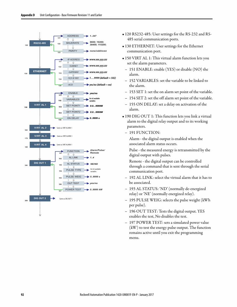
Appendix D Unit Configuration - Base Firmware Revision 11 and Earlier
• 120 RS232-485: User settings for the RS-232 and RS-485 serial communication ports.
• 130 ETHERNET: User settings for the Ethernet communication port.
• 150 VIRT AL 1: This virtual alarm function lets you set the alarm parameters.
– 151 ENABLE: enable (YES) or disable (NO) the alarm.
– 152 VARIABLES: set the variable to be linked to the alarm.
– 153 SET 1: set the on alarm set point of the variable.– 154 SET 2: set the off alarm set point of the variable.– 155 ON DELAY: set a delay on activation of the
alarm.
• 190 DIG OUT 1: This function lets you link a virtual alarm to the digital relay output and to its working parameters.
– 191 FUNCTION: Alarm - the digital output is enabled when the associated alarm status occurs. Pulse - the measured energy is retransmitted by the digital output with pulses. Remote - the digital output can be controlled through a command that is sent through the serial communication port.
– 192 AL LINK: select the virtual alarm that it has to be associated.
– 193 AL STATUS: ‘ND’ (normally de-energized relay) or ‘NE’ (normally energized relay).
– 195 PULSE WEIG: selects the pulse weight (kWh per pulse).
– 196 OUT TEST: Tests the digital output. YES enables the test, No disables the test.
– 197 POWER TEST: sets a simulated power value (kW) to test the energy pulse output. The function remains active until you exit the programming menu.
list of available
variables
list of available
variables
Same as DIG OUT 1
Same as VIRT ALARM 1
Same as VIRT ALARM 1
list of available
variables
-IP ADDRESS
-SUBNET
-GATEWAY
-TCP IP PRT
-ACD
ETHERNET
www.xxx.yyy.zzz
www.xxx.yyy.zzz
www.xxx.yyy.zzz
1…9999 (default = 502)
yes/no (default = no)
Same as VIRT ALARM 1
92 Rockwell Automation Publication 1420-UM001F-EN-P - January 2017
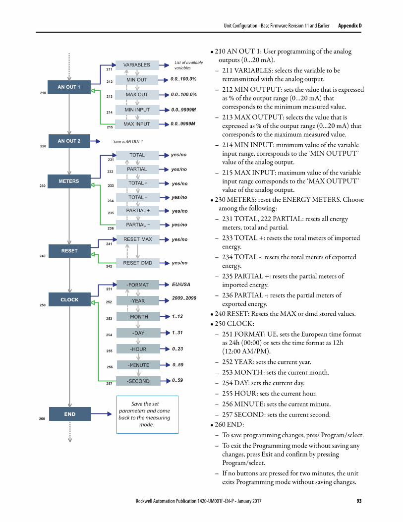
Unit Configuration - Base Firmware Revision 11 and Earlier Appendix D
• 210 AN OUT 1: User programming of the analog outputs (0…20 mA).
– 211 VARIABLES: selects the variable to be retransmitted with the analog output.
– 212 MIN OUTPUT: sets the value that is expressed as % of the output range (0…20 mA) that corresponds to the minimum measured value.
– 213 MAX OUTPUT: selects the value that is expressed as % of the output range (0…20 mA) that corresponds to the maximum measured value.
– 214 MIN INPUT: minimum value of the variable input range, corresponds to the ‘MIN OUTPUT’ value of the analog output.
– 215 MAX INPUT: maximum value of the variable input range corresponds to the ‘MAX OUTPUT’ value of the analog output.
• 230 METERS: reset the ENERGY METERS. Choose among the following:
– 231 TOTAL, 222 PARTIAL: resets all energy meters, total and partial.
– 233 TOTAL +: resets the total meters of imported energy.
– 234 TOTAL -: resets the total meters of exported energy.
– 235 PARTIAL +: resets the partial meters of imported energy.
– 236 PARTIAL -: resets the partial meters of exported energy.
• 240 RESET: Resets the MAX or dmd stored values.• 250 CLOCK:
– 251 FORMAT: UE, sets the European time format as 24h (00:00) or sets the time format as 12h (12:00 AM/PM).
– 252 YEAR: sets the current year.– 253 MONTH: sets the current month.– 254 DAY: sets the current day.– 255 HOUR: sets the current hour.– 256 MINUTE: sets the current minute.– 257 SECOND: sets the current second.
• 260 END: – To save programming changes, press Program/select. – To exit the Programming mode without saving any
changes, press Exit and confirm by pressing Program/select.
– If no buttons are pressed for two minutes, the unit exits Programming mode without saving changes.
Save the set parameters and comeback to the measuring
mode.
List of availablevariables
Same as AN OUT 1
Rockwell Automation Publication 1420-UM001F-EN-P - January 2017 93

Appendix D Unit Configuration - Base Firmware Revision 11 and Earlier
Notes:
94 Rockwell Automation Publication 1420-UM001F-EN-P - January 2017
Index
Numerics485 option 69
AA option 69
about PowerMonitor 500 7access information pages 13
accuracy 8, 75
additional button functions 10
addressModbus 46physical 46
alarm configuration 37
alarm icons 11
analog output specifications 69
analog outputs 21
configuration 36, 61
Bbilling 7buttons 9
additional functions 10descriptions 26, 88
Ccalculation formulas 76
catalog number explanation 5change
decimal point 27, 89multiplier 27, 89
CIP generic 40
class 1 42
comman specifications 70
commands 63
communicationEtherNet⁄IP 8Modbus 8, 45ports 7RS-232 8, 45RS-485 8, 45
communication commands 39
configurable alarms 8configuration 25, 87
alarm 37analog output 36analog outputs communication 61relay outputs communication 62RS-232 communication 60RS-485 communication 60
configuration alarms 60
configuration base unit 59
configuration flow chart 28 … 32, 90 … 93
control 7cost allocation 7
current transformer wiring 17
Ddata tables 49
data types supported 46
decimal point change 27, 89
diagrams,wiring 17
digital filter programming examples 33 … 35
digital filtering operation 33
digital output specifications 68
digital outputs wiring 21
dimensions 8, 15
optional modules 15display 8, 11
alarm icons 11features 11icons 11
display description 26, 88
display specifications 70
Eelectronic data sheet 40
energy metering values 59
energy meters specificationsspecifications
energy meter 70entering password 25, 87
EtherNet/IP communication 39
assembly object 82assembly object instances 83byte order 39common services 83device profile 77explicit messaging 40identity object 77identity object instance attributes 78implicit messaging 42Modbus TCP/IP 45technical notes 85
explicit messaging 40
Ffactory installed options
modules 15wiring 21
FactoryTalk EnergyMetrix 7features 7filter CO 33
filter S 33
formulas 76
front panelbuttons 9, 26, 88indicators 9
functions 7
Rockwell Automation Publication 1420-UM001F-EN-P - January 2017 95
Index
Ggeneral specifications 72
geometric representation 50
ground connection 46
Iicons
alarm 11display 11
IEC vs NEMA diagrams 17
implicit messaging 42
indications 11
indicators 9information access 13
input specifications 67
installation 15, 16
IP65 7, 8isolation between inputs and outputs 73
Lline amplifier 46
list of variables 74 … 75
load profiling 7
Mmain functions specifications 71
menu page numbers 25, 87
message setup 40, 42
Modbusaddress 46commands 63communication 45configure alarms 60configure base unit 59data types supported 46energy metering values 59functions supported 45real-time metering demand 56, 57real-time metering values 52, 53, 54, 55register format 47register maps 51status 65TCP/IP 45
monitoring 7multiplier change 27, 89
Ooptional modules
dimensions 15
PP option specifications 68
panel cut-out 15
password 25, 87
physical address 46
portsEtherNet/IP 7RS-485/RS-232 7
power and power factorgeometric representation 50
power supply 8power supply wiring 21
power systemmonitoring 7
power system control 7PowerMonitor 500
about 7configuration 25, 87cut-out 15dimensions 15features 7functions 7installation 15panel installation 16wiring terminals 16
product information 51
programming mode 25, 87
25, 87protection
IP65 7, 8NEMA 12 8NEMA 4X 8
pulse output specifications 68
Rreal-time metering demand 56, 57
real-time metering values 52, 53, 54, 55
register format 47
register maps 51
relay outputsconfiguration 62
RS-232 45
configuration 60wiring 22
RS-485 45
configuration 60wiring 22
Ssave changes 27, 89
serial communication specifications 69
shielded cable 46
single-phase 8software
FactoryTalk EnergyMetrix 7
96 Rockwell Automation Publication 1420-UM001F-EN-P - January 2017
Index
specifications485 option 69A option 69analog output 69command 70digital output 68display 70energy meters 70general 72input 67isolation between inputs and outputs 73main functions 71P option 68power supply 73pulse output 68relay output 68RS-485 and RS-232 69serial communication 69status indicators 70
status 65
status indicators specifications 70
sub-billing 7
Tthree-phase 8
Vvariables 74 … 75
voltage ranges 8
Wwiring
analog outputs 21digital outputs 21Ethernet 23RS-232 22RS-485 22
wiring diagrams 17
wiring terminals 16
Rockwell Automation Publication 1420-UM001F-EN-P - January 2017 97

Index
Notes:
98 Rockwell Automation Publication 1420-UM001F-EN-P - January 2017

Publication 1420-UM001F-EN-P - January 2017 PN-XXXXXX-XXSupersedes Publication 1420-UM001E-EN-P - March 2016 Copyright © 2017 Rockwell Automation, Inc. All rights reserved. Printed in the U.S.A.
Rockwell Automation SupportUse the following resources to access support information.
Documentation FeedbackYour comments will help us serve your documentation needs better. If you have any suggestions on how to improve this document, complete the How Are We Doing? form at http://literature.rockwellautomation.com/idc/groups/literature/documents/du/ra-du002_-en-e.pdf.
Technical Support Center Knowledgebase Articles, How-to Videos, FAQs, Chat, User Forums, and Product Notification Updates.
https://rockwellautomation.custhelp.com/
Local Technical Support Phone Numbers Locate the phone number for your country. http://www.rockwellautomation.com/global/support/get-support-now.page
Direct Dial Codes Find the Direct Dial Code for your product. Use the code to route your call directly to a technical support engineer.
http://www.rockwellautomation.com/global/support/direct-dial.page
Literature Library Installation Instructions, Manuals, Brochures, and Technical Data.
http://www.rockwellautomation.com/global/literature-library/overview.page
Product Compatibility and Download Center (PCDC)
Get help determining how products interact, check features and capabilities, and find associated firmware.
http://www.rockwellautomation.com/global/support/pcdc.page
.
Rockwell Otomasyon Ticaret A.Ş., Kar Plaza İş Merkezi E Blok Kat:6 34752 İçerenköy, İstanbul, Tel: +90 (216) 5698400
Rockwell Automation maintains current product environmental information on its website at http://www.rockwellautomation.com/rockwellautomation/about-us/sustainability-ethics/product-environmental-compliance.page.
Allen-Bradley, CompactLogix, ControlLogix, FactoryTalk EnergyMetrix, PowerMonitor, Rockwell Automation, Rockwell Software, RSLinx, RSLogix, RSNetWorx, and Studio 5000 Logix Designer are trademarks of
Rockwell Automation, Inc.
Trademarks not belonging to Rockwell Automation are property of their respective companies.