preliminary plan of development for the advanced …
TRANSCRIPT
PRELIMINARY PLAN OF DEVELOPMENT
FOR THE
ADVANCED RAIL ENERGY STORAGE REGULATION
ENERGY MANAGEMENT SYSTEM PROJECT
Submitted to:
Bureau of Land Management Southern Nevada District Office
Renewable Energy Coordination Office
Submitted by:
ARES Nevada, LLC
January 2014

THIS PAGE INTENTIONALLY LEFT BLANK
1 ARES Revised Preliminary Plan of Development January 2014 Advanced Rail Energy Storage - Regulation Energy Management System Project
Table of Contents
1.0 INTRODUCTION ................................................................................................................................. 3
2.0 PROPOSED ACTION ........................................................................................................................... 4
3.0 COMPONENT DESCRIPTIONS ............................................................................................................ 6
Rail Line Corridor and Vehicles ................................................................................................................. 7
Single Track Rail Line Corridor ......................................................................................................... 7
Rail Line Vehicles .............................................................................................................................. 8
Maintenance, Control, and Support Facilities ........................................................................................ 10
Transmission Interconnection Line ......................................................................................................... 11
Project Access Road ................................................................................................................................ 13
4.0 RIGHT-OF-WAY ACQUISITION ......................................................................................................... 15
5.0 PROJECT CONSTRUCTION, OPERATION, AND MAINTENANCE ....................................................... 15
Preconstruction Activities ....................................................................................................................... 15
Engineering Surveys ....................................................................................................................... 15
Cultural Resource Surveys ............................................................................................................. 16
Biological Surveys........................................................................................................................... 16
Construction Activities ............................................................................................................................ 16
Materials ........................................................................................................................................ 17
Project Access Roads ..................................................................................................................... 17
Rail Line .......................................................................................................................................... 18
Rail Line Power Distribution Line and Interconnection ................................................................. 19
Building and Support Facilities ....................................................................................................... 19
Cleanup .......................................................................................................................................... 20
Operation and Maintenance ................................................................................................................... 20
Reclamation ............................................................................................................................................ 21

2 ARES Revised Preliminary Plan of Development January 2014 Advanced Rail Energy Storage - Regulation Energy Management System Project
LIST OF ACRONYMS
ACCC Aluminum Conductor Composite Core
AREMA American Railway Engineering & Maintenance-of-Way Association
ARES Advanced Rail Energy Storage
BLM Bureau of Land Management
CAISO California Independent System Operator
FWS U. S. Fish and Wildlife Service
IEEE Institute of Electrical and Electronics Engineers
IHHA International Heavy Haul Association
kV Kilovolt(s)
MOW Maintenance-of-Way
MW Megawatt(s)
MWH Megawatt Hour
NDOT Nevada Department of Transportation
NDOW Nevada Department of Wildlife
NEPA National Environmental Policy Act
OPGW Optical Ground Wire
POD Plan of Development
REM Regulation Energy Management
ROW Right-of-Way
RUS Rural Utility Services
VEA Valley Electric Association
WECC Western Electricity Coordinating Council

3 ARES Revised Preliminary Plan of Development January 2014 Advanced Rail Energy Storage - Regulation Energy Management System Project
1.0 INTRODUCTION
ARES Nevada, LLC (ARES) is submitting this preliminary Plan of Development (POD) to the Bureau of Land Management (BLM), Southern Nevada District Office, Pahrump Field Office, along with a Standard Form 299 Application for Transportation and Utility Systems and Facilities on Federal Lands for the construction, operation, and maintenance of a proposed Advanced Rail Energy Storage Regulation Energy Management (REM) project. This system is a gravity-based energy storage system utilizing electric shuttle trains operating on a single, steep-grade railroad track to store electric energy in the form of potential energy. The goal is to assist in electricity supply management on a regional electrical grid. The system accomplishes this by using electricity from the grid when electricity is abundant to power the locomotives uphill, then returning electricity to the grid when electricity is needed as the locomotives descend, their motors operating as generators. This system is designed to operate at greater than 80% efficiency for at least 40 years.
ARES proposes to locate this project in the Carpenter Canyon area, east of Pahrump, in Nye and Clark Counties, Nevada (see Figure 1). This project will access the regional electrical grid via a transmission interconnection line to the existing Valley Electric Association (VEA) Gamebird Switch approximately 800 feet east of Nevada State Highway 160 and 2,000 feet west of the existing VEA 230kV transmission line. Figure 2 illustrates the location of the proposed project relative to Pahrump and Nevada State Highway 160. ARES will construct and operate the project in conformity with the approved POD that will be included as part of the Right-of-Way (ROW) grant.
Figure 1. Proposed location of the ARES REM facility.

4 ARES Revised Preliminary Plan of Development January 2014 Advanced Rail Energy Storage - Regulation Energy Management System Project
Figure 2. Proposed location of the ARES REM project ROW.
2.0 PROPOSED ACTION
The proposed action is to construct a 50 Megawattt (MW) capacity, gravity-based energy storage system on approximately 160 acres of BLM managed land east of Nevada State Highway 160, east of Pahrump, Nevada. The construction and operation of the project will provide 12.5 MW hours (MWH) of fast response energy storage necessary to assist in the balancing of electrical supply and demand as highly and unpredictably variable renewable energy is connected to the transmission grid, increasing renewable energy penetration while maintaining grid reliability. The system operates on a closed low-friction automated steel rail line to transport weighted shuttle trains (electric locomotives and rail cars) between different elevations. The upslope (northeast) end of the ROW will begin in Township 20 South, Range 55 East, Section 28. The ROW will run southwest (down-slope) and connect to the existing VEA (NVN-057100) 230kV transmission line ROW, in Township 21 South, Range 54 East, Section 12. The ROW will then align with the VEA ROW until the transmission interconnection line turns southwest to connect to the VEA Gamebird Switch, located in Township 21 South, Range 54 East, Section 3.
The proposed ARES REM Project includes multiple temporary and permanent (long-term) components constructed and operated by ARES. Other components will be constructed and operated by VEA to directly support the project. Brief summaries of those components are provided below with more detailed descriptions and figures provided in subsequent sections of the POD.
Rail Line Corridor: The corridor will consist of a permanent ROW less than six miles long and up to 140 feet wide. The corridor includes the rail line, an access road, an electricity regulation system (parallel power distribution line with track electrification rail or overhead catenary), a short spur rail to be used as

5 ARES Revised Preliminary Plan of Development January 2014 Advanced Rail Energy Storage - Regulation Energy Management System Project
a turnout, and drainage management features fencing. A rail bridge may be required at Carpenter Canyon Road crossing.
Rail Vehicles: Shuttle trains, each comprised of two electric locomotives and two cars carrying concrete masses, will ascend and descend the rail line at slow speeds, to either take electricity off the grid (ascend), or supply electricity to the grid (descend), depending on the immediate electrical demands being placed on the VEA/California Independent System Operator (CAISO) electrical grid.
Operations, Control and Maintenance Facility: A facility will be constructed along the southwestern end of the rail corridor to provide operations, control, and shuttle train maintenance support. This area will widen the rail corridor to 270 feet along the southwestern 2,000 feet of the corridor.
Transmission Interconnection Line: A new 230kV transmission line will be installed and operated by VEA connecting the project to the regional electrical grid. This intertie will include a substation at the southwestern end of the rail line and a new switch yard at the existing VEA Gamebird Switch, less than three miles northwest of the proposed substation location. Multiple alignments are being considered for the line leading to the Switch. A short new segment of line, running southwest from the existing VEA transmission ROW, in which the majority of the proposed transmission interconnection will run, will be constructed to connect the new line to the Gamebird Switch.
Access Road: A new access road connecting the operations, control, and maintenance facility at the southwestern end of the rail corridor to Nevada State Highway 160, possibly including a new interchange at the Highway, will be developed. Multiple alignments are being considered.
Transmission Line Upgrades: The existing VEA 230kV transmission line infrastructure will require upgrades to support the new transmission interconnection line. The support structures currently in place are not able to support this new third line. The approximately 2,000 foot section of transmission distribution line running from the existing VEA 230kV transmission ROW to the Gamebird Switch will be new construction.
Temporary Construction ROW: Laydown yards and other temporary ROW areas will be required and identified prior to the environmental review process.
The dimension for each of these ROW components is listed in Table 1.
ARES is coordinating with Nye County Planning to identify any required local permits, easements or dedications. Additional permits required by other local, state, and federal agencies are being investigated.
6 ARES Revised Preliminary Plan of Development January 2014 Advanced Rail Energy Storage - Regulation Energy Management System Project
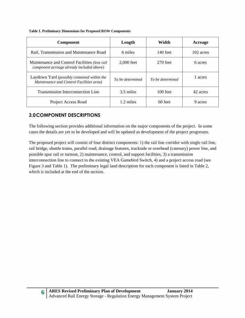
Table 1. Preliminary Dimensions for Proposed ROW Components
Component Length Width Acreage
Rail, Transmission and Maintenance Road 6 miles 140 feet 102 acres
Maintenance and Control Facilities (less rail component acreage already included above)
2,000 feet 270 feet 6 acres
Laydown Yard (possibly contained within the Maintenance and Control Facilities area)
To be determined To be determined 1 acres
Transmission Interconnection Line 3.5 miles 100 feet 42 acres
Project Access Road 1.2 miles 60 feet 9 acres
3.0 COMPONENT DESCRIPTIONS
The following section provides additional information on the major components of the project. In some cases the details are yet to be developed and will be updated as development of the project progresses.
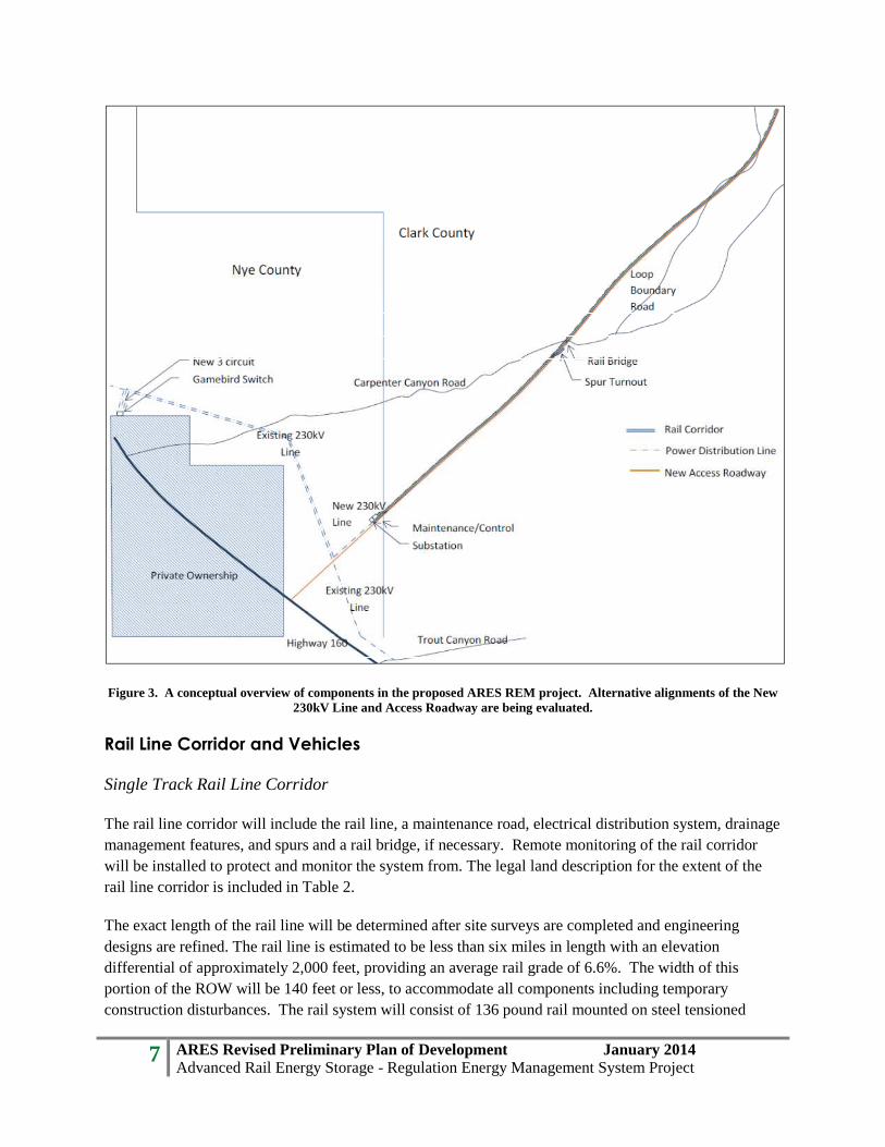
The proposed project will consist of four distinct components: 1) the rail line corridor with single rail line, rail bridge, shuttle trains, parallel road, drainage features, trackside or overhead (catenary) power line, and possible spur rail or turnout, 2) maintenance, control, and support facilities, 3) a transmission interconnection line to connect to the existing VEA Gamebird Switch, 4) and a project access road (see Figure 3 and Table 1). The preliminary legal land description for each component is listed in Table 2, which is included at the end of the section.
7 ARES Revised Preliminary Plan of Development January 2014 Advanced Rail Energy Storage - Regulation Energy Management System Project
Figure 3. A conceptual overview of components in the proposed ARES REM project. Alternative alignments of the New 230kV Line and Access Roadway are being evaluated.
Rail Line Corridor and Vehicles
Single Track Rail Line Corridor
The rail line corridor will include the rail line, a maintenance road, electrical distribution system, drainage management features, and spurs and a rail bridge, if necessary. Remote monitoring of the rail corridor will be installed to protect and monitor the system from. The legal land description for the extent of the rail line corridor is included in Table 2.
The exact length of the rail line will be determined after site surveys are completed and engineering designs are refined. The rail line is estimated to be less than six miles in length with an elevation differential of approximately 2,000 feet, providing an average rail grade of 6.6%. The width of this portion of the ROW will be 140 feet or less, to accommodate all components including temporary construction disturbances. The rail system will consist of 136 pound rail mounted on steel tensioned

8 ARES Revised Preliminary Plan of Development January 2014 Advanced Rail Energy Storage - Regulation Energy Management System Project
concrete rail ties, supported by track ballast comprised of three inch crushed granite or equivalent wear resistant rock. A trackside power distribution line or overhead catenary, running parallel to the track or above the shuttle trains, will be constructed as per final electrical design specification. If utilized in conjunction with the parallel transmission line, a track electrification rail would be powered via an underground conduit from the trackside medium voltage distribution line via trackside step down transformers also located along the length of the rail line.
A rail bridge may be required at the Carpenter Canyon Road grade-crossing. The objective of this bridge would be to maintain a constant grade on the rail line while not impeding access to public lands or movement of wildlife.
A rail line turnout, or spur line, to allow shuttle cars to be re-sequenced on the main rail line will also be included. The location of this spur line has not yet been determined, but it will be contained within the proposed ROW and be less than 1,000 feet in length.
Table 2. Rail Line Corridor Legal Land Description
Township and Range Section Number Aliquot Part
T. 21 S, R. 54 E. 12 SE ¼ T. 21 S., R. 55 E. 7 NW ¼ T. 21 S., R. 55 E. 6 SE ¼ and NE 1/4 T. 21 S., R. 55 E. 5 NW ¼ T. 20 S., R. 55 E. 32 SW ¼, SE ¼ and NE ¼ T. 20 S., R. 55 E. 33 NW ¼ T. 20 S., R. 55 E. 28 NE ¼
Rail Line Vehicles
Approximately 17 shuttle trains will be located on the single track. Each shuttle train may be comprised of two electric locomotives weighing approximately 220 tons each, and two cars with concrete masses, weighing approximately 150 tons each. The shuttles are propelled by high-efficiency regenerative traction drive rail-car chassis. The facility will be compliant with Institute of Electrical and Electronics Engineers (IEEE) 519 generation equipment standards.
Rapid detection and remediation of failures via redundant speed, location, thermal, visual, and vibration sensors, will operate on each shuttle for safety control.
Although each shuttle has the potential to reach 21 miles per hour, the average speed for each will be approximately 15 miles per hour.
Figures 4, 5, and 6, illustrate potential organization alternatives of project components within the rail line corridor. The width on this component of the ROW may be reduced as construction plans are refined and site surveys are conducted. The maintenance and control facilities section of the ROW will be approximately 270 feet wide, running 2,000 feet along the down-slope (southwest) end of the rail line corridor.

9 ARES Revised Preliminary Plan of Development January 2014 Advanced Rail Energy Storage - Regulation Energy Management System Project
Figure 4. Illustration of a potential configuration of the rail corridor components within the proposed ROW should an adjacent power distribution line be used, rather than an overhead catenary. The illustration does not include possible
additional width to encompass construction footprint.
Figure 5. Illustration of a potential configuration of the rail corridor components within the proposed ROW should development plans include the catenary overhead line rather than an adjacent power distribution line.
Drainage
Poles planned to be no more than 50 feet.
Shuttle trains will be 10 – 12 feet tall.
Shuttle trains with overhead catenary will be 15 – 20 feet tall.
10 ARES Revised Preliminary Plan of Development January 2014 Advanced Rail Energy Storage - Regulation Energy Management System Project
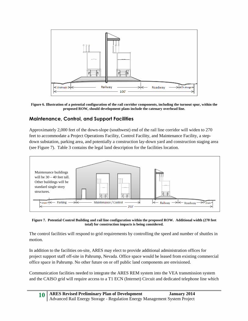
Figure 6. Illustration of a potential configuration of the rail corridor components, including the turnout spur, within the proposed ROW, should development plans include the catenary overhead line.
Maintenance, Control, and Support Facilities
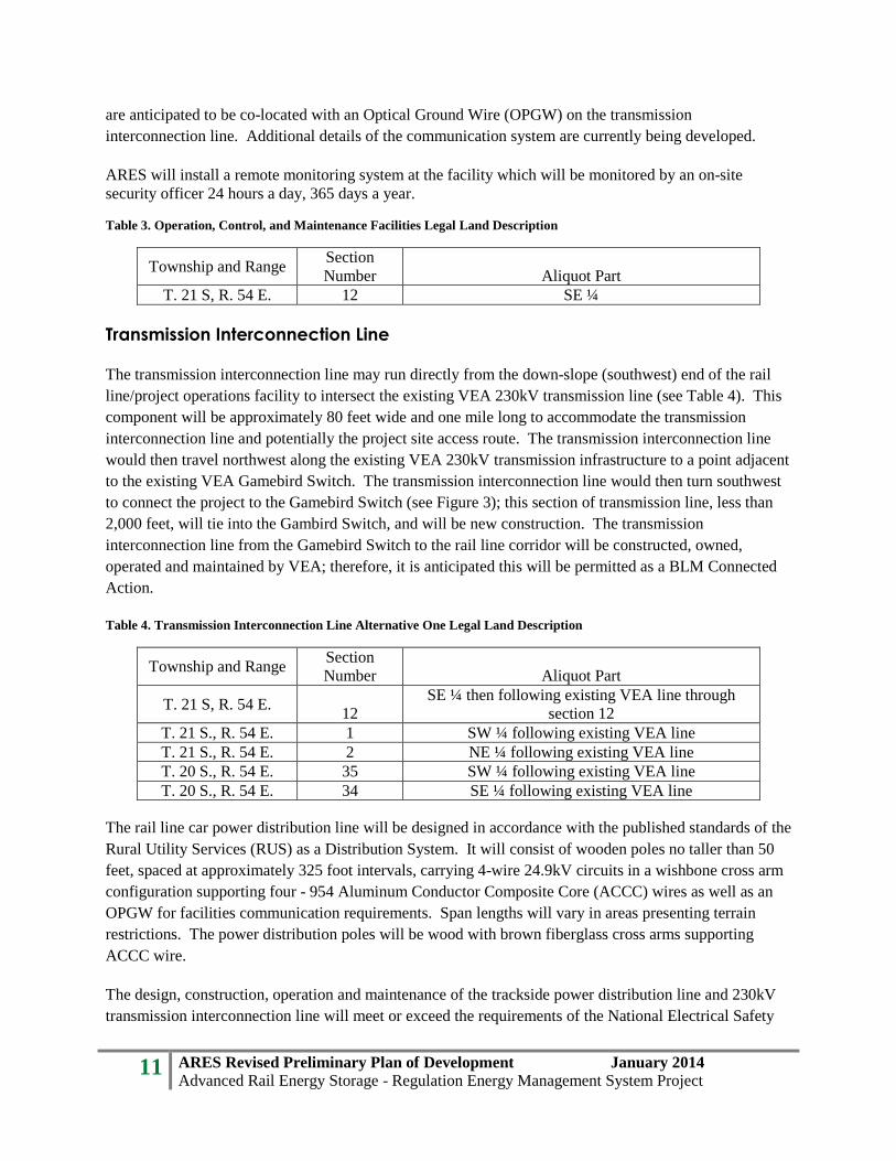
Approximately 2,000 feet of the down-slope (southwest) end of the rail line corridor will widen to 270 feet to accommodate a Project Operations Facility, Control Facility, and Maintenance Facility, a step-down substation, parking area, and potentially a construction lay-down yard and construction staging area (see Figure 7). Table 3 contains the legal land description for the facilities location.
Figure 7. Potential Control Building and rail line configuration within the proposed ROW. Additional width (270 feet total) for construction impacts is being considered.
The control facilities will respond to grid requirements by controlling the speed and number of shuttles in motion.
In addition to the facilities on-site, ARES may elect to provide additional administration offices for project support staff off-site in Pahrump, Nevada. Office space would be leased from existing commercial office space in Pahrump. No other future on or off public land components are envisioned.
Communication facilities needed to integrate the ARES REM system into the VEA transmission system and the CAISO grid will require access to a T1 ECN (Internet) Circuit and dedicated telephone line which
Maintenance buildings will be 30 – 40 feet tall. Other buildings will be standard single story structures.
11 ARES Revised Preliminary Plan of Development January 2014 Advanced Rail Energy Storage - Regulation Energy Management System Project
are anticipated to be co-located with an Optical Ground Wire (OPGW) on the transmission interconnection line. Additional details of the communication system are currently being developed.
ARES will install a remote monitoring system at the facility which will be monitored by an on-site security officer 24 hours a day, 365 days a year.
Table 3. Operation, Control, and Maintenance Facilities Legal Land Description
Township and Range Section Number Aliquot Part
T. 21 S, R. 54 E. 12 SE ¼
Transmission Interconnection Line
The transmission interconnection line may run directly from the down-slope (southwest) end of the rail line/project operations facility to intersect the existing VEA 230kV transmission line (see Table 4). This component will be approximately 80 feet wide and one mile long to accommodate the transmission interconnection line and potentially the project site access route. The transmission interconnection line would then travel northwest along the existing VEA 230kV transmission infrastructure to a point adjacent to the existing VEA Gamebird Switch. The transmission interconnection line would then turn southwest to connect the project to the Gamebird Switch (see Figure 3); this section of transmission line, less than 2,000 feet, will tie into the Gambird Switch, and will be new construction. The transmission interconnection line from the Gamebird Switch to the rail line corridor will be constructed, owned, operated and maintained by VEA; therefore, it is anticipated this will be permitted as a BLM Connected Action.
Table 4. Transmission Interconnection Line Alternative One Legal Land Description
Township and Range Section Number Aliquot Part
T. 21 S, R. 54 E. 12
SE ¼ then following existing VEA line through section 12
T. 21 S., R. 54 E. 1 SW ¼ following existing VEA line T. 21 S., R. 54 E. 2 NE ¼ following existing VEA line T. 20 S., R. 54 E. 35 SW ¼ following existing VEA line T. 20 S., R. 54 E. 34 SE ¼ following existing VEA line
The rail line car power distribution line will be designed in accordance with the published standards of the Rural Utility Services (RUS) as a Distribution System. It will consist of wooden poles no taller than 50 feet, spaced at approximately 325 foot intervals, carrying 4-wire 24.9kV circuits in a wishbone cross arm configuration supporting four - 954 Aluminum Conductor Composite Core (ACCC) wires as well as an OPGW for facilities communication requirements. Span lengths will vary in areas presenting terrain restrictions. The power distribution poles will be wood with brown fiberglass cross arms supporting ACCC wire.
The design, construction, operation and maintenance of the trackside power distribution line and 230kV transmission interconnection line will meet or exceed the requirements of the National Electrical Safety
12 ARES Revised Preliminary Plan of Development January 2014 Advanced Rail Energy Storage - Regulation Energy Management System Project
Code (NESC), U.S. Department of Labor, Occupational Safety and Health Standards and ARES’s requirements for safety.
Based on Avian Power Line Interaction Committee recommendations (Avian Power Line Interaction Committee, 1996), adequate spacing between conductors will be implemented. In addition, shield wire will be grounded at regular intervals and bird diverters and covers will be used as needed.
An upgrade of the existing VEA 230kV transmission line connecting to the existing VEA Gamebird Switch will require new transmission poles supporting nine - 954 ACCC wires at 230kV, a single OPGW for telemetry, and grounding. The new incremental VEA transmission poles will be brown weathered steel as per the existing VEA transmission system construction. Materials will be provided by permitted commercial sources.
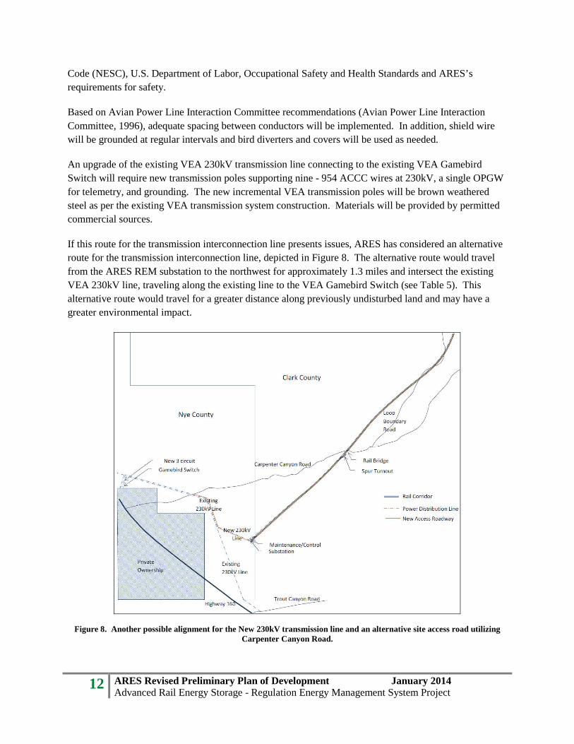
If this route for the transmission interconnection line presents issues, ARES has considered an alternative route for the transmission interconnection line, depicted in Figure 8. The alternative route would travel from the ARES REM substation to the northwest for approximately 1.3 miles and intersect the existing VEA 230kV line, traveling along the existing line to the VEA Gamebird Switch (see Table 5). This alternative route would travel for a greater distance along previously undisturbed land and may have a greater environmental impact.
Figure 8. Another possible alignment for the New 230kV transmission line and an alternative site access road utilizing Carpenter Canyon Road.

13 ARES Revised Preliminary Plan of Development January 2014 Advanced Rail Energy Storage - Regulation Energy Management System Project
Table 5. Transmission Interconnection Line Alternative Two Legal Land Description
Township and Range Section Number Aliquot Part
T. 21 S, R. 54 E. 12
NE ¼, following existing VEA line through section 12
T. 21 S., R. 54 E. 1 SW ¼ following existing VEA line T. 21 S., R. 54 E. 2 NE ¼ following existing VEA line T. 20 S., R. 54 E. 35 SW ¼ following existing VEA line T. 20 S., R. 54 E. 34 SE ¼ following existing VEA line
ARES is currently in the planning phase with VEA to develop an interconnection agreement to tie this project into their existing Gamebird Switch. This will allow ARES and VEA to utilize the existing Gamebird Switch and control facility for location and control of the ARES REM substation transformer and interconnection.
Project Access Road
Existing roads may provide access for project construction, operation, and maintenance, or a new route would be constructed for more direct access to the VEA existing transmission ROW and Nevada State Highway 160. A proposed project access road would extend directly from the down-slope (southwest) end of the rail line, follow the existing slope of the land, intersect with Nevada State Highway 160, approximately 1,000 feet south of Mabes Street, in Township 21 South, Range 54 East, Section 13, as shown in Figure 3 and described in Table 6. This 60-foot-wide ROW (where not co-located with the transmission interconnection line) component would contain the access road and road construction activities. Nevada Department of Transportation (NDOT) will be contacted to obtain approval for and coordinate the construction of the access road intersection with Nevada State Highway 160.
Table 6. Project Access Road Alternative One Legal Land Description
Township and Range Section Number Aliquot Part
T. 21 S, R. 54 E. 12 SE ¼ T. 21 S., R. 54 E. 13 NE ¼
Should this direct route to Nevada State Highway 160 prove problematic or potentially produce a significant environmental impact, ARES has considered alternative routes. The first alternative route would travel approximately one-quarter mile from the southwest terminus of the rail line corridor to intersect the existing VEA 230kV transmission line access road (see Figure 8). The access road would then turn to the northwest to travel along the existing transmission maintenance road for approximately three-quarters of one mile to connect to Carpenter Canyon Road, which has an established intersection with Nevada State Highway 160. The legal land description for this route would be the same as that for transmission interconnection line alternative two (see Table 5). This route is not considered to be ideal due to several factors, specifically, the number and size of construction vehicles needing to travel the route during the construction phase would not be supported by the existing maintenance road and it would require extensive grading, widening, and the addition of culverts or other water diversions, all of which would create substantial disturbances.

14 ARES Revised Preliminary Plan of Development January 2014 Advanced Rail Energy Storage - Regulation Energy Management System Project
A second alternative route would travel approximately one-quarter mile from the southwest terminus of the rail line corridor to intersect the existing VEA 230kV transmission line access road (see Figure 9). The access road would then turn to the southeast to travel along an existing transmission maintenance road for approximately 1.2 miles to connect to Trout Canyon Road, which has an established intersection with Nevada State Highway 160. The legal land description for this route is included in Table 7. This route is not considered to be ideal for the same factors identified above in the first access route alternative, Carpenter Canyon Road (see Figure 8).
Table 7. Project Access Road Alternative Three Legal Land Description
Township and Range Section Number Aliquot Part
T. 21 S, R. 54 E. 12 SE ¼ T. 21 S., R. 54 E. 13 NE ¼ T. 21 S., R. 54 E. 18 SW ¼
Figure 9. Alternative access road from Nevada State Highway 160, via Trout Canyon Road.

15 ARES Revised Preliminary Plan of Development January 2014 Advanced Rail Energy Storage - Regulation Energy Management System Project
4.0 RIGHT-OF-WAY ACQUISITION
New land leases and ROW will be required for the proposed project. A grant for the use of up to 155 acres of federal lands administered by the BLM has been requested. No additional permanent access requirements are anticipated. No state or private lands will be accessed.
As a result of the proposed action, VEA will be required to upgrade the transmission line support structure from where the ARES REM transmission interconnection line meets the existing VEA 230kV transmission line and travels to the Gamebird Switch, approximately 3.5 miles northwest of the project operations facility (see Figure 9).
The proposed ROW alignment intersects the West Wide Energy Corridor (Section 368) at the down-slope (southwestern) end. Portions of the facilities area and transmission interconnection line lie within the corridor.
5.0 PROJECT CONSTRUCTION, OPERATION, AND MAINTENANCE
The following section generally describes the activities anticipated to occur before and during project construction and throughout operation and maintenance of the project. Mitigation measures and lease agreement stipulations to be developed in cooperation with the BLM (see Appendix A) will be incorporated as part of the standard operating procedures.
Preconstruction Activities
Engineering Surveys
The BLM National Environmental Policy Act (NEPA) process will determine the preferred alignment for the project. Preliminary surveys and other investigations will be completed after a preferred alignment is selected by the BLM during the NEPA process, and on-the-ground investigations will be completed to accurately locate the preliminary centerline of the ROW within the selected alternative. The exact centerline will be chosen to best implement design criteria, minimize environmental impacts, and satisfy the mitigation measures in the NEPA compliance document to be developed. Detailed surveying and final design drawings will be developed after the NEPA process determines the most appropriate alternative. Required permits to conduct surveys on federal lands will be obtained. ARES is preparing to conduct engineering site surveys in consultation with rail design civil engineering consultants J.L. Patterson & Associates, Inc. and TRAMMCO, LLC, or other qualified entities. These more precise and detailed surveys conducted after the NEPA review will establish the exact project centerline, locations of drainage features, and address soil and geotechnical considerations of hydrology and hydraulics, critical drainage areas, climate induced track stability issues, and the anticipated Carpenter Canyon Road crossing.
Structure locations will be flagged and staked, and the proposed centerline will be flagged and staked where necessary.

16 ARES Revised Preliminary Plan of Development January 2014 Advanced Rail Energy Storage - Regulation Energy Management System Project
Cultural Resource Surveys
A reputable archaeological contractor will survey the proposed route as part of the NEPA process. Any cultural property potentially directly or indirectly impacted will be evaluated and determined for eligibility through the BLM Section 106 consultation process. Project engineers will work with BLM archaeologists during the NEPA process and beyond to avoid or minimize impacts to any identified cultural resources.
Biological Surveys
The Mojave desert tortoise will require special consideration in consultation with BLM, Nevada Department of Wildlife (NDOW), and U.S. Fish and Wildlife Service (FWS). Specific mitigation measures for biological resources will be developed as part of the environmental evaluation. If necessary, additional surveys or Section 7 consultation will be supported through the BLM during the NEPA process.
As requested by the BLM, disturbance of special status plants (e.g. cacti, yucca, etc.) will be avoided during construction, to the extent possible. Prior to construction, if requested, native plants requiring consideration by the BLM will be flagged in areas of potential surface disturbance. Native plant surveys will be conducted in spring 2014. Per Nevada Revised Statutes, potentially impacted yucca and cacti will be mitigated for according to current BLM and/or Nevada Division of Forestry requirements. All other vegetation removed during construction will be disposed of in accordance with BLM guidelines.
Construction Activities
Construction will involve the earth moving, drainage provisions, and placement of materials typical of service roadway and railway alignment construction, and the construction of operations buildings, power transmission line, and rail line. The railway track roadbed, track with third rail if utilized, rail-side power distribution line or catenary, and parallel service road will be built simultaneously. Detailed site plans have not yet been completed; therefore, figures are currently estimates based on initial preliminary site plans. Preliminary site plans will be developed once initial centerline surveys have been completed. Detailed site plans will be developed after NEPA surveys and reviews have been completed.
Typical materials include Type 2 road gravel, concrete, asphalt and crushed ballast stone, to be obtained from commercial sources using existing, permitted sources.
Construction of the power distribution and transmission interconnection lines involve placing foundations, erecting poles, stringing wire, tying in, testing and commissioning; the special equipment required includes excavators, cranes and wire-stringing trucks.
Buildings will require normal foundation preparation, pouring of slab and footers, and erection of pre-fabricated steel buildings, using lifts, cranes, and fork trucks.

17 ARES Revised Preliminary Plan of Development January 2014 Advanced Rail Energy Storage - Regulation Energy Management System Project
Temporary use areas inside the ROW such as temporary parking and construction lay-down yard(s), will be determined at a later date and will be provided by the construction contractor. No additional laydown yards outside the proposed ROW are anticipated.
The total workforce is dependent on scheduling, but a reasonable estimate if all construction activities occur simultaneously is 100 to 125 workers present at the jobsite. Temporary parking required for construction workers will be identified within the ROW, with the assistance of the construction contractor.
The clearing and grading plan has not yet been developed as it will depend on the detailed site development plans to be prepared by J. L. Patterson & Associates, or other qualified entities, and will follow the normal, approved BLM, Nye County, Clark County, and Nevada Division of Environmental Protection requirements regarding runoff, potential pollution issues, and disposal sites and methods. Engineering plans, as required by BLM, the Army Corps of Engineers, and others, will be developed by ARES. Grading will be minimized where possible to reduce mitigation requirements.
Materials
Sand, gravel and other materials generated from cut and fill activities within the project will be used for road construction to the extent possible. All necessary materials not collected from the site will be purchased from a permitted commercial source. Rail roadbed ballast and road material sourcing is still subject to engineering specification and procurement standards review.
Project Access Roads
Rail line and transmission line construction requires the movement of vehicles along the ROW. For the proposed project, existing access roads will be utilized whenever possible, although new access road construction may be necessary, as detailed in Section 3.0 Component Descriptions. Upon completion of construction, all access roads which have the sole purpose of construction access will be reclaimed according to current BLM standards.
Site access and maintenance roads will be surfaced with Type 2 Gravel and constructed in accordance with Nye County requirements for Type 2 Gravel Road construction, dependent upon the type and number of anticipated construction vehicles necessary for completion of the project. Permitted commercial vendors will supply the materials for roadbeds. Mitigation measures to reduce impacts during construction and use will be implemented, as detailed in Appendix A. The maximum grade of the access road will be 8%. Requirements and general locations of drainage ditches and culverts will be determined during initial engineering site surveys to be evaluated and surveyed during the NEPA review process. Subsequent design drawings will be develop after NEPA evaluation and detailed engineering surveys.
To the extent that on-site native soil and rock from cut activities is not acceptable for use as crushed three inch rail roadbed ballast or Type 2 gravel road building aggregates, this material will be trucked in from existing permitted vendors in Nye, Clark or San Bernardino County.
18 ARES Revised Preliminary Plan of Development January 2014 Advanced Rail Energy Storage - Regulation Energy Management System Project
Rail Line
The railway infrastructure will adhere to minimum standards per the Recommended Practices in the American Railway Engineering & Maintenance-of-Way Association (AREMA) Manual of Railway Engineering (latest); the maximum engineering standards will be based on those recommended in the publication “Guidelines to Best Practices for Heavy Haul Railway Operations - Infrastructure Construction and Maintenance Issues,” published in 2009 by the International Heavy Haul Association (IHHA). We also expect to adopt some promising practices presently under test at the American Association of Railroad’s Transportation Test Center, Inc., Pueblo, Colorado, related to rail and ballast/subgrade life. These improved practices are not as yet codified in any of the current published standards and/or recommended practices. The order of construction generally is:
• Prepare roadbed, spread base ballast (ballast spreader machine). • Distribute and space ties (tie distributing). • Weld and thread rail onto ties (rail threader, welding machine). • Clip rail (clip applicator machines). • Install turnouts (cranes). • Spread additional ballast (special trailer and dump trucks). • Raise transmission line and tamp the track (ballast tamping and dressing machines). • Install third rail (trackside power distribution line) and brackets or overhead caternary lines,
connect power wires.
Track construction uses common construction equipment such as boom trucks, low-bed trucks, high-lifts, rubber-tired loaders, rubber-tired hydraulic cranes, and dozers, plus specialized equipment such as tie distributing spreaders, rail threaders, a portable rail welding machine, and tamping and ballast handling/dressing equipment.
The existing native topsoil will be moved and/or removed, primarily with scrapers and other heavy equipment such as bulldozers, loaders and excavators, and stored for future use in the restoration of disturbed areas. Much of the remainder of this material will be recycled as road topping, parking lot surface, and fill. Topsoil will be salvaged for reclamation activities occurring at a later date. Hot-mix asphalt may be required along any areas of the railway roadbed that are subject to groundwater seepage (see Figure 10). Groundwater interactions are not expected due to the depth of the water table in this area, and will be confirmed through geotechnical surveys.

19 ARES Revised Preliminary Plan of Development January 2014 Advanced Rail Energy Storage - Regulation Energy Management System Project
Figure 10. Conceptual plan for a standard railway roadbed.
Trackside Power Distribution Line and Interconnection
Surveying and routing of the rail line and adjacent power distribution line will assist in identifying any areas of poor soil stability. If soil conditions are unsuitable for installation of poles at specified locations, ARES’s contractor will notify the Project Engineer and the BLM of the conditions present. If possible, the issue will be remedied through relocations of the pole up-line or down-line from the previously specified location.
At each structure site, areas will be needed to stage and facilitate the operation of equipment. A temporary construction disturbance area may be necessary within the proposed ROW. Excavations for poles will be made with power equipment. Where the soil conditions permit, a vehicle-mounted power auger or backhoe will be used. If necessary, the foundation holes may be excavated by drilling. After the hole is augered, poles will be set, backfilled, and tamped using existing soils. Remaining soils and salvaged topsoil will be spread on the ground, and BLM approved reclamation activities will be conducted. Tower and foundation materials will be determined based on final design specifications. Materials will likely consist of gravel or concrete. Alternatively, depending on final design, no foundation may be necessary.
Building and Support Facilities
Structures will be pre-fabricated steel frame buildings on reinforced concrete slabs. The clearing of natural vegetation will be required. Topsoil will be salvaged for future reclamation activities; unused topsoil will be disposed of as required. Selective clearing will be performed where necessary for electrical clearance, line reliability, and construction and maintenance operations. The ROW will not be chemically treated unless necessary to comply with requirements of a permitting agency.

20 ARES Revised Preliminary Plan of Development January 2014 Advanced Rail Energy Storage - Regulation Energy Management System Project
A step-down substation may be located in this component of the ROW, or it may be located within the existing VEA 230kV transmission ROW where the transmission interconnection line becomes co-located with the existing VEA 230kV line. Constructing this facility within the proposed ARES REM ROW will allow for an increased transmission line support pole spacing (using fewer poles), increase efficiency of the project by reducing transmission line electrical loss, and will not construct a feature within the VEA ROW inconsistent with the existing visual form of that corridor. The final location for this facility will be determined after consultations with the BLM and VEA, and further determination of system engineering requirements.
Additional miscellaneous support service locations, including potable water, wastewater, outside lighting, emergency power, fire prevention measures, parking facilities, and storm drains will be detailed in subsequent updates to this POD to allow for NEPA review, and refined during the detailed site engineering survey stage.
Cleanup
Construction sites, material storage yards, and access roads will be kept in an orderly condition throughout the construction period. Refuse and trash, including stakes and flags, will be removed from the sites and disposed of in an approved manner. No construction equipment oil or fuel will be drained on the ground. Oils or chemicals will be hauled to an approved site for disposal. No open burning of construction trash will occur on BLM managed lands.
Operation and Maintenance
It is anticipated that the facility will be staffed seven days a week, 24 hours a day, for possibly 40 years. Weekday day shifts would be staffed by five personnel including a control/operator, a security officer, a general manager, maintenance workers and administrative worker. During the night, graveyard, and weekends, shifts may be staffed by three personnel including a control/operator and a security officer.
Inspection and maintenance schedules are under the supervision of the Maintenance Manager who, with his staff, will develop the schedules necessary for the various elements of the operating system based on the recommendation of the various manufacturers and suppliers of the equipment, and based on best practices recommended by organizations such as the American Railway Engineering and Maintenance-of-Way Association, IHHA, American Association of State Highway and Transportation Officials, NDOT, Electric Utility Distributers Association, Institute of Electrical and Electronics Engineers, etc.
The track and roadway will be inspected daily, possibly employing robotic equipment that can work 24 hours a day, seven days a week, without direct manual control. The inspection criteria will be, at a minimum, based on Title 49 CRF 213 Track Safety Standards as published in the Federal Register (latest), supplemented by recommendations of the IHHA and in-house developed criteria based on best practices from a world-wide network of specialized, heavy-haul railroad operations. There will be an internal process for automatic evaluation of inspection results data, tied into a system to generate work orders that will direct the Maintenance of Way (MOW) Department to repair or replace any defective guideway elements. The MOW Department will operate on a proactive basis to minimize the possibility of guideway components slipping below the State of Good Repair, by grinding rail, correcting surface

21 ARES Revised Preliminary Plan of Development January 2014 Advanced Rail Energy Storage - Regulation Energy Management System Project
anomalies, ultrasound testing of rail, etc., based on the inspection data and a planning forecast program that prevents any serious exceptions from developing.
The shuttle vehicle component manufacturers will provide the rail vehicle inspection process and procedures.
The 230kV transmission interconnection line and 24.9kV trackside power distribution system will be inspected, operated, and maintained by VEA.
As part of standard operating procedures, standard mitigation measures (Appendix A) will be implemented throughout the project in order to reduce potential adverse environmental impacts. Most of the impacts are short term and generally occur during the construction period. Project design and implementation of site-specific or selectively recommended mitigation measures will minimize the effect of the project where the potential for long-term adverse impacts may occur.
Reclamation
At the end of project life, all structures will be removed by ARES and disposed of using current standards for demolition and disposal in Nevada. Railways will be completely removed and the land reclaimed according to current agency requirements, including but not limited to BLM standards. The disturbed surfaces will be restored to the original contour of the land surface to the extent determined by the BLM. Appropriate site-specific seed mixes will be used where conditions vary. Salvaged native plants will be used for revegetation, if appropriate, along with seeding using BLM-recommended seed mixes. All materials will be stored and disposed of in an approved manner.

Appendix A
Mitigation Measures
(to be developed in cooperation with the BLM)