printing from undefined - musicautos.com · disconnect transmission cooler lines ... disconnect the...
TRANSCRIPT

1999-2000 ENGINES
2.5L 4-Cylinder
ENGINE IDENTIFICATION
Engine is identified by the eighth character of Vehicle Identification Number (VIN). VIN is stamped on a metal tag, and is visible through windshield on driver's side. VIN is also located on the Safety Compliance Certification Label on edge of driver's door.
VIN ENGINE CODE
ADJUSTMENTS
VALVE CLEARANCE
TROUBLE SHOOTING
To trouble shoot mechanical engine components, see appropriate table in TROUBLE SHOOTING article in GENERAL INFORMATION.
REMOVAL & INSTALLATION
FUEL PRESSURE RELEASE
Remove fuel tank filler cap to release pressure. Remove Schrader valve cap from fuel rail. See Fig. 1 . Connect fuel pressure gauge to Schrader valve and release fuel into a suitable container.
NOTE: For repair procedures not covered in this article, see ENGINE OVERHAUL PROCEDURES article in GENERAL INFORMATION.
Engine Code2.5L SOHC SFI C
NOTE: Hydraulic valve lash adjusters and roller followers are used. Valves are not adjustable.
CAUTION: When battery is disconnected, vehicle computer and memory systems may lose memory data. Driveability problems may exist until computer systems have completed a relearn cycle. See COMPUTER RELEARN PROCEDURES article in GENERAL INFORMATION before disconnecting battery.
NOTE: For reassembly reference, label all electrical connectors, vacuum hoses and fuel lines before removal. Also place mating marks on engine hood before removal.
2000 Mazda B2500 SE
1999-2000 ENGINES 2.5L 4-Cylinder
2000 Mazda B2500 SE
1999-2000 ENGINES 2.5L 4-Cylinder
MUSICAUTOS.COM
Lunes, 21 de Mayo de 2007 01:26:58 p.m. Page 1 © 2005 Mitchell Repair Information Company, LLC.
MUSICAUTOS.COM
Lunes, 21 de Mayo de 2007 01:27:06 p.m. Page 1 © 2005 Mitchell Repair Information Company, LLC.

Fig. 1: Locating Fuel Pressure Release Valve Courtesy of FORD MOTOR CO.
Alternate Method
Disconnect fuel pump relay. Start engine and run until engine stalls. Crank engine for an additional 20 seconds to ensure all pressure has been released.
COOLING SYSTEM BLEEDING
Fill cooling system with 50/50 mixture of coolant and water. Set heater controls to maximum heat. Start engine and allow to idle until normal operating temperature is reached. Turn engine off and allow to cool. Check coolant level and fill if necessary.
2000 Mazda B2500 SE
1999-2000 ENGINES 2.5L 4-Cylinder
MUSICAUTOS.COM
Lunes, 21 de Mayo de 2007 01:26:58 p.m. Page 2 © 2005 Mitchell Repair Information Company, LLC.

ENGINE
Removal
1. Release fuel pressure. See FUEL PRESSURE RELEASE . Disconnect battery cables and remove battery. Drain cooling system. Mark hinges and remove hood.
2. Disconnect intake air temperature (IAT) sensor and remove air intake duct and air cleaner assembly. Remove accelerator cable splash shield. Remove radiator hoses. Disconnect transmission cooler lines from radiator (A/T models).
3. Remove radiator shroud attaching screws and position over fan blades. Remove water pump pulley, fan, fan clutch and shroud. Remove radiator hoses. Remove heater hoses. Remove transmission cooling lines (A/T models). Remove radiator. Mark and disconnect all fuel lines, cables, electrical connectors and vacuum hoses from engine. Remove EGR sensor. Disconnect block heater (if equipped). Remove generator. Discharge A/C system (if equipped) using approved refrigerant recovery/recycling equipment. Remove A/C compressor. Remove A/C compressor mounting bracket with power steering pump attached, and position aside.
4. Raise and support vehicle. Disconnect engine ground cable. Remove starter motor. Remove nut retaining transmission cooler line bracket, 4 torque converter bolts, and disconnect 2 transmission harness connectors (A/T models). Disconnect exhaust pipe flange. Disconnect transmission harness connector and HO2 sensor (M/T models). Remove 6 transmission-to-engine bolts.
5. Lower vehicle. Support transmission with floor jack. Attach lifting device to engine and support engine. Remove 2 upper transmission-to-engine bolts. On automatic transmission models, disconnect and separate heated exhaust gas sensor connector from bracket on bell housing.
6. Remove 4 motor mount retaining nuts and remove engine.
Installation
To install, reverse removal procedure. Tighten bolts to specification. See TORQUE SPECIFICATIONS . Fill or top off all engine fluids. Fill and bleed air from cooling system. See COOLING SYSTEM BLEEDING . Recharge A/C system.
INTAKE MANIFOLD
Removal (Upper & Lower)
1. Disconnect negative battery cable. Disconnect intake air temperature (IAT) sensor. Remove air cleaner and duct assembly. Release fuel pressure. See FUEL PRESSURE RELEASE . Remove accelerator cable splash shield. Remove accessory drive belt.
2. Mark and disconnect all electrical connectors and vacuum hoses from upper and lower intake manifolds. Disconnect accelerator cable. Disconnect speed control linkage (if equipped). Remove accelerator cable bracket, and position bracket and cable aside. Remove engine oil dipstick tube.
3. Disconnect heater hose. Disconnect EGR tube from EGR valve and loosen EGR fitting on exhaust manifold. Remove EGR valve. Remove 7 retaining bolts and remove upper intake manifold and throttle body assembly from lower intake manifold.
4. Discharge A/C system (if equipped) using approved refrigerant recovery/recycling equipment. Remove A/C compressor. Remove A/C compressor mounting bracket with power steering pump attached, and
2000 Mazda B2500 SE
1999-2000 ENGINES 2.5L 4-Cylinder
MUSICAUTOS.COM
Lunes, 21 de Mayo de 2007 01:26:58 p.m. Page 3 © 2005 Mitchell Repair Information Company, LLC.
position aside. Remove engine lifting eye. Remove lower intake manifold.
Installation
1. Clean gasket mating surfaces. Clean and oil bolt threads. Using NEW gasket, position lower intake manifold and upper intake manifold on cylinder head, and install bolts finger tight.
2. Tighten bolts to specification, in sequence. See Fig. 2 . See TORQUE SPECIFICATIONS . To complete installation, reverse removal procedure. Fill and bleed air from cooling system. See COOLING SYSTEM BLEEDING . Recharge A/C system.
2000 Mazda B2500 SE
1999-2000 ENGINES 2.5L 4-Cylinder
MUSICAUTOS.COM
Lunes, 21 de Mayo de 2007 01:26:58 p.m. Page 4 © 2005 Mitchell Repair Information Company, LLC.

Fig. 2: Intake Manifold Bolt Tightening Sequence Courtesy of FORD MOTOR CO.
EXHAUST MANIFOLD
Removal & Installation
2000 Mazda B2500 SE
1999-2000 ENGINES 2.5L 4-Cylinder
MUSICAUTOS.COM
Lunes, 21 de Mayo de 2007 01:26:58 p.m. Page 5 © 2005 Mitchell Repair Information Company, LLC.

1. Disconnect negative battery cable. Disconnect intake air temperature (IAT) sensor. Remove air cleaner and duct assembly. Remove EGR transducer and position aside. Loosen EGR tube at EGR valve and remove EGR tube from exhaust manifold. Disconnect catalytic converter exhaust flange from exhaust manifold. Remove engine lifting eye from exhaust manifold studs.
2. Remove 2 studs and 6 bolts attaching exhaust manifold to engine. Remove manifold and gasket. To install, position NEW gasket and exhaust manifold on cylinder head. Tighten bolts to specification in 2 steps, in sequence. See Fig. 3 . See TORQUE SPECIFICATIONS . To complete installation, reverse removal procedure.
2000 Mazda B2500 SE
1999-2000 ENGINES 2.5L 4-Cylinder
MUSICAUTOS.COM
Lunes, 21 de Mayo de 2007 01:26:58 p.m. Page 6 © 2005 Mitchell Repair Information Company, LLC.

Fig. 3: Exhaust Manifold Tightening Sequence Courtesy of FORD MOTOR CO.
VALVE COVER
Removal & Installation
1. Disconnect the negative battery cable. Disconnect the Intake Air Temperature (IAT) sensor.
2000 Mazda B2500 SE
1999-2000 ENGINES 2.5L 4-Cylinder
MUSICAUTOS.COM
Lunes, 21 de Mayo de 2007 01:26:59 p.m. Page 7 © 2005 Mitchell Repair Information Company, LLC.

2. Remove the air cleaner outlet tube. Remove the accelerator control splash shield. Remove the accelerator cable.
3. Disconnect the crankcase vent hose from the valve cover. Disconnect the fuel charging wiring from the Idle Air Control (IAC) valve and the Throttle Position (TP) sensor.
4. Disconnect the intake side spark plug wires from the front ignition coil. Position out of the way. Disconnect the exhaust side spark plug wire retainers and engine control harness from the studs on the valve cover. Remove the throttle body.
5. Remove the vacuum line from EGR valve and intake manifold. Remove the valve cover. Remove the 8 bolts. Remove the valve cover and the gasket. Discard the valve cover gasket.
6. Install a new valve cover gasket on the valve cover. Install in reverse order of removal. Tighten the 8 valve cover bolts 80-115 INCH lbs. (9-13 N.m).
CYLINDER HEAD
Removal
1. Ensure No. 1 piston is at TDC of compression stroke. Disconnect negative battery cable. Release fuel pressure. See FUEL PRESSURE RELEASE . Drain cooling system. Disconnect IAT sensor and mass airflow sensor. Remove air cleaner and duct assembly. Remove accessory drive belt. Remove radiator shroud attaching screws. Remove water pump pulley, fan, fan clutch and shroud. Remove spark plug wires and wire brackets. Remove spark plugs. Remove oil dipstick tube. Mark and disconnect vacuum hoses. Remove EGR tube. Remove valve cover.
2. Discharge A/C system (if equipped) using approved refrigerant recovery/recycling equipment. Remove A/C compressor. Remove A/C compressor mounting bracket with power steering pump attached, and position aside. Disconnect generator wiring connector. Remove intake manifolds. See INTAKE MANIFOLD .
3. Remove radiator hoses. Remove heater hose from water pump and thermostat housing. Remove water pump inlet tube from generator bracket. Remove generator and mounting bracket. Remove timing belt cover and timing belt. See TIMING BELT .
4. Remove 2 studs and 6 bolts attaching exhaust manifold. Remove exhaust manifold. Remove cylinder head retaining bolts and discard. Remove cylinder head.
Inspection
Inspect cylinder head for warpage. Resurface if warpage exceeds specification. See CYLINDER HEAD table under ENGINE SPECIFICATIONS. DO NOT machine more than .010" (.25 mm) from original cylinder head thickness. Clean and tap cylinder head bolt holes in cylinder block.
Installation
Clean all gasket mating surfaces and replace all gaskets. Install NEW head gasket on block. Install cylinder head and tighten NEW bolts to specification in sequence, in 3 steps. See Fig. 4 . See TORQUE
CAUTION: Before installing cylinder head, ensure No. 1 piston is at TDC of compression stroke. Failure to properly position camshaft and crankshaft may result in valves contacting pistons during installation.
2000 Mazda B2500 SE
1999-2000 ENGINES 2.5L 4-Cylinder
MUSICAUTOS.COM
Lunes, 21 de Mayo de 2007 01:26:59 p.m. Page 8 © 2005 Mitchell Repair Information Company, LLC.

SPECIFICATIONS . Install generator bracket and bolts. Hand tighten lower bracket bolt. Install and tighten upper bracket bolt, then middle bracket bolt. Install and tighten lower bolt. To complete installation, reverse removal procedure. Fill and bleed cooling system. See COOLING SYSTEM BLEEDING . Recharge A/C system.
Fig. 4: Cylinder Head Bolt Tightening Sequence Courtesy of FORD MOTOR CO.
CAMSHAFT, FRONT CRANKSHAFT & OIL PUMP OIL SEALS
Removal
2000 Mazda B2500 SE
1999-2000 ENGINES 2.5L 4-Cylinder
MUSICAUTOS.COM
Lunes, 21 de Mayo de 2007 01:26:59 p.m. Page 9 © 2005 Mitchell Repair Information Company, LLC.

1. Ensure No. 1 cylinder is set at TDC of compression stroke, and camshaft sprocket timing mark is aligned with front cover pointer. See Fig. 5 . Remove timing belt. See TIMING BELT .
2. Using a 3-bolt puller, remove crankshaft pulley. Remove timing belt drive sprocket and crankshaft key. Using Sprocket Holder (T74P-6256-B), remove camshaft and/or oil pump sprockets. Using Seal Remover (T74P-6700-B), remove camshaft, crankshaft and/or oil pump oil seals.
Installation
Install seal(s) using Seal Installer (T74P-6150-A). To complete installation, reverse removal procedure. Fill and bleed cooling system. See COOLING SYSTEM BLEEDING .
CHECKING VALVE TIMING
1. Remove 2 access plugs from timing belt cover. Rotate crankshaft clockwise and position No. 1 piston on TDC of compression stroke. Ensure crankshaft pulley TDC mark aligns with mark on timing belt cover.
2. Looking through access hole in outer timing belt cover, ensure camshaft sprocket timing mark is aligned with inner timing cover pointer. See Fig. 5 . Ensure diamond timing mark on oil pump sprocket is aligned with timing mark on inner timing belt cover. If all timing marks are not aligned, timing belt must be removed, sprockets properly positioned and timing belt reinstalled.
TIMING BELT
Removal
1. Disconnect negative battery cable. Mark and remove exhaust side spark plugs. Rotate crankshaft clockwise until No. 1 piston is at TDC of compression stroke. Remove accessory drive belt. Disconnect radiator shroud. Remove water pump pulley, fan, fan clutch and shroud.
2. Discharge A/C system (if equipped) using approved refrigerant recovery/recycling equipment. Remove A/C compressor. Remove A/C compressor mounting bracket with power steering pump attached, and position aside.
3. Remove crankshaft pulley. Remove timing belt outer cover retaining bolt. Release 7 outer cover interlocking tabs. Remove timing belt outer cover. Ensure camshaft sprocket timing mark and oil pump sprocket timing marks are aligned with inner cover timing marks. See Fig. 5 .
4. Holding timing belt tensioner with Camshaft Belt Tensioner (T74P-6254-A), loosen adjusting bolt and slowly release tension. See Fig. 6 . Pry tensioner away from timing belt and tighten bolt to hold tensioner in place. Remove timing belt.
CAUTION: Always rotate crankshaft in direction of normal rotation (clockwise as viewed from front of engine). Reverse rotation may cause timing belt to jump time, causing engine damage.
2000 Mazda B2500 SE
1999-2000 ENGINES 2.5L 4-Cylinder
MUSICAUTOS.COM
Lunes, 21 de Mayo de 2007 01:26:59 p.m. Page 10 © 2005 Mitchell Repair Information Company, LLC.

2000 Mazda B2500 SE
1999-2000 ENGINES 2.5L 4-Cylinder
MUSICAUTOS.COM
Lunes, 21 de Mayo de 2007 01:26:59 p.m. Page 11 © 2005 Mitchell Repair Information Company, LLC.

Fig. 5: Aligning Sprocket Timing Marks Courtesy of FORD MOTOR CO.
2000 Mazda B2500 SE
1999-2000 ENGINES 2.5L 4-Cylinder
MUSICAUTOS.COM
Lunes, 21 de Mayo de 2007 01:26:59 p.m. Page 12 © 2005 Mitchell Repair Information Company, LLC.

Fig. 6: Exploded View Of Timing Belt & Components
2000 Mazda B2500 SE
1999-2000 ENGINES 2.5L 4-Cylinder
MUSICAUTOS.COM
Lunes, 21 de Mayo de 2007 01:26:59 p.m. Page 13 © 2005 Mitchell Repair Information Company, LLC.

Courtesy of FORD MOTOR CO.
Installation
1. Ensure No. 1 piston is set at TDC and camshaft sprocket timing mark and oil pump sprocket timing mark are aligned with inner cover timing marks. See Fig. 5 . Install crankshaft sprocket (if removed) with recessed area toward crankshaft.
2. Install timing belt. Loosen tensioner bolt. Allow tensioner to adjust itself, and retighten bolt. Rotate crankshaft clockwise 2 complete turns to remove slack from belt.
3. Loosen tensioner bolt. Allow tensioner to adjust itself and retighten bolt. Ensure all timing marks are in alignment. To complete installation, reverse removal procedure. Fill and bleed cooling system. See COOLING SYSTEM BLEEDING . Recharge A/C system.
CRANKSHAFT POSITION SENSOR
Removal
1. Disconnect negative battery cable. Drain cooling system and remove lower radiator hose. Remove accessory drive belt. Disconnect generator wiring connector, and remove generator.
2. Remove heater hose from water pump inlet tube. Remove water pump inlet tube. Disconnect crankshaft position sensor connector, and remove crankshaft position sensor retaining screw. Carefully pry crankshaft position sensor from engine front cover.
Installation
Position crankshaft position sensor on engine front cover, and tighten retaining screw to specification. Reconnect crankshaft position sensor connector. To complete installation, reverse removal procedure. Install NEW "O" ring on water pump inlet tube. Tighten remaining bolts to specification. See TORQUE SPECIFICATIONS .
CAMSHAFT POSITION SENSOR
Removal
Discharge A/C system (if equipped) using approved refrigerant recovery/recycling equipment. Disconnect negative battery cable. Remove accessory drive belt. Discharge A/C system using approved recovery/recycling equipment. Remove A/C compressor. Remove A/C compressor mounting bracket with power steering pump attached, and position aside. Disconnect camshaft position sensor wiring connector. Remove camshaft position sensor from oil pump.
NOTE: If crankshaft position sensor was removed, see CRANKSHAFT POSITION SENSOR for installation procedure.
CAUTION: Always rotate engine in direction of normal rotation (clockwise as viewed from front of engine). Reverse rotation may cause timing belt to jump time, causing engine damage.
2000 Mazda B2500 SE
1999-2000 ENGINES 2.5L 4-Cylinder
MUSICAUTOS.COM
Lunes, 21 de Mayo de 2007 01:26:59 p.m. Page 14 © 2005 Mitchell Repair Information Company, LLC.

Installation
Position camshaft position sensor on oil pump, and tighten retaining screws to specification. Reconnect camshaft position sensor wiring connector. To complete installation, reverse removal procedure. Tighten remaining bolts to specification. See TORQUE SPECIFICATIONS . Recharge A/C system.
VALVE LASH ADJUSTER
Removal
Remove valve cover. Rotate camshaft so base circle of cam is facing the lash adjuster to be removed. Using Valve Spring Compressor (T95T-6565-A), collapse valve spring and slide out cam follower over lash adjuster. Remove lash adjuster.
Inspection
Replace lash adjusters as complete assemblies only. Test lash adjusters with Leak-Down Tester (6500-E). Lash adjusters cannot be checked when filled with engine oil. Use hydraulic tester fluid only. Fluid can be obtained from tester manufacturer. Time required for plunger to leak down 1/8" (3.2 mm) travel with 50-lb. load is 2-8 seconds.
Installation
To install, reverse removal procedure.
CAMSHAFT
Removal
1. Remove timing belt. See TIMING BELT . Remove air cleaner and duct assembly. Remove accelerator cable splash shield. Mark and disconnect spark plug wires and vacuum hoses. Remove valve cover.
2. Using Valve Spring Compressor (T95T-6565-A), compress valve springs and remove camshaft followers. Remove camshaft sprocket. Remove camshaft seal using Seal Remover (T74P-6700-B).
3. Check camshaft end play. If end play is not within specification, replace thrust plate. See CAMSHAFT table under ENGINE SPECIFICATIONS. Remove camshaft rear thrust plate. Raise vehicle and remove front engine mount nuts.
4. Place a block of wood between engine block and floor jack. Raise engine as high as it will go. Place block of wood between engine mount and chassis brackets. Carefully remove camshaft.
Inspection
1. Clean all components and gasket mating surfaces. Check lobe lift and camshaft-to-bearing oil clearance. To check camshaft lobe lift, measure distances "A" and "B" of each cam lobe. See Fig. 7 .
2. Distance "A" minus distance "B" equals cam lobe lift. Check lift of each lobe and note all readings. If readings are not within specification, replace camshaft and all rocker arms. See CAMSHAFT table under ENGINE SPECIFICATIONS.
2000 Mazda B2500 SE
1999-2000 ENGINES 2.5L 4-Cylinder
MUSICAUTOS.COM
Lunes, 21 de Mayo de 2007 01:26:59 p.m. Page 15 © 2005 Mitchell Repair Information Company, LLC.

Fig. 7: Measuring Camshaft Lobe Lift Courtesy of FORD MOTOR CO.
Installation
1. Completely submerge camshaft in engine oil. Carefully slide camshaft into cylinder head. Lower engine and tighten front engine mount nuts. Install camshaft rear thrust plate. Recheck camshaft end play.
2. If end play is not within specification, replace thrust plate. See CAMSHAFT table under ENGINE SPECIFICATIONS. Lubricate camshaft oil seal, and install using Seal Installer (T74P-6150-A). Install camshaft sprocket. To complete installation, reverse removal procedure. Fill and bleed cooling system. See COOLING SYSTEM BLEEDING .
CRANKSHAFT REAR OIL SEAL
Removal & Installation
2000 Mazda B2500 SE
1999-2000 ENGINES 2.5L 4-Cylinder
MUSICAUTOS.COM
Lunes, 21 de Mayo de 2007 01:26:59 p.m. Page 16 © 2005 Mitchell Repair Information Company, LLC.

Remove transmission. Remove flywheel/flexplate. Remove rear oil seal with Jet Plug Remover (T77L-9533-B). DO NOT damage crankshaft sealing surface. Coat seal surfaces with engine oil. Using Seal Driver (T82L-6701-A), install seal until firmly seated. See Fig. 8 . To complete installation, reverse removal procedure.
Fig. 8: Installing Crankshaft Rear Oil Seal Courtesy of FORD MOTOR CO.
WATER PUMP
Removal
1. Drain cooling system. Remove accessory drive belt. Remove radiator shroud attaching screws. Remove water pump pulley, fan, fan clutch and shroud.
2. Remove heater hose from water pump. Remove lower radiator hose from water pump. Remove water pump inlet tube from generator bracket. Remove water pump retaining bolts, and remove water pump.
Installation
2000 Mazda B2500 SE
1999-2000 ENGINES 2.5L 4-Cylinder
MUSICAUTOS.COM
Lunes, 21 de Mayo de 2007 01:26:59 p.m. Page 17 © 2005 Mitchell Repair Information Company, LLC.

Ensure gasket surfaces are clean. Apply Teflon sealant to water pump bolts before installation. Using NEW gasket, install water pump. Tighten water pump bolts to specification. See TORQUE SPECIFICATIONS . To complete installation, reverse removal procedure. Fill and bleed cooling system. See COOLING SYSTEM BLEEDING .
OIL PAN
Removal & Installation
Remove engine assembly. See ENGINE . Mount engine on engine stand. Remove oil pan retaining bolts and remove pan. To install, use a NEW oil pan gasket and apply sealant to front and rear sealing points. Tighten oil pan bolts to specification and in sequence. See TORQUE SPECIFICATIONS .
NOTE: Align oil pan to cylinder block using a straight edge. Install the 2 longer pan bolts to positions "15" and "18". See Fig. 9 .
2000 Mazda B2500 SE
1999-2000 ENGINES 2.5L 4-Cylinder
MUSICAUTOS.COM
Lunes, 21 de Mayo de 2007 01:26:59 p.m. Page 18 © 2005 Mitchell Repair Information Company, LLC.

Fig. 9: Oil Pan Bolt Tightening Sequence Courtesy of FORD MOTOR CO.
OVERHAUL
CYLINDER HEAD
Cylinder Head
2000 Mazda B2500 SE
1999-2000 ENGINES 2.5L 4-Cylinder
MUSICAUTOS.COM
Lunes, 21 de Mayo de 2007 01:27:00 p.m. Page 19 © 2005 Mitchell Repair Information Company, LLC.

Inspect cylinder head for warpage. Resurface cylinder head if warpage exceeds specification. DO NOT machine more than .010" (.25 mm) from original cylinder head thickness. See CYLINDER HEAD table under ENGINE SPECIFICATIONS.
Valve Springs
1. Check valve spring installed height from top spring coil to spring seat of cylinder head. If installed height is not within specification, replace valve spring(s). See VALVES & VALVE SPRINGS table under ENGINE SPECIFICATIONS.
2. With spring(s) removed, measure spring out-of-square, free length and pressure at specified length. If measurements are not within specification, replace spring(s). See VALVES & VALVE SPRINGS table under ENGINE SPECIFICATIONS.
Valve Stem Oil Seals
Install seal until it bottoms on valve guide. Oversize seals must be used on guides that have been reamed for oversize valves.
Valve Guides
Valve guides must be reamed for an oversized valve if valve stem oil clearance is not within specification. See CYLINDER HEAD table under ENGINE SPECIFICATIONS. Always use reamers in proper sequence (smallest first). If oversized valve or valve stem seal is not available, valve guide may be bored out to use a service bushing.
Valve Seat
Grind valve seat to a 45-degree angle. If seat width is too wide after grinding, use a 30-degree stone to lower seat or a 60-degree stone to raise seat.
Valves
Check valve stem diameter and stem clearance. During valve grinding, DO NOT remove more than .010" (.25 mm) from end of valve stem. After grinding, ensure margin is within specifications.
CYLINDER BLOCK ASSEMBLY
Piston & Rod Assembly
Install piston on connecting rod in correct direction. See Fig. 10 . Install piston and connecting rod in engine, with notch or arrow on top of piston pointing toward front of engine.
NOTE: Always grind valve seat after valve guide has been reamed or service bushing has been installed.
2000 Mazda B2500 SE
1999-2000 ENGINES 2.5L 4-Cylinder
MUSICAUTOS.COM
Lunes, 21 de Mayo de 2007 01:27:00 p.m. Page 20 © 2005 Mitchell Repair Information Company, LLC.
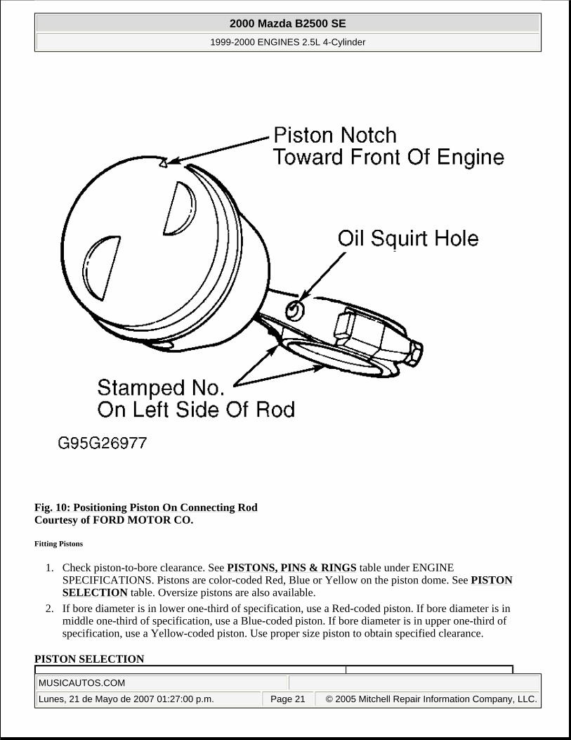
Fig. 10: Positioning Piston On Connecting Rod Courtesy of FORD MOTOR CO.
Fitting Pistons
1. Check piston-to-bore clearance. See PISTONS, PINS & RINGS table under ENGINE SPECIFICATIONS. Pistons are color-coded Red, Blue or Yellow on the piston dome. See PISTON SELECTION table. Oversize pistons are also available.
2. If bore diameter is in lower one-third of specification, use a Red-coded piston. If bore diameter is in middle one-third of specification, use a Blue-coded piston. If bore diameter is in upper one-third of specification, use a Yellow-coded piston. Use proper size piston to obtain specified clearance.
PISTON SELECTION
2000 Mazda B2500 SE
1999-2000 ENGINES 2.5L 4-Cylinder
MUSICAUTOS.COM
Lunes, 21 de Mayo de 2007 01:27:00 p.m. Page 21 © 2005 Mitchell Repair Information Company, LLC.

Piston Rings
1. Select proper ring set for bore diameter. Place NEW piston ring in cylinder bore in which it will be installed. Use inverted piston to square ring and push ring below normal ring wear area. Measure ring end gap. If ring end gap is too small, remove material from end of ring. If gap exceeds specification, try another ring set. See PISTONS, PINS & RINGS table under ENGINE SPECIFICATIONS.
2. Check side clearance of rings after installing on piston. Ensure clearance is within specification around entire circumference. Replace piston and/or rings if clearance is not within specification. See PISTONS, PINS & RINGS table. Ensure rings are properly spaced on piston before installing piston into cylinder. See Fig. 11 .
Cylinder Bore Diameter - In. (mm) Piston Color Code3.7795-3.7800 (96.000-96.012) Red3.7800-3.7805 (96.012-96.025) Blue3.7805-3.7810 (96.025-96.037) Yellow
2000 Mazda B2500 SE
1999-2000 ENGINES 2.5L 4-Cylinder
MUSICAUTOS.COM
Lunes, 21 de Mayo de 2007 01:27:00 p.m. Page 22 © 2005 Mitchell Repair Information Company, LLC.

Fig. 11: Positioning Rings On Piston Courtesy of FORD MOTOR CO.
Rod Bearings
1. Ensure oil squirt hole in connecting rod is properly positioned with arrow on top of piston. See Fig. 10 . Use Plastigage method to check rod bearing clearance.
2. If proper oil clearance cannot be obtained using standard bearings, try a combination of oversize bearings. 3. If use of bearing combinations do not bring clearance within specification, machine or replace crankshaft
as necessary. Always replace bearings in pairs. See CRANKSHAFT, MAIN & CONNECTING ROD
2000 Mazda B2500 SE
1999-2000 ENGINES 2.5L 4-Cylinder
MUSICAUTOS.COM
Lunes, 21 de Mayo de 2007 01:27:00 p.m. Page 23 © 2005 Mitchell Repair Information Company, LLC.

BEARINGS table under ENGINE SPECIFICATIONS.
Crankshaft & Main Bearings
1. When checking main bearing clearance in vehicle, position a jack under adjoining bearing counterweight being checked. Remove only one main bearing cap at a time.
2. Use Plastigage method to check main bearing clearance. If clearance is not within specification, replace bearings. If replacement of bearings do not bring clearance within specification, machine or replace crankshaft as necessary. See CRANKSHAFT, MAIN & CONNECTING ROD BEARINGS table under ENGINE SPECIFICATIONS.
3. Tighten main bearing cap bolts finger tight. Pry crankshaft forward and tighten bearing caps to specification. See TORQUE SPECIFICATIONS .
4. Check crankshaft end play. Replace thrust bearing or rear thrust plate if end play is not within specification. Thrust bearing is No. 3 (from front) main bearing. See CRANKSHAFT, MAIN & CONNECTING ROD BEARINGS table under ENGINE SPECIFICATIONS.
Cylinder Block
1. Using a feeler gauge and straightedge, check cylinder block head gasket surface for warpage. DO NOT machine more than .010" (.25 mm) from original gasket surface. Check cylinder bore for wear, taper, out-of-round and piston fit. Machine or replace as necessary. See CYLINDER BLOCK table under ENGINE SPECIFICATIONS.
2. Install all main bearing caps and tighten to specification before honing cylinder bore. See TORQUE SPECIFICATIONS . Use only a spring-loaded type cylinder hone. After honing, thoroughly clean bore with detergent and water solution. Rinse solution from bore thoroughly with clean water. Wipe bore clean with lint free cloth. Lubricate cylinder bores with engine oil.
ENGINE OILING
ENGINE LUBRICATION SYSTEM
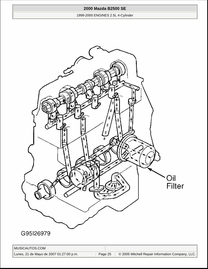
System is pressure fed from a rotor-type oil pump. Oil flows through oil filter before entering main oil galley. See Fig. 12 .
2000 Mazda B2500 SE
1999-2000 ENGINES 2.5L 4-Cylinder
MUSICAUTOS.COM
Lunes, 21 de Mayo de 2007 01:27:00 p.m. Page 24 © 2005 Mitchell Repair Information Company, LLC.
2000 Mazda B2500 SE
1999-2000 ENGINES 2.5L 4-Cylinder
MUSICAUTOS.COM
Lunes, 21 de Mayo de 2007 01:27:00 p.m. Page 25 © 2005 Mitchell Repair Information Company, LLC.

Fig. 12: Cross-Sectional View Of Engine Oiling SystemCourtesy of FORD MOTOR CO.
Crankcase Capacity
Crankcase capacity is 4 qts. (3.79L) without oil filter and 5 qts. (4.74L) with oil filter.
Oil Pressure
Normal oil pressure at 2000 RPM should be 40-60 psi (2.8-4.2 kg/cm2 ) with engine at normal operating temperature.
Oil Pressure Relief Valve
Oil pressure relief valve is located in oil pump body. Valve is not adjustable.
OIL PUMP
Removal
Remove timing belt. See TIMING BELT under REMOVAL & INSTALLATION. Remove oil pump sprocket. Disconnect camshaft position sensor wiring connector. Remove camshaft position sensor from oil pump. Remove oil pump retaining bolts. Remove oil pump assembly.
Installation
To install, reverse removal procedure using NEW oil pump gasket. Prime oil pump assembly before installation. Tighten bolts and nuts to specification. See TORQUE SPECIFICATIONS .
TORQUE SPECIFICATIONS
TORQUE SPECIFICATIONS
NOTE: Manufacturer does not supply overhaul procedures for oil pump.
Application Ft. Lbs. (N.m)A/C Compressor Bracket-to-Engine Bolts 35 (45)A/C Compressor Mounting Bolts 15-21 (21-28)Accelerator Cable Bracket Bolts 15-21 (21-28)Camshaft Sprocket Bolt 52-70 (70-95)Connecting Rod Cap Nuts
Step 1 25-30 (34-41)Step 2 30-36 (41-49)
Converter-To-Exhaust Manifold Flange Bolts 25-34 (34-46)Cooling Fan Bolts 10-13 (13-17)Crankshaft Pulley Bolt 92-122 (125-165)
2000 Mazda B2500 SE
1999-2000 ENGINES 2.5L 4-Cylinder
MUSICAUTOS.COM
Lunes, 21 de Mayo de 2007 01:27:00 p.m. Page 26 © 2005 Mitchell Repair Information Company, LLC.

Cylinder Head Bolts (1)
Step 1 52 (70)Step 2 (Loosen & Retighten) 52 (70)Step 3 Additional 90-100 Degrees
EGR Tube Nuts 25-35 (34-47)Engine Mount Nuts 63-85 (85-115)Engine Mount-To-Bracket Bolts 63-85 (88-115)Engine-To-Transmission Bolts 30-41 (40-55)Exhaust Manifold Bolts (2)
Step 1 15-17 (20-23)Step 2 44-59 (60-80)
Flexplate-To-Torque Converter Bolts 22-30 (30-40)Flywheel-To-Crankshaft Bolts 54-64 (73-87)Generator Bracket Bolts 30-40 (40-55)Generator Mounting Bolts 30-40 (41-54)Lower Intake Manifold Bolts/Nut (3)
Step 1 (4)
Step 2 19-28 (26-38)Main Bearing Cap Bolts
Step 1 50-60 (68-81)Step 2 75-85 (102-115)
Oil Pump Pick-Up Tube Nuts 15-22 (20-30)Oil Pump Sprocket Bolt 30-40 (40-55)Rear Mount-To-Crossmember Nuts 64-81 (87-110)Rear Mount-To-Transmission Bolts 64-81 (87-110)Starter Motor Bolts 15-20 (20-27)Timing Belt Tensioner Adjusting Bolt 26-33 (35-45)Timing Belt Tensioner Pivot Bolt 30-41 (40-55)Transmission Oil Cooler Lines 18-23 (24-31)Upper Intake Manifold Bolts (3)
Step 1 (4)
Step 2 19-28 (26-38)Water Pump Bolts (5) 15-22 (20-30)Water Pump Inlet Tube Bolts 7-9 (9-12)
INCH Lbs. (N.m)Camshaft Position Sensor Bolts 44-62 (5-7)Camshaft Thrust Plate Bolts 71-106 (8-12)Crankshaft Position Sensor Bolt 71-106 (8-12)Engine Timing Belt Cover Bolt 71-106 (8-12)
2000 Mazda B2500 SE
1999-2000 ENGINES 2.5L 4-Cylinder
MUSICAUTOS.COM
Lunes, 21 de Mayo de 2007 01:27:00 p.m. Page 27 © 2005 Mitchell Repair Information Company, LLC.

ENGINE SPECIFICATIONS
GENERAL SPECIFICATIONS
CRANKSHAFT, MAIN & CONNECTING ROD BEARINGS
Oil Pan-To-Block Bolts 124-142 (14-16)Oil Pump-To-Block Bolts 88-124 (10-14)Spark Plugs 80-177 (9-20)Valve Cover Bolts 80-115 (9-13)(1) Tighten NEW bolts in proper sequence. See Fig. 4 .(2) Tighten in proper sequence. See Fig. 3 .(3) Tighten in proper sequence. See Fig. 2 .(4) Tighten bolts to 62-88 INCH lbs. (7-10 N.m)(5) Apply sealant to bolt threads.
Application SpecificationDisplacement 153 Cu. In. (2.5L)Bore 3.78" (96.0 mm)Stroke 3.402" (86.41 mm)Compression Ratio 9.4:1Fuel System SFI
Application In. (mm)Crankshaft
End PlayDesired .004-.008 (.10-.20)Allowable .012 (.30)
RunoutDesired Maximum .002 (.050)Service Limit .005 (.127)
Main BearingsJournal Diameter 2.2051-2.2059 (56.009-56.030)Journal Out-Of-Round .0006 (.015)Journal Taper (1) .0006 (.015)Oil Clearance
Desired .0008-.0015 (.020-.038)Allowable .0008-.0026 (.020-.066)
Connecting Rod BearingsJournal Diameter 2.0464-2.0472 (51.979-51.998)Journal Out-Of-Round .0006 (.015)
2000 Mazda B2500 SE
1999-2000 ENGINES 2.5L 4-Cylinder
MUSICAUTOS.COM
Lunes, 21 de Mayo de 2007 01:27:01 p.m. Page 28 © 2005 Mitchell Repair Information Company, LLC.

CONNECTING RODS
PISTONS, PINS & RINGS
Journal Taper (1) .0006 (.015)Oil Clearance
Desired .0008-.0015 (.020-.038)Allowable .0008-.0026 (.020-.066)
(1) Specification listed is per 1" (25.4 mm).
Application In. (mm)Connecting Rod Pin Bore Diameter .9096-.9112 (23.103-23.144)Center-To-Center Length 5.4558-5.4591 (138.577-138.661)Maximum Bend .0015 (.038)Maximum Twist .003 (.08)Side Play
Standard .0035-.0115 (.089-.292)Service Limit .014 (.36)
Application In. (mm)Pistons
Clearance .001-.002 (.03-.05)Diameter (1)
Red 3.7780-3.7885 (95.961-95.974)Blue 3.7785-3.7790 (95.974-95.987)Yellow 3.7790-3.7795 (95.987-95.999)
PinsDiameter (2) .9121-.9122 (23.167-23.170)Piston Fit .0004-.0007 (.001-.017)Rod Fit Interference Fit
RingsNo. 1 End Gap .008-.014 (.20-.35)No. 2 End Gap .013-.019 (.32-.47)
Side Clearance .0014-.0030 (.035-.076)No. 3 (Oil)
End Gap (Steel Rail) .010-.030 (.25-.80)Side Clearance Snug Fit
(1) Piston diameter is measured at 1.00" (25.4 mm) from oil ring groove, at 90-degrees to piston pin. To select correct pistons, see CYLINDER BLOCK ASSEMBLY under OVERHAUL.
(2) Standard diameter listed. Available in .001" (.02 mm) and .002" (.05 mm) oversize.
2000 Mazda B2500 SE
1999-2000 ENGINES 2.5L 4-Cylinder
MUSICAUTOS.COM
Lunes, 21 de Mayo de 2007 01:27:01 p.m. Page 29 © 2005 Mitchell Repair Information Company, LLC.

CYLINDER BLOCK
VALVES & VALVE SPRINGS
CYLINDER HEAD
Application In. (mm)Cylinder Bore
Standard Diameter 3.7795-3.7810 (95.999-96.015)Maximum Out-Of-Round .0015 (.038)Maximum Taper .010 (.25)
Maximum Deck Warpage (1) .003 (.08)(1) Specification listed is per 6" (152 mm). Maximum of .006" (.15 mm) overall. DO NOT machine
more than .010" (.25 mm) from original gasket surface.
Application SpecificationIntake Valves
Face Angle 45°Head Diameter 1.730-1.740" (43.9-44.2 mm)Stem Diameter .2746-.2754" (6.975-6.995 mm)
Exhaust ValvesFace Angle 45°Head Diameter 1.49-1.51" (37.8-38.5 mm)Stem Diameter .2736-.2744" (6.949-6.970 mm)
Valve Margin .031" (.79 mm)Valve Springs
Free Length (Approx.) 2.02" (51.31 mm)Installed Height 1.54-1.58" (39.1-40.1 mm)Out-Of-Square .078" (1.98 mm)
Lbs. @ In. (kg @ mm)Pressure
Valve Closed 57-63 @ 1.56 (26-29 @ 39.6)Valve Open 118-132 @ 1.16 (54-60 @ 29.5)
Application SpecificationMaximum Warpage (1) .003" (.08 mm)Valve Seats
Intake ValveSeat Angle 45°Seat Width .068-.088" (1.73-2.24 mm)Maximum Seat Runout .0016" (.040 mm)
Exhaust ValveSeat Angle 45°
2000 Mazda B2500 SE
1999-2000 ENGINES 2.5L 4-Cylinder
MUSICAUTOS.COM
Lunes, 21 de Mayo de 2007 01:27:01 p.m. Page 30 © 2005 Mitchell Repair Information Company, LLC.

CAMSHAFT
VALVE LASH ADJUSTERS
Seat Width .070-.090" (1.78-2.29 mm)Maximum Seat Runout .0016" (.040 mm)
Valve GuidesIntake Valve
Bore Diameter .3433-.3443" (8.720-8.745 mm)Valve Stem-To-Guide
Oil ClearanceStandard .0008-.0027" (.020-.069 mm)Service Limit .004" (.10 mm)
Exhaust ValveBore Diameter .3433-.3443" (8.720-8.745 mm)Valve Stem-To-Guide
Oil ClearanceStandard .0018-.0037" (.045-.094 mm)Service Limit .004" (.10 mm)
(1) Specification listed is taken within a 6" (152 mm) area. Overall warpage is .006" (.15 mm). DO NOT machine more than .010" (.25 mm) from original gasket surface.
Application In. (mm)Camshaft
End PlayStandard .001-.007 (.03-.18)Service Limit .009 (.23)
Journal Diameter 1.7713-1.7720 (44.991-45.009)Lobe Lift .2163 (5.494)Oil Clearance
Standard .001-.003 (.03-.08)Service Limit .01 (.25)
Application In. (mm)Adjuster Diameter .8422-.8427 (21.392-21.405)Bore Diameter .8430-.8449 (21.412-21.460)Collapsed Lash Adjuster Clearance
Desired .040-.050 (1.02-1.27)Allowable .035-.055 (.89-1.40)
Oil Clearance .0007-.0027 (.018-.069)
2000 Mazda B2500 SE
1999-2000 ENGINES 2.5L 4-Cylinder
MUSICAUTOS.COM
Lunes, 21 de Mayo de 2007 01:27:01 p.m. Page 31 © 2005 Mitchell Repair Information Company, LLC.