product knowledge template - freeyvonet.florent.free.fr/serveur/cours catia/catia product...catia v5...
TRANSCRIPT

Instructor Notes:
Product Knowledge Template
Copyright DASSAULT SYSTEMES 1
��������������
Cop
yrig
ht D
AS
SA
ULT
SYS
TEM
ES
Product Knowledge Template
CATIA V5 TrainingFoils
Version 5 Release 19January 2009
EDU_CAT_EN_PKT_FI_V5R19
Instructor Notes:
Product Knowledge Template
Copyright DASSAULT SYSTEMES 2
��������������
Cop
yrig
ht D
AS
SA
ULT
SYS
TEM
ES
About this courseObjectives of the courseUpon completion of this course you will be able to: - Create and reuse Power Copies and User Defined Features. - Create and reuse advanced instantiation features like Knowledge Pattern. - Create Part and Assembly Templates and reuse them in a new context.
Targeted audienceCATIA V5 users
PrerequisitesStudents attending this course should have knowlegde of CATIA V5 Fundamentals and Knowledgeware Basics.
8 hours
Instructor Notes:
Product Knowledge Template
Copyright DASSAULT SYSTEMES 3
��������������
Cop
yrig
ht D
AS
SA
ULT
SYS
TEM
ES
Table of Contents (1/3)
Product Knowledge Template Workbench Presentation 6What are Templates? 7Examples of Templates 9Accessing the Workbench 10User Interface 11User Settings 12
Creating and Using PowerCopies 16PowerCopy Presentation 17Creating a PowerCopy 22Saving a PowerCopy 29Instantiating a PowerCopy 32KeyWay Recap Exercise 37To Sum Up 38
Creating and Using User Defined Features 39User Defined Features: Presentation 40Creating a User Defined Feature 47Saving a User Defined Feature 58Instantiating a User Defined Feature 60
Instructor Notes:
Product Knowledge Template
Copyright DASSAULT SYSTEMES 4
��������������
Cop
yrig
ht D
AS
SA
ULT
SYS
TEM
ES
Table of Contents (2/3)
UDF Meta Inputs 70User Defined Features Recap Exercises 76
Creating and Using Part and Assembly Templates 79Presentation of Document Templates 80Creating a Document Template 85Saving a Document Template 91Instantiating a Document Template 94Document Templates Recap Exercises 99
Managing Standard Components 103Introduction 104Methodology Overview 105Knowledge Environment Settings 106About ARM Catalogs 107Creating an ARM Catalog 108Choosing the right standard component 111
Creating and Using Knowledge Pattern 116Where do we use ‘Knowledge Pattern’ ? 117Example of Knowledge Pattern 118
Instructor Notes:
Product Knowledge Template
Copyright DASSAULT SYSTEMES 5
��������������
Cop
yrig
ht D
AS
SA
ULT
SYS
TEM
ES
Table of Contents (3/3)
The Mechanism of Knowledge Pattern 119General Process - Knowledge Pattern – UDF Instantiation 121General Process - Knowledge Pattern – Datum Creation 122Knowledge Pattern – Script Explanations 131Additional Information – Knowledge Pattern 136Summary 139
Instructor Notes:
Product Knowledge Template
Copyright DASSAULT SYSTEMES 6
��������������
Cop
yrig
ht D
AS
SA
ULT
SYS
TEM
ES
PKT Workbench PresentationYou will learn the concept of templates and about the user interface and specific settings of the Product Knowledge Template Workbench.
Instructor Notes:
Product Knowledge Template
Copyright DASSAULT SYSTEMES 7
��������������
Cop
yrig
ht D
AS
SA
ULT
SYS
TEM
ES
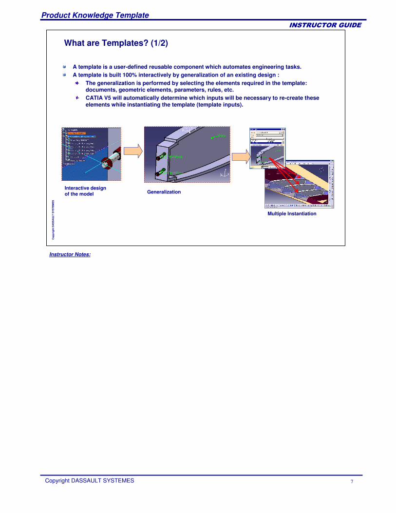
What are Templates? (1/2)
A template is a user-defined reusable component which automates engineering tasks.A template is built 100% interactively by generalization of an existing design :
The generalization is performed by selecting the elements required in the template: documents, geometric elements, parameters, rules, etc.CATIA V5 will automatically determine which inputs will be necessary to re-create these elements while instantiating the template (template inputs).
Generalization
Multiple Instantiation
Interactive design of the model
Instructor Notes:
Product Knowledge Template
Copyright DASSAULT SYSTEMES 8
��������������
Cop
yrig
ht D
AS
SA
ULT
SYS
TEM
ES
What are Templates? (2/2)
Users can create three types of templates:User Feature/PowerCopy: A collection of CATIA features, including knowledge features, that can be reused in a part’s design. � Allows customers to manipulate their own semantic objects in place of V5
standard objects.� Once instantiated, users get a black box (in case of UDF) behaving like any
other feature with published parameters that can be edited.
Part Template: A part and its associated documents (drawing, analysis, process) can be reused inside products.� Once instantiated, the part is duplicated and you get an independent
component which is adapted to the new context.
Assembly Template: A whole assembly and its associated documents can be reused inside products.� Once instantiated, the assembly is duplicated and the embedded parts can be
independent or as a reference to the original one.
Instructor Notes:
Product Knowledge Template
Copyright DASSAULT SYSTEMES 9
��������������
Cop
yrig
ht D
AS
SA
ULT
SYS
TEM
ES
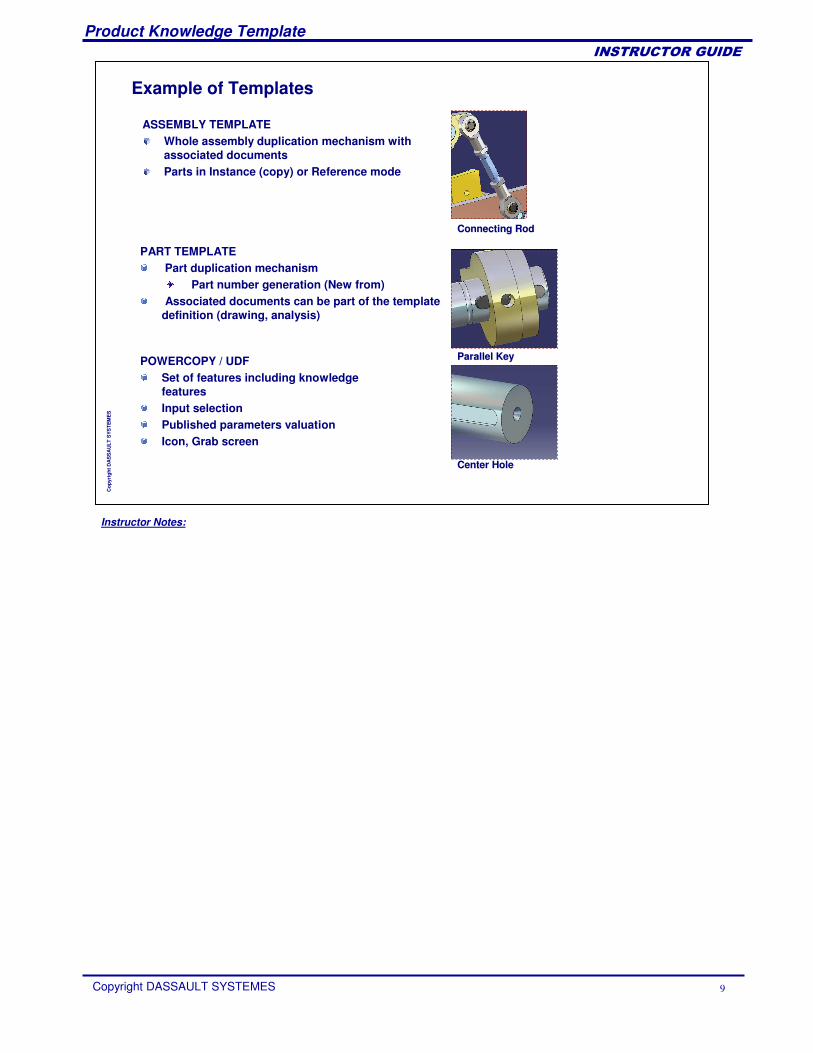
PART TEMPLATEPart duplication mechanism
Part number generation (New from)Associated documents can be part of the template
definition (drawing, analysis)
Parallel KeyParallel KeyPOWERCOPY / UDFSet of features including knowledge featuresInput selectionPublished parameters valuationIcon, Grab screen
Center HoleCenter Hole
Example of Templates
ASSEMBLY TEMPLATEWhole assembly duplication mechanism with associated documentsParts in Instance (copy) or Reference mode
Connecting RodConnecting Rod
Instructor Notes:
Product Knowledge Template
Copyright DASSAULT SYSTEMES 10
��������������
Cop
yrig
ht D
AS
SA
ULT
SYS
TEM
ES
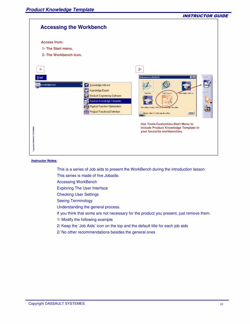
Accessing the Workbench
Access from:
1- The Start menu.
2- The Workbench Icon.
1- 2-
Use Tools/Customize+Start Menu to include Product Knowledge Template in your favourite workbenches.
This is a series of Job aids to present the WorkBench during the introduction lesson.
This series is made of five Jobaids:
Accessing WorkBench
Exploring The User Interface
Checking User Settings
Seeing Terminology
Understanding the general process.
If you think that some are not necessary for the product you present, just remove them.
1/ Modify the following example
2/ Keep the ‘Job Aids’ icon on the top and the default title for each job aids
2/ No other recommendations besides the general ones
Instructor Notes:
Product Knowledge Template
Copyright DASSAULT SYSTEMES 11
��������������
Cop
yrig
ht D
AS
SA
ULT
SYS
TEM
ES
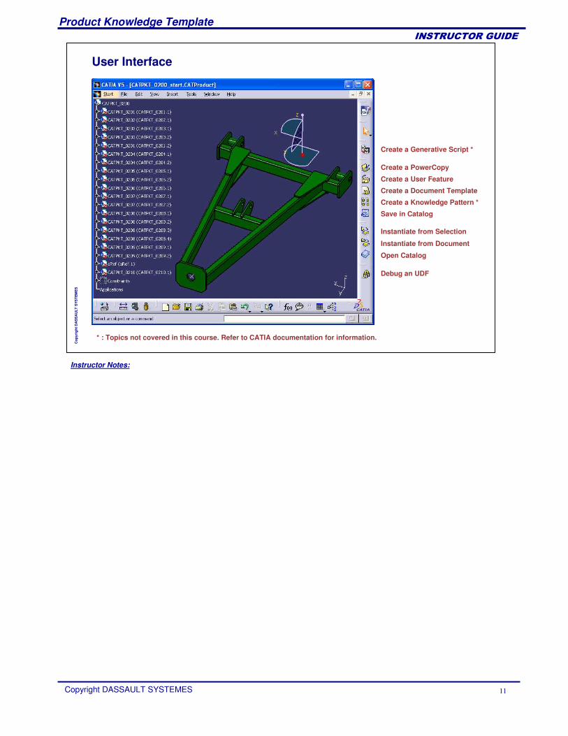
User Interface
Create a Generative Script *
Create a PowerCopy
Save in Catalog
Instantiate from Selection
Create a Document Template
Create a User Feature
Open Catalog
Instantiate from Document
Create a Knowledge Pattern *
Debug an UDF
* : Topics not covered in this course. Refer to CATIA documentation for information.
Instructor Notes:
Product Knowledge Template
Copyright DASSAULT SYSTEMES 12
��������������
Cop
yrig
ht D
AS
SA
ULT
SYS
TEM
ES
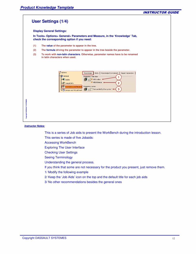
User Settings (1/4)
Display General Settings:
In Tools> Options> General> Parameters and Measure, in the ‘Knowledge’ Tab, check the corresponding option if you need:
(1) The value of the parameter to appear in the tree.
(2) The formula driving the parameter to appear in the tree beside the parameter.
(3) To work with non-latin characters. Otherwise, parameter names have to be renamed in latin characters when used.
1
2
3
This is a series of Job aids to present the WorkBench during the introduction lesson.
This series is made of five Jobaids:
Accessing WorkBench
Exploring The User Interface
Checking User Settings
Seeing Terminology
Understanding the general process.
If you think that some are not necessary for the product you present, just remove them.
1/ Modify the following example
2/ Keep the ‘Job Aids’ icon on the top and the default title for each job aids
3/ No other recommendations besides the general ones
Instructor Notes:
Product Knowledge Template
Copyright DASSAULT SYSTEMES 13
��������������
Cop
yrig
ht D
AS
SA
ULT
SYS
TEM
ES
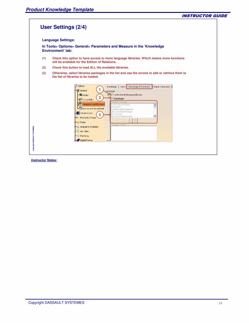
User Settings (2/4)
(1) Check this option to have access to more language libraries. Which means more functions will be available for the Edition of Relations.
(2) Check this button to load ALL the available libraries.
(3) Otherwise, select libraries packages in the list and use the arrows to add or retrieve them to the list of libraries to be loaded.
2
1
3
Language Settings:
In Tools> Options> General> Parameters and Measure in the ‘Knowledge Environment’ tab:
Instructor Notes:
Product Knowledge Template
Copyright DASSAULT SYSTEMES 14
��������������
Cop
yrig
ht D
AS
SA
ULT
SYS
TEM
ES
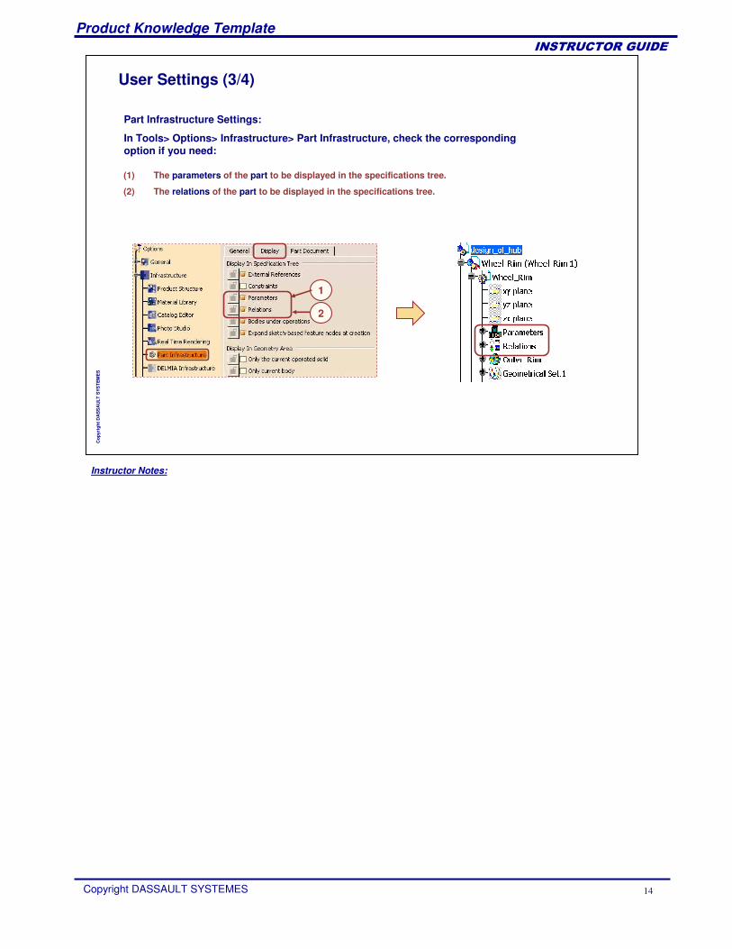
User Settings (3/4)
(1) The parameters of the part to be displayed in the specifications tree.
(2) The relations of the part to be displayed in the specifications tree.
1
2
Part Infrastructure Settings:
In Tools> Options> Infrastructure> Part Infrastructure, check the corresponding option if you need:
Instructor Notes:
Product Knowledge Template
Copyright DASSAULT SYSTEMES 15
��������������
Cop
yrig
ht D
AS
SA
ULT
SYS
TEM
ES
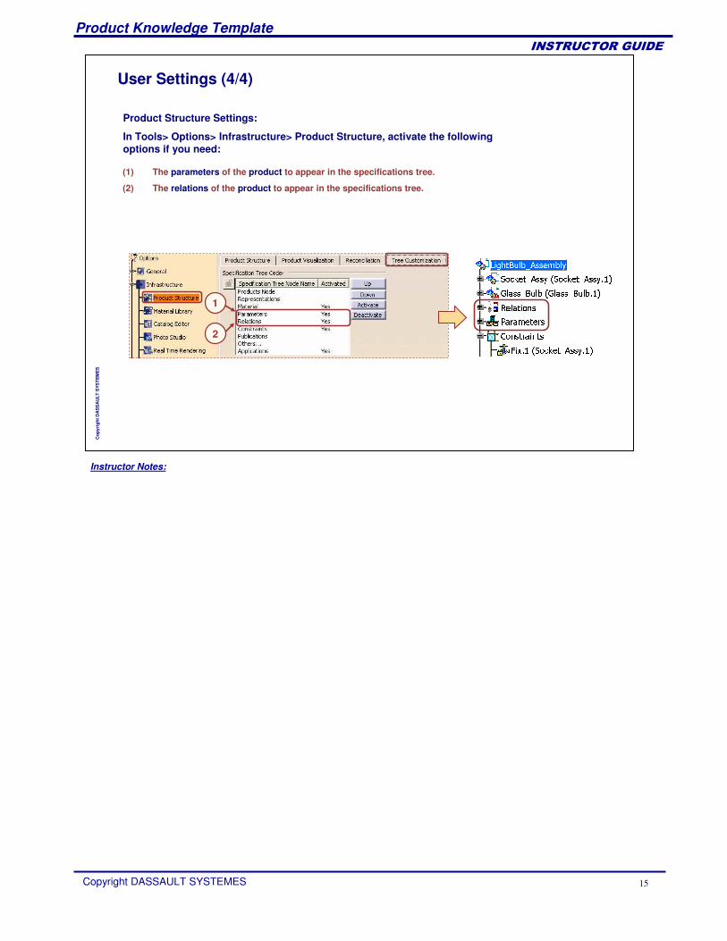
User Settings (4/4)
(1) The parameters of the product to appear in the specifications tree.
(2) The relations of the product to appear in the specifications tree.
2
1
Product Structure Settings:
In Tools> Options> Infrastructure> Product Structure, activate the following options if you need:
Instructor Notes:
Product Knowledge Template
Copyright DASSAULT SYSTEMES 16
��������������
Cop
yrig
ht D
AS
SA
ULT
SYS
TEM
ES
Creating and Using PowerCopies
PowerCopy PresentationCreating a PowerCopySaving a PowerCopyInstantiating a PowerCopyKeyWay Recap ExerciseTo Sum Up
Instructor Notes:
Product Knowledge Template
Copyright DASSAULT SYSTEMES 17
��������������
Cop
yrig
ht D
AS
SA
ULT
SYS
TEM
ES
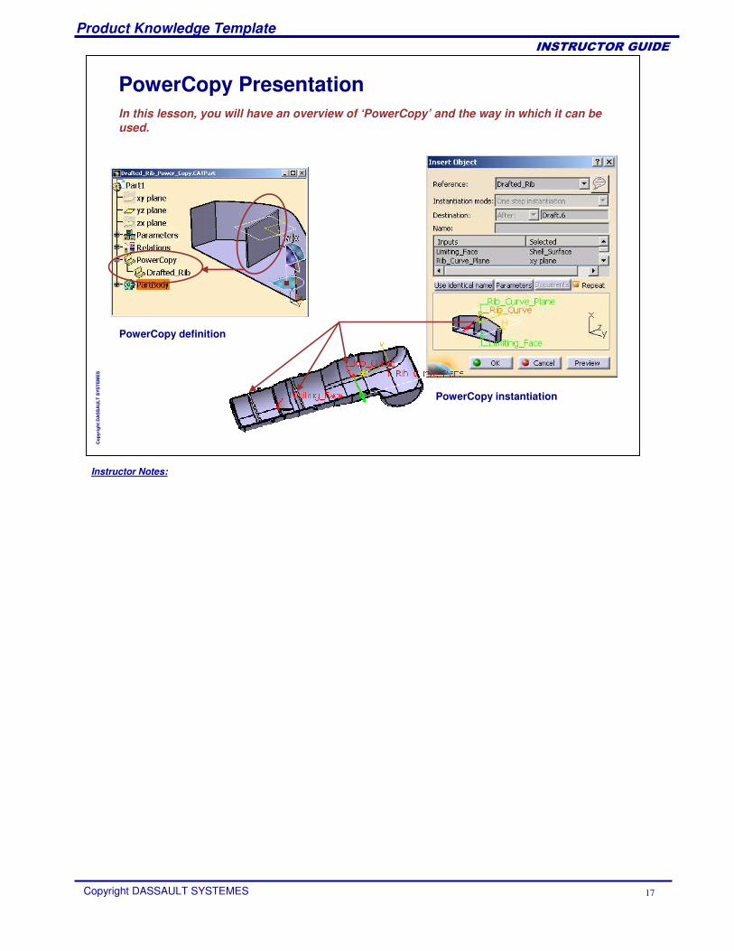
PowerCopy PresentationIn this lesson, you will have an overview of ‘PowerCopy’ and the way in which it can be used.
PowerCopy definition
PowerCopy instantiation
Instructor Notes:
Product Knowledge Template
Copyright DASSAULT SYSTEMES 18
��������������
Cop
yrig
ht D
AS
SA
ULT
SYS
TEM
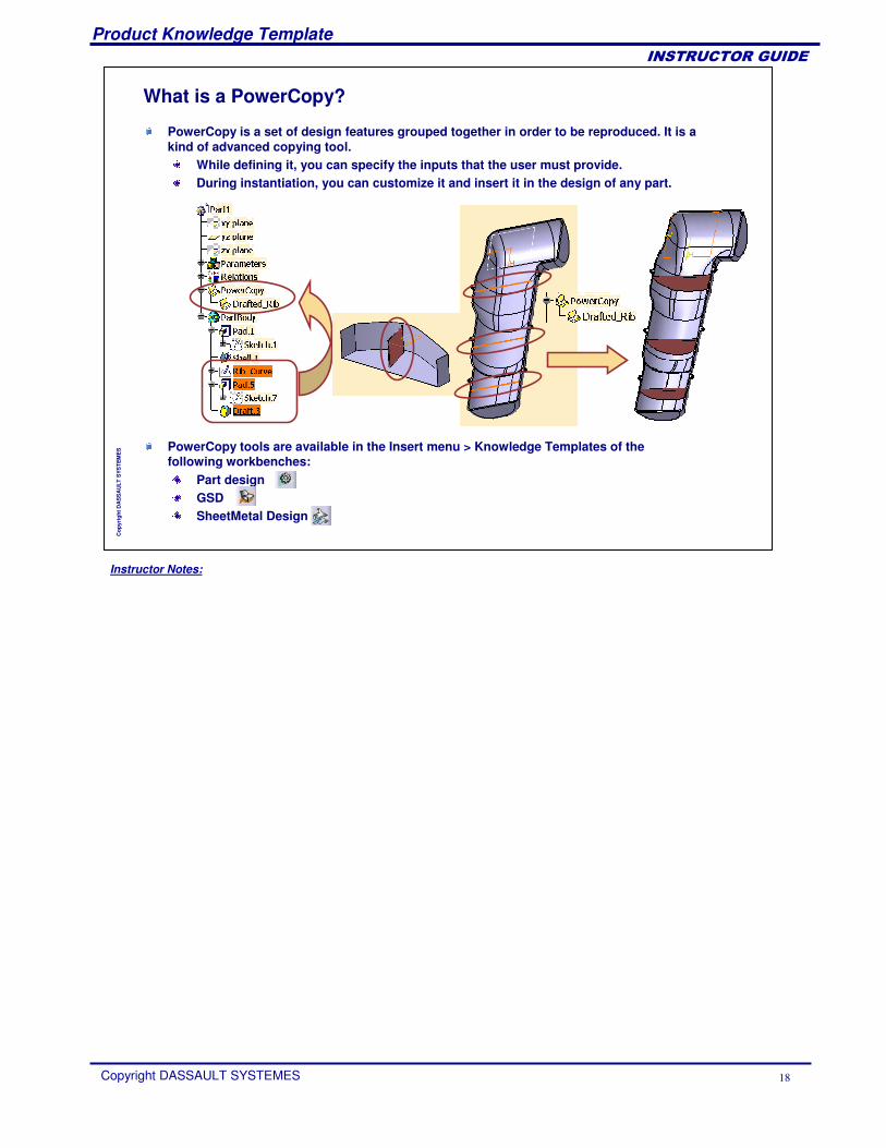
ES PowerCopy tools are available in the Insert menu > Knowledge Templates of the
following workbenches:Part designGSDSheetMetal Design
What is a PowerCopy?
PowerCopy is a set of design features grouped together in order to be reproduced. It is a kind of advanced copying tool.
While defining it, you can specify the inputs that the user must provide.During instantiation, you can customize it and insert it in the design of any part.
Instructor Notes:
Product Knowledge Template
Copyright DASSAULT SYSTEMES 19
��������������
Cop
yrig
ht D
AS
SA
ULT
SYS
TEM
ES
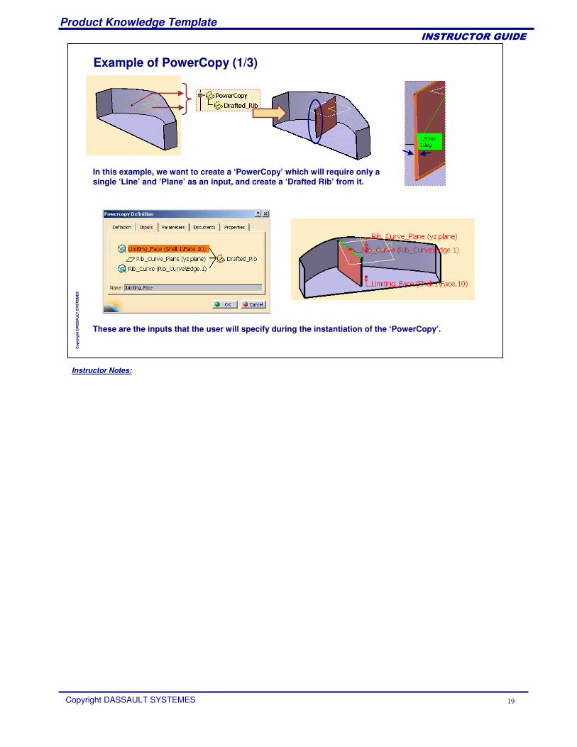
Example of PowerCopy (1/3)
In this example, we want to create a ‘PowerCopy’ which will require only a single ‘Line’ and ‘Plane’ as an input, and create a ‘Drafted Rib’ from it.
These are the inputs that the user will specify during the instantiation of the ‘PowerCopy’.
Instructor Notes:
Product Knowledge Template
Copyright DASSAULT SYSTEMES 20
��������������
Cop
yrig
ht D
AS
SA
ULT
SYS
TEM
ES
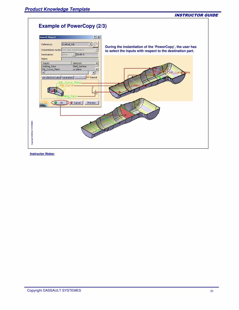
Example of PowerCopy (2/3)
During the instantiation of the ‘PowerCopy’, the user has to select the inputs with respect to the destination part.
Instructor Notes:
Product Knowledge Template
Copyright DASSAULT SYSTEMES 21
��������������
Cop
yrig
ht D
AS
SA
ULT
SYS
TEM
ES
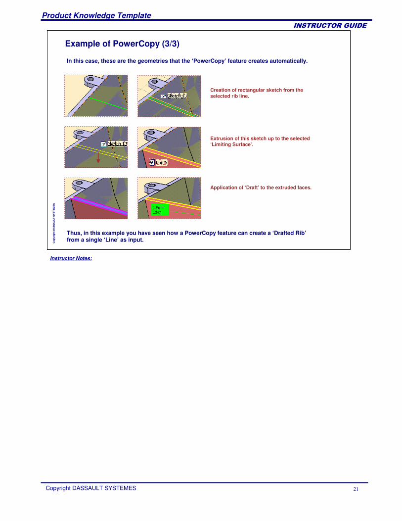
Example of PowerCopy (3/3)
In this case, these are the geometries that the ‘PowerCopy’ feature creates automatically.
Creation of rectangular sketch from the selected rib line.
Extrusion of this sketch up to the selected ‘Limiting Surface’.
Application of ‘Draft’ to the extruded faces.
Thus, in this example you have seen how a PowerCopy feature can create a ‘Drafted Rib’from a single ‘Line’ as input.
Instructor Notes:
Product Knowledge Template
Copyright DASSAULT SYSTEMES 22
��������������
Cop
yrig
ht D
AS
SA
ULT
SYS
TEM
ES
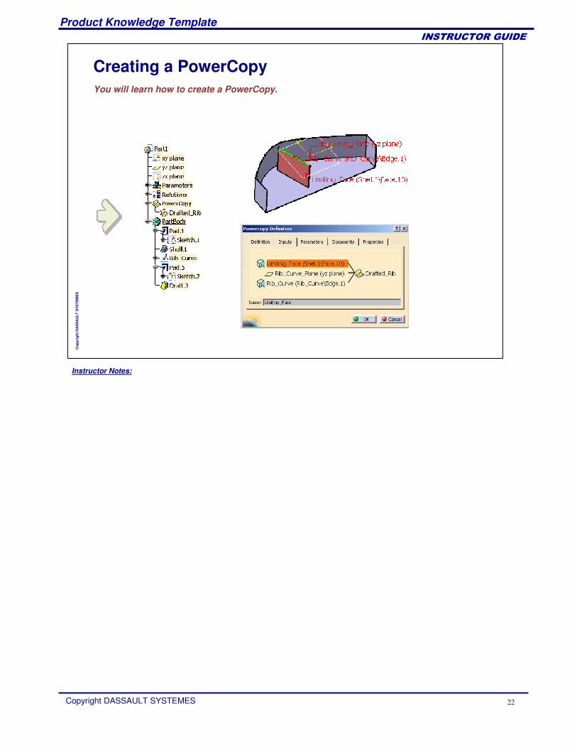
Creating a PowerCopyYou will learn how to create a PowerCopy.
Instructor Notes:
Product Knowledge Template
Copyright DASSAULT SYSTEMES 23
��������������
Cop
yrig
ht D
AS
SA
ULT
SYS
TEM
ES
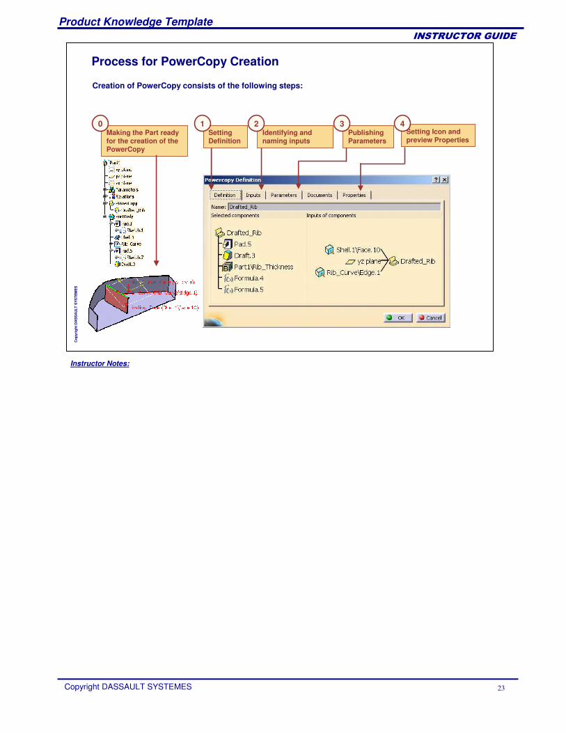
Setting Icon and preview Properties
Publishing Parameters
Identifying and naming inputs
Setting Definition
Making the Part ready for the creation of the PowerCopy
Creation of PowerCopy consists of the following steps:
Process for PowerCopy Creation
0 1 432
Instructor Notes:
Product Knowledge Template
Copyright DASSAULT SYSTEMES 24
��������������
Cop
yrig
ht D
AS
SA
ULT
SYS
TEM
ES
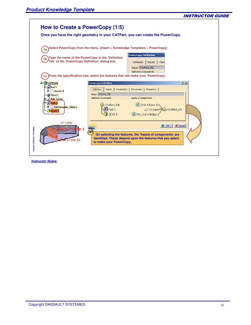
1a
Once you have the right geometry in your CATPart, you can create the PowerCopy.
How to Create a PowerCopy (1/5)
Select PowerCopy from the menu. (Insert > Knowledge Templates > PowerCopy)
1b Type the name of the PowerCopy in the ‘Definition Tab’ of the ‘PowerCopy Definition’ dialog box.
1c From the specification tree, select the features that will make your ‘PowerCopy’.
On selecting the features, the ‘Inputs of components’ are identified. These depend upon the features that you select to make your PowerCopy.
Instructor Notes:
Product Knowledge Template
Copyright DASSAULT SYSTEMES 25
��������������
Cop
yrig
ht D
AS
SA
ULT
SYS
TEM
ES
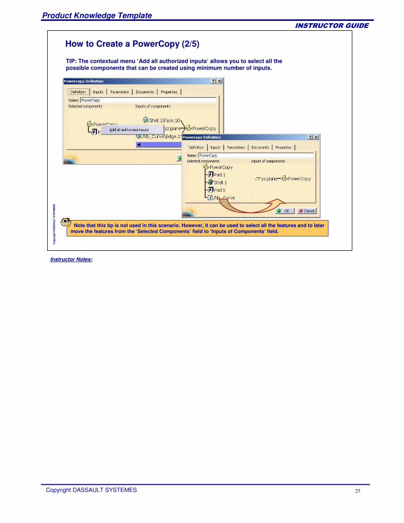
How to Create a PowerCopy (2/5)
Note that this tip is not used in this scenario. However, it can be used to select all the features and to later move the features from the ‘Selected Components’ field to ‘Inputs of Components’ field.
TIP: The contextual menu ‘Add all authorized inputs’ allows you to select all the possible components that can be created using minimum number of inputs.
Instructor Notes:
Product Knowledge Template
Copyright DASSAULT SYSTEMES 26
��������������
Cop
yrig
ht D
AS
SA
ULT
SYS
TEM
ES
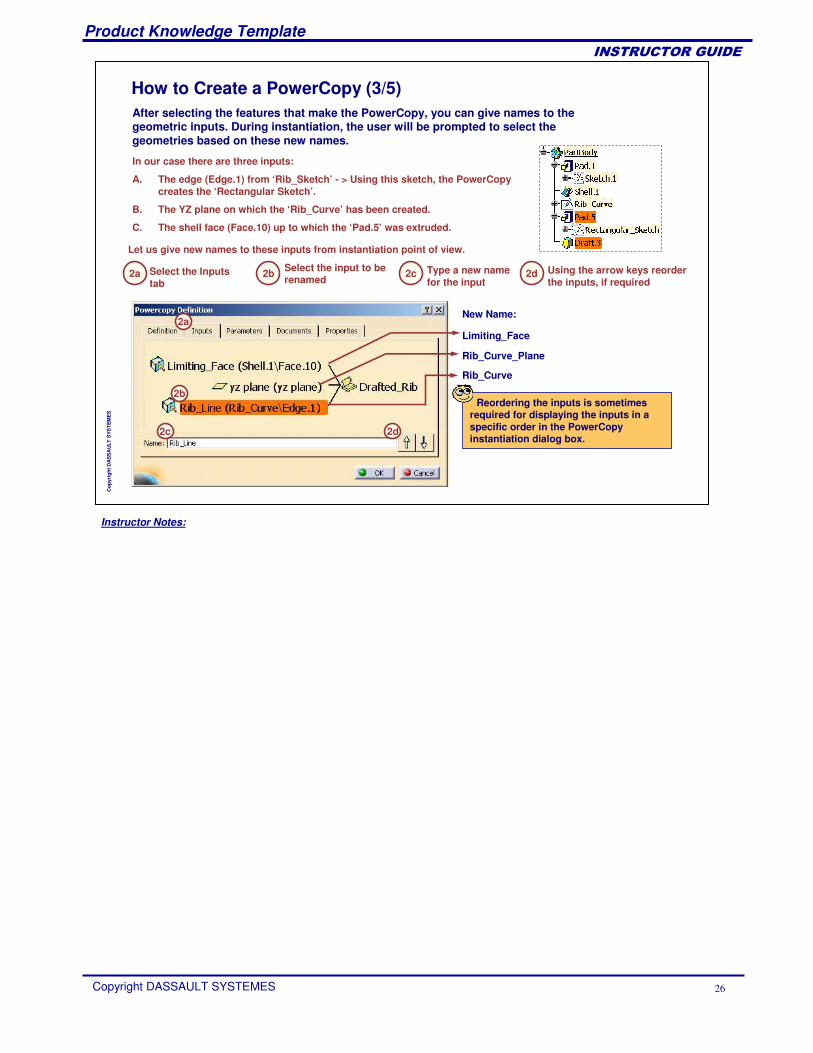
2a
After selecting the features that make the PowerCopy, you can give names to the geometric inputs. During instantiation, the user will be prompted to select the geometries based on these new names.
In our case there are three inputs:
A. The edge (Edge.1) from ‘Rib_Sketch’ - > Using this sketch, the PowerCopy creates the ‘Rectangular Sketch’.
B. The YZ plane on which the ‘Rib_Curve’ has been created.
C. The shell face (Face.10) up to which the ‘Pad.5’ was extruded.
2c Type a new name for the input
Select the Inputs tab
2b Select the input to be renamed
Let us give new names to these inputs from instantiation point of view.
2b
2c
2a
New Name:
Limiting_Face
Rib_Curve_Plane
Rib_Curve
2d
2d Using the arrow keys reorder the inputs, if required
Reordering the inputs is sometimes required for displaying the inputs in a specific order in the PowerCopy instantiation dialog box.
How to Create a PowerCopy (3/5)
Instructor Notes:
Product Knowledge Template
Copyright DASSAULT SYSTEMES 27
��������������
Cop
yrig
ht D
AS
SA
ULT
SYS
TEM
ES
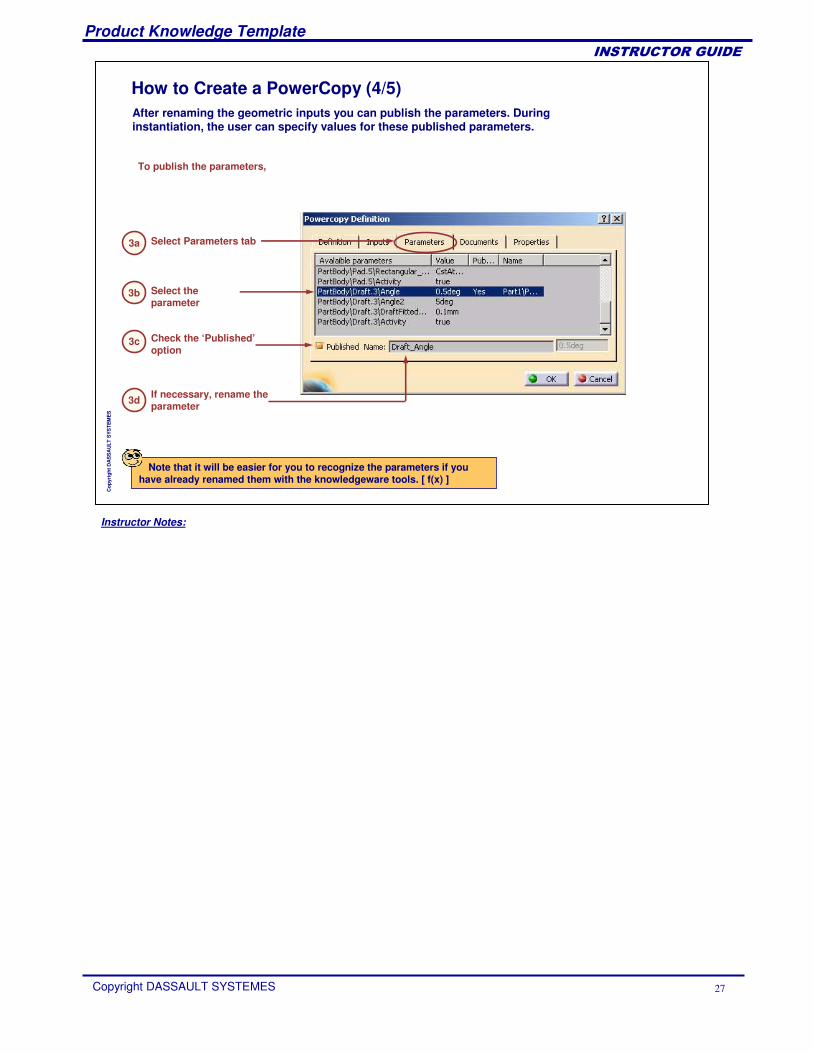
After renaming the geometric inputs you can publish the parameters. During instantiation, the user can specify values for these published parameters.
How to Create a PowerCopy (4/5)
3a Select Parameters tab
To publish the parameters,
3b Select the parameter
3c Check the ‘Published’option
3d If necessary, rename the parameter
Note that it will be easier for you to recognize the parameters if you have already renamed them with the knowledgeware tools. [ f(x) ]
Instructor Notes:
Product Knowledge Template
Copyright DASSAULT SYSTEMES 28
��������������
Cop
yrig
ht D
AS
SA
ULT
SYS
TEM
ES
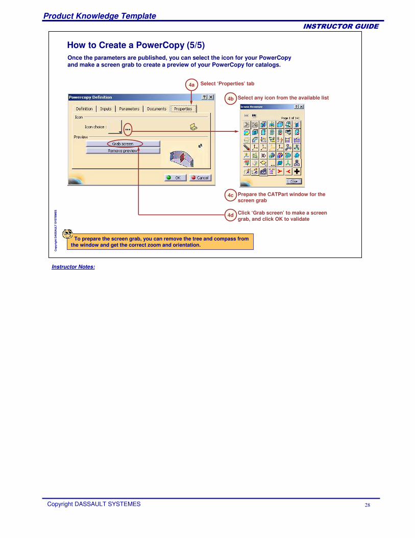
Once the parameters are published, you can select the icon for your PowerCopy and make a screen grab to create a preview of your PowerCopy for catalogs.
How to Create a PowerCopy (5/5)
4a Select ‘Properties’ tab
4b Select any icon from the available list
4c Prepare the CATPart window for the screen grab
Click ‘Grab screen’ to make a screen grab, and click OK to validate
4d
To prepare the screen grab, you can remove the tree and compass from the window and get the correct zoom and orientation.
Instructor Notes:
Product Knowledge Template
Copyright DASSAULT SYSTEMES 29
��������������
Cop
yrig
ht D
AS
SA
ULT
SYS
TEM
ES
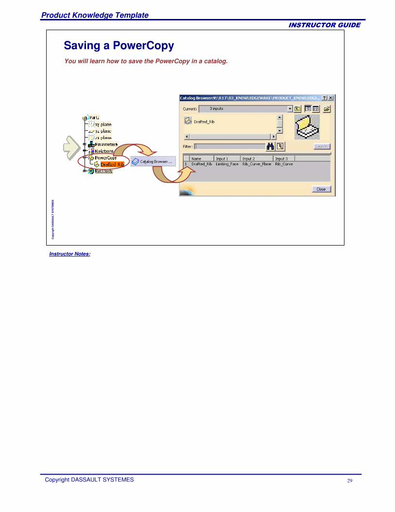
Saving a PowerCopyYou will learn how to save the PowerCopy in a catalog.
Instructor Notes:
Product Knowledge Template
Copyright DASSAULT SYSTEMES 30
��������������
Cop
yrig
ht D
AS
SA
ULT
SYS
TEM
ES
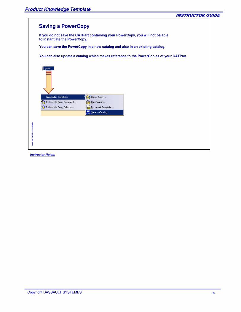
If you do not save the CATPart containing your PowerCopy, you will not be able to instantiate the PowerCopy.
Saving a PowerCopy
You can save the PowerCopy in a new catalog and also in an existing catalog.
You can also update a catalog which makes reference to the PowerCopies of your CATPart.
Instructor Notes:
Product Knowledge Template
Copyright DASSAULT SYSTEMES 31
��������������
Cop
yrig
ht D
AS
SA
ULT
SYS
TEM
ES
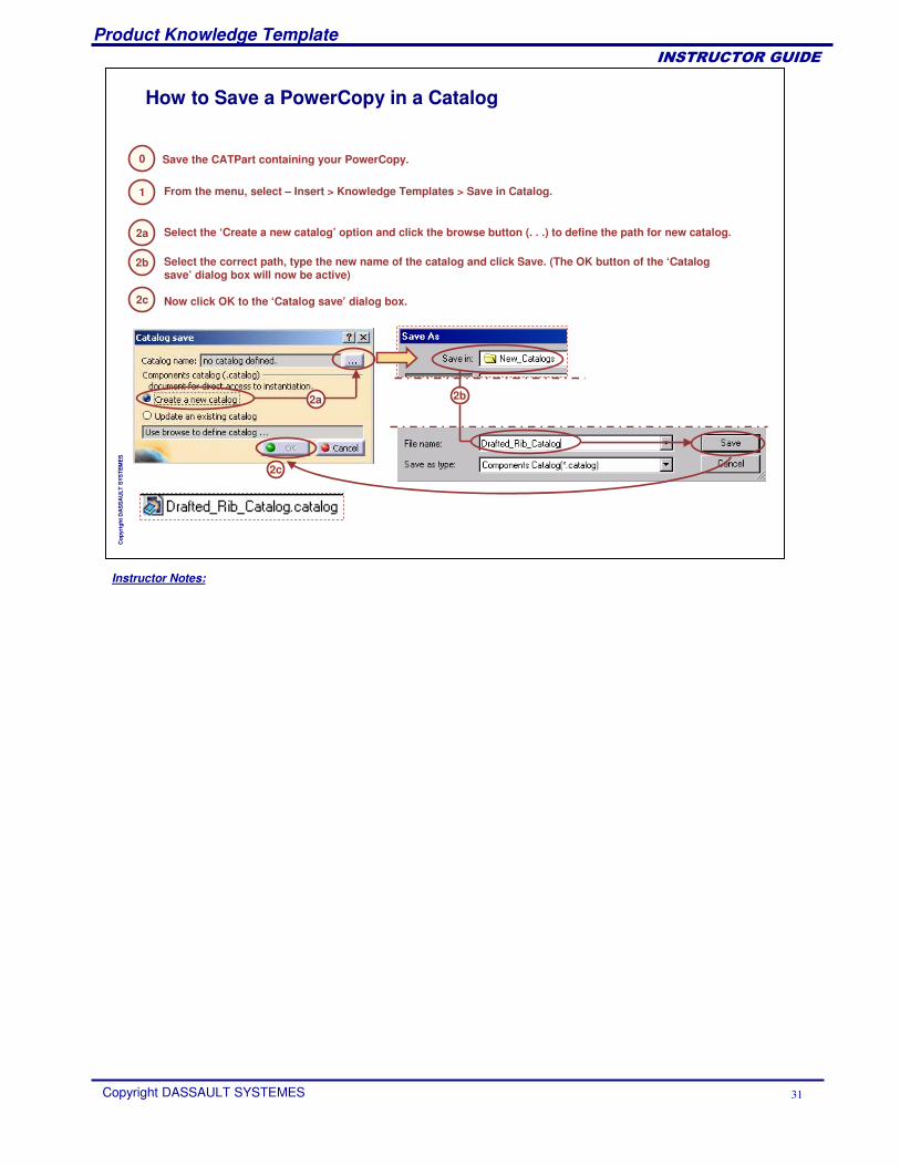
0
How to Save a PowerCopy in a Catalog
Save the CATPart containing your PowerCopy.
1 From the menu, select – Insert > Knowledge Templates > Save in Catalog.
2a Select the ‘Create a new catalog’ option and click the browse button (. . .) to define the path for new catalog.
2b Select the correct path, type the new name of the catalog and click Save. (The OK button of the ‘Catalog save’ dialog box will now be active)
2a 2b
2c Now click OK to the ‘Catalog save’ dialog box.
2c
Instructor Notes:
Product Knowledge Template
Copyright DASSAULT SYSTEMES 32
��������������
Cop
yrig
ht D
AS
SA
ULT
SYS
TEM
ES
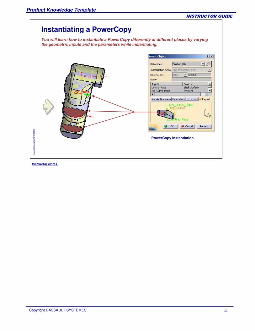
Instantiating a PowerCopyYou will learn how to instantiate a PowerCopy differently at different places by varying the geometric inputs and the parameters while instantiating.
PowerCopy instantiation
Instructor Notes:
Product Knowledge Template
Copyright DASSAULT SYSTEMES 33
��������������
Cop
yrig
ht D
AS
SA
ULT
SYS
TEM
ES
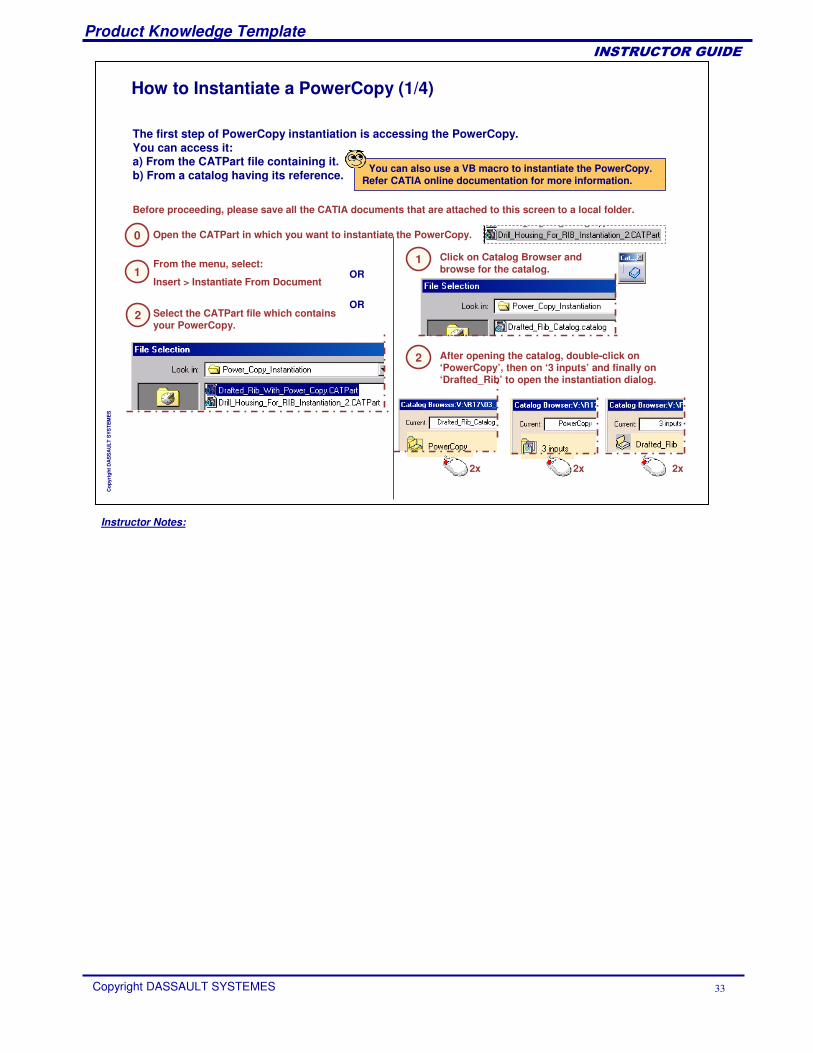
0
The first step of PowerCopy instantiation is accessing the PowerCopy. You can access it:a) From the CATPart file containing it. b) From a catalog having its reference.
1
How to Instantiate a PowerCopy (1/4)
From the menu, select:
Insert > Instantiate From Document
2 Select the CATPart file which contains your PowerCopy.
1 Click on Catalog Browser and browse for the catalog.
2 After opening the catalog, double-click on ‘PowerCopy’, then on ‘3 inputs’ and finally on ‘Drafted_Rib’ to open the instantiation dialog.
OR
OR
Before proceeding, please save all the CATIA documents that are attached to this screen to a local folder.
Open the CATPart in which you want to instantiate the PowerCopy.
2x 2x 2x
You can also use a VB macro to instantiate the PowerCopy. Refer CATIA online documentation for more information.
Instructor Notes:
Product Knowledge Template
Copyright DASSAULT SYSTEMES 34
��������������
Cop
yrig
ht D
AS
SA
ULT
SYS
TEM
ES
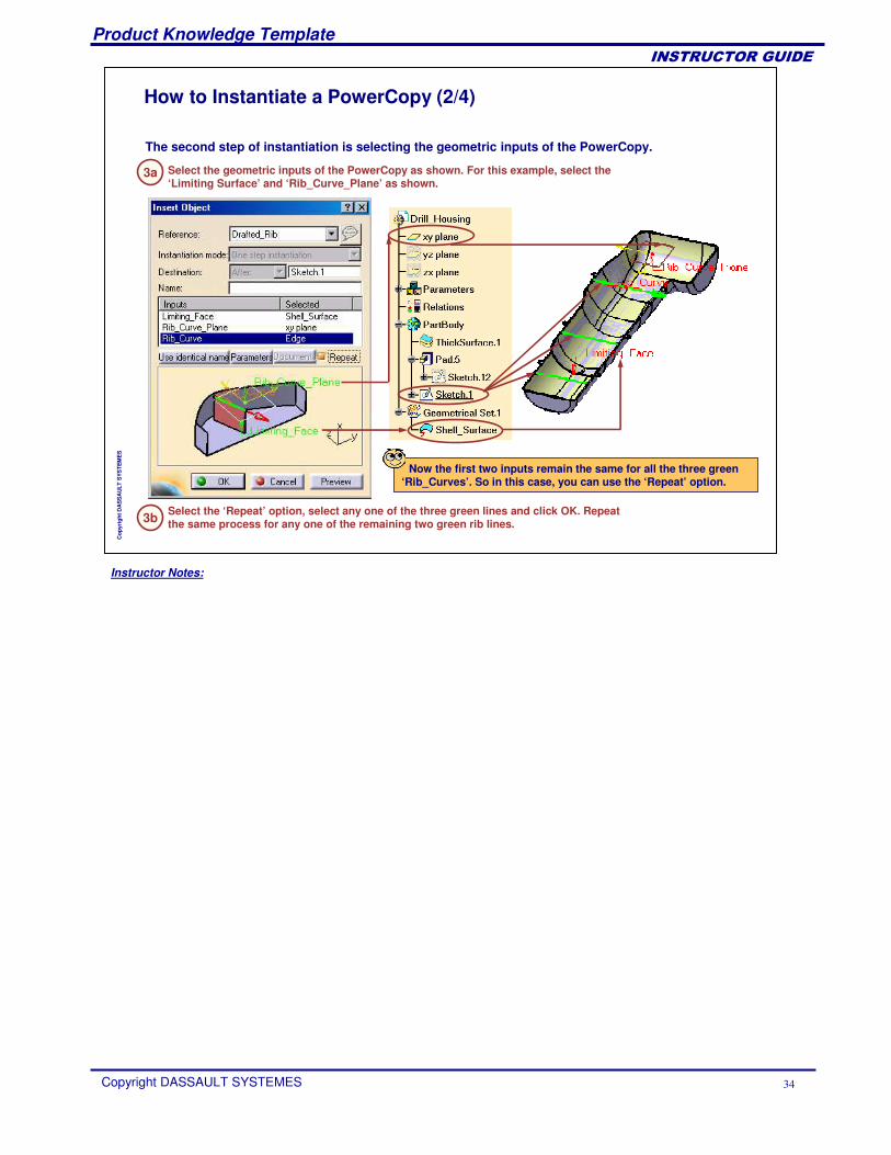
The second step of instantiation is selecting the geometric inputs of the PowerCopy.
3a
How to Instantiate a PowerCopy (2/4)
Select the geometric inputs of the PowerCopy as shown. For this example, select the ‘Limiting Surface’ and ‘Rib_Curve_Plane’ as shown.
Now the first two inputs remain the same for all the three green‘Rib_Curves’. So in this case, you can use the ‘Repeat’ option.
3b Select the ‘Repeat’ option, select any one of the three green lines and click OK. Repeat the same process for any one of the remaining two green rib lines.
Instructor Notes:
Product Knowledge Template
Copyright DASSAULT SYSTEMES 35
��������������
Cop
yrig
ht D
AS
SA
ULT
SYS
TEM
ES
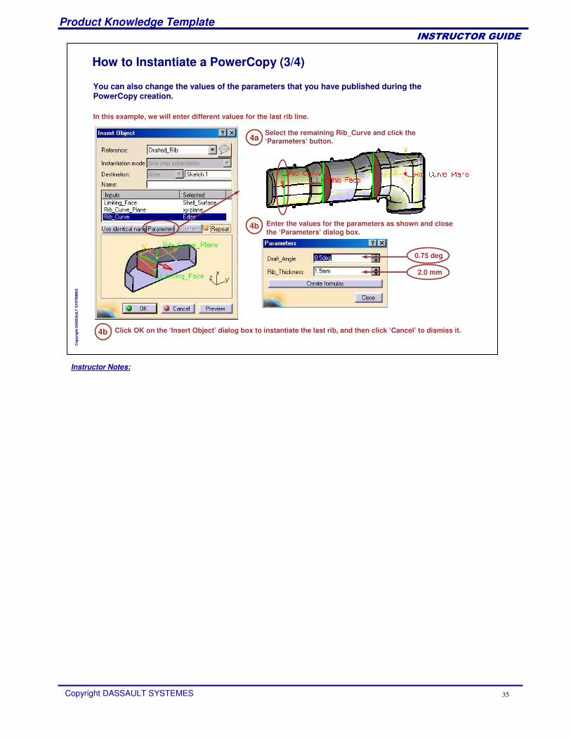
You can also change the values of the parameters that you have published during the PowerCopy creation.
4a
How to Instantiate a PowerCopy (3/4)
In this example, we will enter different values for the last rib line.
Enter the values for the parameters as shown and close the ‘Parameters’ dialog box.
0.75 deg
2.0 mm
Select the remaining Rib_Curve and click the ‘Parameters’ button.
4b
Click OK on the ‘Insert Object’ dialog box to instantiate the last rib, and then click ‘Cancel’ to dismiss it.4b
Instructor Notes:
Product Knowledge Template
Copyright DASSAULT SYSTEMES 36
��������������
Cop
yrig
ht D
AS
SA
ULT
SYS
TEM
ES
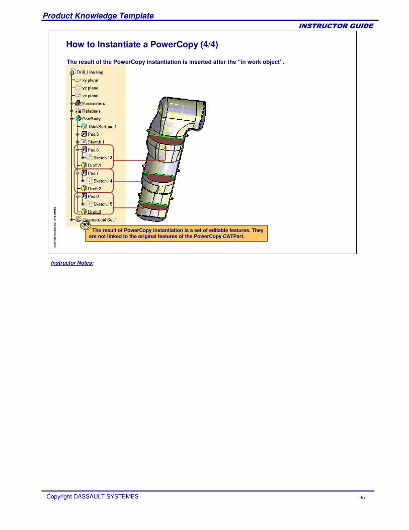
The result of the PowerCopy instantiation is inserted after the “in work object”.
How to Instantiate a PowerCopy (4/4)
The result of PowerCopy instantiation is a set of editable features. They are not linked to the original features of the PowerCopy CATPart.
Instructor Notes:
Product Knowledge Template
Copyright DASSAULT SYSTEMES 37
��������������
Cop
yrig
ht D
AS
SA
ULT
SYS
TEM
ES
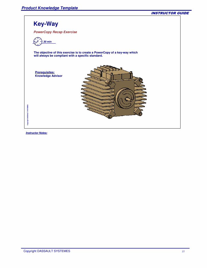
Key-WayPowerCopy Recap Exercise
30 min
The objective of this exercise is to create a PowerCopy of a key-way whichwill always be compliant with a specific standard.
Prerequisites:Knowledge Advisor
Instructor Notes:
Product Knowledge Template
Copyright DASSAULT SYSTEMES 38
��������������
Cop
yrig
ht D
AS
SA
ULT
SYS
TEM
ES
To Sum Up ...
What is a PowerCopyA PowerCopy is a set of design features grouped together to be reproduced. It is an advanced copy tool. PowerCopy tools are available in the Insert menu in Part design, Wireframe and surface, and Sheet metal design workbenches.
You have learned:
How to create a PowerCopyDuring creation, you have to set the definition, identify and name the inputs, publish the parameters, choose an icon and preview.
How to save a PowerCopySaving a PowerCopy is necessary. If not saved, a PowerCopy can never be instantiated. This can be done through Insert menu > Advanced replication tools > Save in catalog.
How to instantiate a PowerCopyFor instantiation, you have to first select a previously created PowerCopy. This can be done in two ways. The first way is through a catalog, and the second way is from Insert menu > Instantiate from document.
Instructor Notes:
Product Knowledge Template
Copyright DASSAULT SYSTEMES 39
��������������
Cop
yrig
ht D
AS
SA
ULT
SYS
TEM
ES
Creating and Using User Defined Features
User Defined Features: PresentationCreating a User Defined FeatureSaving a User Defined FeatureInstantiating a User Defined FeatureUDF Meta InputsUser Defined Features Recap Exercises
Instructor Notes:
Product Knowledge Template
Copyright DASSAULT SYSTEMES 40
��������������
Cop
yrig
ht D
AS
SA
ULT
SYS
TEM
ES
User Defined Features: PresentationYou will learn what are the benefits of advanced replication tools called User Defined Features.
Instructor Notes:
Product Knowledge Template
Copyright DASSAULT SYSTEMES 41
��������������
Cop
yrig
ht D
AS
SA
ULT
SYS
TEM
ES
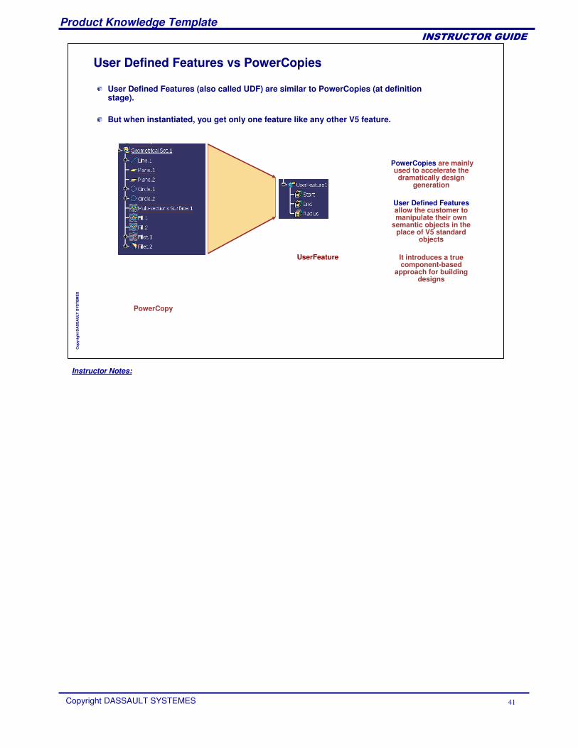
User Defined Features (also called UDF) are similar to PowerCopies (at definitionstage).
But when instantiated, you get only one feature like any other V5 feature.
PowerCopies are mainly used to accelerate the
dramatically design generation
User Defined Featuresallow the customer to manipulate their own
semantic objects in the place of V5 standard
objects
It introduces a true component-based
approach for building designs
User Defined Features vs PowerCopies
PowerCopy
UserFeature
Instructor Notes:
Product Knowledge Template
Copyright DASSAULT SYSTEMES 42
��������������
Cop
yrig
ht D
AS
SA
ULT
SYS
TEM
ES
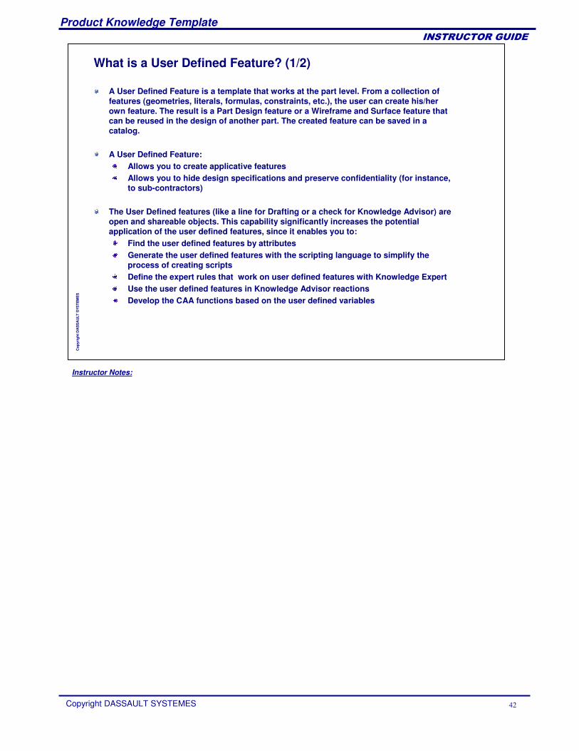
What is a User Defined Feature? (1/2)
A User Defined Feature is a template that works at the part level. From a collection of features (geometries, literals, formulas, constraints, etc.), the user can create his/her own feature. The result is a Part Design feature or a Wireframe and Surface feature that can be reused in the design of another part. The created feature can be saved in a catalog.
A User Defined Feature:Allows you to create applicative features Allows you to hide design specifications and preserve confidentiality (for instance, to sub-contractors)
The User Defined features (like a line for Drafting or a check for Knowledge Advisor) are open and shareable objects. This capability significantly increases the potential application of the user defined features, since it enables you to:
Find the user defined features by attributes Generate the user defined features with the scripting language to simplify the process of creating scripts Define the expert rules that work on user defined features with Knowledge Expert Use the user defined features in Knowledge Advisor reactions Develop the CAA functions based on the user defined variables
Instructor Notes:
Product Knowledge Template
Copyright DASSAULT SYSTEMES 43
��������������
Cop
yrig
ht D
AS
SA
ULT
SYS
TEM
ES
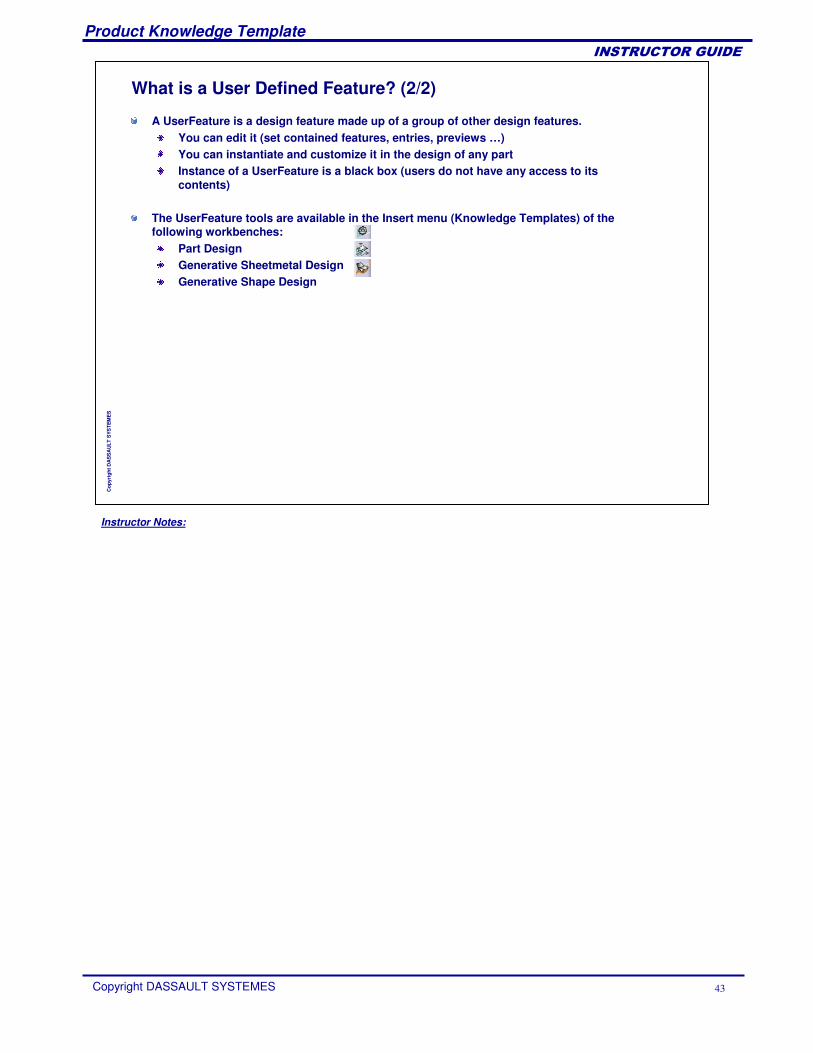
A UserFeature is a design feature made up of a group of other design features.You can edit it (set contained features, entries, previews …)You can instantiate and customize it in the design of any partInstance of a UserFeature is a black box (users do not have any access to itscontents)
The UserFeature tools are available in the Insert menu (Knowledge Templates) of the following workbenches:
Part DesignGenerative Sheetmetal DesignGenerative Shape Design
What is a User Defined Feature? (2/2)
Instructor Notes:
Product Knowledge Template
Copyright DASSAULT SYSTEMES 44
��������������
Cop
yrig
ht D
AS
SA
ULT
SYS
TEM
ES
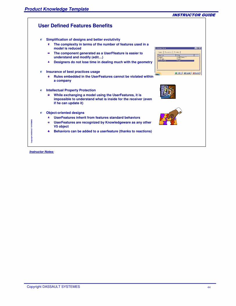
User Defined Features Benefits
Simplification of designs and better evolutivityThe complexity in terms of the number of features used in a model is reducedThe component generated as a UserFfeature is easier to understand and modify (edit…)Designers do not lose time in dealing much with the geometry
Insurance of best practices usageRules embedded in the UserFeatures cannot be violated within a company
Intellectual Property ProtectionWhile exchanging a model using the UserFeatures, it is impossible to understand what is inside for the receiver (even if he can update it)
Object-oriented designsUserFeatures inherit from features standard behaviorsUserFeatures are recognized by Knowledgeware as any other V5 objectBehaviors can be added to a userfeature (thanks to reactions)
Instructor Notes:
Product Knowledge Template
Copyright DASSAULT SYSTEMES 45
��������������
Cop
yrig
ht D
AS
SA
ULT
SYS
TEM
ES
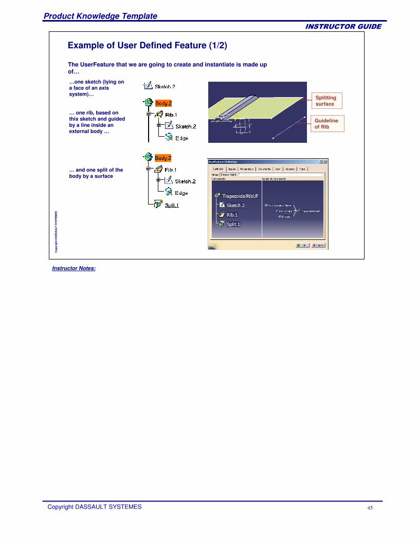
Example of User Defined Feature (1/2)
The UserFeature that we are going to create and instantiate is made up of…
…one sketch (lying on a face of an axis system)…
… one rib, based on this sketch and guidedby a line inside an external body …
… and one split of the body by a surface
Guideline of Rib
Splittingsurface
Instructor Notes:
Product Knowledge Template
Copyright DASSAULT SYSTEMES 46
��������������
Cop
yrig
ht D
AS
SA
ULT
SYS
TEM
ES
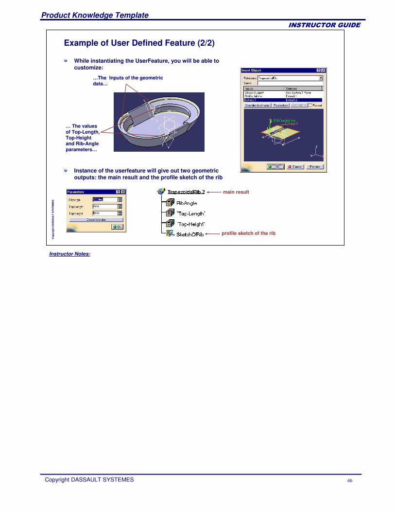
Example of User Defined Feature (2/2)
While instantiating the UserFeature, you will be able to customize:
…The Inputs of the geometricdata…
… The values of Top-Length, Top-Heightand Rib-Angle parameters…
Instance of the userfeature will give out two geometricoutputs: the main result and the profile sketch of the rib
main result
profile sketch of the rib
Instructor Notes:
Product Knowledge Template
Copyright DASSAULT SYSTEMES 47
��������������
Cop
yrig
ht D
AS
SA
ULT
SYS
TEM
ES
Creating a User Defined FeatureYou will learn how to group the existing features in a black box in order to reuse them in another context.
Instructor Notes:
Product Knowledge Template
Copyright DASSAULT SYSTEMES 48
��������������
Cop
yrig
ht D
AS
SA
ULT
SYS
TEM
ES
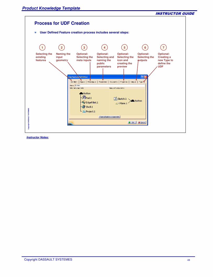
Process for UDF Creation
User Defined Feature creation process includes several steps:
Selecting the existing features
Naming the input geometry
Optional: Selecting and naming the public parameters
Optional: Selecting the icon and creating the preview
Optional: Selecting the outputs
Optional:Creating a new Type to define the UDF
2 4 5 6 71
Optional:Selecting the meta inputs
3
Instructor Notes:
Product Knowledge Template
Copyright DASSAULT SYSTEMES 49
��������������
Cop
yrig
ht D
AS
SA
ULT
SYS
TEM
ES
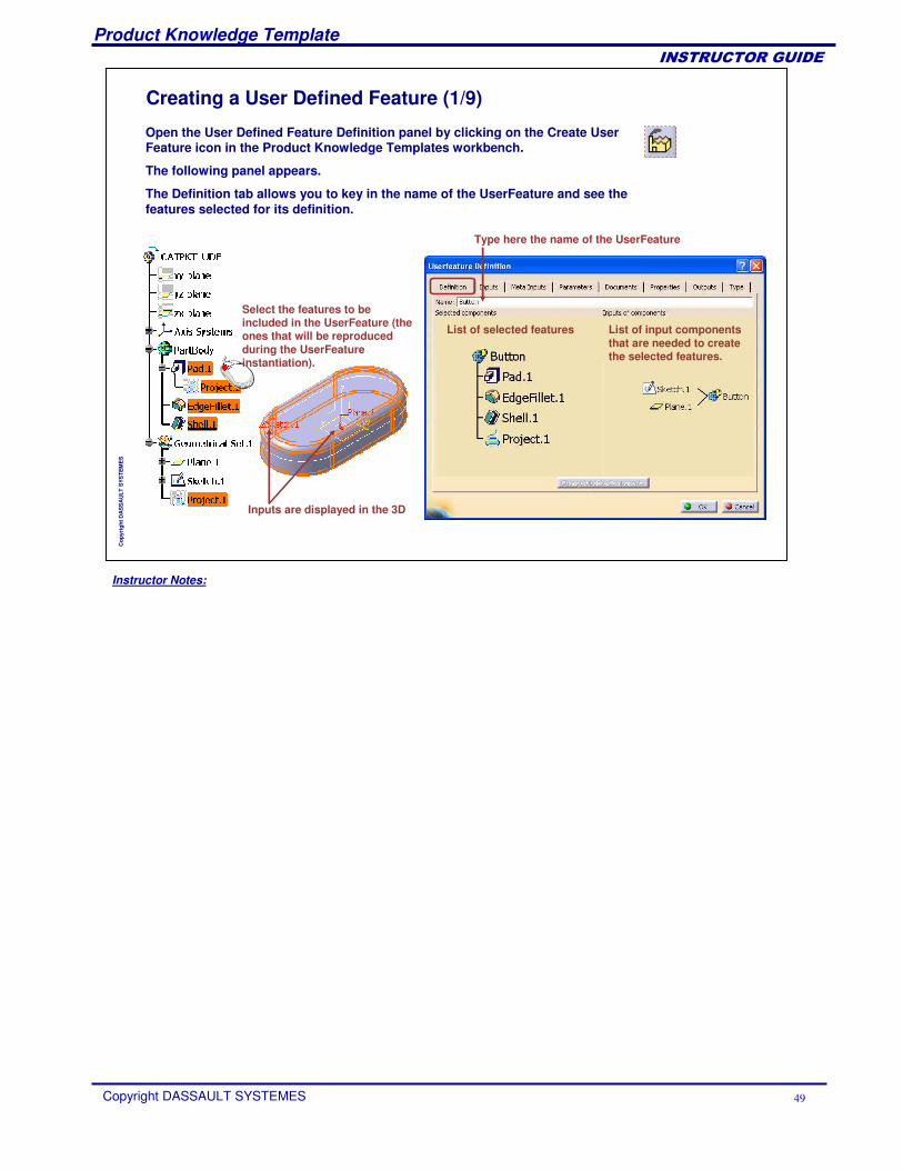
Creating a User Defined Feature (1/9)
Open the User Defined Feature Definition panel by clicking on the Create User Feature icon in the Product Knowledge Templates workbench.
The following panel appears.
The Definition tab allows you to key in the name of the UserFeature and see the features selected for its definition.
Select the features to be included in the UserFeature (the ones that will be reproduced during the UserFeatureinstantiation).
List of selected features List of input components that are needed to create the selected features.
Type here the name of the UserFeature
Inputs are displayed in the 3D
Instructor Notes:
Product Knowledge Template
Copyright DASSAULT SYSTEMES 50
��������������
Cop
yrig
ht D
AS
SA
ULT
SYS
TEM
ES
Creating a User Defined Feature (2/9)
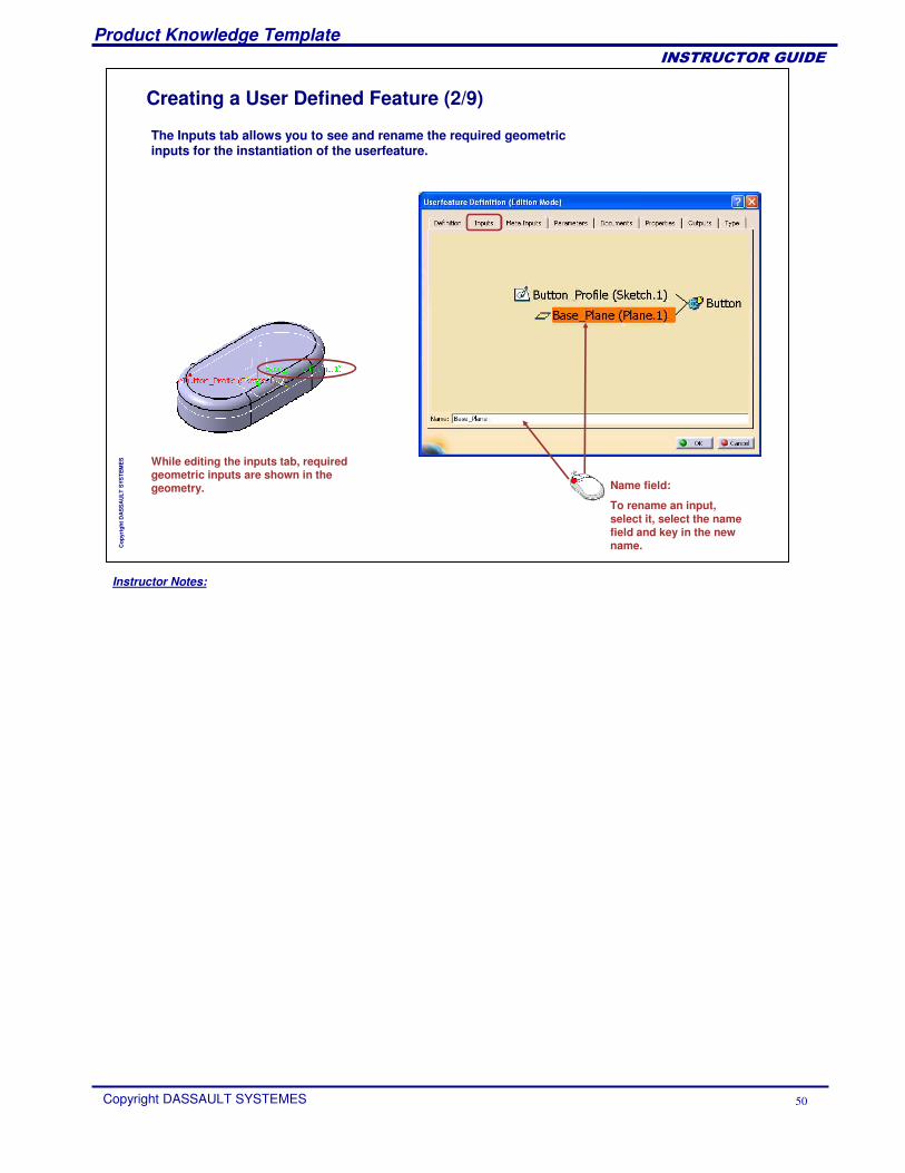
The Inputs tab allows you to see and rename the required geometricinputs for the instantiation of the userfeature.
While editing the inputs tab, requiredgeometric inputs are shown in the geometry. Name field:
To rename an input, select it, select the namefield and key in the new name.
Instructor Notes:
Product Knowledge Template
Copyright DASSAULT SYSTEMES 51
��������������
Cop
yrig
ht D
AS
SA
ULT
SYS
TEM
ES
Creating a User Defined Feature (3/9)
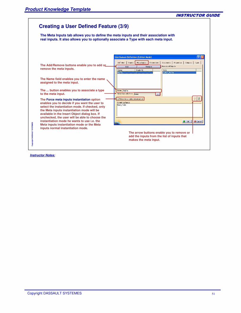
The Meta Inputs tab allows you to define the meta inputs and their association with real inputs. It also allows you to optionally associate a Type with each meta input.
The ... button enables you to associate a type to the meta input.
The Force meta inputs instantiation option enables you to decide if you want the user to select the instantiation mode. If checked, only the Meta inputs instantiation mode will be available in the Insert Object dialog box. If unchecked, the user will be able to choose the instantiation mode he wants to use i.e. the Meta inputs instantiation mode or the Meta inputs normal instantiation mode.
The Add/Remove buttons enable you to add or remove the meta inputs.
The arrow buttons enable you to remove or add the inputs from the list of inputs that makes the meta input.
The Name field enables you to enter the name assigned to the meta input.
Instructor Notes:
Product Knowledge Template
Copyright DASSAULT SYSTEMES 52
��������������
Cop
yrig
ht D
AS
SA
ULT
SYS
TEM
ES
Creating a User Defined Feature (4/9)
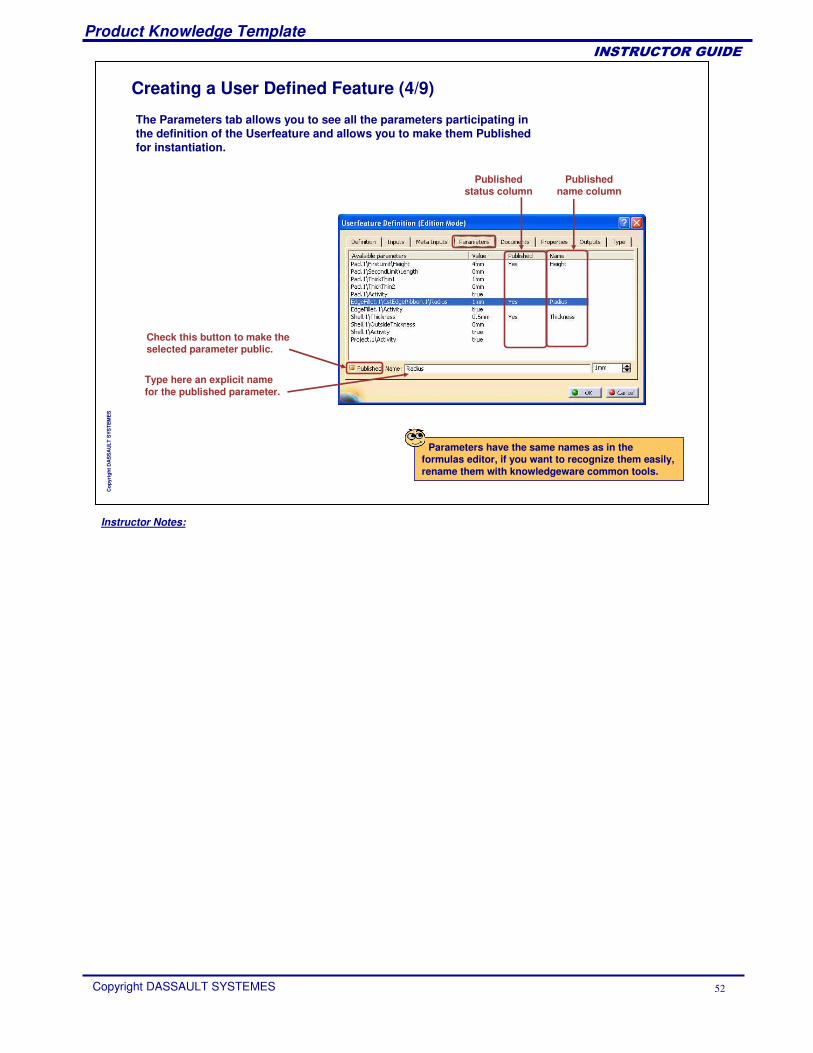
Type here an explicit namefor the published parameter.
Check this button to make the selected parameter public.
Publishedstatus column
Publishedname column
The Parameters tab allows you to see all the parameters participating in the definition of the Userfeature and allows you to make them Publishedfor instantiation.
Parameters have the same names as in the formulas editor, if you want to recognize them easily, rename them with knowledgeware common tools.
Instructor Notes:
Product Knowledge Template
Copyright DASSAULT SYSTEMES 53
��������������
Cop
yrig
ht D
AS
SA
ULT
SYS
TEM
ES
Creating a User Defined Feature (5/9)
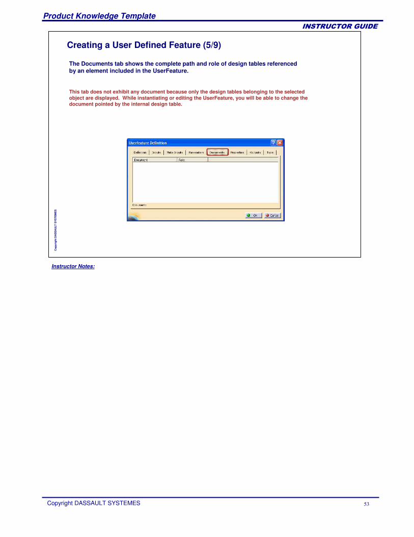
The Documents tab shows the complete path and role of design tables referenced by an element included in the UserFeature.
This tab does not exhibit any document because only the design tables belonging to the selected object are displayed. While instantiating or editing the UserFeature, you will be able to change the document pointed by the internal design table.
Instructor Notes:
Product Knowledge Template
Copyright DASSAULT SYSTEMES 54
��������������
Cop
yrig
ht D
AS
SA
ULT
SYS
TEM
ES
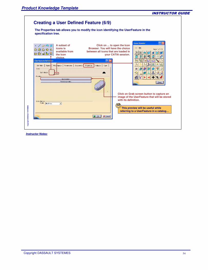
Creating a User Defined Feature (6/9)
This preview will be useful while referring to a UserFeature in a catalog…
The Properties tab allows you to modify the icon identifying the UserFeature in the specification tree.
Click on Grab screen button to capture an image of the UserFeature that will be stored with its definition.
A subset of icons is available from the Icon choice.
Click on ... to open the Icon Browser. You will have the choice
between all icons that are loaded in your CATIA session.
Instructor Notes:
Product Knowledge Template
Copyright DASSAULT SYSTEMES 55
��������������
Cop
yrig
ht D
AS
SA
ULT
SYS
TEM
ES
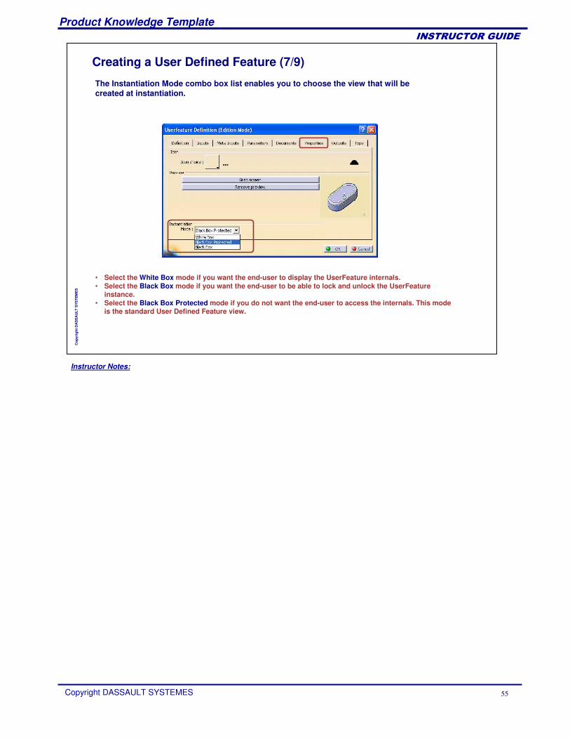
Creating a User Defined Feature (7/9)
The Instantiation Mode combo box list enables you to choose the view that will be created at instantiation.
• Select the White Box mode if you want the end-user to display the UserFeature internals. • Select the Black Box mode if you want the end-user to be able to lock and unlock the UserFeature
instance. • Select the Black Box Protected mode if you do not want the end-user to access the internals. This mode
is the standard User Defined Feature view.
Instructor Notes:
Product Knowledge Template
Copyright DASSAULT SYSTEMES 56
��������������
Cop
yrig
ht D
AS
SA
ULT
SYS
TEM
ES
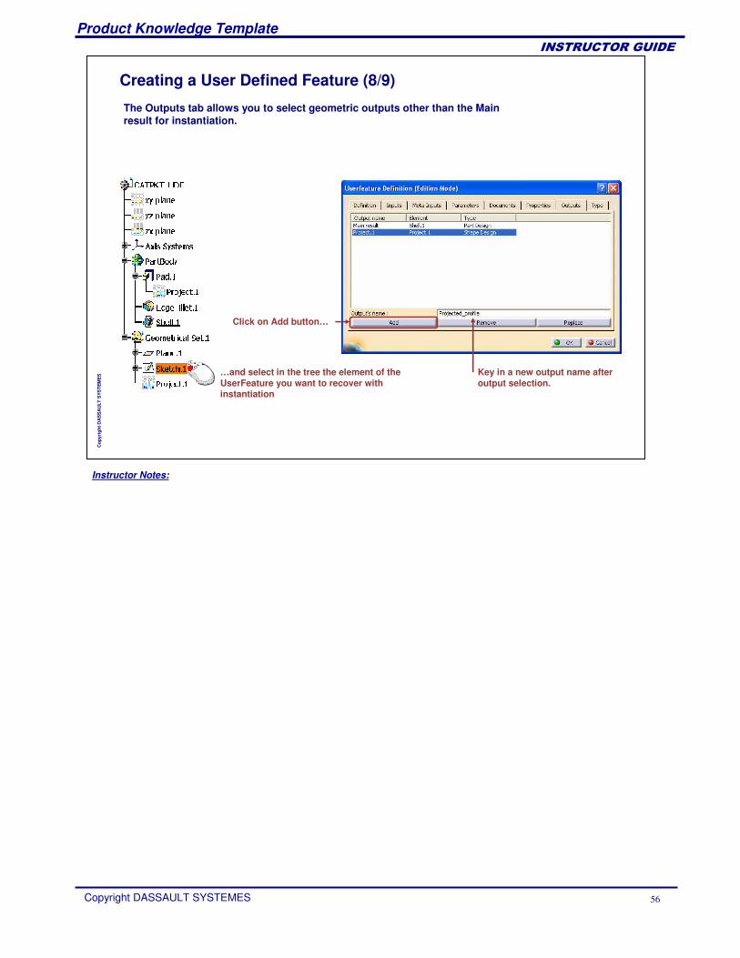
Creating a User Defined Feature (8/9)
The Outputs tab allows you to select geometric outputs other than the Main result for instantiation.
Click on Add button…
…and select in the tree the element of the UserFeature you want to recover withinstantiation
Key in a new output name afteroutput selection.
Instructor Notes:
Product Knowledge Template
Copyright DASSAULT SYSTEMES 57
��������������
Cop
yrig
ht D
AS
SA
ULT
SYS
TEM
ES
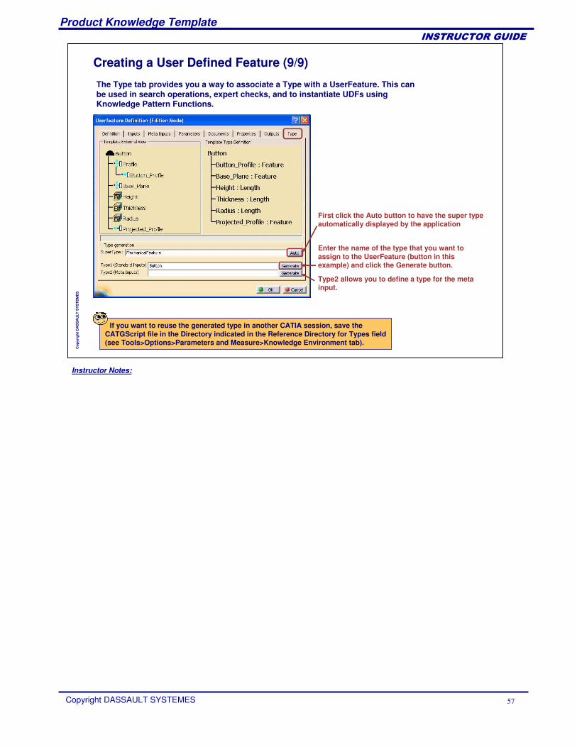
Creating a User Defined Feature (9/9)
The Type tab provides you a way to associate a Type with a UserFeature. This can be used in search operations, expert checks, and to instantiate UDFs using Knowledge Pattern Functions.
If you want to reuse the generated type in another CATIA session, save the CATGScript file in the Directory indicated in the Reference Directory for Types field (see Tools>Options>Parameters and Measure>Knowledge Environment tab).
First click the Auto button to have the super type automatically displayed by the application
Enter the name of the type that you want to assign to the UserFeature (button in this example) and click the Generate button.
Type2 allows you to define a type for the meta input.
Instructor Notes:
Product Knowledge Template
Copyright DASSAULT SYSTEMES 58
��������������
Cop
yrig
ht D
AS
SA
ULT
SYS
TEM
ES
Saving a User Defined FeatureYou will learn how to store a User Defined Feature in a catalog document in order to make it available for other users.
Instructor Notes:
Product Knowledge Template
Copyright DASSAULT SYSTEMES 59
��������������
Cop
yrig
ht D
AS
SA
ULT
SYS
TEM
ES
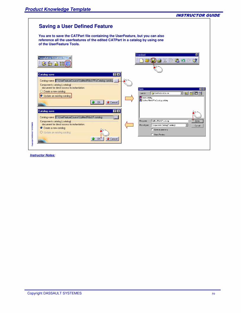
Saving a User Defined Feature
You are to save the CATPart file containing the UserFeature, but you can alsoreference all the userfeatures of the edited CATPart in a catalog by using one of the UserFeature Tools.
Instructor Notes:
Product Knowledge Template
Copyright DASSAULT SYSTEMES 60
��������������
Cop
yrig
ht D
AS
SA
ULT
SYS
TEM
ES
Instantiating a User Defined FeatureYou will learn how to import an existing User Defined Feature from a catalog in your document, and how to make it fit to the specifications of your design.
Instructor Notes:
Product Knowledge Template
Copyright DASSAULT SYSTEMES 61
��������������
Cop
yrig
ht D
AS
SA
ULT
SYS
TEM
ES
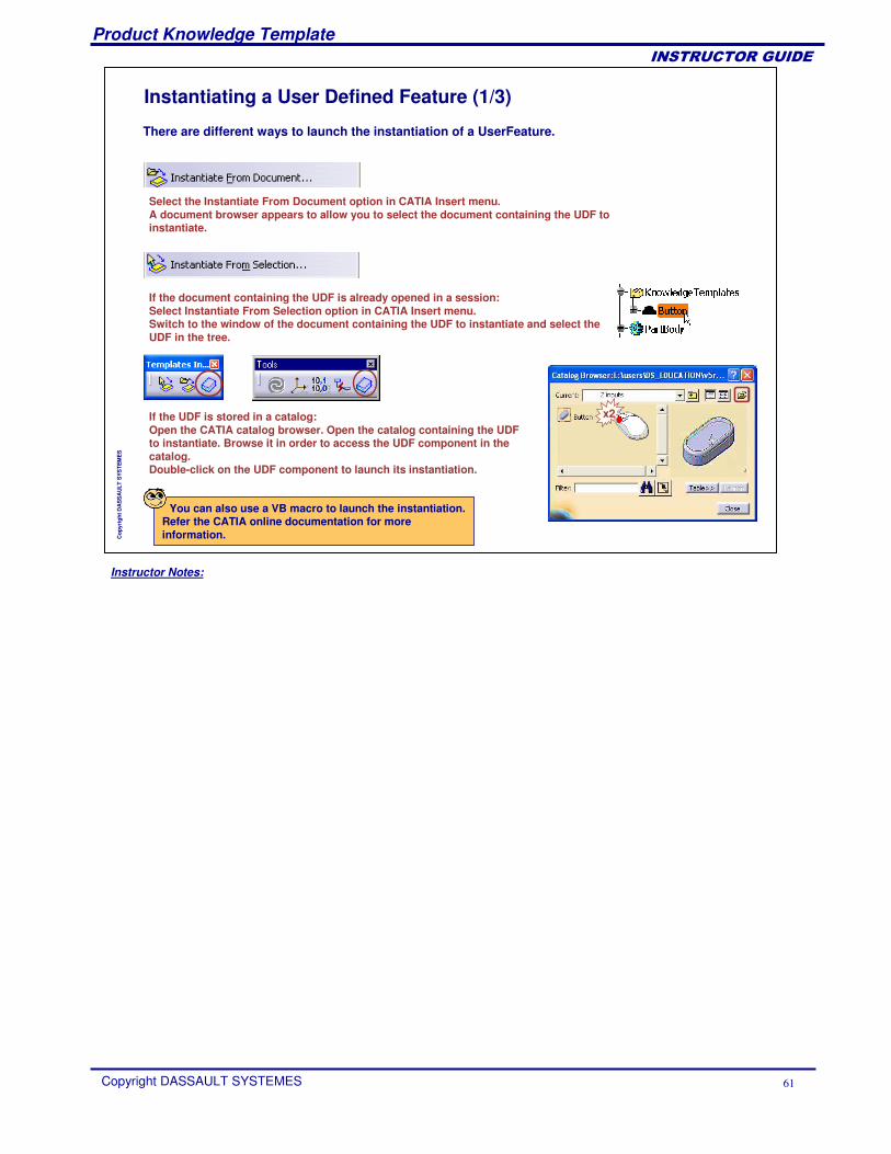
Instantiating a User Defined Feature (1/3)
There are different ways to launch the instantiation of a UserFeature.
Select the Instantiate From Document option in CATIA Insert menu. A document browser appears to allow you to select the document containing the UDF to instantiate.
If the document containing the UDF is already opened in a session:Select Instantiate From Selection option in CATIA Insert menu. Switch to the window of the document containing the UDF to instantiate and select the UDF in the tree.
You can also use a VB macro to launch the instantiation. Refer the CATIA online documentation for more information.
If the UDF is stored in a catalog:Open the CATIA catalog browser. Open the catalog containing the UDF to instantiate. Browse it in order to access the UDF component in the catalog.Double-click on the UDF component to launch its instantiation.
x2
Instructor Notes:
Product Knowledge Template
Copyright DASSAULT SYSTEMES 62
��������������
Cop
yrig
ht D
AS
SA
ULT
SYS
TEM
ES
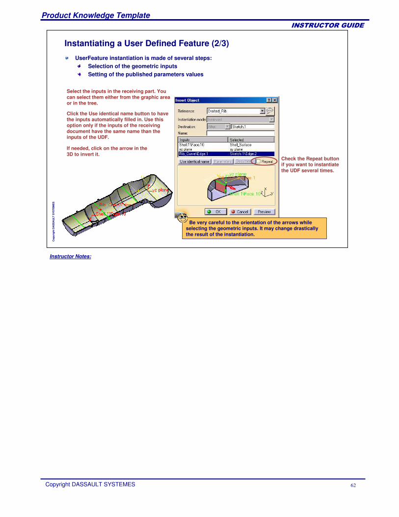
Instantiating a User Defined Feature (2/3)
UserFeature instantiation is made of several steps:Selection of the geometric inputsSetting of the published parameters values
Select the inputs in the receiving part. You can select them either from the graphic area or in the tree.
Click the Use identical name button to have the inputs automatically filled in. Use this option only if the inputs of the receiving document have the same name than the inputs of the UDF.
Check the Repeat button if you want to instantiate the UDF several times.
Be very careful to the orientation of the arrows while selecting the geometric inputs. It may change drastically the result of the instantiation.
If needed, click on the arrow in the 3D to invert it.
Instructor Notes:
Product Knowledge Template
Copyright DASSAULT SYSTEMES 63
��������������
Cop
yrig
ht D
AS
SA
ULT
SYS
TEM
ES
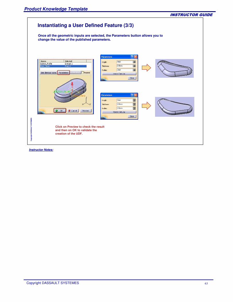
Instantiating a User Defined Feature (3/3)
Once all the geometric inputs are selected, the Parameters button allows you to change the value of the published parameters.
Click on Preview to check the result and then on OK to validate the creation of the UDF.
Instructor Notes:
Product Knowledge Template
Copyright DASSAULT SYSTEMES 64
��������������
Cop
yrig
ht D
AS
SA
ULT
SYS
TEM
ES
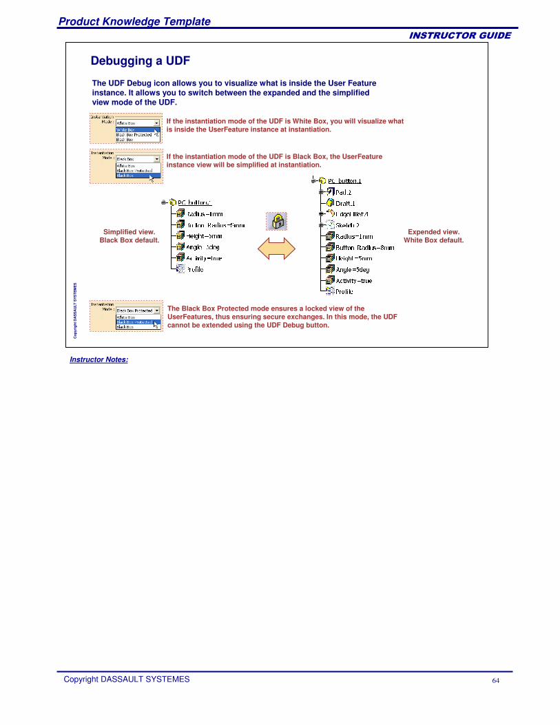
Debugging a UDF
If the instantiation mode of the UDF is White Box, you will visualize what is inside the UserFeature instance at instantiation.
The Black Box Protected mode ensures a locked view of the UserFeatures, thus ensuring secure exchanges. In this mode, the UDF cannot be extended using the UDF Debug button.
If the instantiation mode of the UDF is Black Box, the UserFeatureinstance view will be simplified at instantiation.
The UDF Debug icon allows you to visualize what is inside the User Feature instance. It allows you to switch between the expanded and the simplified view mode of the UDF.
Simplified view.Black Box default.
Expended view.White Box default.
Instructor Notes:
Product Knowledge Template
Copyright DASSAULT SYSTEMES 65
��������������
Cop
yrig
ht D
AS
SA
ULT
SYS
TEM
ES
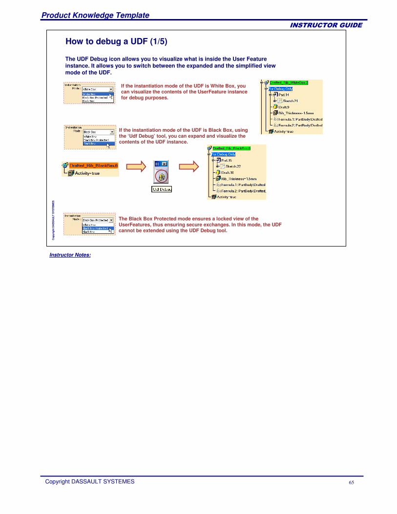
How to debug a UDF (1/5)
If the instantiation mode of the UDF is White Box, you can visualize the contents of the UserFeature instance for debug purposes.
The Black Box Protected mode ensures a locked view of the UserFeatures, thus ensuring secure exchanges. In this mode, the UDF cannot be extended using the UDF Debug tool.
If the instantiation mode of the UDF is Black Box, using the ‘Udf Debug’ tool, you can expand and visualize the contents of the UDF instance.
The UDF Debug icon allows you to visualize what is inside the User Feature instance. It allows you to switch between the expanded and the simplified view mode of the UDF.
Instructor Notes:
Product Knowledge Template
Copyright DASSAULT SYSTEMES 66
��������������
Cop
yrig
ht D
AS
SA
ULT
SYS
TEM
ES
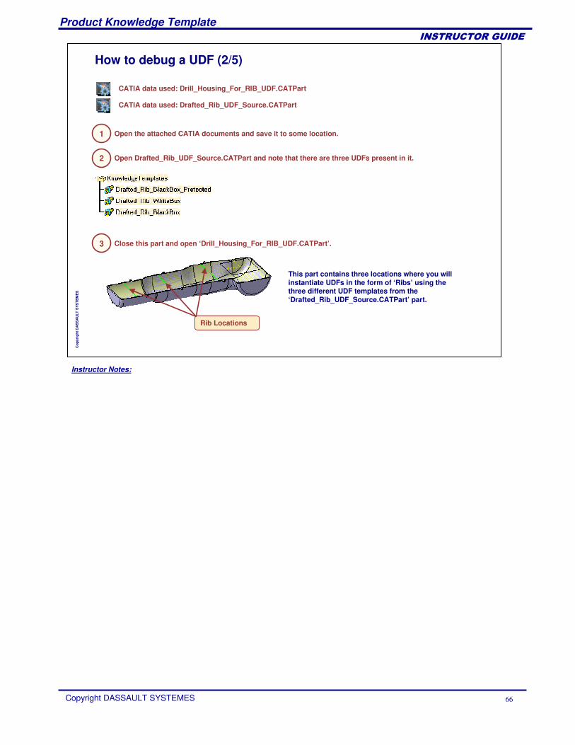
How to debug a UDF (2/5)
1 Open the attached CATIA documents and save it to some location.
CATIA data used: Drill_Housing_For_RIB_UDF.CATPart
CATIA data used: Drafted_Rib_UDF_Source.CATPart
2 Open Drafted_Rib_UDF_Source.CATPart and note that there are three UDFs present in it.
This part contains three locations where you will instantiate UDFs in the form of ‘Ribs’ using the three different UDF templates from the ‘Drafted_Rib_UDF_Source.CATPart’ part.
3 Close this part and open ‘Drill_Housing_For_RIB_UDF.CATPart’.
Rib Locations
Instructor Notes:
Product Knowledge Template
Copyright DASSAULT SYSTEMES 67
��������������
Cop
yrig
ht D
AS
SA
ULT
SYS
TEM
ES
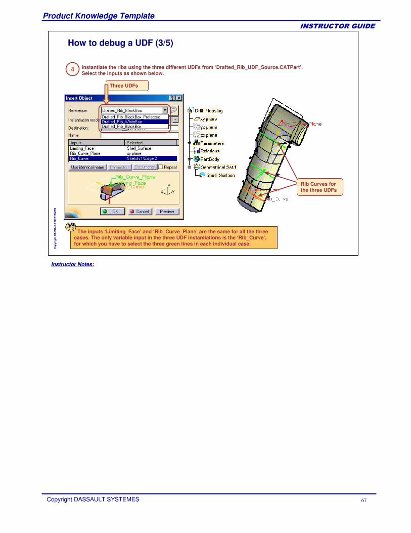
How to debug a UDF (3/5)
4 Instantiate the ribs using the three different UDFs from ‘Drafted_Rib_UDF_Source.CATPart’. Select the inputs as shown below.
Three UDFs
The inputs ‘Limiting_Face’ and ‘Rib_Curve_Plane’ are the same for all the three cases. The only variable input in the three UDF instantiations is the ‘Rib_Curve’, for which you have to select the three green lines in each individual case.
Rib Curves for the three UDFs
Instructor Notes:
Product Knowledge Template
Copyright DASSAULT SYSTEMES 68
��������������
Cop
yrig
ht D
AS
SA
ULT
SYS
TEM
ES
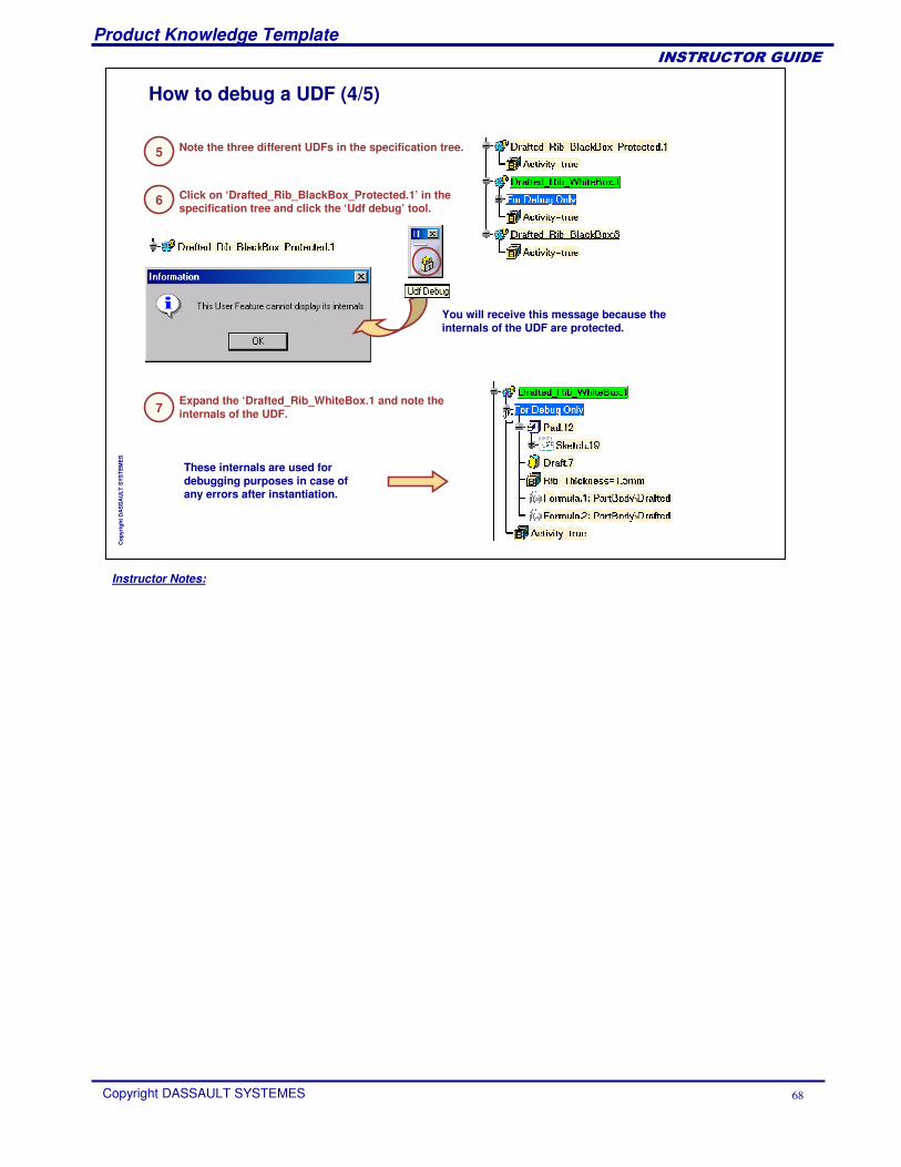
How to debug a UDF (4/5)
5 Note the three different UDFs in the specification tree.
6 Click on ‘Drafted_Rib_BlackBox_Protected.1’ in the specification tree and click the ‘Udf debug’ tool.
You will receive this message because the internals of the UDF are protected.
7 Expand the ‘Drafted_Rib_WhiteBox.1 and note the internals of the UDF.
These internals are used for debugging purposes in case of any errors after instantiation.
Instructor Notes:
Product Knowledge Template
Copyright DASSAULT SYSTEMES 69
��������������
Cop
yrig
ht D
AS
SA
ULT
SYS
TEM
ES
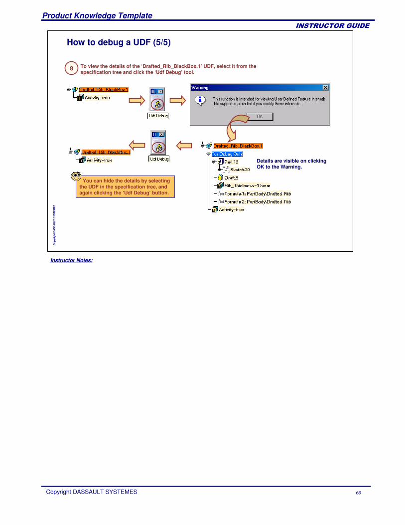
How to debug a UDF (5/5)
8 To view the details of the ‘Drafted_Rib_BlackBox.1’ UDF, select it from the specification tree and click the ‘Udf Debug’ tool.
Details are visible on clicking OK to the Warning.
You can hide the details by selecting the UDF in the specification tree, and again clicking the ‘Udf Debug’ button.
Instructor Notes:
Product Knowledge Template
Copyright DASSAULT SYSTEMES 70
��������������
Cop
yrig
ht D
AS
SA
ULT
SYS
TEM
ES
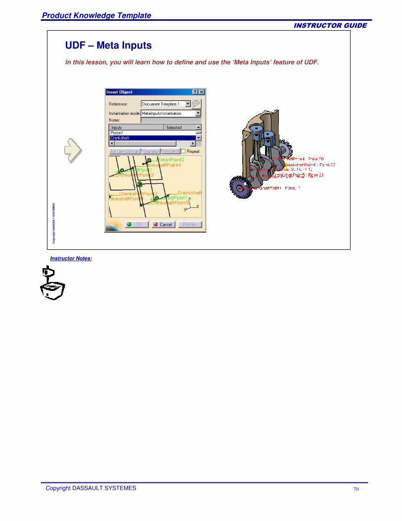
UDF – Meta Inputs
In this lesson, you will learn how to define and use the ‘Meta Inputs’ feature of UDF.
Instructor Notes:
Product Knowledge Template
Copyright DASSAULT SYSTEMES 71
��������������
Cop
yrig
ht D
AS
SA
ULT
SYS
TEM
ES
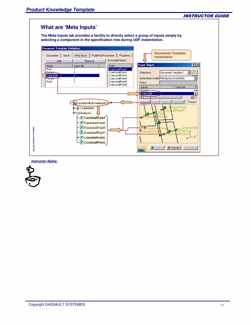
What are ‘Meta Inputs’The Meta Inputs tab provides a facility to directly select a group of inputs simply by selecting a component in the specification tree during UDF instantiation.
Documents Template Instantiation
Instructor Notes:
Product Knowledge Template
Copyright DASSAULT SYSTEMES 72
��������������
Cop
yrig
ht D
AS
SA
ULT
SYS
TEM
ES
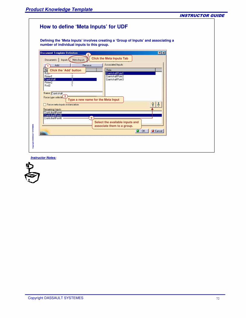
How to define ‘Meta Inputs’ for UDF
Defining the ‘Meta Inputs’ involves creating a ‘Group of Inputs’ and associating a number of individual inputs to this group.
Click the Meta Inputs Tab
Click the ‘Add’ button
0
1
Type a new name for the Meta Input2
Select the available inputs and associate them to a group.
3
Instructor Notes:
Product Knowledge Template
Copyright DASSAULT SYSTEMES 73
��������������
Cop
yrig
ht D
AS
SA
ULT
SYS
TEM
ES
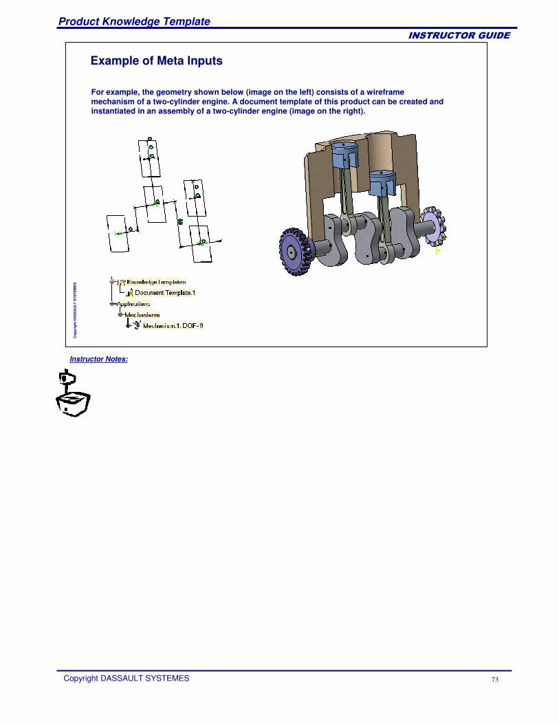
Example of Meta Inputs
For example, the geometry shown below (image on the left) consists of a wireframe mechanism of a two-cylinder engine. A document template of this product can be created and instantiated in an assembly of a two-cylinder engine (image on the right).
Instructor Notes:
Product Knowledge Template
Copyright DASSAULT SYSTEMES 74
��������������
Cop
yrig
ht D
AS
SA
ULT
SYS
TEM
ES
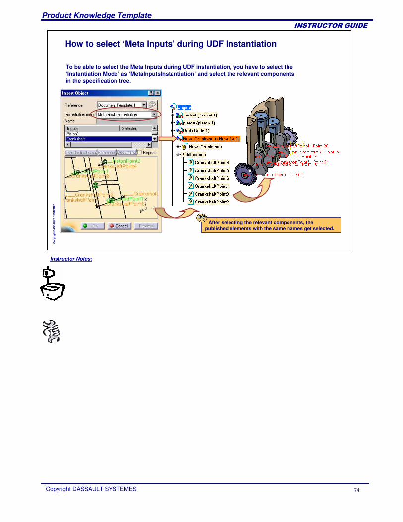
How to select ‘Meta Inputs’ during UDF Instantiation
To be able to select the Meta Inputs during UDF instantiation, you have to select the ‘Instantiation Mode’ as ‘MetaInputsInstantiation’ and select the relevant components in the specification tree.
After selecting the relevant components, the published elements with the same names get selected.
Instructor Notes:
Product Knowledge Template
Copyright DASSAULT SYSTEMES 75
��������������
Cop
yrig
ht D
AS
SA
ULT
SYS
TEM
ES
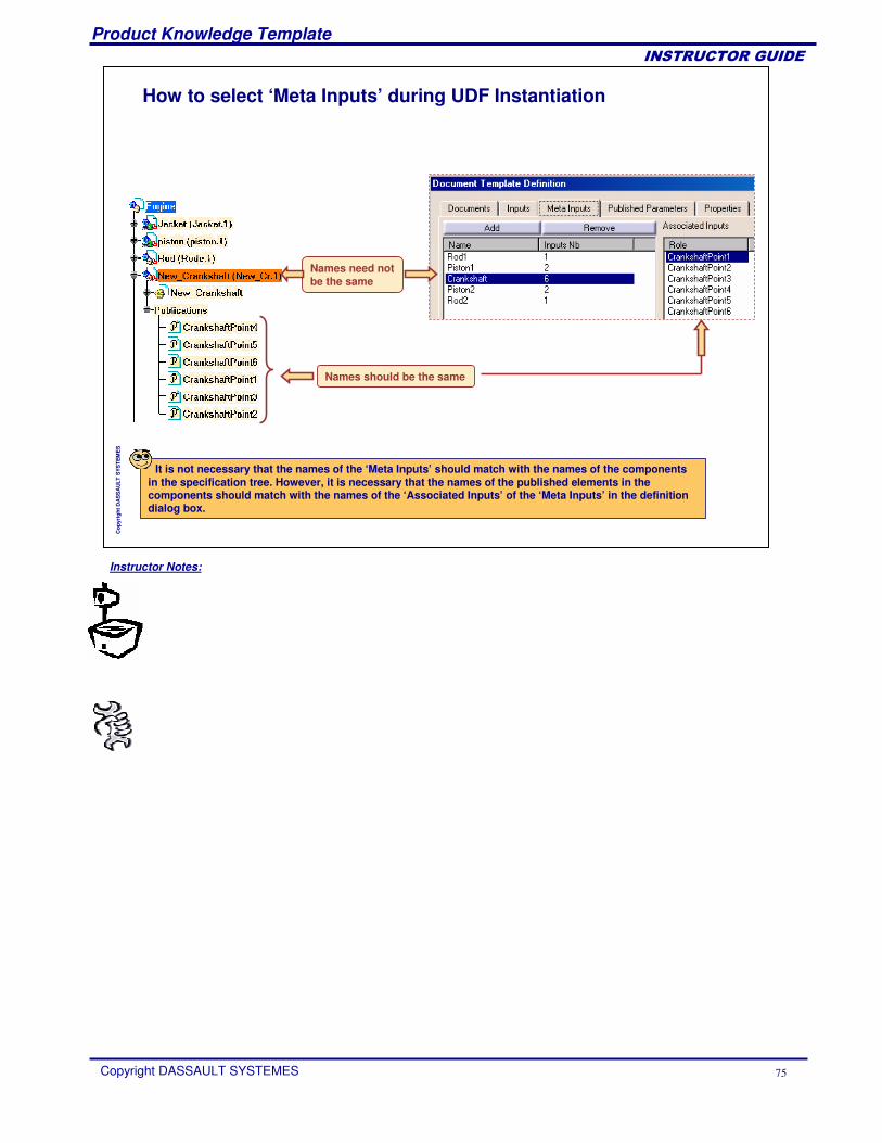
How to select ‘Meta Inputs’ during UDF Instantiation
It is not necessary that the names of the ‘Meta Inputs’ should match with the names of the components in the specification tree. However, it is necessary that the names of the published elements in the components should match with the names of the ‘Associated Inputs’ of the ‘Meta Inputs’ in the definition dialog box.
Names need not be the same
Names should be the same
Instructor Notes:
Product Knowledge Template
Copyright DASSAULT SYSTEMES 76
��������������
Cop
yrig
ht D
AS
SA
ULT
SYS
TEM
ES
User Defined Features Recap ExercisesYou will practice on User Defined Features through two exercises:
Reactive Hole Recap ExerciseCenter Hole Recap Exercise
Instructor Notes:
Product Knowledge Template
Copyright DASSAULT SYSTEMES 77
��������������
Cop
yrig
ht D
AS
SA
ULT
SYS
TEM
ES
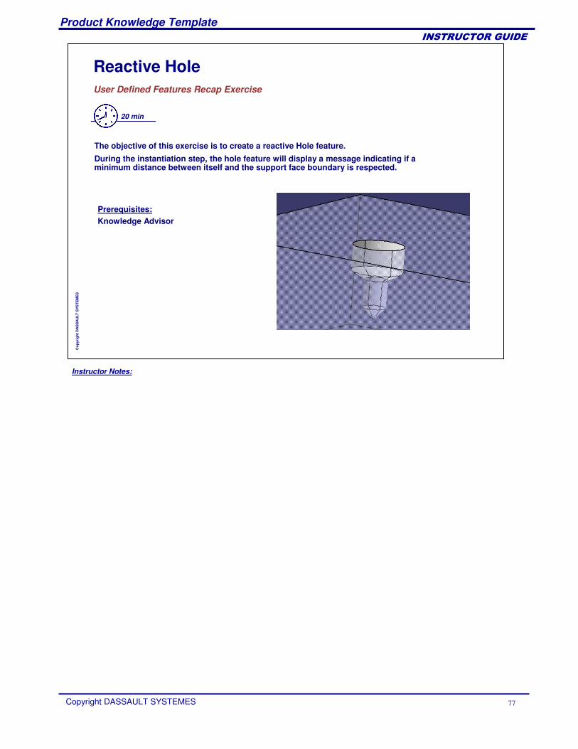
Reactive HoleUser Defined Features Recap Exercise
20 min
The objective of this exercise is to create a reactive Hole feature. During the instantiation step, the hole feature will display a message indicating if a minimum distance between itself and the support face boundary is respected.
Prerequisites:Knowledge Advisor
Instructor Notes:
Product Knowledge Template
Copyright DASSAULT SYSTEMES 78
��������������
Cop
yrig
ht D
AS
SA
ULT
SYS
TEM
ES
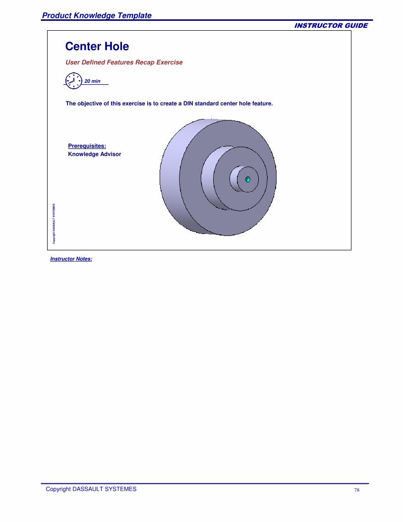
Center HoleUser Defined Features Recap Exercise
20 min
The objective of this exercise is to create a DIN standard center hole feature.
Prerequisites:Knowledge Advisor
Instructor Notes:
Product Knowledge Template
Copyright DASSAULT SYSTEMES 79
��������������
Cop
yrig
ht D
AS
SA
ULT
SYS
TEM
ES
Creating and Using Part and Assembly Templates
Presentation of Document TemplatesCreating a Document TemplateSaving a Document TemplateInstantiating a Document TemplateDocument Templates Recap Exercises
Instructor Notes:
Product Knowledge Template
Copyright DASSAULT SYSTEMES 80
��������������
Cop
yrig
ht D
AS
SA
ULT
SYS
TEM
ES
Presentation of Document TemplatesYou will learn about the benefits of Document Templates and their differences with respect to PowerCopies and User Defined Features.
Instructor Notes:
Product Knowledge Template
Copyright DASSAULT SYSTEMES 81
��������������
Cop
yrig
ht D
AS
SA
ULT
SYS
TEM
ES
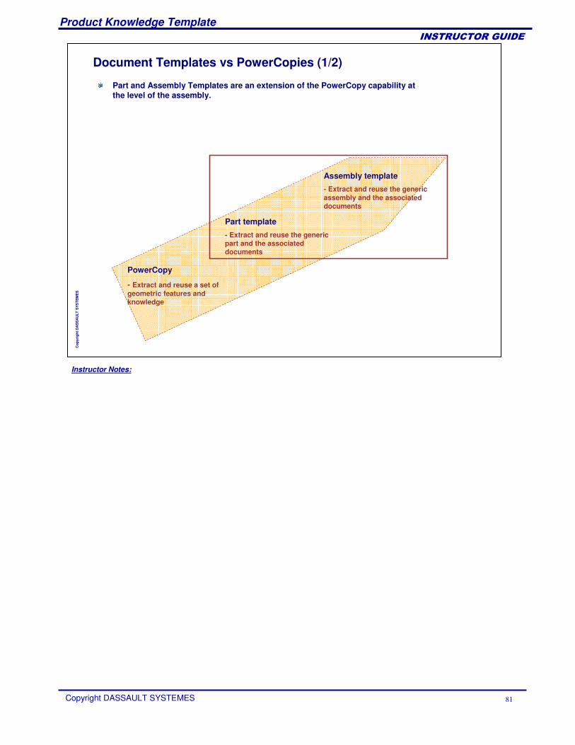
Document Templates vs PowerCopies (1/2)
PowerCopy
- Extract and reuse a set of geometric features and knowledge
Part template
- Extract and reuse the genericpart and the associateddocuments
Assembly template
- Extract and reuse the genericassembly and the associateddocuments
Part and Assembly Templates are an extension of the PowerCopy capability at the level of the assembly.
Instructor Notes:
Product Knowledge Template
Copyright DASSAULT SYSTEMES 82
��������������
Cop
yrig
ht D
AS
SA
ULT
SYS
TEM
ES
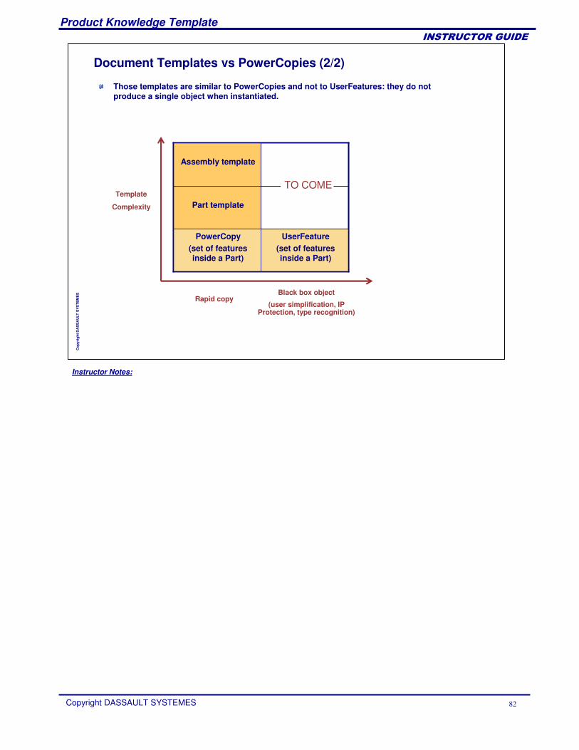
Document Templates vs PowerCopies (2/2)
User Feature(set of featuresinside a Part)
PowerCopy (set of featuresinside a Part)
Part template
Assemblytemplate
Template
Complexity
Black box object
(user simplification, IP Protection, type recognition)
Rapid copy
UserFeature(set of featuresinside a Part)
PowerCopy (set of featuresinside a Part)
Part template
Assembly template
TO COME
Those templates are similar to PowerCopies and not to UserFeatures: they do not produce a single object when instantiated.
Instructor Notes:
Product Knowledge Template
Copyright DASSAULT SYSTEMES 83
��������������
Cop
yrig
ht D
AS
SA
ULT
SYS
TEM
ES
What is a Part Template?A Part created in CATIA may contain user parameters and geometry data. It is not a contextual part. The user can create a part template that references that part. This template is a feature that is created in the CATPart document itself (very similar to the PowerCopy definition) and stored in a catalog. Several part templates may be defined in the same CATPart document.
To create a Part Template, the user: Selects parameters and geometry data that will be considered as the template inputs (he can assign a role and a comment to each input). Publishes some internal parameters (name and comment). The part number is automatically published. Gives a name, comment, URL, and icon to this template.
Once the template is created, the user stores it in a catalog and uses it in another context. In product structure context, the part is inserted as a component of the current product.
Instructor Notes:
Product Knowledge Template
Copyright DASSAULT SYSTEMES 84
��������������
Cop
yrig
ht D
AS
SA
ULT
SYS
TEM
ES
What is an Assembly Template?
A user creates an Assembly interactively. Then, he wants to create an Assembly Template that references the root product of this assembly.
To create an assembly template, the user:Selects parameters and geometry data that will be considered as the template inputs (he can assign a name to each input). Publishes some internal parameters (name and comment). Chooses if:� The part numbers of replicated components are automatically published� For each part or each sub-assembly this sub-component will be replicated at
instantiation, or if only a reference to this sub-component will be created (a standard component)
� He wants to select external documents (Drawings / Analysis) that references elements of the product structure. Those elements will be replicated at instantiation
Assigns a name, comment, URL and icon to this template.
Once this template is created, the user stores it in a catalog and uses it in another context.
The template definition is a feature located in the CATProduct document itself. Several assembly templates may be defined in the same CATProduct document.
Instructor Notes:
Product Knowledge Template
Copyright DASSAULT SYSTEMES 85
��������������
Cop
yrig
ht D
AS
SA
ULT
SYS
TEM
ES
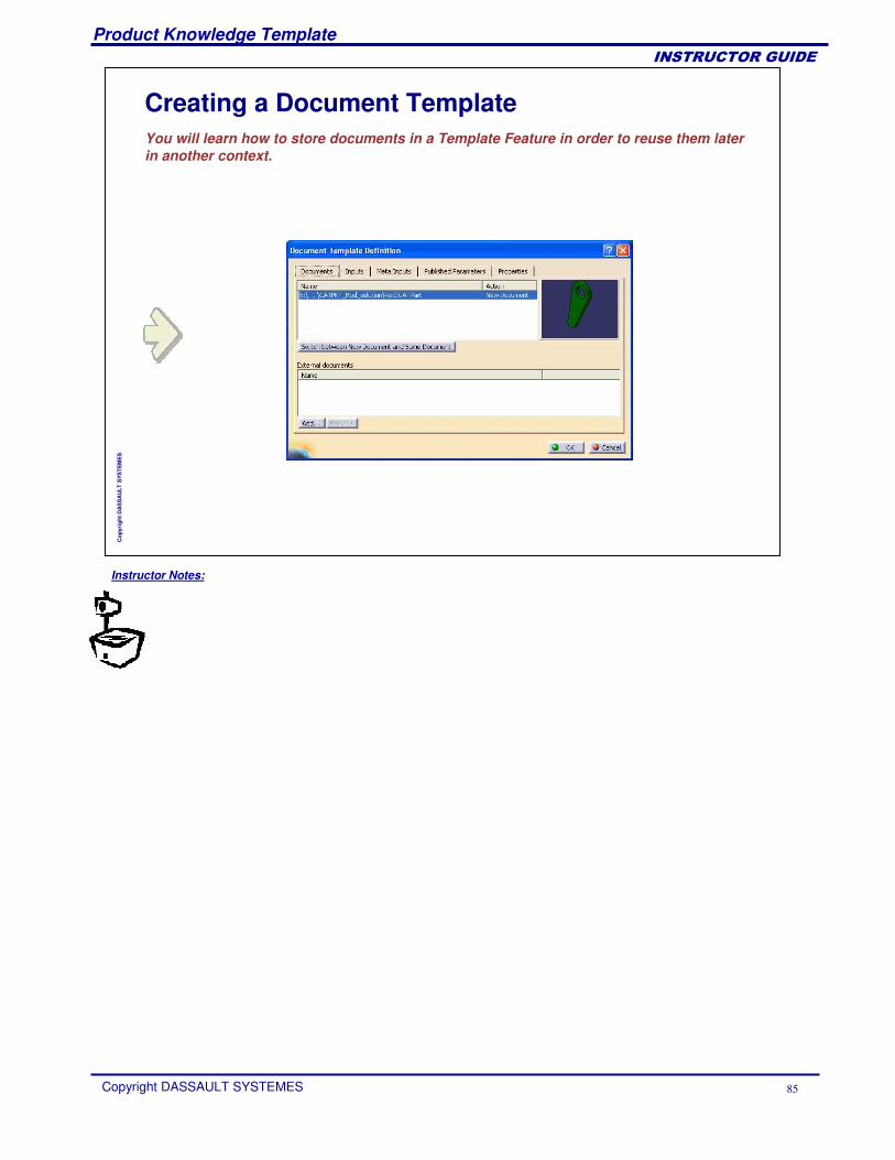
Creating a Document TemplateYou will learn how to store documents in a Template Feature in order to reuse them later in another context.
Instructor Notes:
Product Knowledge Template
Copyright DASSAULT SYSTEMES 86
��������������
Cop
yrig
ht D
AS
SA
ULT
SYS
TEM
ES
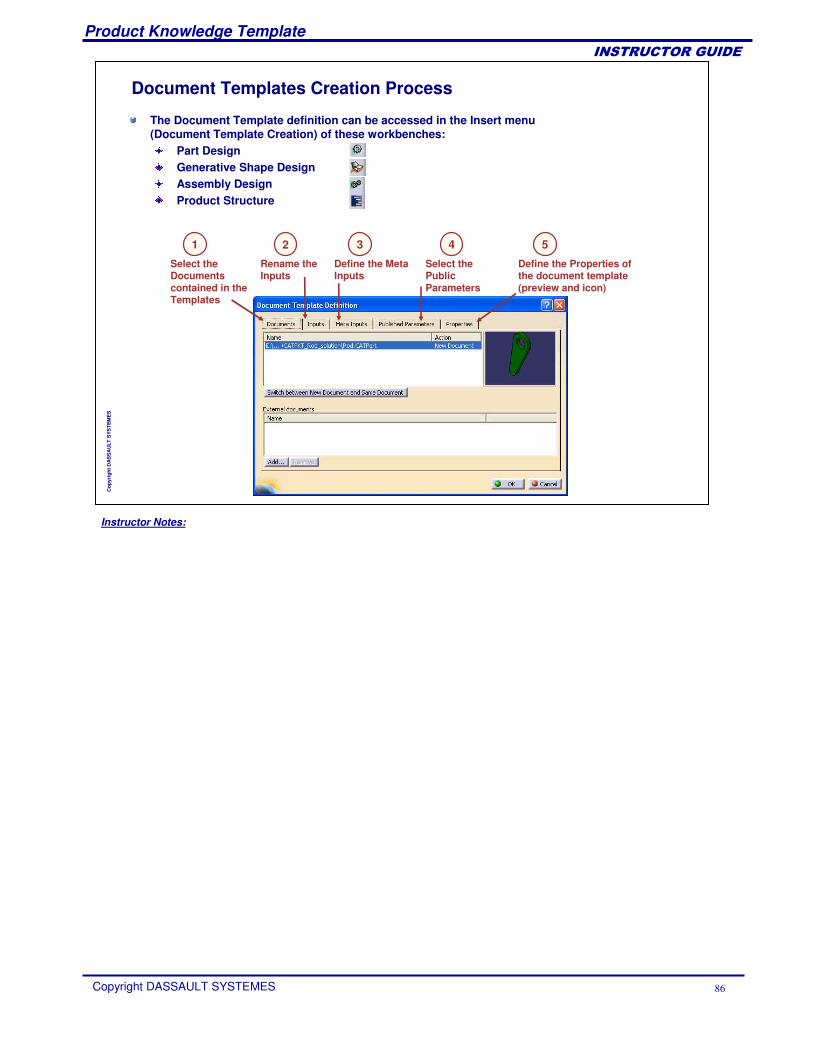
The Document Template definition can be accessed in the Insert menu (Document Template Creation) of these workbenches:
Part DesignGenerative Shape DesignAssembly DesignProduct Structure
Document Templates Creation Process
Select the Documents contained in the Templates
Rename the Inputs
Define the Meta Inputs
Select the Public Parameters
Define the Properties of the document template (preview and icon)
1 2 3 54
Instructor Notes:
Product Knowledge Template
Copyright DASSAULT SYSTEMES 87
��������������
Cop
yrig
ht D
AS
SA
ULT
SYS
TEM
ES
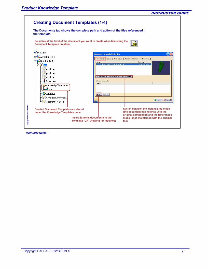
Creating Document Templates (1/4)
Created Document Templates are storedunder the Knowledge Templates node
Be active at the level of the document you want to create when launching the Document Template creation.
The Documents tab shows the complete path and action of the files referenced in the template.
Switch between the Instanciated mode (the document has no links with the original component) and the Referencedmode (links maintained with the original file)
Insert External documents to the Template (CATDrawing for instance)
Instructor Notes:
Product Knowledge Template
Copyright DASSAULT SYSTEMES 88
��������������
Cop
yrig
ht D
AS
SA
ULT
SYS
TEM
ES
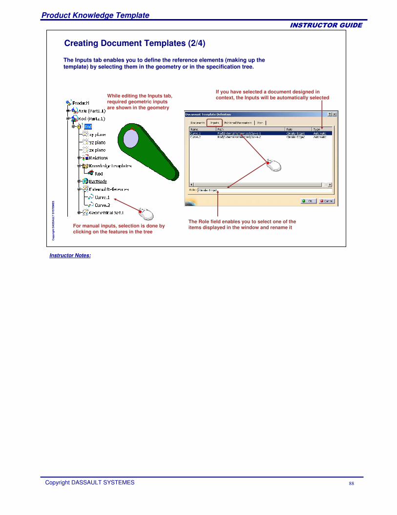
Creating Document Templates (2/4)
If you have selected a document designed in context, the Inputs will be automatically selected
The Role field enables you to select one of the items displayed in the window and rename it
While editing the Inputs tab, required geometric inputs are shown in the geometry
For manual inputs, selection is done by clicking on the features in the tree
The Inputs tab enables you to define the reference elements (making up the template) by selecting them in the geometry or in the specification tree.
Instructor Notes:
Product Knowledge Template
Copyright DASSAULT SYSTEMES 89
��������������
Cop
yrig
ht D
AS
SA
ULT
SYS
TEM
ES
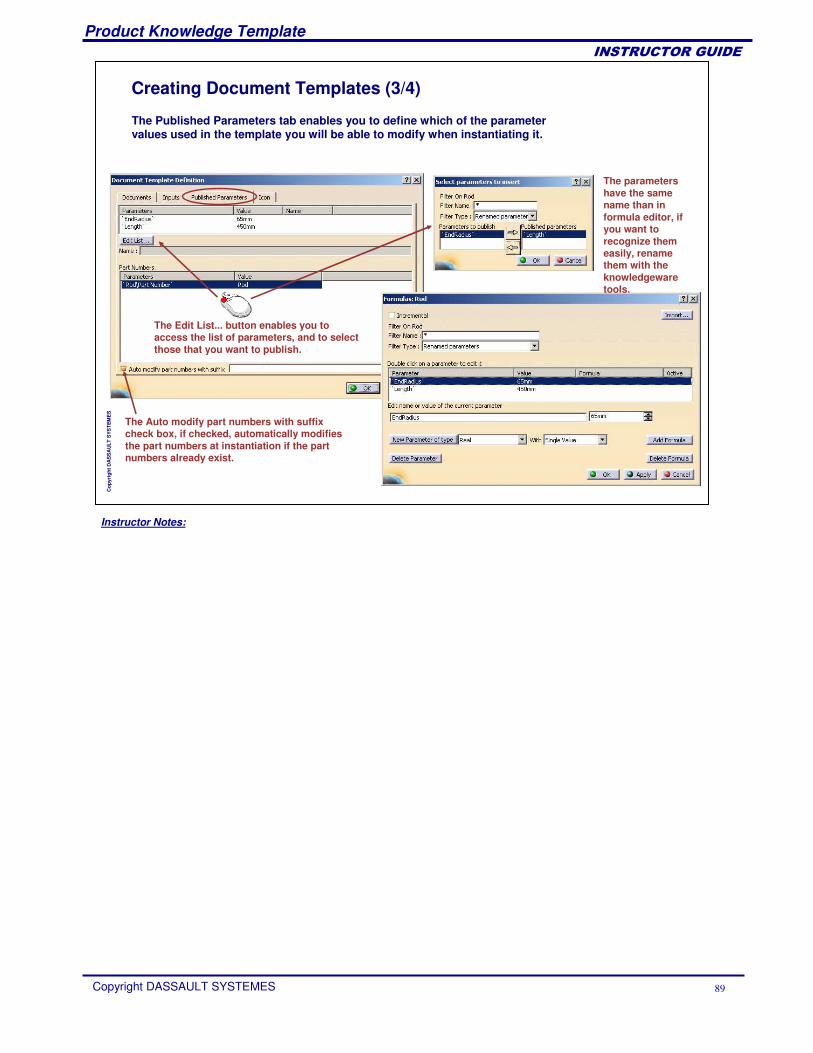
Creating Document Templates (3/4)
The parametershave the samename than in formula editor, if you want to recognize themeasily, renamethem with the knowledgewaretools.
The Auto modify part numbers with suffix check box, if checked, automatically modifies the part numbers at instantiation if the part numbers already exist.
The Edit List... button enables you to access the list of parameters, and to select those that you want to publish.
The Published Parameters tab enables you to define which of the parameter values used in the template you will be able to modify when instantiating it.
Instructor Notes:
Product Knowledge Template
Copyright DASSAULT SYSTEMES 90
��������������
Cop
yrig
ht D
AS
SA
ULT
SYS
TEM
ES
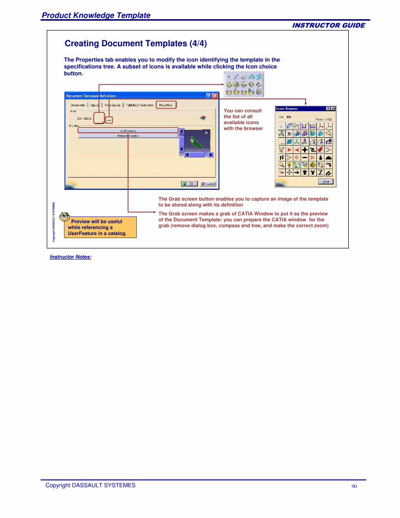
Creating Document Templates (4/4)
The Grab screen button enables you to capture an image of the template to be stored along with its definition
The Grab screen makes a grab of CATIA Window to put it as the previewof the Document Template: you can prepare the CATIA window for the grab (remove dialog box, compass and tree, and make the correct zoom)
You can consultthe list of all available iconswith the browser
The Properties tab enables you to modify the icon identifying the template in the specifications tree. A subset of icons is available while clicking the Icon choice button.
Preview will be useful while referencing a UserFeature in a catalog.
Instructor Notes:
Product Knowledge Template
Copyright DASSAULT SYSTEMES 91
��������������
Cop
yrig
ht D
AS
SA
ULT
SYS
TEM
ES
Saving a Document TemplateYou will learn how to store a Document Template in a catalog in order to share it with other users or to reuse it later in another context.
Instructor Notes:
Product Knowledge Template
Copyright DASSAULT SYSTEMES 92
��������������
Cop
yrig
ht D
AS
SA
ULT
SYS
TEM
ES
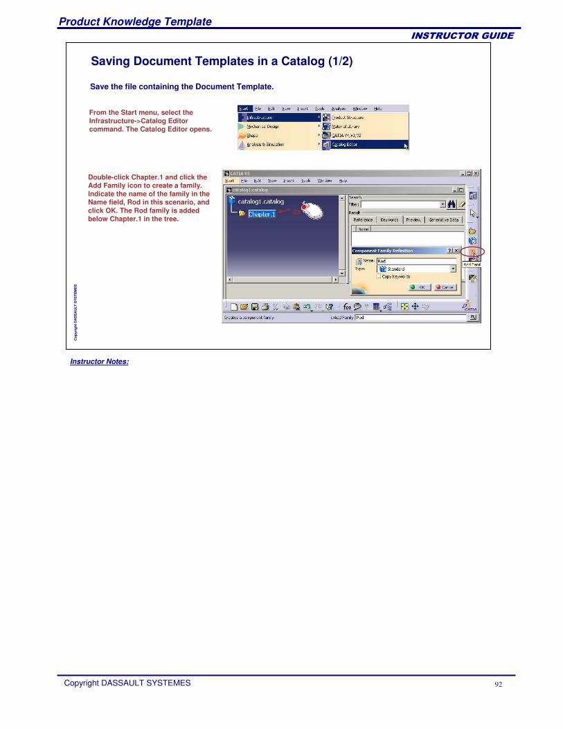
Saving Document Templates in a Catalog (1/2)
From the Start menu, select the Infrastructure->Catalog Editor command. The Catalog Editor opens.
Double-click Chapter.1 and click the Add Family icon to create a family. Indicate the name of the family in the Name field, Rod in this scenario, and click OK. The Rod family is added below Chapter.1 in the tree.
2x
Save the file containing the Document Template.
Instructor Notes:
Product Knowledge Template
Copyright DASSAULT SYSTEMES 93
��������������
Cop
yrig
ht D
AS
SA
ULT
SYS
TEM
ES
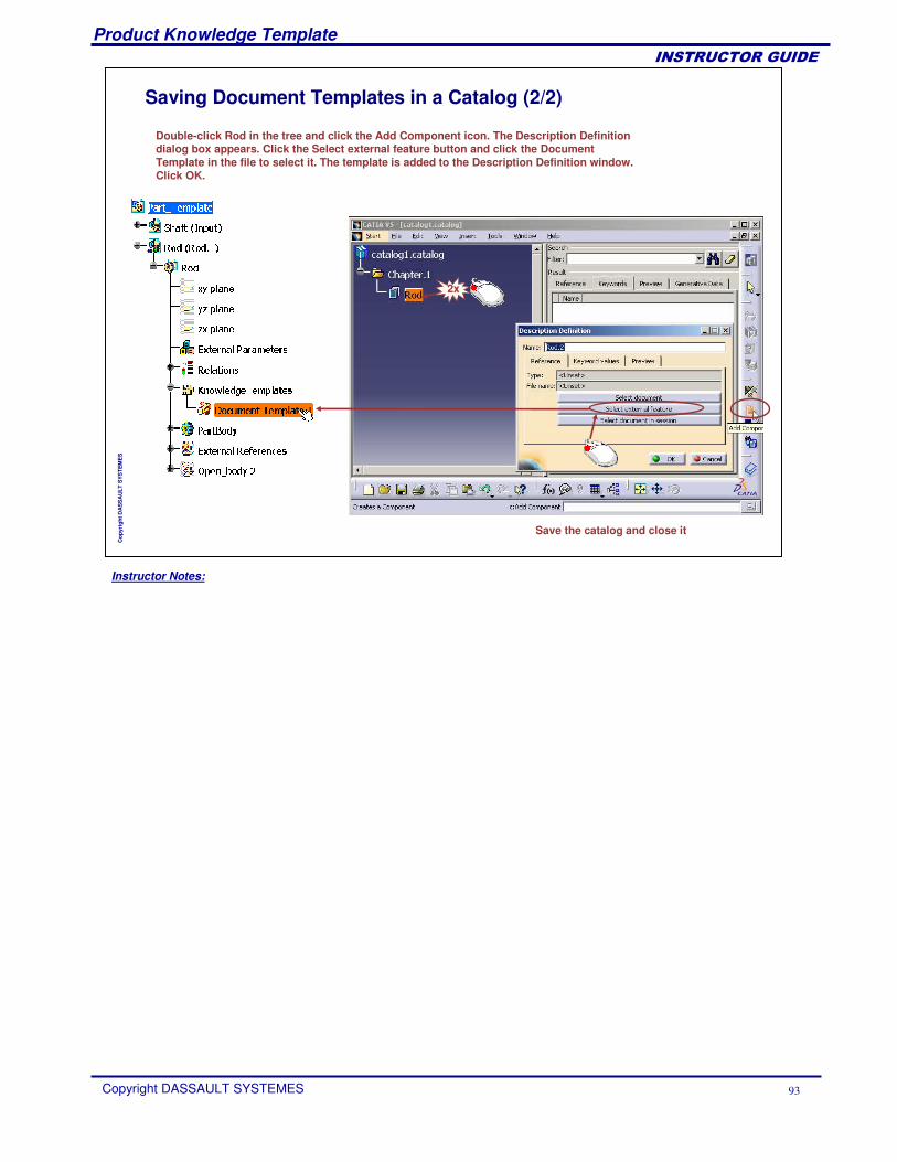
Saving Document Templates in a Catalog (2/2)
Double-click Rod in the tree and click the Add Component icon. The Description Definition dialog box appears. Click the Select external feature button and click the Document Template in the file to select it. The template is added to the Description Definition window. Click OK.
Save the catalog and close it
2x
Instructor Notes:
Product Knowledge Template
Copyright DASSAULT SYSTEMES 94
��������������
Cop
yrig
ht D
AS
SA
ULT
SYS
TEM
ES
Instantiating a Document TemplateYou will learn how to import a Document Template in a new context and how to adapt it to this context.
Instructor Notes:
Product Knowledge Template
Copyright DASSAULT SYSTEMES 95
��������������
Cop
yrig
ht D
AS
SA
ULT
SYS
TEM
ES
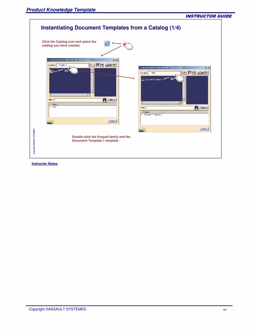
Instantiating Document Templates from a Catalog (1/4)
Click the Catalog icon and select the catalog you have created.
2x
Double-click the Keypad family and the Document Template.1 template
2x
Instructor Notes:
Product Knowledge Template
Copyright DASSAULT SYSTEMES 96
��������������
Cop
yrig
ht D
AS
SA
ULT
SYS
TEM
ES
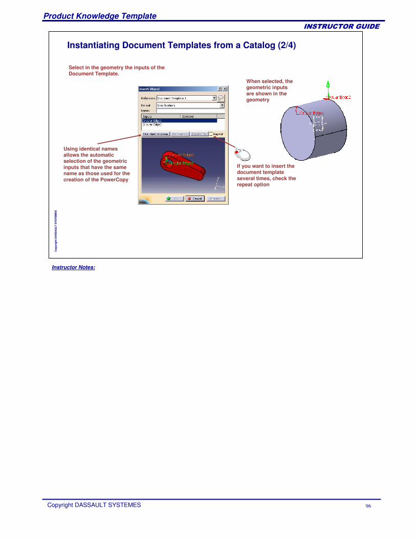
Instantiating Document Templates from a Catalog (2/4)
Select in the geometry the inputs of the Document Template.
When selected, the geometric inputs are shown in the geometry
Using identical namesallows the automaticselection of the geometricinputs that have the samename as those used for the creation of the PowerCopy
If you want to insert the document templateseveral times, check the repeat option
Instructor Notes:
Product Knowledge Template
Copyright DASSAULT SYSTEMES 97
��������������
Cop
yrig
ht D
AS
SA
ULT
SYS
TEM
ES
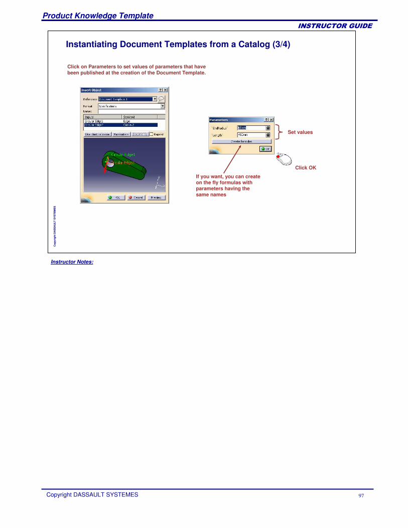
Instantiating Document Templates from a Catalog (3/4)
Click on Parameters to set values of parameters that have been published at the creation of the Document Template.
Set values
Click OK
If you want, you can createon the fly formulas withparameters having the same names
Instructor Notes:
Product Knowledge Template
Copyright DASSAULT SYSTEMES 98
��������������
Cop
yrig
ht D
AS
SA
ULT
SYS
TEM
ES
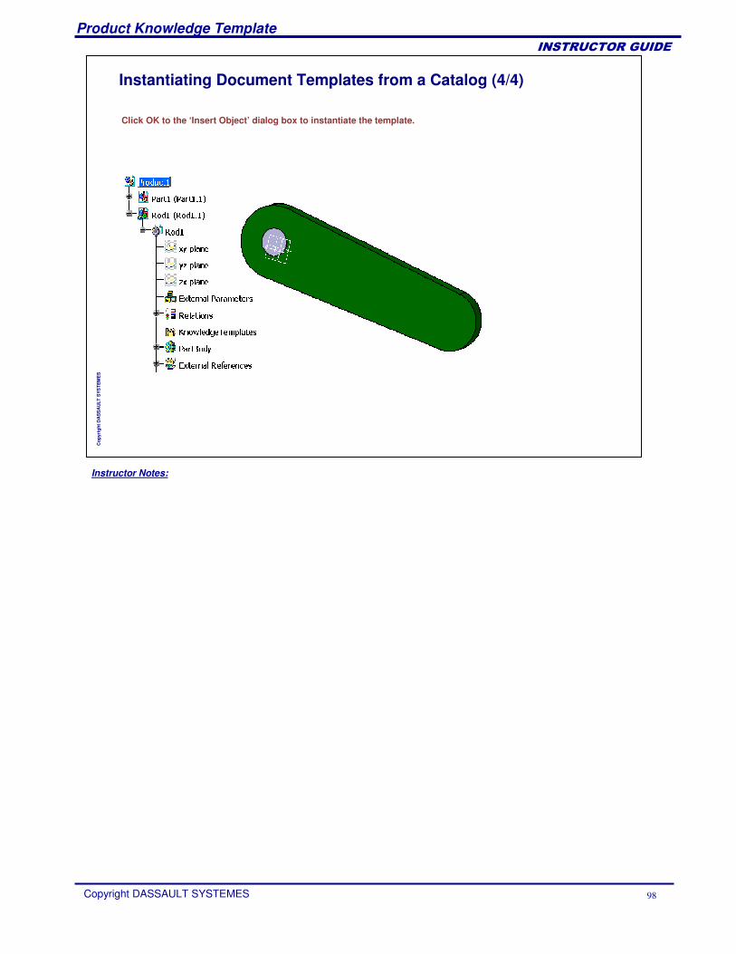
Instantiating Document Templates from a Catalog (4/4)
Click OK to the ‘Insert Object’ dialog box to instantiate the template.
Instructor Notes:
Product Knowledge Template
Copyright DASSAULT SYSTEMES 99
��������������
Cop
yrig
ht D
AS
SA
ULT
SYS
TEM
ES
Document Templates Recap ExercisesYou will practice Document Templates through three exercises:
Rod Part Template Recap ExerciseSupport Part Template Recap ExerciseTow Hook Assembly Template Recap Exercise
Instructor Notes:
Product Knowledge Template
Copyright DASSAULT SYSTEMES 100
��������������
Cop
yrig
ht D
AS
SA
ULT
SYS
TEM
ES
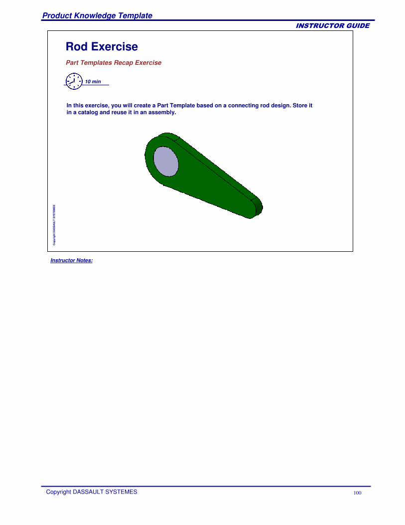
Rod ExercisePart Templates Recap Exercise
10 min
In this exercise, you will create a Part Template based on a connecting rod design. Store itin a catalog and reuse it in an assembly.
Instructor Notes:
Product Knowledge Template
Copyright DASSAULT SYSTEMES 101
��������������
Cop
yrig
ht D
AS
SA
ULT
SYS
TEM
ES
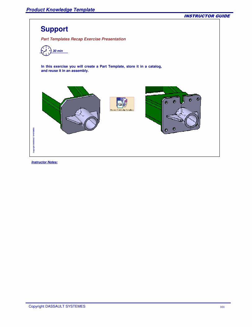
SupportPart Templates Recap Exercise Presentation
30 min
In this exercise you will create a Part Template, store it in a catalog, and reuse it in an assembly.
Instructor Notes:
Product Knowledge Template
Copyright DASSAULT SYSTEMES 102
��������������
Cop
yrig
ht D
AS
SA
ULT
SYS
TEM
ES
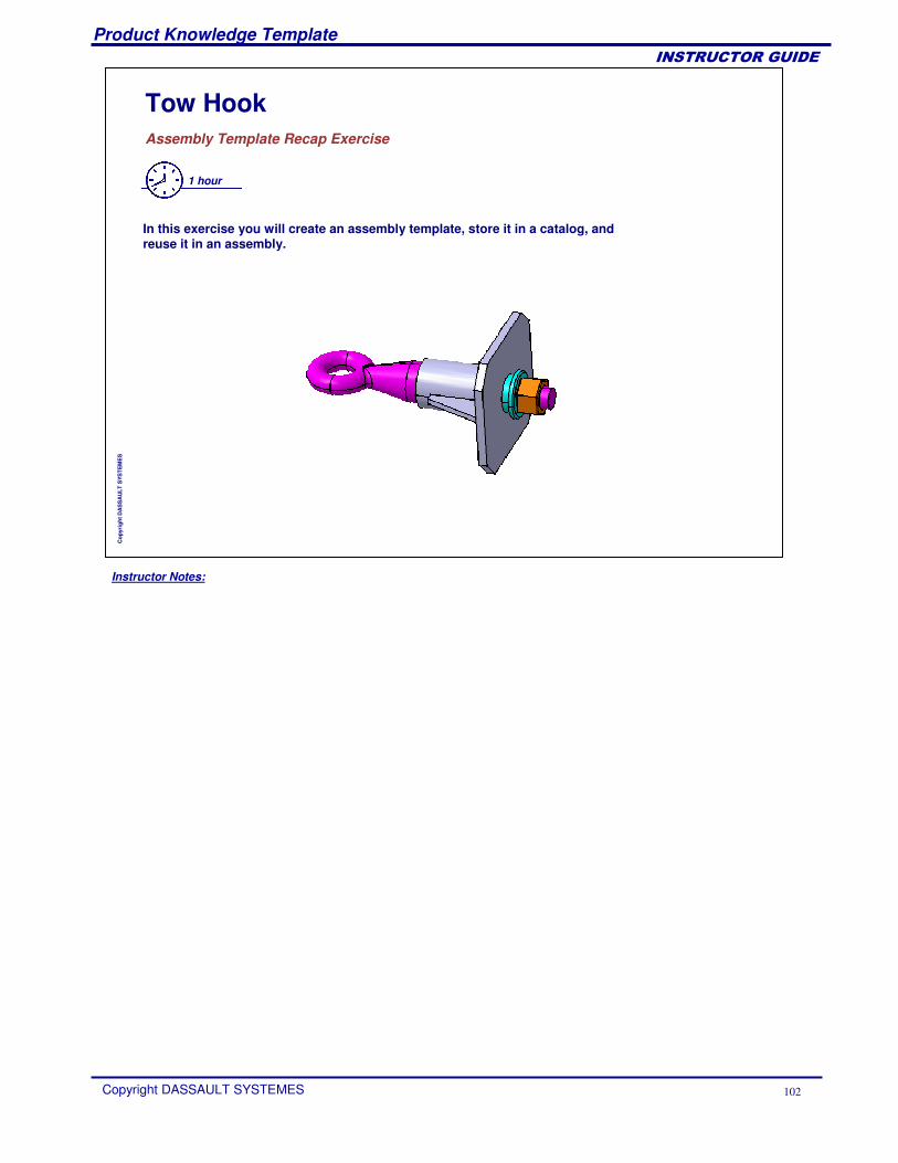
Tow HookAssembly Template Recap Exercise
1 hour
In this exercise you will create an assembly template, store it in a catalog, and reuse it in an assembly.
Instructor Notes:
Product Knowledge Template
Copyright DASSAULT SYSTEMES 103
��������������
Cop
yrig
ht D
AS
SA
ULT
SYS
TEM
ES
Managing Standard ComponentsYou will learn how to deal with standard components in Document Templates.
Instructor Notes:
Product Knowledge Template
Copyright DASSAULT SYSTEMES 104
��������������
Cop
yrig
ht D
AS
SA
ULT
SYS
TEM
ES
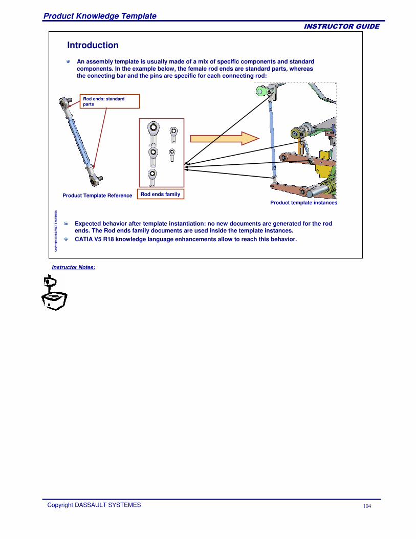
Introduction
An assembly template is usually made of a mix of specific components and standard components. In the example below, the female rod ends are standard parts, whereas the conecting bar and the pins are specific for each connecting rod:
Rod ends: standard parts
Product Template ReferenceProduct template instances
Rod ends family
Expected behavior after template instantiation: no new documents are generated for the rod ends. The Rod ends family documents are used inside the template instances.CATIA V5 R18 knowledge language enhancements allow to reach this behavior.
Instructor Notes:
Product Knowledge Template
Copyright DASSAULT SYSTEMES 105
��������������
Cop
yrig
ht D
AS
SA
ULT
SYS
TEM
ES
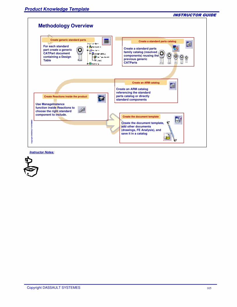
Methodology Overview
Create a standard parts catalog
Create a standard parts family catalog (resolved components) reusing the previous generic CATParts
Create generic standard parts
For each standard part create a generic CATPart document containing a Design Table
Create an ARM catalog
Create an ARM catalog referencing the standard parts catalog or directly standard components
Use ManageInstancefunction inside Reactions to choose the right standard component to include.
Create Reactions inside the product
Create the document template
Create the document template, add other documents (drawings, FE Analysis), and save it in a catalog
Instructor Notes:
Product Knowledge Template
Copyright DASSAULT SYSTEMES 106
��������������
Cop
yrig
ht D
AS
SA
ULT
SYS
TEM
ES
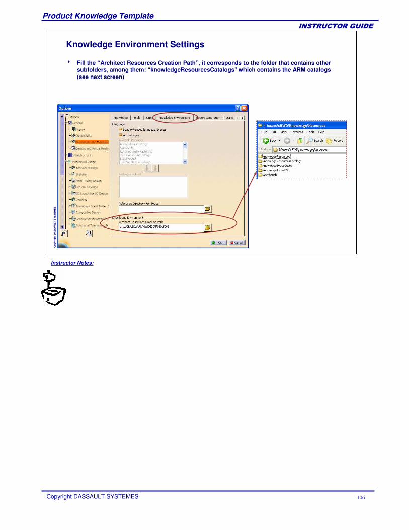
Knowledge Environment Settings
� Fill the “Architect Resources Creation Path”, it corresponds to the folder that contains other subfolders, among them: “knowledgeResourcesCatalogs” which contains the ARM catalogs (see next screen)
Instructor Notes:
Product Knowledge Template
Copyright DASSAULT SYSTEMES 107
��������������
Cop
yrig
ht D
AS
SA
ULT
SYS
TEM
ES
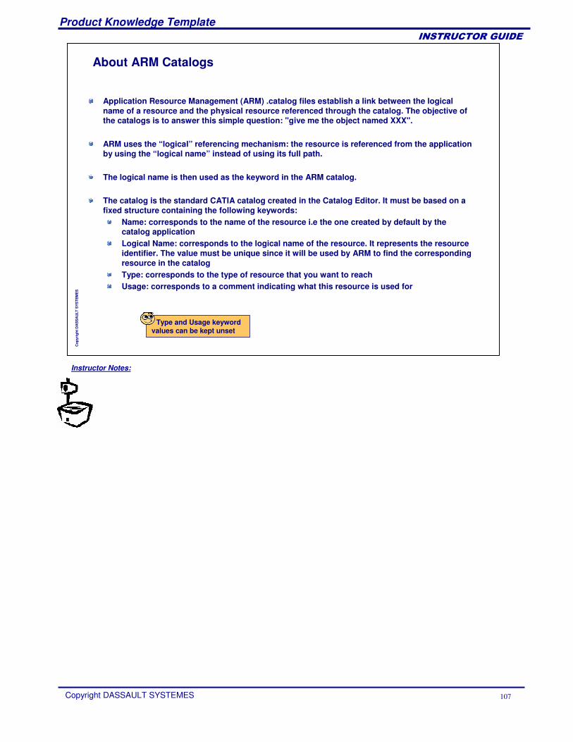
Type and Usage keyword values can be kept unset
About ARM Catalogs
Application Resource Management (ARM) .catalog files establish a link between the logical name of a resource and the physical resource referenced through the catalog. The objective of the catalogs is to answer this simple question: "give me the object named XXX".
ARM uses the “logical” referencing mechanism: the resource is referenced from the application by using the “logical name” instead of using its full path.
The logical name is then used as the keyword in the ARM catalog.
The catalog is the standard CATIA catalog created in the Catalog Editor. It must be based on a fixed structure containing the following keywords:
Name: corresponds to the name of the resource i.e the one created by default by the catalog applicationLogical Name: corresponds to the logical name of the resource. It represents the resource identifier. The value must be unique since it will be used by ARM to find the corresponding resource in the catalog Type: corresponds to the type of resource that you want to reachUsage: corresponds to a comment indicating what this resource is used for
Instructor Notes:
Product Knowledge Template
Copyright DASSAULT SYSTEMES 108
��������������
Cop
yrig
ht D
AS
SA
ULT
SYS
TEM
ES
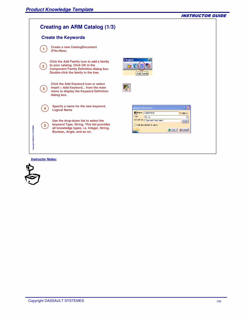
Create a new CatalogDocument(File>New).
Click the Add Family icon to add a family to your catalog. Click OK in the Component Family Definition dialog box. Double-click the family in the tree.
Click the Add Keyword icon or select Insert > Add Keyword... from the main menu to display the Keyword Definition dialog box.
Use the drop-down list to select the keyword Type, String. This list provides all knowledge types, i.e. Integer, String, Boolean, Angle, and so on.
Specify a name for the new keyword, Logical Name
1
2
5
4
3
Create the Keywords
Creating an ARM Catalog (1/3)
Instructor Notes:
Product Knowledge Template
Copyright DASSAULT SYSTEMES 109
��������������
Cop
yrig
ht D
AS
SA
ULT
SYS
TEM
ES
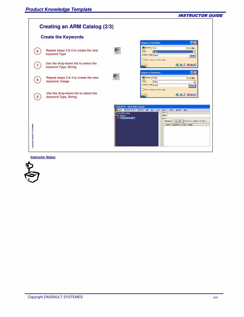
Use the drop-down list to select the keyword Type, String
Repeat steps 3 & 4 to create the new keyword Type
7
6
Repeat steps 3 & 4 to create the new keyword, Usage
Use the drop-down list to select the keyword Type, String
8
9
Create the Keywords
Creating an ARM Catalog (2/3)
Instructor Notes:
Product Knowledge Template
Copyright DASSAULT SYSTEMES 110
��������������
Cop
yrig
ht D
AS
SA
ULT
SYS
TEM
ES
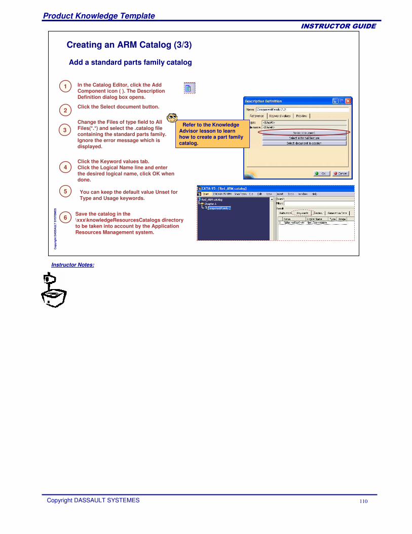
Click the Select document button.
In the Catalog Editor, click the Add Component icon ( ). The Description Definition dialog box opens.
2
1
Click the Keyword values tab. Click the Logical Name line and enter the desired logical name, click OK when done.
3
Add a standard parts family catalog
Refer to the Knowledge Advisor lesson to learn how to create a part family catalog.
Change the Files of type field to All Files(*.*) and select the .catalog file containing the standard parts family. Ignore the error message which is displayed.
4
5 You can keep the default value Unset for Type and Usage keywords.
Save the catalog in the \xxx\knowledgeResourcesCatalogs directory to be taken into account by the Application Resources Management system.
6
Creating an ARM Catalog (3/3)
Instructor Notes:
Product Knowledge Template
Copyright DASSAULT SYSTEMES 111
��������������
Cop
yrig
ht D
AS
SA
ULT
SYS
TEM
ES
The Knowledgeware language provides the ManageInstance and the RemoveInstance functions to address three major cases:
Case 1: need to switch between different standard componentsCase 2: need to switch on/off a standard component Case 3: need to search for the right element inside a standard parts family
SyntaxProduct->ManageInstance(arm : String, chapterName : String, query : String, instanceName : String): Product
ARM: Application Resource Management string. It is composed of two parts separated by “|”: <catalogName>|<value of the keyword “Logical Name” of the catalog description>. The catalog description has to reference either a CATPArt document or a CATProduct document (case 1& 2) or a catalog document (case 3).Chaptername: This argument is only used in case 2. In this case the ARM resource is a catalog document, and if the chapter name is specified, the system looks for the catalog chapter of this name.Query: This argument is only used in case 2. in this case, the query is used to retrieve the part family elements that fit this query, either in a specific chapter i.e. the chapterNameargument is filled, or in the whole catalog. InstanceName: The ManageInstance method either creates or replaces a product instance. This argument is used to retrieve the existing instance, if any. It is also used to rename the created instance.
Product->RemoveInstance(instanceName : String
Choosing the Right Standard Component (1/5)
Instructor Notes:
Product Knowledge Template
Copyright DASSAULT SYSTEMES 112
��������������
Cop
yrig
ht D
AS
SA
ULT
SYS
TEM
ES
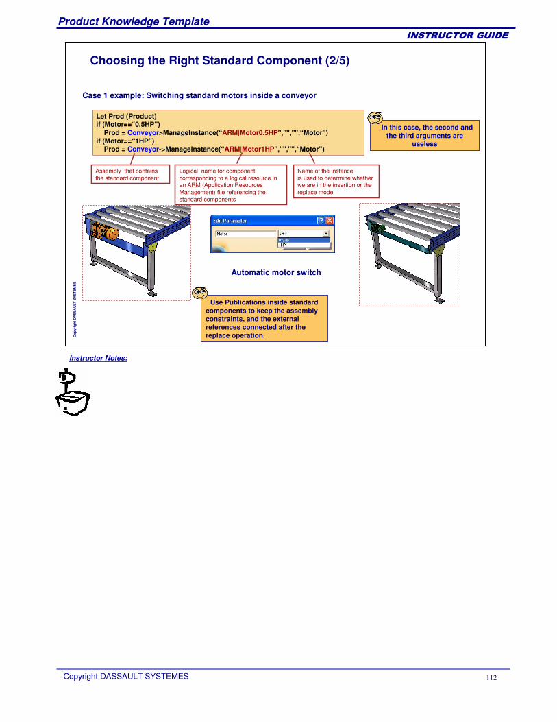
Let Prod (Product)if (Motor==“0.5HP”)
Prod = Conveyor>ManageInstance(“ARM|Motor0.5HP","","",“Motor")if (Motor==“1HP”)
Prod = Conveyor->ManageInstance(“ARM|Motor1HP","","",“Motor")
Case 1 example: Switching standard motors inside a conveyor
Logical name for component corresponding to a logical resource in an ARM (Application Resources Management) file referencing the standard components
Assembly that contains the standard component
Name of the instanceis used to determine whether we are in the insertion or the replace mode
Use Publications inside standard components to keep the assembly constraints, and the external references connected after the replace operation.
In this case, the second and the third arguments are
useless
Automatic motor switch
Choosing the Right Standard Component (2/5)
Instructor Notes:
Product Knowledge Template
Copyright DASSAULT SYSTEMES 113
��������������
Cop
yrig
ht D
AS
SA
ULT
SYS
TEM
ES
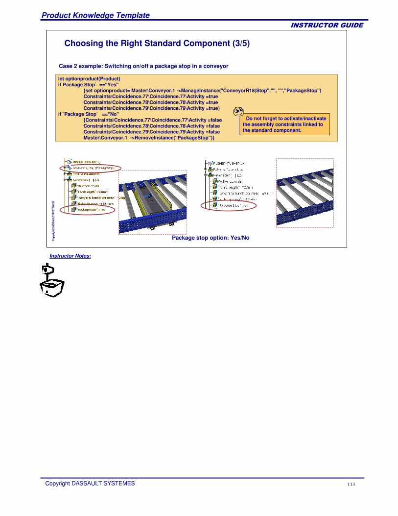
let optionproduct(Product)if P̀ackage Stop ̀ =="Yes"
{set optionproduct= Master\Conveyor.1 ->ManageInstance("ConveyorR18|Stop","", "","PackageStop") Constraints\Coincidence.77\Coincidence.77\Activity =trueConstraints\Coincidence.78\Coincidence.78\Activity =trueConstraints\Coincidence.79\Coincidence.79\Activity =true}
if P̀ackage Stop ̀ =="No"{Constraints\Coincidence.77\Coincidence.77\Activity =falseConstraints\Coincidence.78\Coincidence.78\Activity =falseConstraints\Coincidence.79\Coincidence.79\Activity =falseMaster\Conveyor.1 ->RemoveInstance("PackageStop“)}
Case 2 example: Switching on/off a package stop in a conveyor
Do not forget to activate/inactivate the assembly constraints linked to the standard component.
Package stop option: Yes/No
Choosing the Right Standard Component (3/5)
Instructor Notes:
Product Knowledge Template
Copyright DASSAULT SYSTEMES 114
��������������
Cop
yrig
ht D
AS
SA
ULT
SYS
TEM
ES
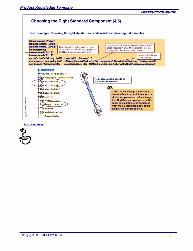
Case 3 example: Choosing the right standard rod ends inside a connecting rod assembly
Add the knowledge instructions inside a Reaction, which reacts to a skeleton’s parameter value change, End Rod Diameter parameter in this case. This parameter is computed from the selected geometry at the template instantiation step.
������������������� ��������� ��������� ��������� ������ �� ������� ������� ������� ����������������� ������ ���������������� ������ ���������������� ������ ���������������� ������ ���������������� ������ ���������������� ������ ���������������� ������ ���������������� ������ ����������������������� ���� ������ ���� ������ ���� ������ ���� ��������������� ����� ������������� ����� ������������� ����� ������������� ����� ������������� ����� ������������� ����� ������������� ����� ������������� ����� �������� ������ ������ ������ ��������������� ���������������� ��� ����!� �� ��� ����!� �� ��� ����!� �� ��� ����!� �� �"�������"�������"�������"������####$���� ���� �� ��� !�����$���� ���� �� ��� !�����$���� ���� �� ��� !�����$���� ���� �� ��� !�������� ��������� ��������� ��������� ��������!% ���������� ��!�����!% ���������� ��!�����!% ���������� ��!�����!% ���������� ��!���&&&&'( ���)�������� ��*+ � ( ,���*% �� -�������.��-/� ��$��� ����.��� '( ���)�������� ��*+ � ( ,���*% �� -�������.��-/� ��$��� ����.��� '( ���)�������� ��*+ � ( ,���*% �� -�������.��-/� ��$��� ����.��� '( ���)�������� ��*+ � ( ,���*% �� -�������.��-/� ��$��� ����.��� �.�������� ����.�������� ����.�������� ����.�������� ������ ��������� ��������� ��������� �������!% ���������� ��!����!% ���������� ��!����!% ���������� ��!����!% ���������� ��!���&&&&'( ���)�������� ��*+ � ( ,���*% �� -�������.��-/� ��$��� ����.��� '( ���)�������� ��*+ � ( ,���*% �� -�������.��-/� ��$��� ����.��� '( ���)�������� ��*+ � ( ,���*% �� -�������.��-/� ��$��� ����.��� '( ���)�������� ��*+ � ( ,���*% �� -�������.��-/� ��$��� ����.��� �.�������� ����.�������� ����.�������� ����.�������� ���
Name of the chapter in the catalog
Logical name for the catalog corresponding to the logical resource in an ARM (Application Resources Management) file, referencing a catalog
Query to perform in the catalog: search for rod ends with a diameter (D) equal to End Rod Diameter parameter value
Rod ends: standard parts to be automatically replaced
Choosing the Right Standard Component (4/5)
Instructor Notes:
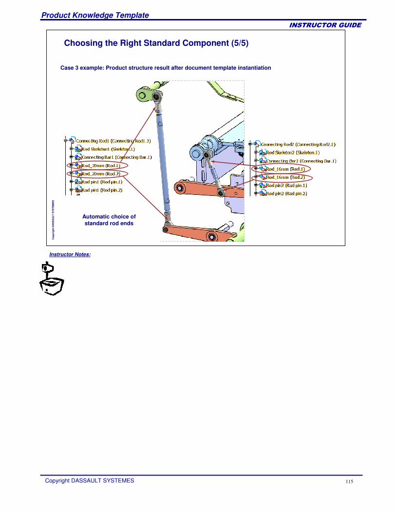
Product Knowledge Template
Copyright DASSAULT SYSTEMES 115
��������������
Cop
yrig
ht D
AS
SA
ULT
SYS
TEM
ES
Case 3 example: Product structure result after document template instantiation
Automatic choice of standard rod ends
Choosing the Right Standard Component (5/5)
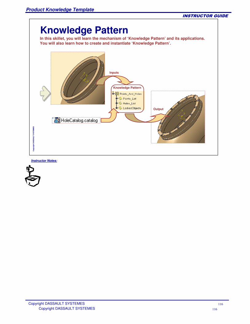
Instructor Notes:
Product Knowledge Template
Copyright DASSAULT SYSTEMES 116
��������������
Copyright DASSAULT SYSTEMES 116
Cop
yrig
ht D
AS
SA
ULT
SYS
TEM
ES
Knowledge PatternIn this skillet, you will learn the mechanism of ‘Knowledge Pattern’ and its applications. You will also learn how to create and instantiate ‘Knowledge Pattern’.
Knowledge Pattern
Inputs
Output
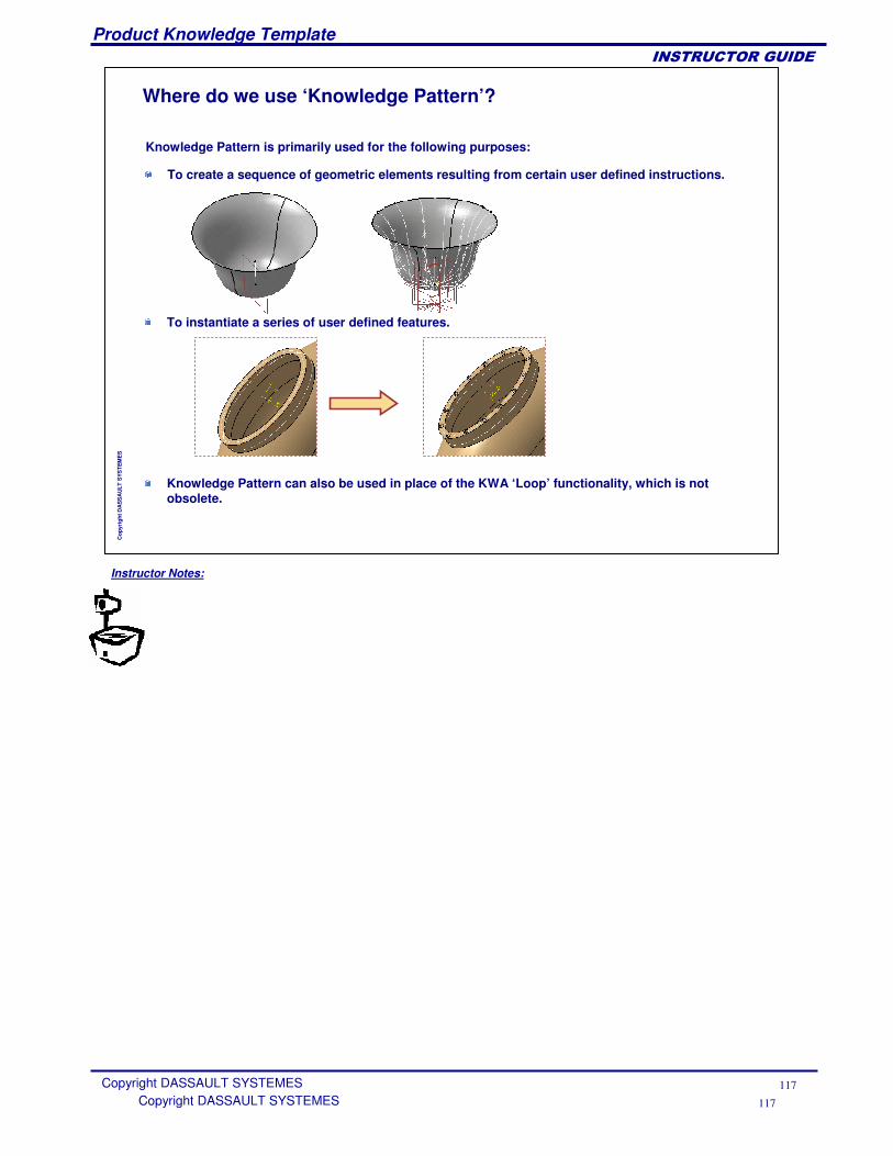
Instructor Notes:
Product Knowledge Template
Copyright DASSAULT SYSTEMES 117
��������������
Copyright DASSAULT SYSTEMES 117
Cop
yrig
ht D
AS
SA
ULT
SYS
TEM
ES
Where do we use ‘Knowledge Pattern’?
To create a sequence of geometric elements resulting from certain user defined instructions.
To instantiate a series of user defined features.
Knowledge Pattern is primarily used for the following purposes:
Knowledge Pattern can also be used in place of the KWA ‘Loop’ functionality, which is not obsolete.
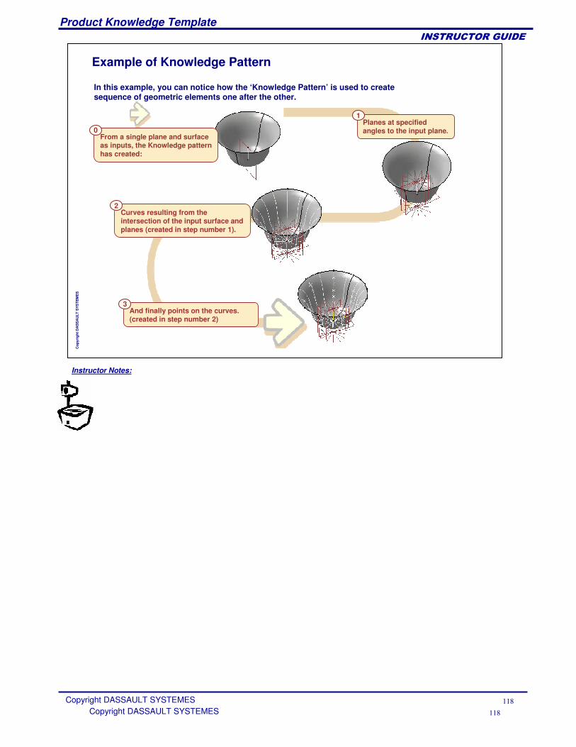
Instructor Notes:
Product Knowledge Template
Copyright DASSAULT SYSTEMES 118
��������������
Copyright DASSAULT SYSTEMES 118
Cop
yrig
ht D
AS
SA
ULT
SYS
TEM
ES
Example of Knowledge Pattern
In this example, you can notice how the ‘Knowledge Pattern’ is used to create sequence of geometric elements one after the other.
From a single plane and surface as inputs, the Knowledge pattern has created:
0Planes at specified angles to the input plane.
1
Curves resulting from the intersection of the input surface and planes (created in step number 1).
2
And finally points on the curves. (created in step number 2)
3
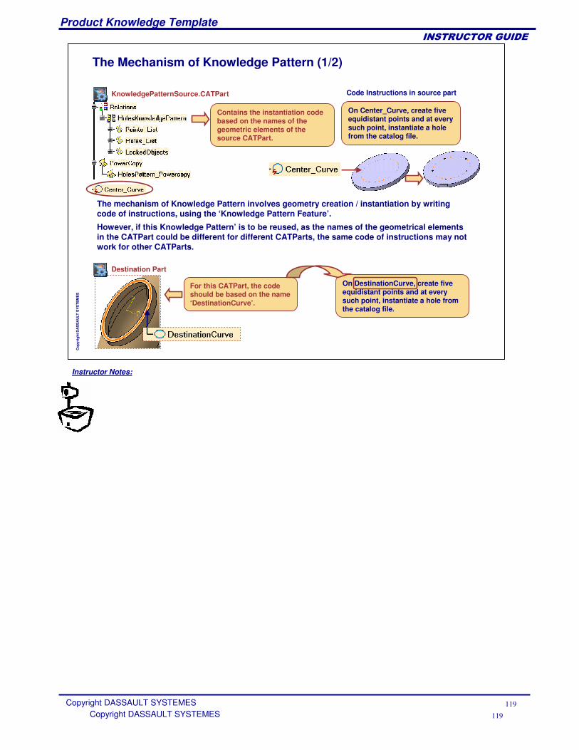
Instructor Notes:
Product Knowledge Template
Copyright DASSAULT SYSTEMES 119
��������������
Copyright DASSAULT SYSTEMES 119
Cop
yrig
ht D
AS
SA
ULT
SYS
TEM
ES
The Mechanism of Knowledge Pattern (1/2)
The mechanism of Knowledge Pattern involves geometry creation / instantiation by writing code of instructions, using the ‘Knowledge Pattern Feature’.
KnowledgePatternSource.CATPart
Contains the instantiation code based on the names of the geometric elements of the source CATPart.
Code Instructions in source part
On Center_Curve, create five equidistant points and at every such point, instantiate a hole from the catalog file.
However, if this Knowledge Pattern’ is to be reused, as the names of the geometrical elements in the CATPart could be different for different CATParts, the same code of instructions may not work for other CATParts.
For this CATPart, the code should be based on the name ‘DestinationCurve’.
On DestinationCurve, create five equidistant points and at every such point, instantiate a hole from the catalog file.
Destination Part
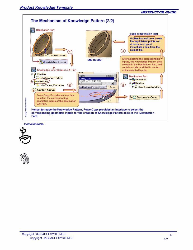
Instructor Notes:
Product Knowledge Template
Copyright DASSAULT SYSTEMES 120
��������������
Copyright DASSAULT SYSTEMES 120
Cop
yrig
ht D
AS
SA
ULT
SYS
TEM
ES
The Mechanism of Knowledge Pattern (2/2)
PowerCopy Provides an interface to select the corresponding geometric inputs of the destination CATPart.
KnowledgePatternSource.CATPart
Hence, to reuse the Knowledge Pattern, PowerCopy provides an interface to select the corresponding geometric inputs for the creation of Knowledge Pattern code in the ‘Destination Part’.
Destination Part
After selecting the corresponding inputs, the Knowledge Pattern gets created in the Destination Part, and contains code modified in context of the selected inputs.
Destination Part
On DestinationCurve, create five equidistant points and at every such point, instantiate a hole from the catalog file.
Code in destination part
END RESULT
1
2 3
4
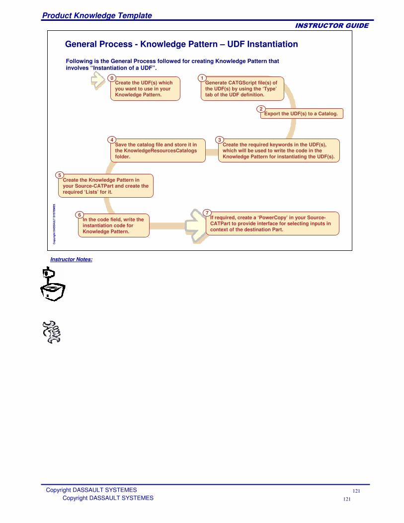
Instructor Notes:
Product Knowledge Template
Copyright DASSAULT SYSTEMES 121
��������������
Copyright DASSAULT SYSTEMES 121
Cop
yrig
ht D
AS
SA
ULT
SYS
TEM
ES
General Process - Knowledge Pattern – UDF Instantiation
Create the UDF(s) which you want to use in your Knowledge Pattern.
0
Export the UDF(s) to a Catalog.2
If required, create a ‘PowerCopy’ in your Source-CATPart to provide interface for selecting inputs in context of the destination Part.
7
Generate CATGScript file(s) of the UDF(s) by using the ‘Type’tab of the UDF definition.
1
Create the required keywords in the UDF(s), which will be used to write the code in the Knowledge Pattern for instantiating the UDF(s).
3
Create the Knowledge Pattern in your Source-CATPart and create the required ‘Lists’ for it.
5
Save the catalog file and store it in the KnowledgeResourcesCatalogs folder.
4
Following is the General Process followed for creating Knowledge Pattern that involves “Instantiation of a UDF”.
In the code field, write the instantiation code for Knowledge Pattern.
6
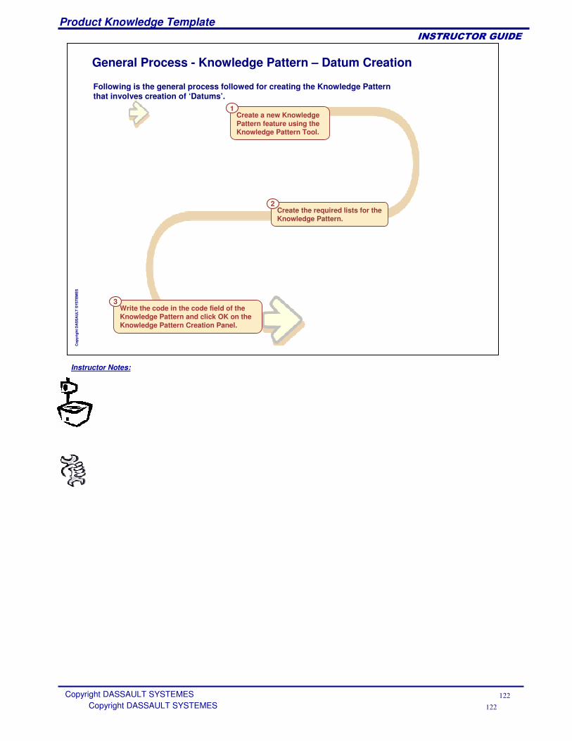
Instructor Notes:
Product Knowledge Template
Copyright DASSAULT SYSTEMES 122
��������������
Copyright DASSAULT SYSTEMES 122
Cop
yrig
ht D
AS
SA
ULT
SYS
TEM
ES
General Process - Knowledge Pattern – Datum Creation
Create a new Knowledge Pattern feature using the Knowledge Pattern Tool.
1
Write the code in the code field of the Knowledge Pattern and click OK on the Knowledge Pattern Creation Panel.
3
Create the required lists for the Knowledge Pattern.
2
Following is the general process followed for creating the Knowledge Pattern that involves creation of ‘Datums’.
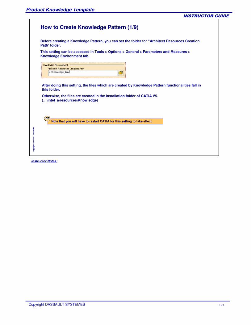
Instructor Notes:
Product Knowledge Template
Copyright DASSAULT SYSTEMES 123
��������������
Cop
yrig
ht D
AS
SA
ULT
SYS
TEM
ES
How to Create Knowledge Pattern (1/9)
Before creating a Knowledge Pattern, you can set the folder for “Architect Resources Creation Path’ folder.
This setting can be accessed in Tools > Options > General > Parameters and Measures > Knowledge Environment tab.
After doing this setting, the files which are created by Knowledge Pattern functionalities fall in this folder.
Otherwise, the files are created in the installation folder of CATIA V5. (…\intel_a\resources\Knowledge)
Note that you will have to restart CATIA for this setting to take effect.
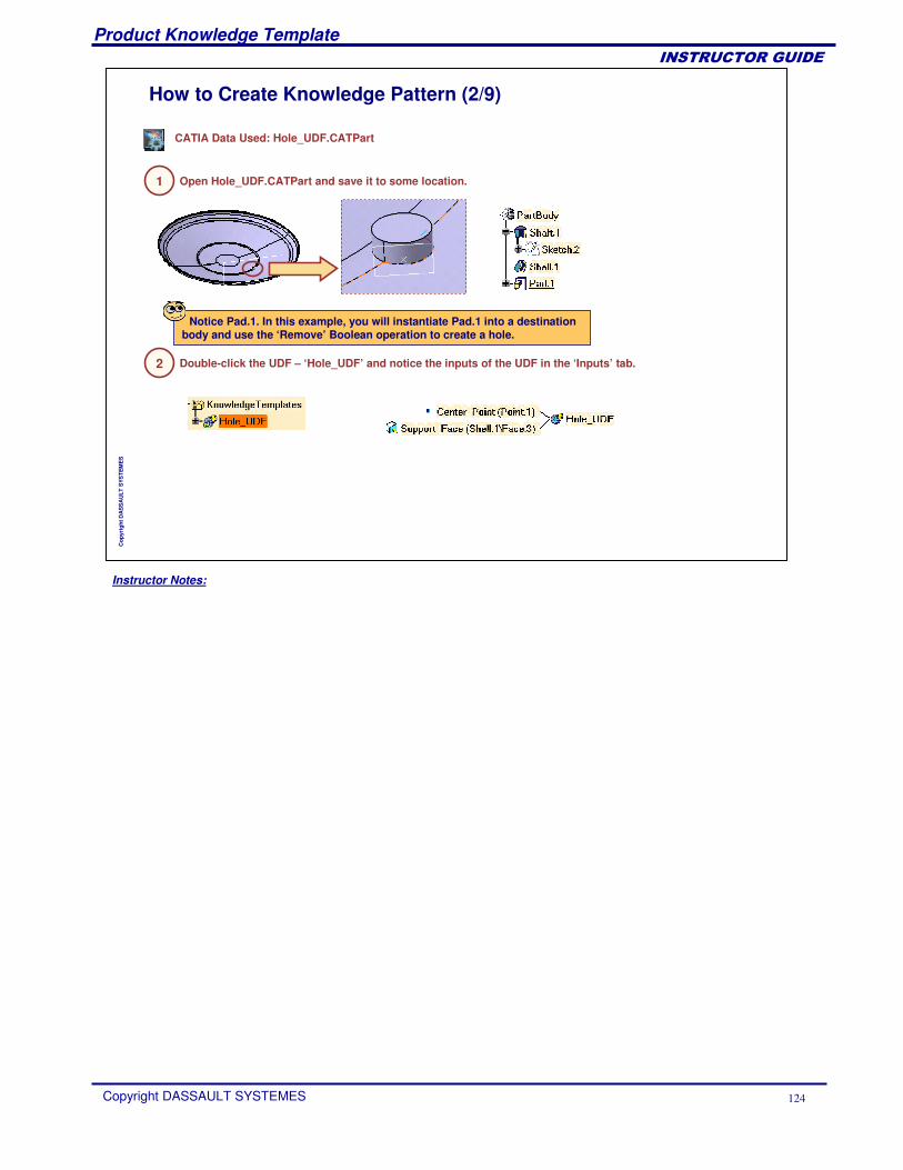
Instructor Notes:
Product Knowledge Template
Copyright DASSAULT SYSTEMES 124
��������������
Cop
yrig
ht D
AS
SA
ULT
SYS
TEM
ES
How to Create Knowledge Pattern (2/9)
1 Open Hole_UDF.CATPart and save it to some location.
2
CATIA Data Used: Hole_UDF.CATPart
Double-click the UDF – ‘Hole_UDF’ and notice the inputs of the UDF in the ‘Inputs’ tab.
Notice Pad.1. In this example, you will instantiate Pad.1 into a destination body and use the ‘Remove’ Boolean operation to create a hole.
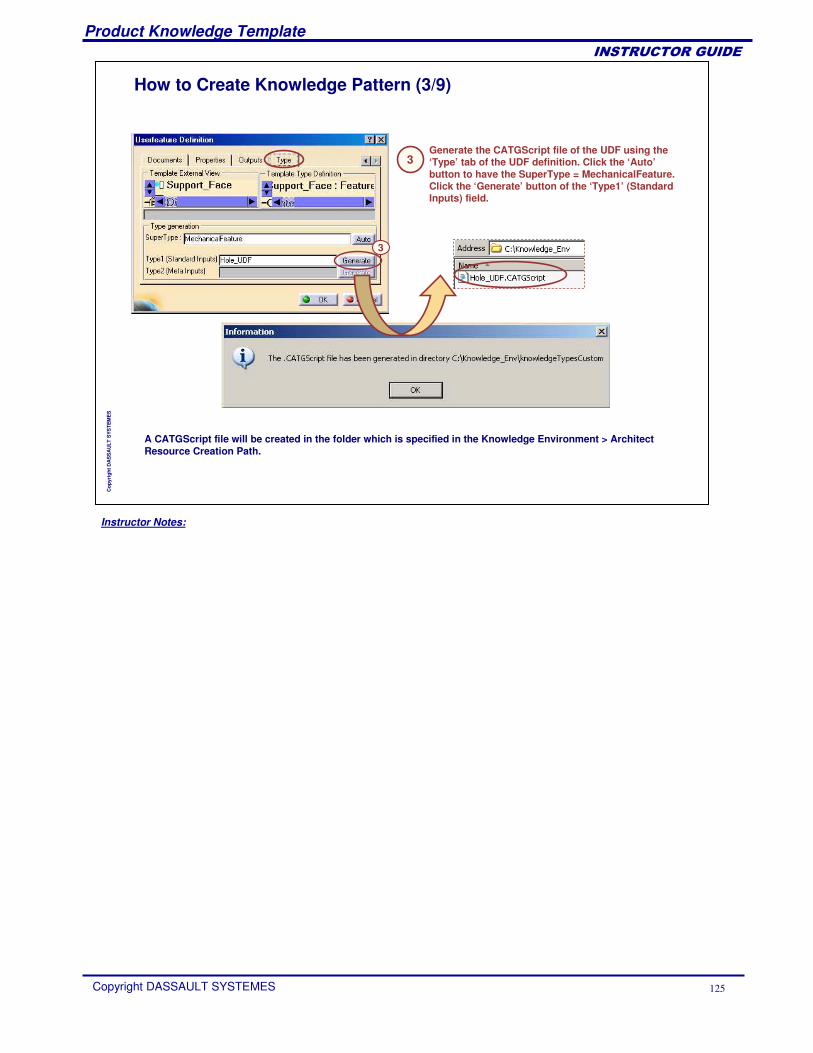
Instructor Notes:
Product Knowledge Template
Copyright DASSAULT SYSTEMES 125
��������������
Cop
yrig
ht D
AS
SA
ULT
SYS
TEM
ES
How to Create Knowledge Pattern (3/9)
3Generate the CATGScript file of the UDF using the ‘Type’ tab of the UDF definition. Click the ‘Auto’button to have the SuperType = MechanicalFeature. Click the ‘Generate’ button of the ‘Type1’ (Standard Inputs) field.
3
A CATGScript file will be created in the folder which is specified in the Knowledge Environment > Architect Resource Creation Path.
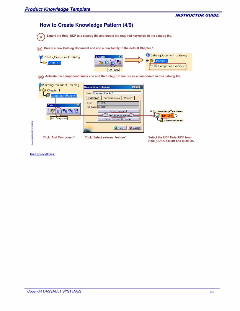
Instructor Notes:
Product Knowledge Template
Copyright DASSAULT SYSTEMES 126
��������������
Cop
yrig
ht D
AS
SA
ULT
SYS
TEM
ES
How to Create Knowledge Pattern (4/9)
4 Export the Hole_UDF to a catalog file and create the required keywords in the catalog file.
4a Create a new Catalog Document and add a new family to the default Chapter.1.
4b Activate the component family and add the Hole_UDF feature as a component in this catalog file.
Click ‘Add Component’ Click ‘Select external feature’ Select the UDF Hole_UDF from Hole_UDF.CATPart and click OK
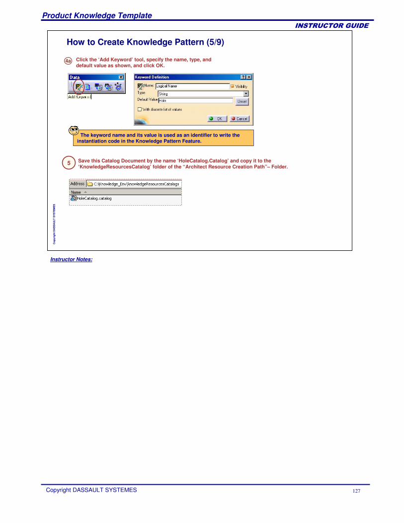
Instructor Notes:
Product Knowledge Template
Copyright DASSAULT SYSTEMES 127
��������������
Cop
yrig
ht D
AS
SA
ULT
SYS
TEM
ES
How to Create Knowledge Pattern (5/9)
4a Click the ‘Add Keyword’ tool, specify the name, type, and default value as shown, and click OK.
The keyword name and its value is used as an identifier to write the instantiation code in the Knowledge Pattern Feature.
5 Save this Catalog Document by the name ‘HoleCatalog.Catalog’ and copy it to the ‘KnowledgeResourcesCatalog’ folder of the “Architect Resource Creation Path”– Folder.
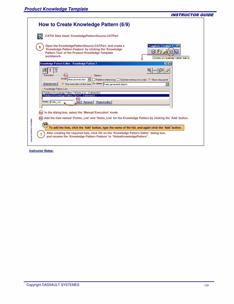
Instructor Notes:
Product Knowledge Template
Copyright DASSAULT SYSTEMES 128
��������������
Cop
yrig
ht D
AS
SA
ULT
SYS
TEM
ES
How to Create Knowledge Pattern (6/9)
6 Open the KnowledgePatternSource.CATPart, and create a ‘Knowledge Pattern Feature’ by clicking the ‘Knowledge Pattern Tool’ of the Product Knowledge Template workbench.
CATIA Data Used: KnowledgePatternSource.CATPart
6a
6b
6a In the dialog box, select the ‘Manual Execution’ mode.
6b Add the lists named ‘Points_List’ and ‘Holes_List’ for the Knowledge Pattern by clicking the ‘Add’ button.
To add the lists, click the ‘Add’ button, type the name of the list, and again click the ‘Add’ button.
7 After creating the required lists, click OK on the ‘Knowledge Pattern Editor’ dialog box, and rename the ‘Knowledge Pattern Feature’ to “HolesKnowledgePattern”.
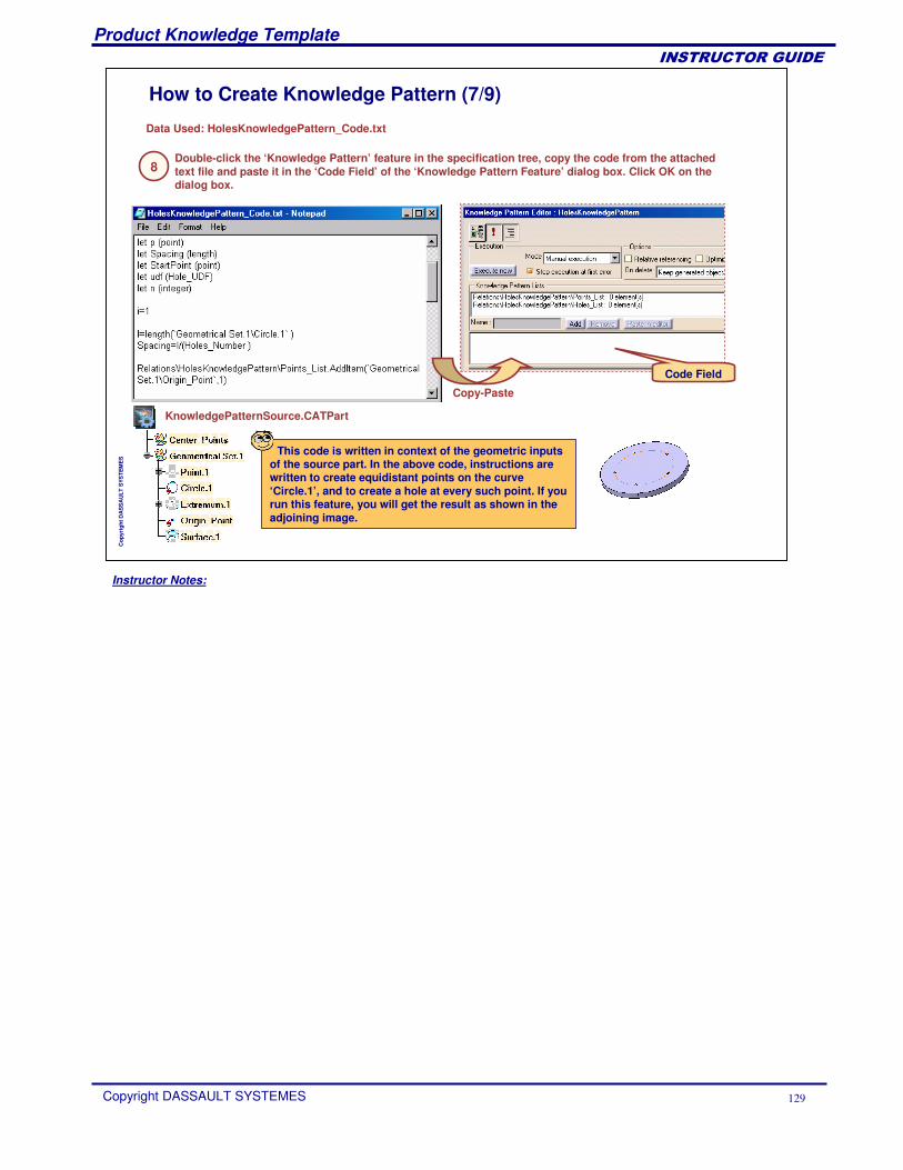
Instructor Notes:
Product Knowledge Template
Copyright DASSAULT SYSTEMES 129
��������������
Cop
yrig
ht D
AS
SA
ULT
SYS
TEM
ES
How to Create Knowledge Pattern (7/9)
8
Data Used: HolesKnowledgePattern_Code.txt
Double-click the ‘Knowledge Pattern’ feature in the specification tree, copy the code from the attached text file and paste it in the ‘Code Field’ of the ‘Knowledge Pattern Feature’ dialog box. Click OK on the dialog box.
Code Field
Copy-Paste
This code is written in context of the geometric inputs of the source part. In the above code, instructions are written to create equidistant points on the curve ‘Circle.1’, and to create a hole at every such point. If you run this feature, you will get the result as shown in the adjoining image.
KnowledgePatternSource.CATPart
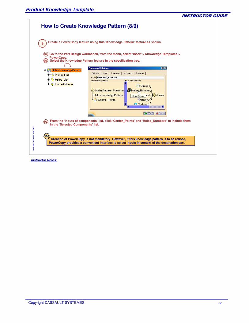
Instructor Notes:
Product Knowledge Template
Copyright DASSAULT SYSTEMES 130
��������������
Cop
yrig
ht D
AS
SA
ULT
SYS
TEM
ES
How to Create Knowledge Pattern (8/9)
9 Create a PowerCopy feature using this ‘Knowledge Pattern’ feature as shown.
Go to the Part Design workbench, from the menu, select ‘Insert > Knowledge Templates > PowerCopy.
9a
Select the Knowledge Pattern feature in the specification tree. 9b
From the ‘Inputs of components’ list, click ‘Center_Points’ and ‘Holes_Numbers’ to include them in the ‘Selected Components’ list.
9c
Creation of PowerCopy is not mandatory. However, if this knowledge pattern is to be reused, PowerCopy provides a convenient interface to select inputs in context of the destination part.
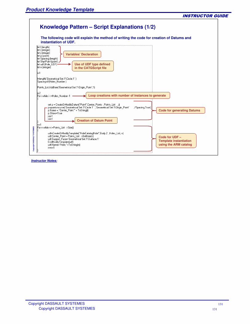
Instructor Notes:
Product Knowledge Template
Copyright DASSAULT SYSTEMES 131
��������������
Copyright DASSAULT SYSTEMES 131
Cop
yrig
ht D
AS
SA
ULT
SYS
TEM
ES
Knowledge Pattern – Script Explanations (1/2)
The following code will explain the method of writing the code for creation of Datums and instantiation of UDF.
Variables’ Declaration
Loop creations with number of instances to generate
Code for generating Datums
Code for UDF –Template instantiation using the ARM catalog
Use of UDF type defined in the CATGScript file
Creation of Datum Point
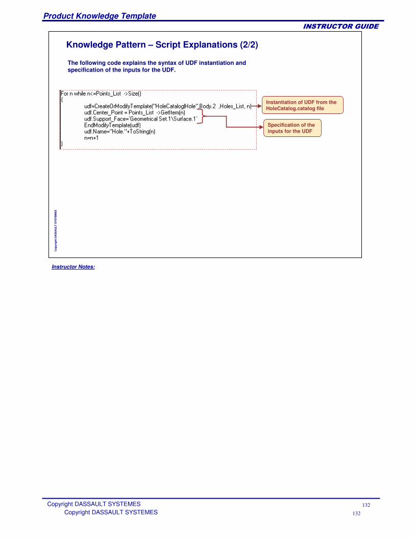
Instructor Notes:
Product Knowledge Template
Copyright DASSAULT SYSTEMES 132
��������������
Copyright DASSAULT SYSTEMES 132
Cop
yrig
ht D
AS
SA
ULT
SYS
TEM
ES
Knowledge Pattern – Script Explanations (2/2)
Instantiation of UDF from the HoleCatalog.catalog file
Specification of the inputs for the UDF
The following code explains the syntax of UDF instantiation and specification of the inputs for the UDF.
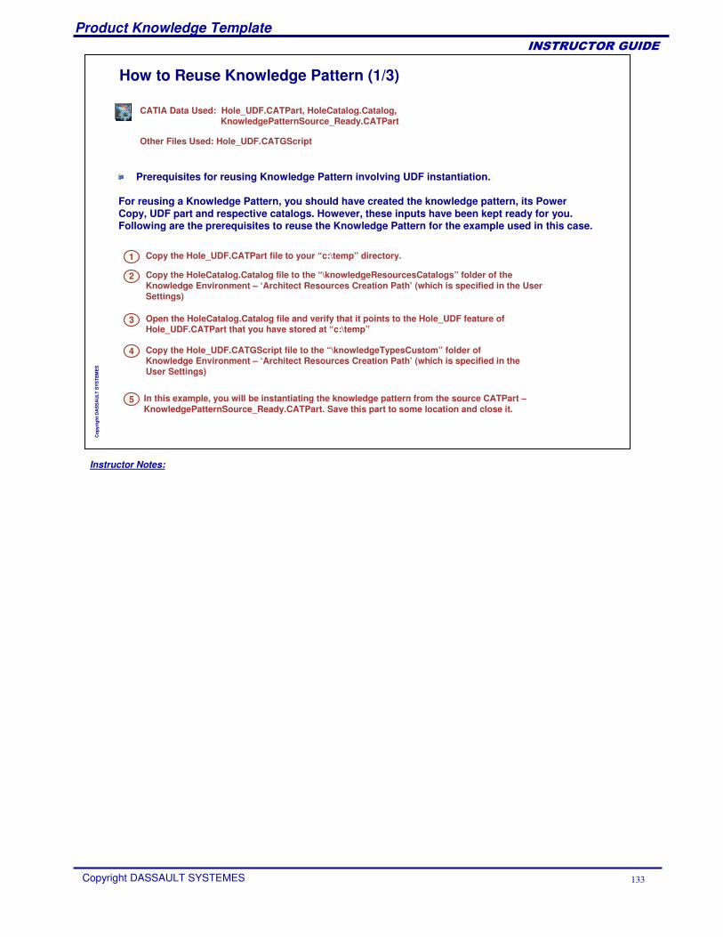
Instructor Notes:
Product Knowledge Template
Copyright DASSAULT SYSTEMES 133
��������������
Cop
yrig
ht D
AS
SA
ULT
SYS
TEM
ES
How to Reuse Knowledge Pattern (1/3)
Copy the Hole_UDF.CATPart file to your “c:\temp” directory.
CATIA Data Used: Hole_UDF.CATPart, HoleCatalog.Catalog,KnowledgePatternSource_Ready.CATPart
Other Files Used: Hole_UDF.CATGScript
Prerequisites for reusing Knowledge Pattern involving UDF instantiation.
For reusing a Knowledge Pattern, you should have created the knowledge pattern, its Power Copy, UDF part and respective catalogs. However, these inputs have been kept ready for you. Following are the prerequisites to reuse the Knowledge Pattern for the example used in this case.
1
Copy the HoleCatalog.Catalog file to the “\knowledgeResourcesCatalogs” folder of the Knowledge Environment – ‘Architect Resources Creation Path’ (which is specified in the User Settings)
2
Open the HoleCatalog.Catalog file and verify that it points to the Hole_UDF feature of Hole_UDF.CATPart that you have stored at “c:\temp”
3
Copy the Hole_UDF.CATGScript file to the “\knowledgeTypesCustom” folder of Knowledge Environment – ‘Architect Resources Creation Path’ (which is specified in the User Settings)
4
In this example, you will be instantiating the knowledge pattern from the source CATPart –KnowledgePatternSource_Ready.CATPart. Save this part to some location and close it.
5
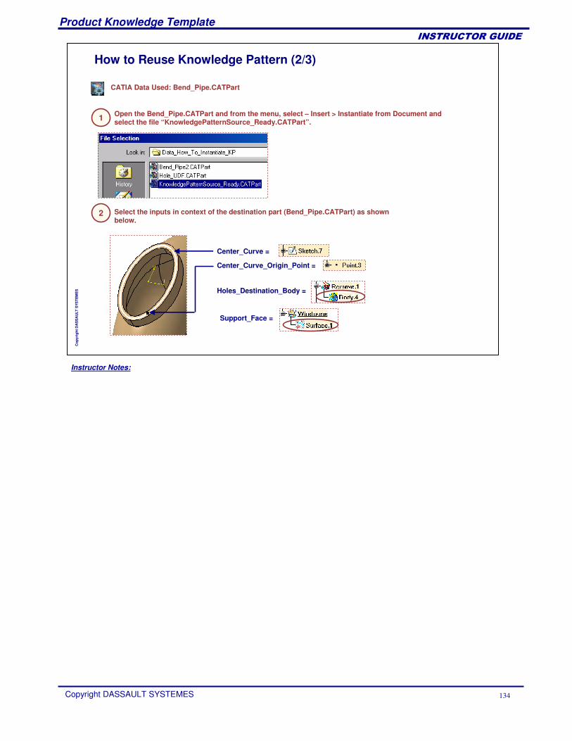
Instructor Notes:
Product Knowledge Template
Copyright DASSAULT SYSTEMES 134
��������������
Cop
yrig
ht D
AS
SA
ULT
SYS
TEM
ES
How to Reuse Knowledge Pattern (2/3)
1
CATIA Data Used: Bend_Pipe.CATPart
Open the Bend_Pipe.CATPart and from the menu, select – Insert > Instantiate from Document and select the file “KnowledgePatternSource_Ready.CATPart”.
2 Select the inputs in context of the destination part (Bend_Pipe.CATPart) as shown below.
Center_Curve =
Center_Curve_Origin_Point =
Holes_Destination_Body =
Support_Face =
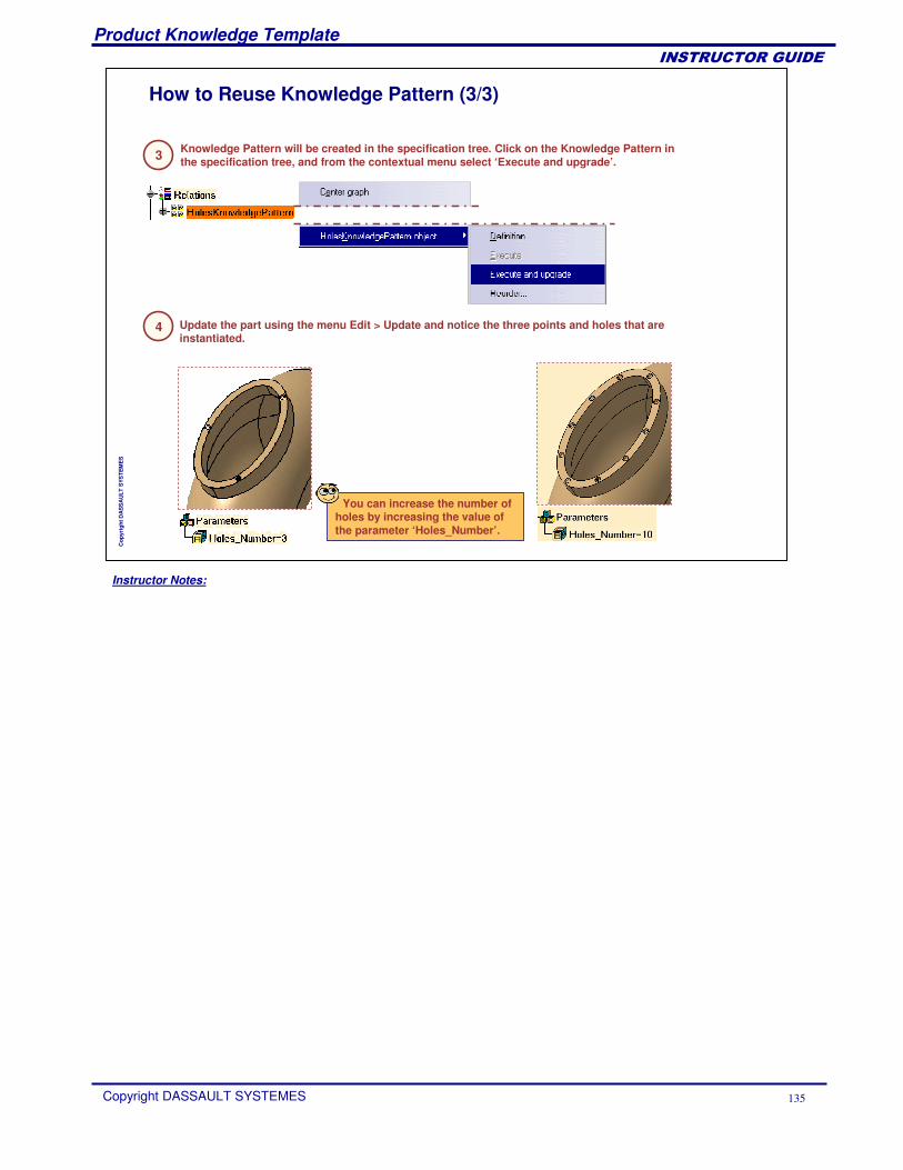
Instructor Notes:
Product Knowledge Template
Copyright DASSAULT SYSTEMES 135
��������������
Cop
yrig
ht D
AS
SA
ULT
SYS
TEM
ES
How to Reuse Knowledge Pattern (3/3)
3 Knowledge Pattern will be created in the specification tree. Click on the Knowledge Pattern in the specification tree, and from the contextual menu select ‘Execute and upgrade’.
4 Update the part using the menu Edit > Update and notice the three points and holes that are instantiated.
You can increase the number of holes by increasing the value of the parameter ‘Holes_Number’.
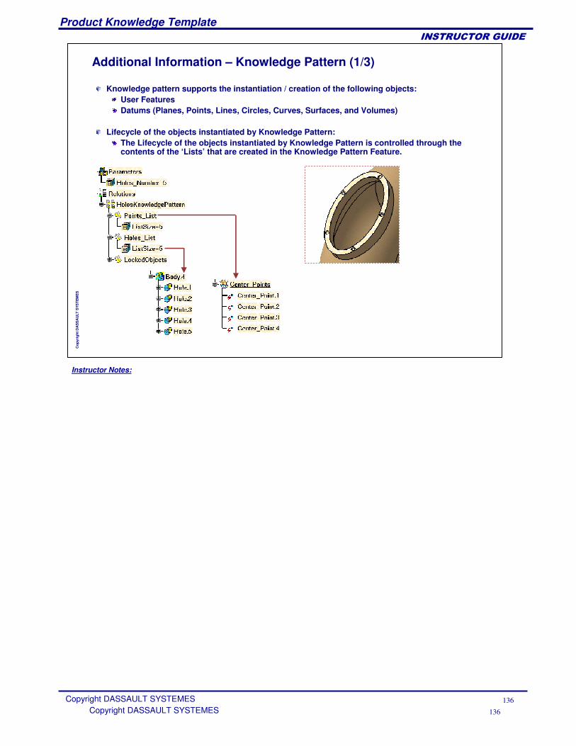
Instructor Notes:
Product Knowledge Template
Copyright DASSAULT SYSTEMES 136
��������������
Copyright DASSAULT SYSTEMES 136
Cop
yrig
ht D
AS
SA
ULT
SYS
TEM
ES
Additional Information – Knowledge Pattern (1/3)
Knowledge pattern supports the instantiation / creation of the following objects:User FeaturesDatums (Planes, Points, Lines, Circles, Curves, Surfaces, and Volumes)
Lifecycle of the objects instantiated by Knowledge Pattern:The Lifecycle of the objects instantiated by Knowledge Pattern is controlled through the contents of the ‘Lists’ that are created in the Knowledge Pattern Feature.
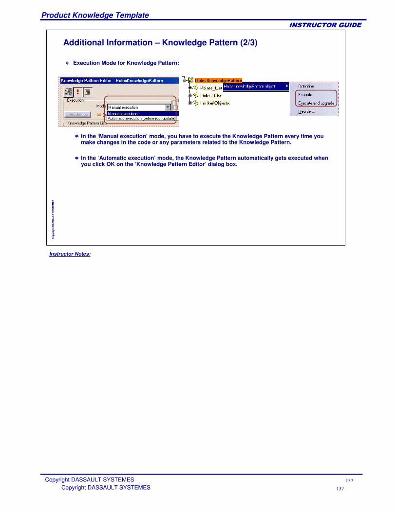
Instructor Notes:
Product Knowledge Template
Copyright DASSAULT SYSTEMES 137
��������������
Copyright DASSAULT SYSTEMES 137
Cop
yrig
ht D
AS
SA
ULT
SYS
TEM
ES
Additional Information – Knowledge Pattern (2/3)
Execution Mode for Knowledge Pattern:
In the ‘Manual execution’ mode, you have to execute the Knowledge Pattern every time you make changes in the code or any parameters related to the Knowledge Pattern.
In the ‘Automatic execution’ mode, the Knowledge Pattern automatically gets executed when you click OK on the ‘Knowledge Pattern Editor’ dialog box.
Instructor Notes:
Product Knowledge Template
Copyright DASSAULT SYSTEMES 138
��������������
Copyright DASSAULT SYSTEMES 138
Cop
yrig
ht D
AS
SA
ULT
SYS
TEM
ES
Additional Information – Knowledge Pattern (3/3)
Knowledge Pattern assures associativity of the instantiated objects.
The instantiated objects are associative with respect to:
The inputs defining the Knowledge PatternThe number of instancesThe generated datumsParameter values of the instances
Instructor Notes:
Product Knowledge Template
Copyright DASSAULT SYSTEMES 139
��������������
Copyright DASSAULT SYSTEMES 139
Cop
yrig
ht D
AS
SA
ULT
SYS
TEM
ES
The concept of ‘Knowledge Pattern’Its applicationsMethods to create and reuse ‘Knowledge Pattern’Guidelines to write the code of ‘Knowledge Pattern’
To Sum Up
In this lesson, you have learned:
Instructor Notes:
Product Knowledge Template
Copyright DASSAULT SYSTEMES 140
��������������
Cop
yrig
ht D
AS
SA
ULT
SYS
TEM
ES
To Sum Up ...
In this course you have seen:
How to use PowerCopiesHow to use User Define FeaturesHow to use Part and Assembly TemplatesHow to manage standard componentsHow to use advance replication tools like Knowledge Pattern