prospect / retrospect optimising the specifications 2011 current... · safety margins is considered...
TRANSCRIPT

In these days of global competition,when we compare our Indian productswith internationally available products,we feel that our products are bulky.They appear to be extremelyvoluminous compared to theirinternational equivalents.
In order to fight the fierce competition,we wish the products were compact,affordable and could still deliveroutstanding performance with respectto the expectations written down in thespecifications. With this begins thecontradiction.
Internationally, the productspecifications are laid down withpractical, realistic approach. In India,normally, we try to build cushions ateach level of indicating requirements.
For example, even for a distributionboard with 100A incomer,connected through cables, wenormally specify a fault level whichis the same as the transformerincomer level - say 50kA.
When a busbar cross section of 50sq.mm. is adequate, we land upwith 500 sq.mm. That too with acomplicated and expensivesupporting arrangement.
Similarly, when a mechanicalprocess requires a drive of 11kW,the concerned engineer indicates arequirement of 15kW. Finally, theelectrical motor is produced foreither 18.5kW or 22kW. The CTprimary current is specified as 50Aand probably a contactor of 70Arating for an actual load of 20A.
Ultimately, all this occupies spaceand costs money to the end user.
Realistic specifications result in costeffective arrangements. As againstthat, over specifications result inexpensive, bulky and uneconomicalequipment.
But this does not mean that safetymargins are not to be consideredwhile giving initial specifications. Butsafety should be built in carefully,keeping practical application in mind.
On the contrary, more stress shouldbe placed, and margins or cushionshave to be retained or built up withrespect to personnel and operationalsafety, maintainability of theequipment, accessibility, life timedurability,…
Issued by: Electrical Systems & Equipment LARSEN & TOUBRO LIMITED, Powai Works, Mumbai 400 072
Prospect / Retrospect
January - March 2001
OPTIMISING THE SPECIFICATIONS
Visit us at www.LNTEBG.com
Wcoitsdoultplavaacsp
WhSpanThfunto abeqonpla
Sinof chcoEvreqformialsvapla
Spscthewhadindex
CospWdotaktheshpacobuwhsa
FEATURE
MAKING COST EFFECTIVE SPECIFICATIONS FOR LV SWITCHGEAR- Mr. R. S. Mahajan, Ms. Neelam Kotnis
henever any project isnceptualised, the specifications for various equipment are writtenwn. It is a very important step, asimately the smooth running of thent in the long run depends on the
rious considerations taken intocount during the drafting of theecifications.
y specifications?ecifications define the requirementsd expectations of the user clearly.ey not only list down the variousctions that an equipment is requiredcarry out, but also lay guidelines
out the expected performance of theuipment and its inter-dependence the other parts or equipment in thent.
ce specifications define the framedesired and expected
aracteristics, they provide ammon base for all the bidders.erybody is clear about theuirement and every bidder quotes the equipment of the samenimum capacity and capability. Thiso makes the comparison of therious prices easy since a commontform is defined.
ecifications also encompass theope of supply. The supplier knows extent of work involved on his part,ich he can plan very well invance and he can even give clearications to the purchaser about the
pected time to complete the job.
nsiderations while definingecificationshen the Project Engineers writewn the specifications, they need toe into account funds available for basic project. In addition, they
ould also take care of variousrameters like expected sitenditions, payback period, futuresiness plans and so on. Hence,ile writing down the specifications,fety margins is considered to take
care of variations, if any, in the initialassumptions.
In practice, what happens is, safetymargins get added at each andevery step.
The result?It results in oversized equipment andoverall expensive arrangement. Ov-er specification does not necessarilymean more safety, longer life andbetter performance. Over -specifications do not necessarily addvalue to the performance/operations.On the contrary, sometimes, over-specifications may deteriorate theperformance.
Hence, it is the extremely essentialto critically review the specificationsfor all the equipment when we areoptimising the cost of a project.Electrical equipment likeswitchboards is influenced bymechanical and process inputs andcushions at every stage result inoversized, non-optimizedswitchboards. In this article, we bringforward some of the points in LVswitchboard specs which need to bepondered upon while drafting thespecifications.
1. Current Transformers -Accuracy and Burden :Many a time, CTs are specified withmetering accuracy of Class 1 andthe burden of 15VA. Such CTs arenormally connected with an ammeteror may be a transducer. The burdenof these is in the order of 1.5-2VA.The point to be noted here is that CTaccuracy is valid when loadconnected to it is above 25% of therated burden. Hence, a 15VA CTwhen used with only an Ammeter orTransducer or even aMicroprocessor based relay will notgive the required accuracy. Hence, itis desirable to go for a 2VA or at themost 5VA burden CTs for suchapplications.
It is also believed that protectionCTs like 5P10, are meant only for
protection and hence separate CTsare considered for metering, evenwhen Microprocessor based Intelligentrelays are used. It is to be noted that aprotection CT with accuracy class5P10 gives 1% accuracy (same asClass 1 CT) for normal currents. Aprotection CT of class 5P10, burden2VA used with integrated protectionand metering relay offers the mostoptimum arrangement.
2. Component ratingsSome of the consultants specificallyask for a minimum power switch of63A rating and 32A contactor even forlower rated starters. This concept wasappropriate in early days, prior toIS13947. Now, the switches haveAC23 ratings and the contactors aresuitable for AC3/AC4 duty. Hence, itshould be ensured that the switchesand contactors have adequateAC23/AC3 ratings respectively.Specifying higher ratings only adds tothe cost.
3. VT Burden & AccuracySimilar to CTs, even in case of VTs,since the connected burden is verylow, the VTs do not give ratedaccuracy in measurement. Forexample, when there are two undervoltage relays in the line VT circuit ortwo under voltage and two no voltagerelays in the bus VT circuit, they havea maximum of 8VA burden withelectromechanical relays. Then 50VAor 100VA VTs is not the right choice.A 20/25VA VT is adequate. In case ofHT switchgear, where in addition tomultiple protection relays, evenenergy meters are normally connectedon the bus VT, a higher VT burdenmay be essential.
4. Separate meters and lock outrelays with Intelligent relaysWhen comprehensive Intelligentrelays with protection, metering andannunciation features are used,extensive metering data is availableon them. Still, many of our plants
demand separate analog meters andindicating lamps. Also, such relayscan be programmed for using built-inlock our feature, thereby eliminatingseparate relay. However, here again,in addition to this Intelligent relay, aseparate lock out relay is asked for.This not only adds to the cost but alsodeprives the user of a communicationbased reset feature.
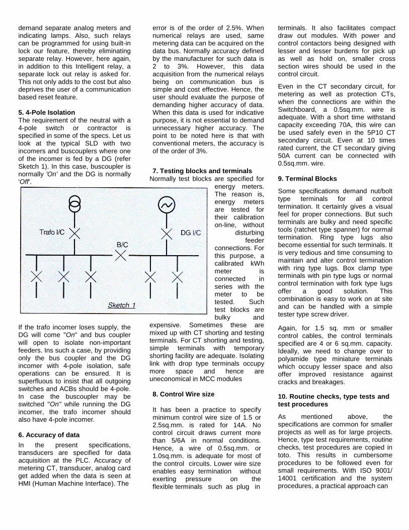
5. 4-Pole IsolationThe requirement of the neutral with a4-pole switch or contractor isspecified in some of the specs. Let uslook at the typical SLD with twoincomers and buscouplers where oneof the incomer is fed by a DG (referSketch 1). In this case, buscoupler isnormally 'On' and the DG is normally'Off'.
If the trafo incomer loses supply, theDG will come "On" and bus couplerwill open to isolate non-importantfeeders. Ins such a case, by providingonly the bus coupler and the DGincomer with 4-pole isolation, safeoperations can be ensured. It issuperfluous to insist that all outgoingswitches and ACBs should be 4-pole.In case the buscoupler may beswitched "On" while running the DGincomer, the trafo incomer shouldalso have 4-pole incomer.
6. Accuracy of dataIn the present specifications,transducers are specified for dataacquisition at the PLC. Accuracy ofmetering CT, transducer, analog cardget added when the data is seen atHMI (Human Machine Interface). The
error is of the order of 2.5%. Whennumerical relays are used, samemetering data can be acquired on thedata bus. Normally accuracy definedby the manufacturer for such data is2 to 3%. However, this dataacquisition from the numerical relaysbeing on communication bus issimple and cost effective. Hence, theuser should evaluate the purpose ofdemanding higher accuracy of data.When this data is used for indicativepurpose, it is not essential to demandunnecessary higher accuracy. Thepoint to be noted here is that withconventional meters, the accuracy isof the order of 3%.
7. Testing blocks and terminalsNormally test blocks are specified for
energy meters.The reason is,energy metersare tested fortheir calibrationon-line, without
disturbingfeeder
connections. Forthis purpose, acalibrated kWhmeter isconnected inseries with themeter to betested. Suchtest blocks arebulky and
expensive. Sometimes these aremixed up with CT shorting and testingterminals. For CT shorting and testing,simple terminals with temporaryshorting facility are adequate. Isolatinglink with drop type terminals occupymore space and hence areuneconomical in MCC modules
8. Control Wire size
It has been a practice to specifyminimum control wire size of 1.5 or2.5sq.mm. is rated for 14A. Nocontrol circuit draws current morethan 5/6A in normal conditions.Hence, a wire of 0.5sq.mm. or1.0sq.mm. is adequate for most ofthe control circuits. Lower wire sizeenables easy termination withoutexerting pressure on theflexible terminals such as plug in
terminals. It also facilitates compactdraw out modules. With power andcontrol contactors being designed withlesser and lesser burdens for pick upas well as hold on, smaller crosssection wires should be used in thecontrol circuit.
Even in the CT secondary circuit, formetering as well as protection CTs,when the connections are within theSwitchboard, a 0.5sq.mm. wire isadequate. With a short time withstandcapacity exceeding 70A, this wire canbe used safely even in the 5P10 CTsecondary circuit. Even at 10 timesrated current, the CT secondary giving50A current can be connected with0.5sq.mm. wire.
9. Terminal Blocks
Some specifications demand nut/bolttype terminals for all controltermination. It certainly gives a visualfeel for proper connections. But suchterminals are bulky and need specifictools (ratchet type spanner) for normaltermination. Ring type lugs alsobecome essential for such terminals. Itis very tedious and time consuming tomaintain and alter control terminationwith ring type lugs. Box clamp typeterminals with pin type lugs or normalcontrol termination with fork type lugsoffer a good solution. Thiscombination is easy to work on at siteand can be handled with a simpletester type screw driver.
Again, for 1.5 sq. mm or smallercontrol cables, the control terminalsspecified are 4 or 6 sq.mm. capacity.Ideally, we need to change over topolyamide type miniature terminalswhich occupy lesser space and alsooffer improved resistance againstcracks and breakages.
10. Routine checks, type tests andtest procedures
As mentioned above, thespecifications are common for smallerprojects as well as for large projects.Hence, type test requirements, routinechecks, test procedures are copied intoto. This results in cumbersomeprocedures to be followed even forsmall requirements. With ISO 9001/14001 certification and the systemprocedures, a practical approach can

be adopted for routine checks and testprocedures. Periodically of type testcertificates also need to be practicalconsidering wide range of products tobe tested and being used. Recentstandards (IS13947 series) have madetype tests procedure stringent andlaborious. Sometimes it is experiencedthat formality to complete type testresults in delays in equipmentprocurement and thereby projectcommissioning.
So far we have listed some of thepoints where optimisation inspecifications is desired. However,features which build up safety foroperations and longer life need to bestressed categorically. Some suchfeatures which require moreelaboration in the specifications are asfollows:
1. Safety
Safety of the personnel and equipmentis of utmost importance. There can notbe any compromise in this respect.Hence, specifications must definewhat safety features are essential inthe switchboard e.g.• Barriers are essential for
separating live parts• Segregation in compartments and
busbar chamber is necessary toprevent shorting due to fallinghardware etc.
• Shrouding arrangement should besuch that any time one should notbe able to touch any live partinadvertently after opening theswitchboards door.
2. Neutral busbars
Neutral should be given the sameconsideration as busbars. In fact, itshould be considered an integral partof the entire busbar system. Thus itshould have the same fault withstandcapacity as the main busbars.
3. Fault withstand
The specifications also define whatshould be the fault withstand capacityof the switchboard. This is based onthe rating of the transformer i.e. for a2MVA transformer, the fault withstandcapacity will be 43kA. But wherevertwo transformers are feeding and thereis a possibility of their gettingmomentarily paralleled, higher faultwithstand capacity should beconsidered for the busbars.
4. Redundancy in communication
With numerical relays andcommunication system becoming apart of the specifications, some moreaspects are coming into the picture.The communication network is the
Crucial part of this system. Continuousacquisition of this data is veryessential. This can be positivelyachieved by building redundancy in thesystem (as shown in Sketch 2). Here,any breakage in the link does nothamper the communication as all therelays are connected to two separatecards to build dual redundancy.
5. Temperature rise
Temperature rise constrains are veryimportant in switchgear, specially inIndian ambients which are very high.Hence, it is essential to adhere to thetemperature rise limits defined in thespecifications. High temperature givesrise to hot spots resulting indeterioration of insulation, higher rateof oxidation and it may also result in aflashover.
6. Accessibility for cabling
In India, we have predominant use ofaluminium cables for cabling. Hence,cable alley should be spacious enoughto accommodate multiple aluminiumcables and also to bend them withoutexerting pressure on the termination.Even terminals should be designed totake these terminations. Evensupporting system for large size cablesshould be provided ease pressure ontermination.
The cable alley should be spacious sothat there is ease in accessing theterminations which becomes veryessential specially in MCC.
7. Maintainability
Maintainability is very crucial foroperations and maintenance people.Some considerations for this are:• All the joints should be easily
accessible;• Standardisation in feeder layouts;• Interchangeability of modules
possible to reduce downtime.
ConclusionSpecifications should be a balance of: -• Optimum technical requirements;• Highest safety standards;• Sufficient life span;• Maintainability considering the life
span;• Equipment life, utility and price.
For further details on this subject, please contact:Electrical Systems & Equipment, Larsen & Toubro Limited, Saki-Vihar Road, P.O.Box 8901, Powai, Mumbai 400 072
Fax: 022-8581024 • e-mail: [email protected]
Printed by Printania Offset Pvt. Ltd., D 20/21, Shalimar Industrial Estate, Matunga (east), Mumbai 400 019. Tel: 407 7996/8866/4540Fax: 402 4703 Email: [email protected] Edited by Dr. Arun C. Vakil for larsen & toubro Limited, from L & T House, Narottam MorarjiMarg, Ballard Estate, Mumbai 400 001. The views expressed in this magazine are not necessarily those of the management of larsen& Toubro Limited. The contacts of this magazine should not be reproduced without the written permission of the Editor. Not for sale -only for Circulation among the customers. Associate Editor: Luis S. R. Vas