pv 6 compact mixer operations guide - american musical supply · ®6 compact mixer operations guide...
TRANSCRIPT
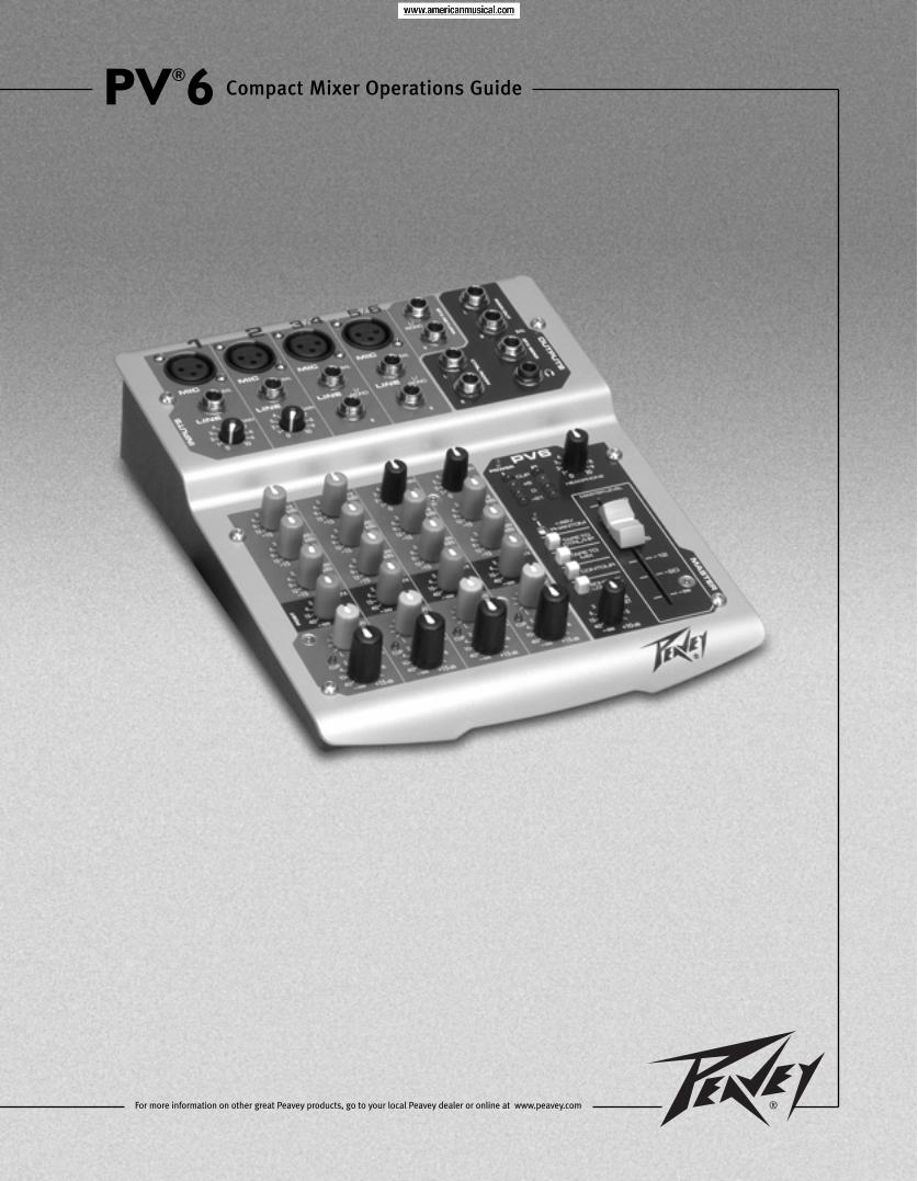
PV®6 Compact Mixer Operations Guide
For more information on other great Peavey products, go to your local Peavey dealer or online at www.peavey.com
2
Intended to alert the user to the presence of uninsulated “dangerous voltage” within the product’senclosure that may be of sufficient magnitude to constitute a risk of electric shock to persons.
Intended to alert the user of the presence of important operating and maintenance (servicing)instructions in the literature accompanying the product.
CCAAUUTTIIOONN:: Risk of electrical shock — DO NOT OPEN!CCAAUUTTIIOONN:: To reduce the risk of electric shock, do not remove cover. No user serviceable parts inside.Refer servicing to qualified service personnel.
WWAARRNNIINNGG:: To prevent electrical shock or fire hazard, do not expose this appliance to rain or moisture.Before using this appliance, read the operating guide for further warnings.
Este símbolo tiene el propósito, de alertar al usuario de la presencia de “(voltaje) peligroso” sinaislamiento dentro de la caja del producto y que puede tener una magnitud suficiente como paraconstituir riesgo de descarga eléctrica.
Este símbolo tiene el propósito de alertar al usario de la presencia de instruccones importantes sobre laoperación y mantenimiento en la información que viene con el producto.
PPRREECCAAUUCCIIOONN:: Riesgo de descarga eléctrica ¡NO ABRIR!PPRREECCAAUUCCIIOONN:: Para disminuír el riesgo de descarga eléctrica, no abra la cubierta. No hay piezas útilesdentro. Deje todo mantenimiento en manos del personal técnico cualificado.
AADDVVEERRTTEENNCCIIAA:: Para evitar descargas eléctricas o peligro de incendio, no deje expuesto a la lluvia ohumedad este aparato Antes de usar este aparato, Iea más advertencias en la guía de operación.
Ce symbole est utilisé dans ce manuel pour indiquer à l’utilisateur la présence d’une tension dangereusepouvant être d’amplitude suffisante pour constituer un risque de choc électrique.
Ce symbole est utilisé dans ce manuel pour indiquer à l’utilisateur qu’il ou qu’elle trouvera d’importantesinstructions concernant l’utilisation et l’entretien de l’appareil dans le paragraphe signalé.
AATTTTEENNTTIIOONN:: Risques de choc électrique — NE PAS OUVRIR!AATTTTEENNTTIIOONN:: Afin de réduire le risque de choc électrique, ne pas enlever le couvercle. Il ne se trouve àl’intérieur aucune pièce pouvant être reparée par l’utilisateur. Confiez I’entretien et la réparation del’appareil à un réparateur Peavey agréé.
AAVVEERRTTIISSSSEEMMEENNTT: Afin de prévenir les risques de décharge électrique ou de feu, n’exposez pas cetappareil à la pluie ou à l’humidité. Avant d’utiliser cet appareil, lisez attentivement les avertissementssupplémentaires de ce manuel.
Dieses Symbol soll den Anwender vor unisolierten gefährlichen Spannungen innerhalb des Gehäuseswarnen, die von Ausreichender Stärke sind, um einen elektrischen Schlag verursachen zu können.
Dieses Symbol soll den Benutzer auf wichtige Instruktionen in der Bedienungsanleitung aufmerksammachen, die Handhabung und Wartung des Produkts betreffen.
VVOORRSSIICCHHTT:: Risiko — Elektrischer Schlag! Nicht öffnen!VVOORRSSIICCHHTT:: Um das Risiko eines elektrischen Schlages zu vermeiden, nicht die Abdeckung enfernen. Esbefinden sich keine Teile darin, die vom Anwender repariert werden könnten. Reparaturen nur vonqualifiziertem Fachpersonal durchführen lassen.
AACCHHTTUUNNGG:: Um einen elektrischen Schlag oder Feuergefahr zu vermeiden, sollte dieses Gerät nicht demRegen oder Feuchtigkeit ausgesetzt werden. Vor Inbetriebnahme unbedingt die Bedienungsanleitung lesen.
3
IIMMPPOORRTTAANNTT SSAAFFEETTYY IINNSSTTRRUUCCTTIIOONNSS
WWAARRNNIINNGG:: When using electrical products, basic cautions should always be followed, including the following:
1. Read these instructions.
2. Keep these instructions.
3. Heed all warnings.
4. Follow all instructions.
5. Do not use this apparatus near water.
6. Clean only with a dry cloth.
7. Do not block any of the ventilation openings. Install in accordance with manufacturer’s instructions.
8. Do not install near any heat sources such as radiators, heat registers, stoves or other apparatus (includingamplifiers) that produce heat.
9. Do not defeat the safety purpose of the polarized or grounding-type plug. A polarized plug has two blades with onewider than the other. A grounding type plug has two blades and a third grounding plug. The wide blade or thirdprong is provided for your safety. If the provided plug does not fit into your outlet, consult an electrician forreplacement of the obsolete outlet.
10. Protect the power cord from being walked on or pinched, particularly at plugs, convenience receptacles, and thepoint they exit from the apparatus.
11. Note for UK only: If the colors of the wires in the mains lead of this unit do not correspond with the terminals in yourplug‚ proceed as follows:
a) The wire that is colored green and yellow must be connected to the terminal that is marked by the letter E‚ theearth symbol‚ colored green or colored green and yellow.
b) The wire that is colored blue must be connected to the terminal that is marked with the letter N or the color black.
c) The wire that is colored brown must be connected to the terminal that is marked with the letter L or the color red.
12. Only use attachments/accessories provided by the manufacturer.
13. Use only with a cart, stand, tripod, bracket, or table specified by the manufacturer, or sold with the apparatus. Whena cart is used, use caution when moving the cart/apparatus combination to avoid injury from tip-over.
14. Unplug this apparatus during lightning storms or when unused for long periods of time.
15. Refer all servicing to qualified service personnel. Servicing is required when the apparatus has been damaged inany way, such as power-supply cord or plug is damaged, liquid has been spilled or objects have fallen into theapparatus, the apparatus has been exposed to rain or moisture, does not operate normally, or has been dropped.
16. Never break off the ground pin. Write for our free booklet “Shock Hazard and Grounding.” Connect only to a powersupply of the type marked on the unit adjacent to the power supply cord.
17. If this product is to be mounted in an equipment rack, rear support should be provided.
18. Exposure to extremely high noise levels may cause a permanent hearing loss. Individuals vary considerably insusceptibility to noise-induced hearing loss, but nearly everyone will lose some hearing if exposed to sufficientlyintense noise for a sufficient time. The U.S. Government’s Occupational and Health Administration (OSHA) hasspecified the following permissible noise level exposures:
Duration Per Day In Hours Sound Level dBA, Slow Response8 906 924 953 972 100
1 1⁄2 1021 1051⁄2 110
1⁄4 or less 115
According to OSHA, any exposure in excess of the above permissible limits could result in some hearing loss. Ear plugs or protectors to theear canals or over the ears must be worn when operating this amplification system in order to prevent a permanent hearing loss, if exposureis in excess of the limits as set forth above. To ensure against potentially dangerous exposure to high sound pressure levels, it isrecommended that all persons exposed to equipment capable of producing high sound pressure levels such as this amplification system beprotected by hearing protectors while this unit is in operation.
SSAAVVEE TTHHEESSEE IINNSSTTRRUUCCTTIIOONNSS!!
4
PV®6 Compact Mixer
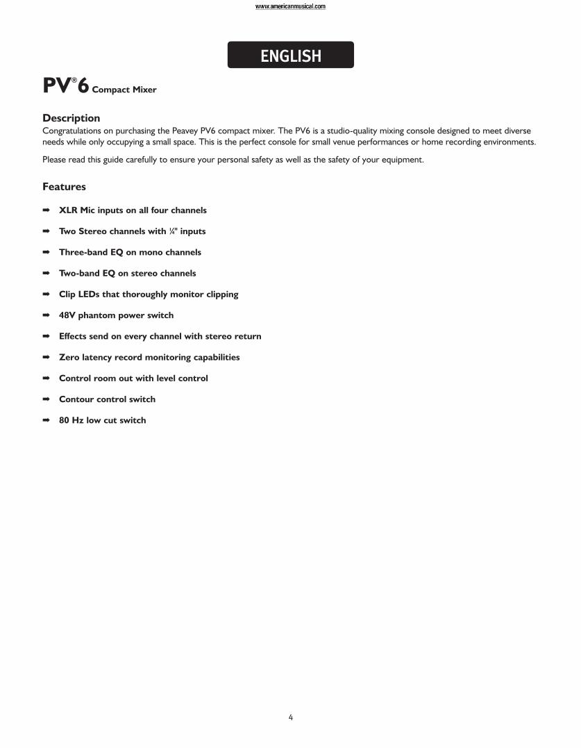
DescriptionCongratulations on purchasing the Peavey PV6 compact mixer. The PV6 is a studio-quality mixing console designed to meet diverseneeds while only occupying a small space. This is the perfect console for small venue performances or home recording environments.
Please read this guide carefully to ensure your personal safety as well as the safety of your equipment.
Features
➡ XLR Mic inputs on all four channels
➡ Two Stereo channels with 1⁄4" inputs
➡ Three-band EQ on mono channels
➡ Two-band EQ on stereo channels
➡ Clip LEDs that thoroughly monitor clipping
➡ 48V phantom power switch
➡ Effects send on every channel with stereo return
➡ Zero latency record monitoring capabilities
➡ Control room out with level control
➡ Contour control switch
➡ 80 Hz low cut switch
EENNGGLLIISSHH
5
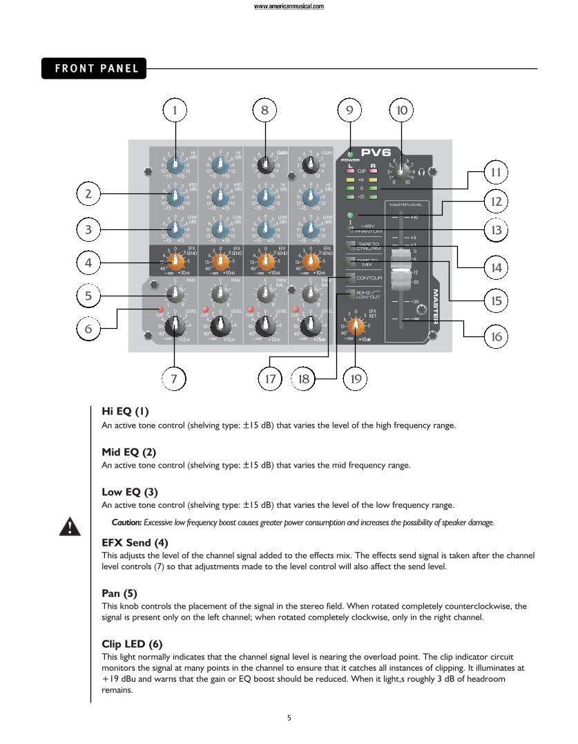
Hi EQ (1)An active tone control (shelving type: ±15 dB) that varies the level of the high frequency range.
Mid EQ (2)An active tone control (shelving type: ±15 dB) that varies the mid frequency range.
Low EQ (3)An active tone control (shelving type: ±15 dB) that varies the level of the low frequency range.
Caution: Excessive low frequency boost causes greater power consumption and increases the possibility of speaker damage.
EFX Send (4)This adjusts the level of the channel signal added to the effects mix. The effects send signal is taken after the channellevel controls (7) so that adjustments made to the level control will also affect the send level.
Pan (5)This knob controls the placement of the signal in the stereo field. When rotated completely counterclockwise‚ thesignal is present only on the left channel; when rotated completely clockwise‚ only in the right channel.
Clip LED (6)This light normally indicates that the channel signal level is nearing the overload point. The clip indicator circuitmonitors the signal at many points in the channel to ensure that it catches all instances of clipping. It illuminates at+19 dBu and warns that the gain or EQ boost should be reduced. When it light,s roughly 3 dB of headroomremains.
FF RR OO NN TT PP AA NN EE LL
1 8 9 10
2
3
4
5
6
7
11
12
13
14
15
16
17 18 19
6
Level (7)This is the channel output level control. The optimum setting is the 0 (unity gain) position.
Gain (8)This control establishes the nominal operating level for the channel. The input gain can be adjusted over a widerange to compensate for soft voices or very loud drums. To maximize the signal-to-noise ratio, the gain should beset to the proper level with the channel level control (7) set to 0. If the clip LED comes on and remains lit, tryreducing the gain.
Power LED (9)This LED indicates that AC power is supplied to the unit‚ the power switch is on and the unit is functioningproperly.
Headphone Level (10)This knob sets the headphone and control room output level. To avoid damage to your hearing‚ make sure to turnthe dial fully counterclockwise before using headphones. Slowly turn the knob clockwise until a comfortablelistening level is set. Normally, the signal in the headphones is the Left/Right signal. If the Tape to Control Room(14) is engaged‚ the tape signal is also included.
LED Meters (11)Two four-segment LED arrays are provided to monitor the levels of the main Left/Right outputs. These meters rangefrom -21 dB to +19 dB. A reading of 0 db on the meter corresponds to +4 dBu at the outputs.
Phantom Power LED (12)This LED lights when the Phantom Power Switch (13) has been engaged.
Phantom Power Switch (13)Applies +48 VDC Voltage to the input XLR connectors to power microphones requiring phantom power.
If phantom power is used, do not connect unbalanced dynamic microphones or other devices to the XLR inputs thatcannot handle this Voltage. The Phantom Power LED (12) indicates when phantom power is on.
Tape To Control Room (14)Depressing this switch adds the tape return to the Control Room and Headphone Outputs (24) for zero latency monitoring.
Tape to Mix (15)Depressing this switch routes the signal from the Tape Inputs to the Main Outputs (27).
Master Level Fader (16)The Master Fader controls the level sent to the main Left/Right outputs. Best results are obtained when this controlis set near the 0 point.
Contour Switch (17)Engaging this switch enhances the signal by adding both bass and treble frequencies. This is especially effective atlower volumes or for tape/CD playback.
80 Hz Low Cut (18)The Low Cut filter has a corner frequency of 80 Hz. When engaged‚ it can improve clarity by removing lowfrequencies that can make a mix sound muddy. This feature is especially useful when playing outside on a windy dayor on a hollow‚ noisy stage. These kinds of ambient noises can rob your sound system of power. Engaging thisswitch removes those frequencies from the system and restores power to where it’s needed.
EFX/Return (19)The EFX/Return Level Control adjusts the level sent to the Left/Right main bus from the return inputs.
7
RR EE AA RR PP AA NN EE LL
20
21
22
23 24 25 26
28 27
29 30 31 32
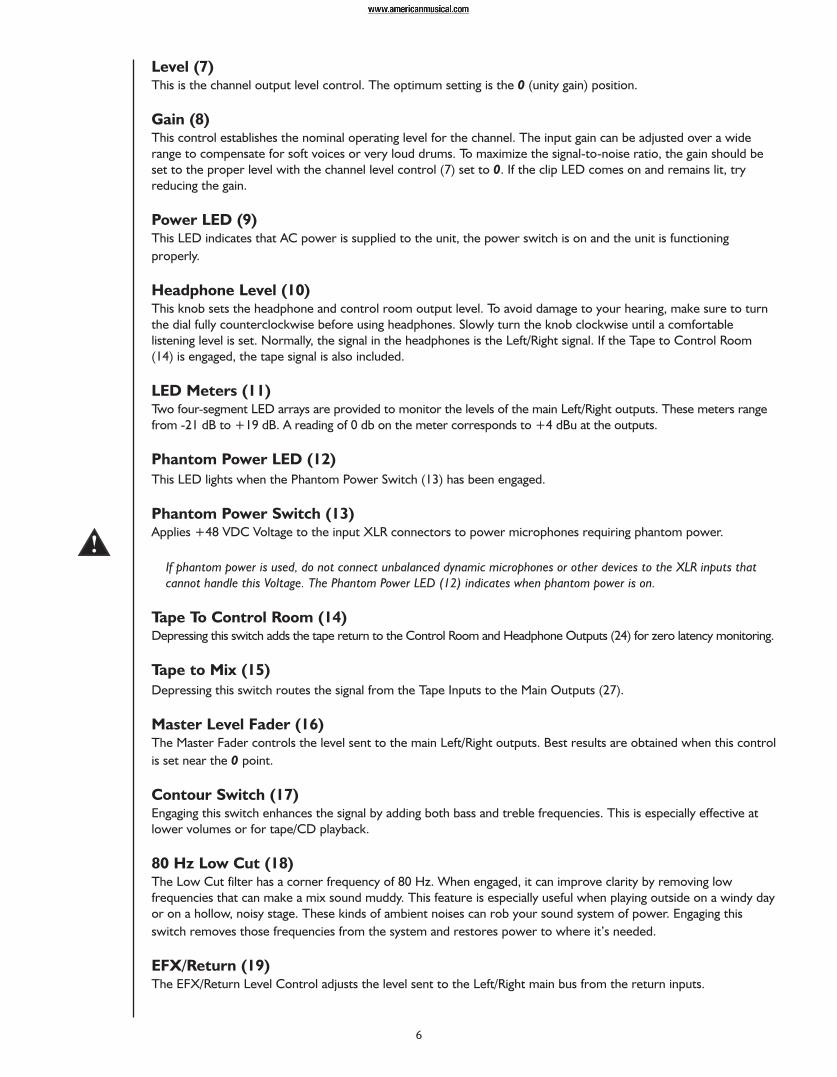
Mic (XLR) Inputs (20)XLR balanced inputs optimized for a microphone or other low impedance source. Pin 2 is the positive input.Because of the wide range of gain adjustment, signal levels up to +14 dBu can be accommodated.
Line (1⁄4") Inputs (21)1⁄4” balanced (TRS) 10 k Ohm impedance input. The tip is the positive input and should be used for unbalancedinputs. It has 20 dB less gain than the XLR input and does not have phantom power available. The Mic and Lineinputs should not be used simultaneously.
Gain (Channels 1 & 2) (22)This control establishes the nominal operating level for the channel. The input gain can be adjusted over a widerange to compensate for soft voices or very loud drums. To maximize the signal-to-noise ratio, the gain shouldbe set to the proper level with the channel level control (7) set to 0. If the Clip LED comes on and remains lit,try reducing the gain.
Stereo Inputs (23)Channels 3 and 4 feature stereo inputs via 1⁄4” inputs and mono XLR inputs. When the 1⁄4" line inputs are in use‚the XLR mic input is muted to prevent unwanted noise.
8
Control Room Outputs (24)The Control Room Outputs feature two 1⁄4" TRS Z-balanced jacks. These outputs can be used with Tip‚ Ring Sleeve(TRS) balanced or Tip Sleeve (TS) unbalanced connectors. The Control Room Output Level is adjusted with theHeadphone Level Control (10).
EFX Send (25)The EFX Send features a 1⁄4" TRS Z-balanced jack in the master section. These outputs can be used with Tip‚ RingSleeve (TRS) balanced or Tip Sleeve (TS) unbalanced connectors. The EFX mix is determined by the amount ofsignal being sent to the EFX bus in each channel.
Headphone Output (26)The Headphone Output is a 1⁄4" TRS (tip = left; ring = right; sleeve = ground). The signal sent to this output isnormally the Left/Right mix. When the Tape to Control Room switch is engaged‚ the tape input signal is added tothe Left/Right mix and can be monitored in the headphones.
Left/Right Outputs (27)The Left/Right Outputs feature two 1⁄4" TRS Z-balanced jacks. These outputs can be used with Tip‚ Ring, Sleeve(TRS) balanced or Tip, Sleeve (TS) unbalanced connectors.
EFX Return (28)The EFX Return inputs (Left/Mono‚ Right) feature two 1⁄4" TRS Z-balanced jacks. These outputs can be used withTip‚ Ring, Sleeve (TRS) balanced or Tip, Sleeve (TS) unbalanced connectors. The EFX Return is controlled via theEFX/Return Level Control (19).
Power Adapter Input (29)Use to connect the included power supply. Be sure the power supply is connected to the PV®6 before connectingto a power source. Use 16 VAC 1 A adapter only.
Power Switch (30)Depressing the power switch applies power to the unit.
Tape In/Out (32 & 31)The tape input jacks are designed to accommodate tape‚ CD or computer sound card output levels. The out level is+4 dBu for connection to a recorder or sound card input. The tape inputs can be used as an additional stereo inputby engaging the Tape to Main Mix switch (15). The tape input can also be used to monitor the recorder/sound cardoutput without the risk of feedback.
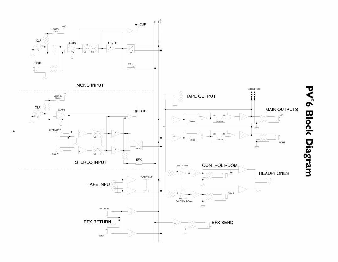
9
CONTOUR
LO HI
CONTOUR
LO HI
PAN
+48V
4
+-4
EQ
LO MID HI
+-
+-
+-
HI PASS
HI PASS
EQ
LO HI
EQ
LO HI
+48V
BALANCE
TAPE -L/R SELECT
POWERPHANTOMGLOBAL
POWERPHANTOM
RIGHT
LEFT
EFX
CLIPGAINXLR
EF
X
LINE
RIG
HT
LEF
T
XLRLEVELGAIN
EFX
CLIP
MONO INPUT
STEREO INPUT
EFX RETURN
LEFT/MONO
RIGHT
TAPE OUTPUT
HEADPHONES
CONTROL ROOM
TAPE TO MIX
LED METER
LEFT/MONO
RIGHT
LEFT
RIGHT
MAIN OUTPUTS
EFX SEND
TAPE INPUT
GLOBAL
CONTROL ROOMTAPE TO
2
3
1
2
3
1
PV
®6 Block D
iagram
10
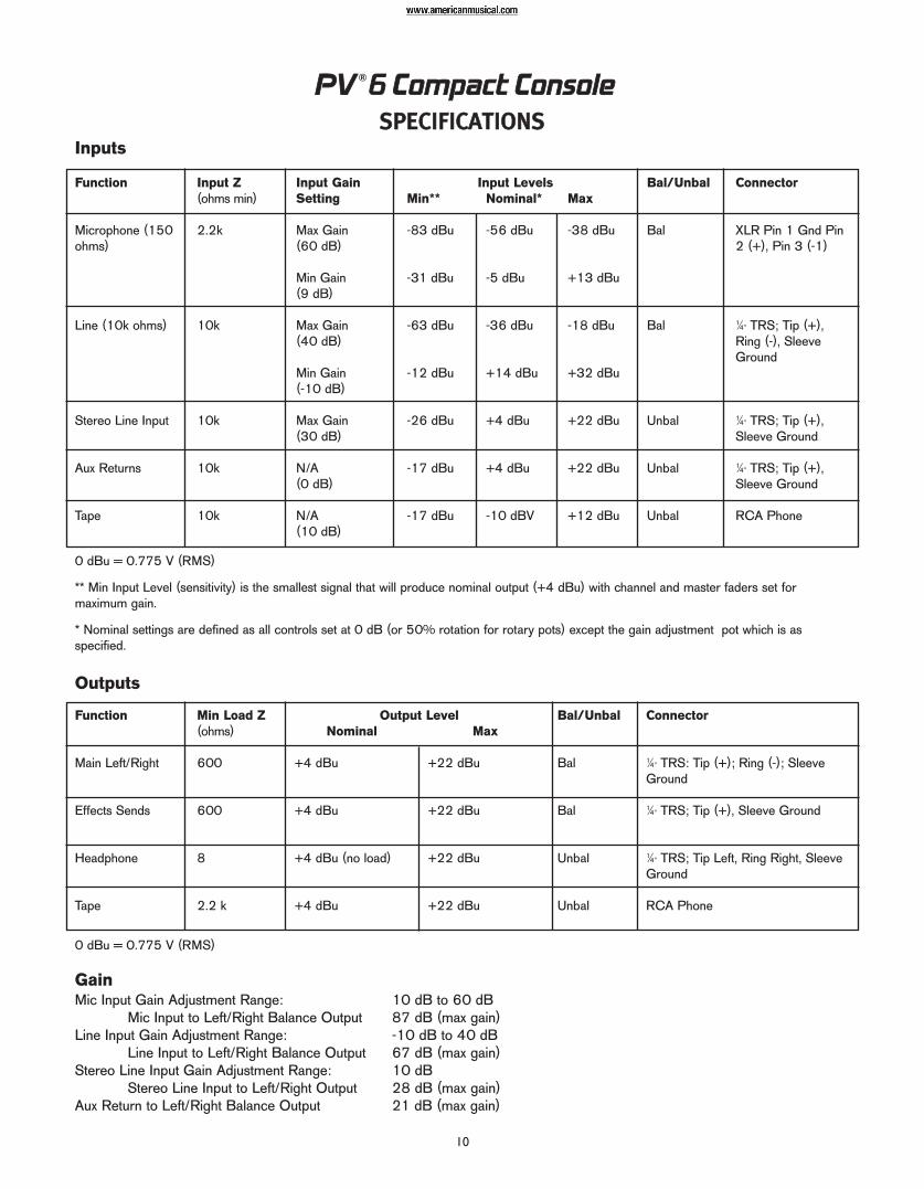
PPVV ®66 CCoommppaacctt CCoonnssoolleeSSPPEECCIIFFIICCAATTIIOONNSS
Function
Microphone (150ohms)
Line (10k ohms)
Stereo Line Input
Aux Returns
Tape
Input Z (ohms min)
2.2k
10k
10k
10k
10k
Input GainSetting
Max Gain (60 dB)
Min Gain (9 dB)
Max Gain (40 dB)
Min Gain (-10 dB)
Max Gain (30 dB)
N/A (0 dB)
N/A (10 dB)
Nominal*
-56 dBu
-5 dBu
-36 dBu
+14 dBu
+4 dBu
+4 dBu
-10 dBV
Max
-38 dBu
+13 dBu
-18 dBu
+32 dBu
+22 dBu
+22 dBu
+12 dBu
Bal/Unbal
Bal
Bal
Unbal
Unbal
Unbal
Connector
XLR Pin 1 Gnd Pin2 (+)‚ Pin 3 (-1)
1⁄4" TRS; Tip (+)‚Ring (-)‚ SleeveGround
1⁄4" TRS; Tip (+)‚Sleeve Ground
1⁄4" TRS; Tip (+)‚Sleeve Ground
RCA Phone
Input LevelsMin**
-83 dBu
-31 dBu
-63 dBu
-12 dBu
-26 dBu
-17 dBu
-17 dBu
Function
Main Left/Right
Effects Sends
Headphone
Tape
Min Load Z (ohms)
600
600
8
2.2 k
Nominal
+4 dBu
+4 dBu
+4 dBu (no load)
+4 dBu
Max
+22 dBu
+22 dBu
+22 dBu
+22 dBu
Bal/Unbal
Bal
Bal
Unbal
Unbal
Connector
1⁄4" TRS: Tip (+); Ring (-); SleeveGround
1⁄4" TRS; Tip (+)‚ Sleeve Ground
1⁄4" TRS; Tip Left‚ Ring Right‚ SleeveGround
RCA Phone
Output Level
0 dBu = 0.775 V (RMS)
** Min Input Level (sensitivity) is the smallest signal that will produce nominal output (+4 dBu) with channel and master faders set formaximum gain.
* Nominal settings are defined as all controls set at 0 dB (or 50% rotation for rotary pots) except the gain adjustment pot which is asspecified.
0 dBu = 0.775 V (RMS)
GainMic Input Gain Adjustment Range: 10 dB to 60 dB
Mic Input to Left/Right Balance Output 87 dB (max gain)Line Input Gain Adjustment Range: -10 dB to 40 dB
Line Input to Left/Right Balance Output 67 dB (max gain)Stereo Line Input Gain Adjustment Range: 10 dB
Stereo Line Input to Left/Right Output 28 dB (max gain)Aux Return to Left/Right Balance Output 21 dB (max gain)
Inputs
Outputs

11
Output
Master Left/Right
Effects Sends
Residual Noise
-98 dBu
-90 dBu
-84 dBu
-96 dBu
-84 dBu
S/N Ratio (ref. +4 dBu)
102 dB
94 dB
90 dB
100 dB
88 dB
Test Conditions
Master Fader Down‚ Channel Levels Down
Master Fader Nominal‚ Channel Levels Down
All controls nominal‚ mic gain minimum
All controls off
All channel sends nominal
(Hum and noise measurements: 22 Hz to 22 kHz BW)
Frequency ResponseMic Input to Left/Right Output 14 Hz to 25 kHz +0 dB/-1 dB
Total Harmonic Distortion<0.01% 20 Hz to 20 kHz Mic to Left/Right Output (10 Hz to 80 kHz BW)<0.005% Typical
Equivalent Input Noise (EIN)-129 dBu (input terminated with 150 ohms)
Crosstalk>80 dB Adjacent Input Channels (1 kHz)>75 dB Left to Right Outputs (1 kHz)
Common Mode Rejection Ratio (Mic Input)50 dB minimum (20 Hz to 20 kHz)70 dB typical @ 1 kHz
Meters4-segment‚ peak reading (0 dB = +4 dBu)
Signal/Overload IndicatorsRed LED lights 3 dB below clipping
Dimensions7.55" (19.18 cm) wide x 9.717" (24.68 cm) deep x 2.7" (6.86 cm) high
WeightWithout power supply: 3.9 lbs (1.77 kg)With power supply: 5.1 lbs (2.31 kg)
Power RequirementsDomestic: 16.5 VAC 60 Hz; 8 watts nominal
Hum and Noise

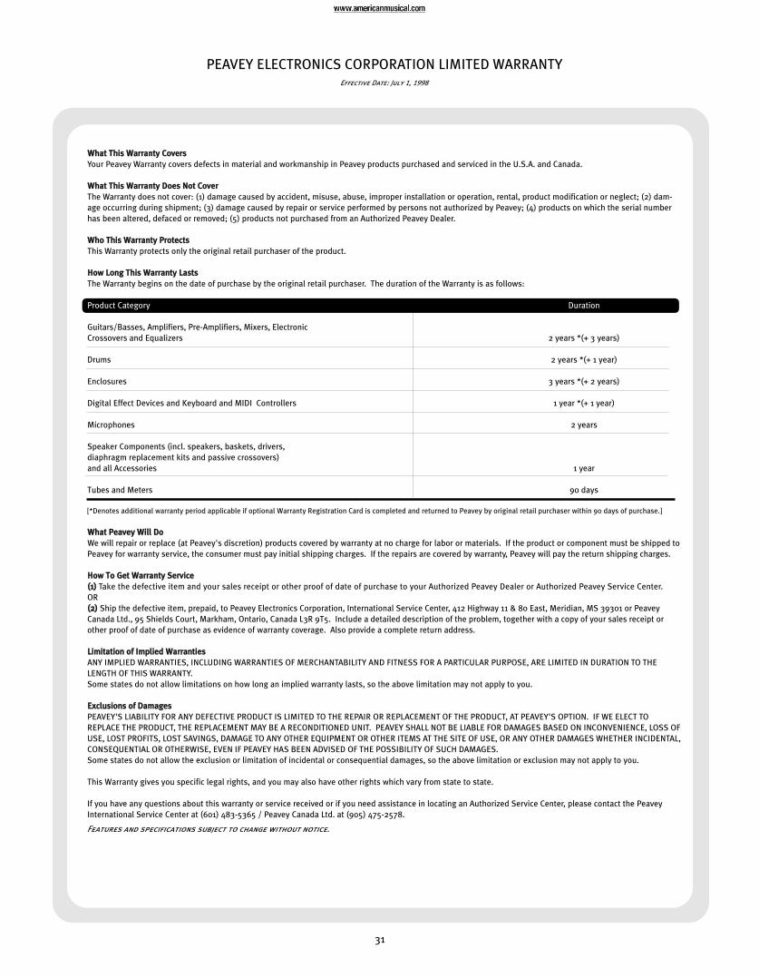
31
PEAVEY ELECTRONICS CORPORATION LIMITED WARRANTYEffective Date: July 1, 1998
WWhhaatt TThhiiss WWaarrrraannttyy CCoovveerrssYour Peavey Warranty covers defects in material and workmanship in Peavey products purchased and serviced in the U.S.A. and Canada.
WWhhaatt TThhiiss WWaarrrraannttyy DDooeess NNoott CCoovveerrThe Warranty does not cover: (1) damage caused by accident, misuse, abuse, improper installation or operation, rental, product modification or neglect; (2) dam-age occurring during shipment; (3) damage caused by repair or service performed by persons not authorized by Peavey; (4) products on which the serial numberhas been altered, defaced or removed; (5) products not purchased from an Authorized Peavey Dealer.
WWhhoo TThhiiss WWaarrrraannttyy PPrrootteeccttssThis Warranty protects only the original retail purchaser of the product.
HHooww LLoonngg TThhiiss WWaarrrraannttyy LLaassttssThe Warranty begins on the date of purchase by the original retail purchaser. The duration of the Warranty is as follows:
Product Category Duration
Guitars/Basses, Amplifiers, Pre-Amplifiers, Mixers, Electronic Crossovers and Equalizers 2 years *(+ 3 years)
Drums 2 years *(+ 1 year)
Enclosures 3 years *(+ 2 years)
Digital Effect Devices and Keyboard and MIDI Controllers 1 year *(+ 1 year)
Microphones 2 years
Speaker Components (incl. speakers, baskets, drivers, diaphragm replacement kits and passive crossovers) and all Accessories 1 year
Tubes and Meters 90 days
[*Denotes additional warranty period applicable if optional Warranty Registration Card is completed and returned to Peavey by original retail purchaser within 90 days of purchase.]
WWhhaatt PPeeaavveeyy WWiillll DDooWe will repair or replace (at Peavey's discretion) products covered by warranty at no charge for labor or materials. If the product or component must be shipped toPeavey for warranty service, the consumer must pay initial shipping charges. If the repairs are covered by warranty, Peavey will pay the return shipping charges.
HHooww TToo GGeett WWaarrrraannttyy SSeerrvviiccee((11)) Take the defective item and your sales receipt or other proof of date of purchase to your Authorized Peavey Dealer or Authorized Peavey Service Center. OR((22)) Ship the defective item, prepaid, to Peavey Electronics Corporation, International Service Center, 412 Highway 11 & 80 East, Meridian, MS 39301 or PeaveyCanada Ltd., 95 Shields Court, Markham, Ontario, Canada L3R 9T5. Include a detailed description of the problem, together with a copy of your sales receipt orother proof of date of purchase as evidence of warranty coverage. Also provide a complete return address.
LLiimmiittaattiioonn ooff IImmpplliieedd WWaarrrraannttiieessANY IMPLIED WARRANTIES, INCLUDING WARRANTIES OF MERCHANTABILITY AND FITNESS FOR A PARTICULAR PURPOSE, ARE LIMITED IN DURATION TO THELENGTH OF THIS WARRANTY. Some states do not allow limitations on how long an implied warranty lasts, so the above limitation may not apply to you.
EExxcclluussiioonnss ooff DDaammaaggeessPEAVEY'S LIABILITY FOR ANY DEFECTIVE PRODUCT IS LIMITED TO THE REPAIR OR REPLACEMENT OF THE PRODUCT, AT PEAVEY'S OPTION. IF WE ELECT TOREPLACE THE PRODUCT, THE REPLACEMENT MAY BE A RECONDITIONED UNIT. PEAVEY SHALL NOT BE LIABLE FOR DAMAGES BASED ON INCONVENIENCE, LOSS OFUSE, LOST PROFITS, LOST SAVINGS, DAMAGE TO ANY OTHER EQUIPMENT OR OTHER ITEMS AT THE SITE OF USE, OR ANY OTHER DAMAGES WHETHER INCIDENTAL,CONSEQUENTIAL OR OTHERWISE, EVEN IF PEAVEY HAS BEEN ADVISED OF THE POSSIBILITY OF SUCH DAMAGES.Some states do not allow the exclusion or limitation of incidental or consequential damages, so the above limitation or exclusion may not apply to you.
This Warranty gives you specific legal rights, and you may also have other rights which vary from state to state.
If you have any questions about this warranty or service received or if you need assistance in locating an Authorized Service Center, please contact the PeaveyInternational Service Center at (601) 483-5365 / Peavey Canada Ltd. at (905) 475-2578.
Features and specifications subject to change without notice.

Features and specifications subject to change without notice.
Peavey Electronics Corporation • 711 A Street • Meridian • MS • 39301
(601) 483-5365 • FAX (601) 486-1278 • www.peavey.com
©2004 Printed in the U.S.A. 2/04