quadrant product guide br e 0114
TRANSCRIPT
Engineering Plastics
You inspire ... we materialize®
Product Guide for Design Engineers

Quadrant history:The fi rst engineering polymer shapes for machining.
Quadrant today:The broadest range of engineering polymer shapes allowing the most effective material choice.
Quadrant tomorrow:New products for new needs, developed by QEPP’s global product and application development team.
For over 60 years, the companies that today form Quadrant have been developing new materials to meet changing demands of customers around the world. The innovative, collaborative spirit between our people and our customers has shaped our success and led to the industry’s broadest range of engineering plastic shapes for machining. Our investment in innovation will only increase in the years ahead, to support your requirements for higher levels of performance, productivity and value.
2
Quadrant Engineering Plastics Global Scope
You inspire ... we materialize®

Up
to 3
10 °
C
3
Material Selection & Design Guidelines 6Classifi cation of Plastics 14
Advanced Engineering Plastics for Elevated Temperature Range | up to 310 °CDuratron® PBI 16Duratron® PI 17Duratron® PAI 18Ketron® PEEK 19Techtron® PPS 21Key Features of Bearing Grades 22Quadrant® PPSU 23Quadrant® 1000 PSU 24Food Contact Compliance Status of Advanced Engineering Plastics 25Duratron® PEI 26Symalit® 1000 PVDF 27Symalit® 1000 ECTFE 28Symalit® 1000 PFA 29Fluorosint® 30Semitron® ESd 32
Technical Specifi cation of Advanced Engineering PlasticsThermal Expansion [CLTE] 34Dimensional Stability 35Modulus of Elasticity 36Deformation under Load 38Min./Max. Service Temperature 39Temperature of Defl ection 40Stress Relaxation 40Wear Resistance 42Dynamic Coeffi cient of Friction 43 Pressure Velocity [PV] Values 44
Content

4
General Engineering Plastics for Medium Temperature Range | up to 120 °CErtalon® | Nylatron® 46Ertacetal® | Acetron® MD 49Food Contact Compliance Status of General Engineering Plastics 51Ertalyte® 52Quadrant® 1000 PC 53
Technical Specifi cation of General Engineering PlasticsChemical Resistance 54Dimensional Stability 54Modulus of Elasticity 55Compressive Stress 55Min./Max. Service Temperature 56Stress Relaxation 57Wear Resistance 57Dynamic Coeffi cient of Friction 58Pressure Velocity [PV] Values 59
Polyethylene Grades for Low Temperature Range | up to 85 - 110 °CTIVAR® 1000 PE-UHMW Standard Grades 60TIVAR® PE-UHMW Speciality Grades 61Borotron® PE-[U]HMW 63PE 500 PE-HMW 64
Polyethylene Selection Table 64Food Contact Compliance Status of PE-[U]HMW Plastics 65
Up
to 1
20 °
CU
p to
85
- 11
0 °C
Content

5
Technical Specifi cation of Polyethylene GradesTensile Stress 66Stiffness 67Impact Strength [Charpy] 67Thermal Expansion 68Tensile Creep Behaviour 68Abrasion Resistance 69Wear Resistance 70Dynamic Coeffi cient of Friction 71
Life Science Grades [LSG] 72Products for the Life Science Industry
Physical Properties 74Production Capabilities 86
Edition December 2011
Content

Plastics are increasingly being used to replace other materials like bronze, stainless steel, aluminum and ceramics. The most popular reasons for switching to plastics include:
Longer part life Elimination of lubrication Reduced wear on mating parts Lower density and hence lower inertia forces Better mechanical dampening [less noise] Faster operation of equipment [higher line speeds] Less power needed to run equipment Chemical and corrosion resistance and inertness
With the many plastic materials available today, selecting the best one can be an intimidating proposition. Here are guidelines to assist those less familiar with these plastics.
Determine whether the component is a “bearing and wear application” [a load bearing part subject to a relative movement and hence frictional forces] or a “structural application” [only subject to a static or dynamic load].
Determining the primary function of the fi nished component will direct you to a group of materials. For example, semi-crystalline materials [i.e., nylon, acetal] outperform amorphous materials [i.e., polycarbonate, polysulfone, polyetherimide or polyphenylene sulfone] in bearing and wear applications. Within the material groups, you can further reduce your choices by knowing what additives are best suited to your application:
Wear properties are enhanced by MoS2, graphite, carbon fi ber and polymeric lubricants [i.e., PTFE, waxes]. Structural properties [strength and stiffness] are enhanced by glass fi bre and carbon fi bre.
Once you have determined the nature of the application [wear or structural], you can further reduce your material choices by determining the application‘s mechanical property requirements. For bearing and wear applications, the fi rst consideration is the load bearing capability [allowable bearing pressure and/or PV-value] and wear performance [wear factor].Calculate the PV-value of your specifi c application [pressure [MPa] x sliding velocity (m/s)]. Using Figure 1 or another similar one from the Quadrant literature, select materials whose limiting PV-value is above the PV-value you have calculated for your specifi c application. Further selection can be made by considering the “wear factors” of your material choices. The lower the “wear factor”, the longer the material is expected to last.
6
Step 1
Effective Selection & Design Techniques

2
1,75
1,5
1,25
1
0,75
0,5
0,25
0
100
75
50
25
0
Wea
r fa
ctor
[µm
/km
]
Lim
iting
PV-
valu
e [M
Pa.
m/s
]
Tech
tron
® P
PS
Ert
acet
al®
C
Ket
ron®
100
0 P
EE
K
Ert
alon
® 6
6 S
A
Dur
atro
n® D
7000
PI
Fluo
rosi
nt®
500
Ert
alon
® 6
PLA
Nyl
atro
n® G
SM
TIVA
R®
100
0
Tech
tron
® H
PV
PP
S
Fluo
rosi
nt®
207
Nyl
atro
n® N
SM
Dur
atro
n® C
U60
PB
I
Fluo
rosi
nt®
HP
V
Nyl
atro
n® 7
03 X
L
Ket
ron®
HP
V P
EE
K
Ert
alyt
e® T
X
Dur
atro
n® T
4301
PA
I
Wear factorLimiting PV-value for a sliding velocity of 0.1 m/s
LOWER IS BETTER HIGHER IS BETTER
[*]: for details on the values given above see pages 42, 44, 57 and 59
Fig. 1: Wear Resistance and Pressure Velocity Capability [*]
STRESS [] STRAIN [] = CONSTANT [E]
Structural components are often designed for maximum continuous stresses equal to 25 % of their tensile strength at a specifi c temperature. In case of statically loaded components, this guideline compensates for the viscoelastic behaviour of plastics that result in creep.
Most materials - including metals and plastics - when subjected to loads, show a deformation that is proportional to the imposed loads over at least a range of loads. Since stress [] is proportional to load and strain [] is proportional to deformation, this also implies that stress is proportional to strain. Hooke‘s law is the statement of that proportionality:
The constant [E] is called the modulus of elasticity [also known as `Young‘s modulus‘] and it is an indicator of material stiffness. In the plastics industry we generally apply here the modulus of elasticity as derived from a short-term tension test. The point at which a material ceases to obey Hooke‘s law is known as its proportional limit.
Strains below 1 % remain within the elastic limits of most engineering plastics and therefore generally allow analysis based upon the assumption that the material is linearly elastic [obeys Hooke‘s law], homogeneous and isotropic.
7
Effective Selection & Design Techniques
1 1000 1000010010 100000
5
4
3
2
1
0
[*]: based on raw material supplier data
0.1
Loading time [h]
Str
ain
[%]
10 MPa15 MPa20 MPa25 MPa30 MPa35 MPa
1
2
3
4
6
5
1 - 6 : different stress levels
1 1000 1000010010 1000000.1
Loading time [h]
40
30
20
10
0
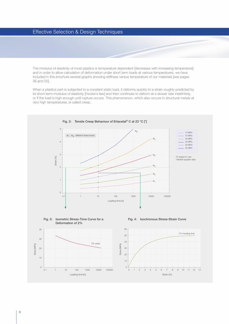
Fig. 3: Isometric Stress-Time Curve for a Deformation of 2%
Fig. 4: Isochronous Stress-Strain Curve
60
50
40
30
20
10
0
Strain [%]
0
Str
ess
[MP
a]
Str
ess
[MP
a]
121110987654321 13
Fig. 2: Tensile Creep Behaviour of Ertacetal® C at 23 °C [*]
2% strain
10 h loading time
8
The modulus of elasticity of most plastics is temperature dependent [decreases with increasing temperature] and in order to allow calculation of deformation under short term loads at various temperatures, we have included in this brochure several graphs showing stiffness versus temperature of our materials [see pages 36 and 55].
When a plastics part is subjected to a constant static load, it deforms quickly to a strain roughly predicted by its short-term modulus of elasticity [Hooke‘s law] and then continues to deform at a slower rate indefi nitely, or if the load is high enough until rupture occurs. This phenomenon, which also occurs in structural metals at very high temperatures, is called creep.
Effective Selection & Design Techniques
1 h10 h100 h1000 h10000 h
10 h loading time
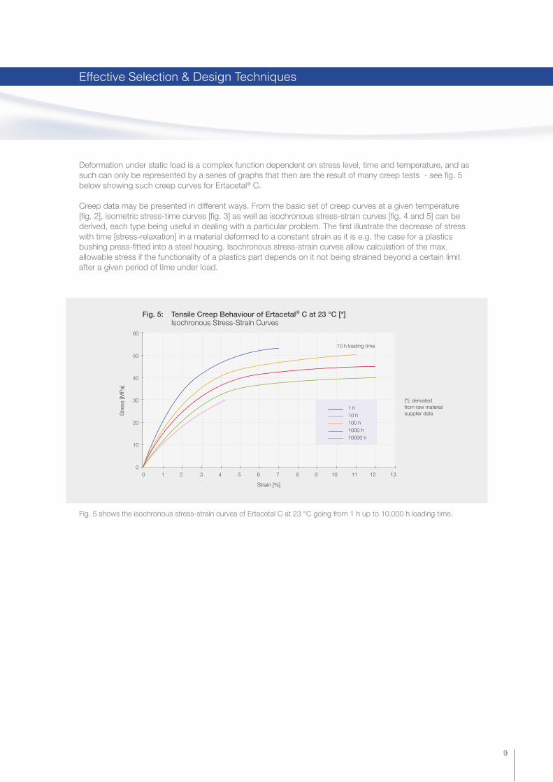
Fig. 5: Tensile Creep Behaviour of Ertacetal® C at 23 °C [*] Isochronous Stress-Strain Curves
60
50
40
30
20
10
0
Str
ess
[MP
a]
[*]: derivated from raw material supplier data
Strain [%]
0 121110987654321 13
Fig. 5 shows the isochronous stress-strain curves of Ertacetal C at 23 °C going from 1 h up to 10.000 h loading time.
9
Deformation under static load is a complex function dependent on stress level, time and temperature, and as such can only be represented by a series of graphs that then are the result of many creep tests - see fi g. 5 below showing such creep curves for Ertacetal® C.
Creep data may be presented in different ways. From the basic set of creep curves at a given temperature [fi g. 2], isometric stress-time curves [fi g. 3] as well as isochronous stress-strain curves [fi g. 4 and 5] can be derived, each type being useful in dealing with a particular problem. The fi rst illustrate the decrease of stress with time [stress-relaxation] in a material deformed to a constant strain as it is e.g. the case for a plastics bushing press-fi tted into a steel housing. Isochronous stress-strain curves allow calculation of the max. allowable stress if the functionality of a plastics part depends on it not being strained beyond a certain limit after a given period of time under load.
Effective Selection & Design Techniques

Fig. 6: Examples of Thermal Performance
450° C400°350°300°250°200°150°100°50°0
Ert
alon
® 6
6SA
Nyl
atro
n® N
SM
Ert
acet
al®
C
Ert
alyt
e®
Fluo
rosi
nt®
500
Qua
dran
t® P
PS
U
Tech
tron
® H
PV
PP
S
Ket
ron®
100
0 P
EE
K
Dur
atro
n® T
4203
PA
I
Dur
atro
n® C
U60
PB
I
C 450°400°350°300°250°200°150°100°50°
0
Tem
pera
ture
of d
efl e
ctio
n un
der
load
ac
c. to
IS
O 7
5/M
etho
d A
: 1.8
MP
a [°
C]
Max
. allo
wab
le s
ervi
ce te
mpe
ratu
re in
air
cont
inuo
usly
for
min
. 20.
000
h [°
C]
Consider the thermal requirements of your application using both typical and extreme operating conditions.
A thermoplastic material’s temperature resistance is broadly characterised by both its ‘temperature of defl ection under load’ and its ‘max. continuously allowable service temperature’.The ‘temperature of defl ection under load’, formerly called ‘Heat Defl ection Temperature [HDT]’, is related to a certain level of stiffness at elevated temperature and it is often considered as the max. temperature limit for moderately to highly stressed, unconstrained components.
The ‘max. continuously allowable service temperature’ is generally reported as the temperature above which signifi cant, permanent physical property degradation occurs after long term exposure. Depending on the environment [air, oil, …], the property considered, the degradation criterion used and the exposure time taken into consideration, there can be several max. allowable service temperatures for one and the same material. As such we can e.g. have the temperature at which there is a decrease in tensile strength of 50 % [measured at 23 °C] as compared with the original value after 20.000 hours of exposure to hot air, the temperature at which there is a decrease in impact strength of 50 % [measured at 23 °C] as compared with the original value after 10.000 hours of exposure to hot oil.
The melting point of semi-crystalline plastic materials and the glass transition temperature of amorphous ones are the short-term temperature extremes to which form stability is maintained. For most engineering plastics, using them at or above these temperatures is to be avoided.
Note, however, that the maximum allowable service temperature depends in many cases essentially on the duration and the magnitude of the mechanical stresses to which the material is subjected i.e. on the max. deformation one can allow in a given application [see fi g. 6].
10
Effective Selection & Design Techniques
Step 2

Fig. 7: Temperature/Chemical Resistance Positioning
Tem
pera
ture
of d
efl e
ctio
n un
der
load
acc
. to
ISO
75/
Met
hod
A: 1
.8 M
Pa
[°C
]
450
400
350
300
250
200
150
100
50
0
Low HighMediumChemical Resistance
Imidized AEP
Reinforced Semi-Crystalline AEP
GEP + Amorphous AEP Unreinforced Semi-Crystalline AEP
Duratron® PBIDuratron® PIDuratron® PAI
Ketron® CA30 PEEKKetron® GF30 PEEK
Ketron® 1000 PEEKTechtron® PPSFluorosint®
Quadrant® PPSUDuratron® PEIErtacetal®
Ertalon® 66 SA
11
Consider chemical exposure during use and cleaning.
In many of its brochures, Quadrant provides chemical compatibility information as a guideline, although it can be diffi cult to predict since concentration and temperature of the chemical reagent, exposure time and stress level in the plastics part each are major infl uencing factors in defi ning suitability for use.Ertalon®/Nylatron®, Ertacetal® and Ertalyte® are generally suitable for many industrial environments. Semicrystalline high performance materials such as Fluorosint®, Techtron® PPS and Ketron® PEEK are more suitable for aggressive chemical environments [see fi g. 7].Plenty of indicative chemical resistance data can be found on our website. However, we strongly recommend preliminary testing on a prototype under end-use conditions to determine the fi nal suitability of a selected plastics material for a given application.
Effective Selection & Design Techniques
Step 3

Note:
Once a plastics material selected, please keep in mind that physical property differences may occur depending upon the processing technique used to make the shape. For example:
Injection moulded parts generally exhibit greater anisotropy [properties are directionally dependent] than extruded products and they can also show a lower wear resistance [dependent on the degree of crystallinity which is function of the thermal history].
Compression moulded products are more isotropic [equal properties in all directions].
For Choose
Long lengths ExtrusionSmaller sectionsRod, plate and tube
Large stock shapes [heavy sections] CastingRod, plate and tubeNear net shapesCustom cast parts
Various shapes in advanced engineering materials CompressionRod, disc, plate and tube moulding
Small shapes and thin walls in advanced engineering materials InjectionHigh volumes [>10.000 parts] moulding
Before proceeding to steps 5-7, it may be appropriate to consider additional material characteristics including relative impact strength and toughness, dimensional stability and regulatory/agency compliance.
Materials showing higher tensile strain at break and impact strength [notched and unnotched] show higher toughness and lower notch sensitivity and are hence more suited for applications involving shock loading [see the property tables further in this brochure].
Engineering plastics can expand and contract with temperature changes 2 to 20 times more than steel. The coeffi cient of linear thermal expansion [CLTE] – itself being function of temperature as e.g. shown on pages 34 and 56. [CLTE increases with increasing temperature] – is used to estimate the expansion rate of plastic parts. CLTE values are given as average values within different temperature ranges in the property tables further in this book.
Water absorption also infl uences the dimensional stability since it causes swelling, and this effect is particularly pronounced in the case of nylon 6 and 66. The effects of environmental humidity and also temperature fl uctuations must be refl ected in the part design with respect to fi ts, assemblies and machining tolerances.
It is often required to confi rm compliance with governmental or other agency requirements with respect to food contact [i.e. the European Directive 2002/72/EC, the US Food and Drug Administration food additive regulations], contact with potable water [i.e. NSF, WRAS, ACS], use in dairy equipment [i.e. 3-A Dairy], fl ammability [i.e. UL 94], etc. Please check our website or consult us for the most current information and statements on these topics.
Select the most cost-effective shape for your part.
Quadrant offers designers the broadest size and confi guration availability. Be sure to investigate all of the shape possibilities, allowing you to reduce your fabrication costs by obtaining the most economical shape. Consider Quadrant’s many processing alternatives.
12
STEP 5
Effective Selection & Design Techniques
Step 4
Step 5
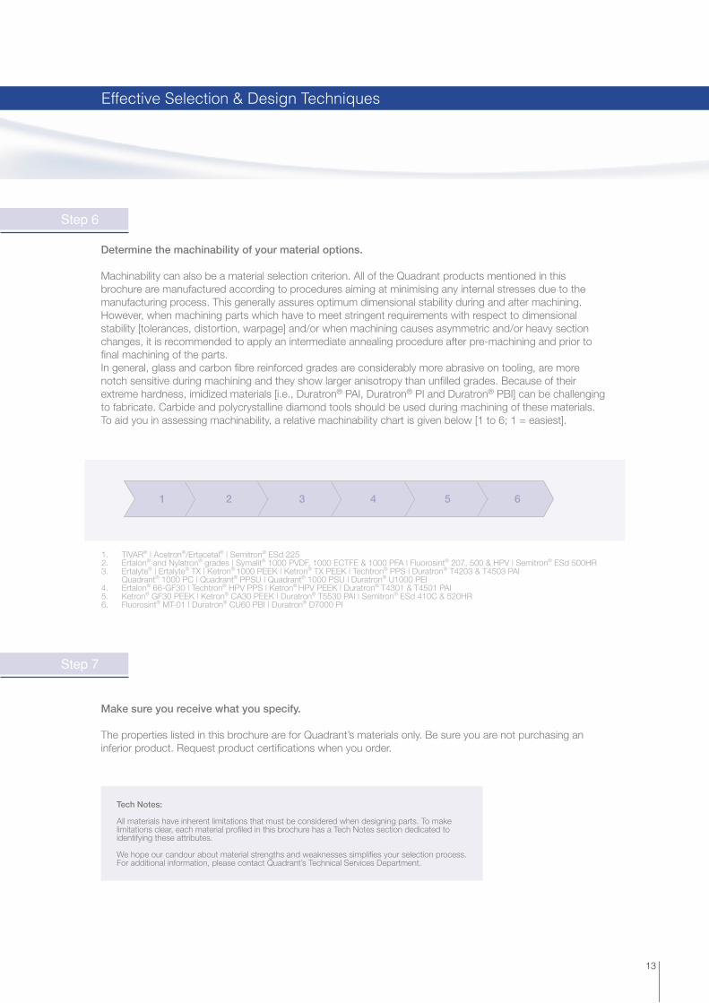
1 2 3 4 5 6
1. TIVAR® | Acetron®/Ertacetal® | Semitron® ESd 2252. Ertalon® and Nylatron® grades | Symalit® 1000 PVDF, 1000 ECTFE & 1000 PFA | Fluorosint® 207, 500 & HPV | Semitron® ESd 500HR 3. Ertalyte® | Ertalyte® TX | Ketron® 1000 PEEK | Ketron® TX PEEK | Techtron® PPS | Duratron® T4203 & T4503 PAI Quadrant® 1000 PC | Quadrant® PPSU | Quadrant® 1000 PSU | Duratron® U1000 PEI4. Ertalon® 66-GF30 | Techtron® HPV PPS | Ketron® HPV PEEK | Duratron® T4301 & T4501 PAI5. Ketron® GF30 PEEK | Ketron® CA30 PEEK | Duratron® T5530 PAI | Semitron® ESd 410C & 520HR6. Fluorosint® MT-01 | Duratron® CU60 PBI | Duratron® D7000 PI
Tech Notes:
All materials have inherent limitations that must be considered when designing parts. To make limitations clear, each material profi led in this brochure has a Tech Notes section dedicated to identifying these attributes.
We hope our candour about material strengths and weaknesses simplifi es your selection process. For additional information, please contact Quadrant’s Technical Services Department.
13
Determine the machinability of your material options.
Machinability can also be a material selection criterion. All of the Quadrant products mentioned in this brochure are manufactured according to procedures aiming at minimising any internal stresses due to the manufacturing process. This generally assures optimum dimensional stability during and after machining. However, when machining parts which have to meet stringent requirements with respect to dimensional stability [tolerances, distortion, warpage] and/or when machining causes asymmetric and/or heavy section changes, it is recommended to apply an intermediate annealing procedure after pre-machining and prior to fi nal machining of the parts.In general, glass and carbon fi bre reinforced grades are considerably more abrasive on tooling, are more notch sensitive during machining and they show larger anisotropy than unfi lled grades. Because of their extreme hardness, imidized materials [i.e., Duratron® PAI, Duratron® PI and Duratron® PBI] can be challenging to fabricate. Carbide and polycrystalline diamond tools should be used during machining of these materials. To aid you in assessing machinability, a relative machinability chart is given below [1 to 6; 1 = easiest].
Make sure you receive what you specify.
The properties listed in this brochure are for Quadrant’s materials only. Be sure you are not purchasing an inferior product. Request product certifi cations when you order.
Effective Selection & Design Techniques
Step 6
Step 7

PMMAABS
PSPVC
Duratron® PBIDuratron® PI
Amorphous
230 °C [450 °F]
120 °C [250 °F]
65 °C [150 °F]
Semi CrystallinePE
RF
OR
MA
NC
E [T
HE
RM
AL,
CH
EM
ICA
L, S
TR
EN
GT
H]
Semitron® ESd 480,490,500 HRKetron® PEEKTechtron® PPSFluorosint® PTFE Symalit® PVDF, ECTFE, FEP
Ertalyte® PET-PSemiton® ESd 225Nylatron® / Ertalon® PAAcetron® / Ertacetal® POMTIVAR® UHMW-PE
Sanalite® PPSanalite® HDPE/PPPE 500
Duratron® PAISemitron® ESd 520HR
Semitron® ESd 410CDuratron® PEI
Quadrant® PPSUQuadrant® PSU
Quadrant® PCQuadrant® PPO
14
The materials performance pyramid ranks the most common thermoplastics according to their temperature performance. Amongst these materials, different “families” can be recognised, all exhibiting high value in use within numerous applications.
Classifi cation of Plastics

15
Semi-crystalline Ertalon®/Nylatron® grades offer good mechanical strength and stiffness, high toughness, low friction and very good wear resistance. These properties make them ideal replacements for a wide variety of materials from metal to rubber.
Ertacetal® provides high mechanical strength and stiffness coupled with enhanced dimensional stability. As a semi-crystalline material, Ertacetal is characterised by a low coeffi cient of friction and good wear properties.
Unreinforced, semi-crystalline Ertalyte® offers very good dimensional stability in combination with excellent wear resistance, low friction, high strength, creep resistance and resistance to moderate acidic solutions.
Although exhibiting considerably lower mechanical strength, stiffness and creep resistance than Ertalon/Nylatron, Ertacetal and Ertalyte, the range of TIVAR® grades meets the demands of many industries and this from cryogenic temperatures up to about 85 °C. These materials show outstanding impact strength, excellent wear and abrasion resistance, low friction and excellent release properties.
Duratron® PBI, Duratron® PI and Duratron® PAI are designed for top performance in both structural and friction & wear applications! Characterised by an extreme temperature resistance [up to 310 °C continuously for Duratron PBI], these materials perform where others would fail.
The semi-crystalline Ketron® PEEK, Techtron® PPS, Fluorosint® and Symalit® PVDF typically offer a combination of excellent chemical and mechanical properties, also at elevated temperatures. These materials can be used for both structural and friction & wear applications. Symalit ECTFE and particularly Symalit PFA exhibit an excellent chemical and heat resistance combined with remarkable electrical insulating and dielectric properties.
The amorphous Quadrant® PPSU, Quadrant® PSU and Duratron® PEI exhibit an outstanding retention of their mechanical properties up to the glass transition temperature and excellent electrical properties. Additionally, their hydrolysis resistance [autoclavability] offer great possibilities for structural parts in medical, pharmaceutical and dairy industries.
From Semitron® ESd 225 – a static dissipative acetal grade – up to Semitron® ESd 520HR – a static dissipative polyamide-imide grade – six Semitron ESd grades are available to service static dissipative needs over a broad range of temperatures and mechanical loading conditions.
Classifi cation of Plastics

16
Duratron CU60 PBI is the highest performance engineering thermoplastic available today. Thanks to its unique property profi le, Duratron CU60 PBI might bring the ultimate solution when no other plastics material can.
Main Characteristics
Extremely high maximum allowable service temperature in air [310 °C continuously, up to 500 °C for short periods of time] Excellent retention of mechanical strength, stiffness and creep resistance over a wide temperature range Excellent wear and frictional behaviour Extremely low coeffi cient of linear thermal expansion Excellent resistance against high energy radiation [gamma- and X-rays] Inherent low fl ammability High purity in terms of ionic contamination Good electrical insulating and dielectric properties
Grades
Duratron® CU60 PBI [PBI; colour black]Duratron CU60 PBI offers the highest temperature resistance and best mechanical property retention over 200 °C of all unfi lled thermoplastics. Duratron CU60 PBI is very “clean” in terms of ionic impurity and does not outgas [except water]. These characteristics make this material extremely attractive to high-tech industries such as semiconductor and aerospace industries.
Usually Duratron CU60 PBI is used in critical components to decrease maintenance costs and to gain valuable production “uptime”. It is used to replace metals and ceramics in pump components, valve seats [high tech valves], bearings, rollers, high temperature insulators.
Tech Notes:
High tolerance fabricated components should be stored in sealed containers [usually polybags with desiccant] to avoid dimensional changes due to moisture absorption. Components rapidly exposed to temperatures above 200 °C should be “dried” prior to use or kept dry to avoid deformation from thermal shock.
Duratron® CU60 PBI Polybenzimidazole [PBI]
Advanced Engineering Plastics for Elevated Temperature Range
17
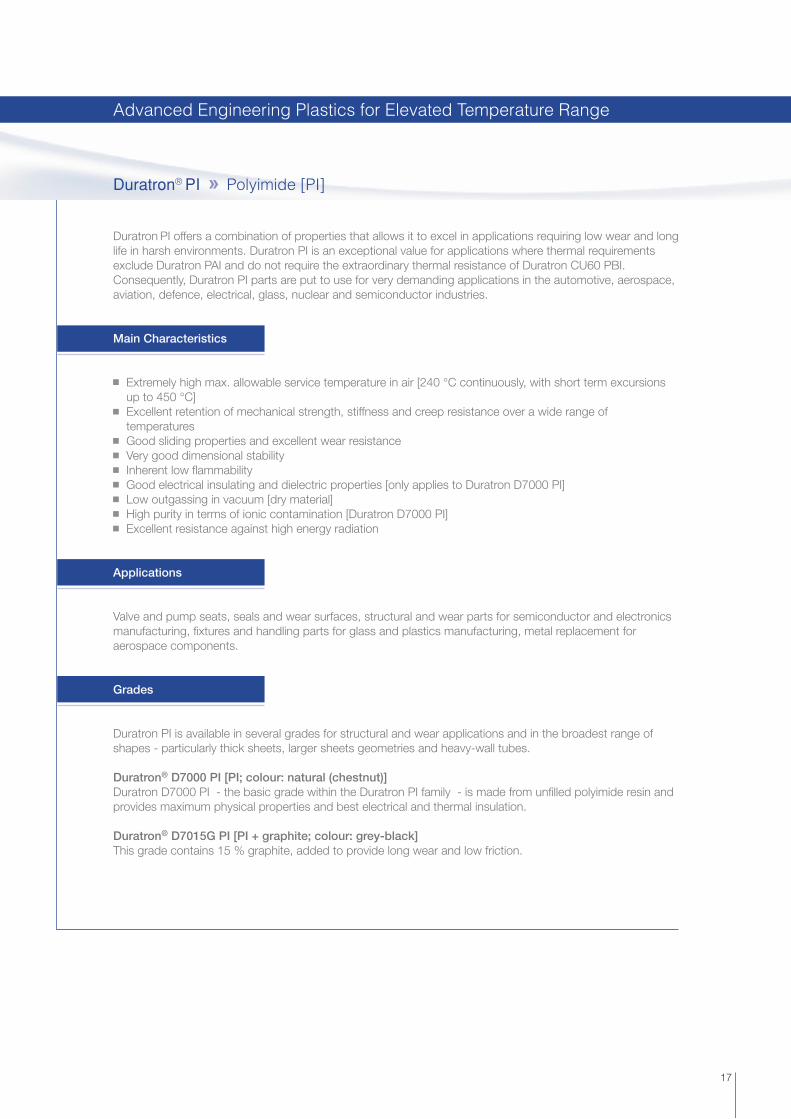
Duratron PI offers a combination of properties that allows it to excel in applications requiring low wear and long life in harsh environments. Duratron PI is an exceptional value for applications where thermal requirements exclude Duratron PAI and do not require the extraordinary thermal resistance of Duratron CU60 PBI.Consequently, Duratron PI parts are put to use for very demanding applications in the automotive, aerospace, aviation, defence, electrical, glass, nuclear and semiconductor industries.
Main Characteristics
Extremely high max. allowable service temperature in air [240 °C continuously, with short term excursions up to 450 °C] Excellent retention of mechanical strength, stiffness and creep resistance over a wide range of temperatures Good sliding properties and excellent wear resistance Very good dimensional stability Inherent low fl ammability Good electrical insulating and dielectric properties [only applies to Duratron D7000 PI] Low outgassing in vacuum [dry material] High purity in terms of ionic contamination [Duratron D7000 PI] Excellent resistance against high energy radiation
Applications
Valve and pump seats, seals and wear surfaces, structural and wear parts for semiconductor and electronics manufacturing, fi xtures and handling parts for glass and plastics manufacturing, metal replacement for aerospace components.
Grades
Duratron PI is available in several grades for structural and wear applications and in the broadest range of shapes - particularly thick sheets, larger sheets geometries and heavy-wall tubes.
Duratron® D7000 PI [PI; colour: natural (chestnut)]Duratron D7000 PI - the basic grade within the Duratron PI family - is made from unfi lled polyimide resin and provides maximum physical properties and best electrical and thermal insulation.
Duratron® D7015G PI [PI + graphite; colour: grey-black]This grade contains 15 % graphite, added to provide long wear and low friction.
Duratron® PI Polyimide [PI]
Advanced Engineering Plastics for Elevated Temperature Range

18
With its versatile performance capabilities and proven use in a broad range of applications, Duratron polyamide-imide [PAI] shapes are offered in extruded and compression moulded grades. For high temperature applications, this advanced material offers an excellent combination of mechanical performance and dimensional stability.
Main Characteristics
Very high maximum allowable service temperature in air [250 °C continuously] Excellent retention of mechanical strength, stiffness and creep resistance over a wide temperature range Superb dimensional stability up to 250 °C Excellent wear & frictional behaviour [particularly Duratron T4301 & T4503 PAI] Very good UV-resistance Exceptional resistance against high energy radiation [gamma- and X-rays] Inherent low fl ammability
Grades
Duratron® T4203 PAI [extruded] [PAI; yellow-ochre]Duratron® T4503 PAI [compression moulded] [PAI; yellow-ochre]Duratron T4203 PAI offers the best toughness and impact strength of all Duratron PAI grades. This extruded Duratron PAI grade is very popular for precision parts in high-tech equipment. In addition, its good electrical insulating ability provides numerous possibilities in the fi eld of electrical components. Compression moulded Duratron T4503 PAI is similar in composition to Duratron T4203 PAI, and is selected when larger shapes are required.
Duratron® T4301 PAI [extruded] [PAI + graphite + PTFE; black]Duratron® T4501 PAI [compression moulded] [PAI + graphite + PTFE; black]The addition of PTFE and graphite provides higher wear resistance and lower coeffi cient of friction compared to the unfi lled grade as well as a lower tendency to stick-slip. Duratron T4301 PAI also offers excellent dimensional stability over a wide temperature range. This extruded Duratron PAI grade excels in severe wear applications such as non-lubricated bearings, seals, bearing cages and reciprocating compressor parts. Compression moulded Duratron T4501 PAI is similar in composition to Duratron T4301 PAI, and is selected when larger shapes are required.
Duratron® T5530 PAI [compression moulded] [PAI-GF30; black]This 30 % glass fi bre reinforced grade offers higher stiffness, strength and creep resistance than the Duratron PAI grades mentioned above. It is well suited for structural applications supporting static loads for long periods of time at high temperatures. In addition, Duratron T5530 PAI exhibits superb dimensional stability up to 250 °C making it extremely popular for precision parts in e.g. the electronical and semiconductor industries.The suitability of Duratron T5530 PAI for sliding parts, however, is to be carefully examined since the glass fi bres tend to abrade the mating surface.
Duratron® PAI Polyamide-imide [PAI]
Tech Notes:
As Duratron PAI shows a relatively high moisture absorption, parts used in high temperature service or made to tight tolerances should be kept dry prior to installation. Thermal shock resulting in deformation can occur if moisture laden parts are rapidly exposed to temperatures above 200 °C.
Advanced Engineering Plastics for Elevated Temperature Range

19
Ketron® PEEK Polyetheretherketone [PEEK]
The Ketron PEEK family of materials is based on polyetheretherketone resin. This semi-crystalline advanced material exhibits a unique combination of high mechanical properties, temperature resistance and excellent chemical resistance making it the most popular advanced plastics material.
Main Characteristics
Very high maximum allowable service temperature in air [250 °C continuously, up to 310 °C for short periods of time] High mechanical strength, stiffness and creep resistance, also at elevated temperatures Excellent chemical and hydrolysis resistance Excellent wear and frictional behaviour Very good dimensional stability Excellent resistance to high energy radiation [gamma- and X-rays] Inherent low fl ammability and very low levels of smoke evolution during combustion Good electrical insulating and dielectric properties [except for Ketron HPV PEEK and CA30 PEEK]
Applications
Ketron PEEK is often used to replace PTFE when higher mechanical load bearing capacity, or when superior wear resistance is needed. Ketron PEEK is widely selected as a replacement for metal components. Examples of components made from PEEK grades: pump components, valve seats, bearings, rollers, gears, high temperature insulators, components exposed to boiling water or steam.
Grades
Ketron® 1000 PEEK [natural (brownish-grey) or black - available as “Food Grade“, details see page 25]Ketron 1000 PEEK stock shapes are produced from virgin polyetheretherketone resin and offer the highest toughness and impact strength of all Ketron PEEK grades. Both Ketron 1000 PEEK natural & black can be sterilised by all conventional sterilisation methods [steam, dry heat, ethylene oxide and gamma irradiation]. Additionally, the composition of the raw materials used for the manufacture of Ketron 1000 PEEK stockshapes complies with the regulations of the European Union [Directive 2002/72/EC, as amended] and the United States of America [FDA] for plastic materials and articles intended to come into contact with foodstuffs.
Ketron® GF30 PEEK [natural (brownish-grey)]This 30 % glass fi bre reinforced grade offers a higher stiffness and creep resistance than Ketron 1000 PEEK and has a much better dimensional stability. This grade is very appropriate for structural applications carrying high static loads for long periods of time at elevated temperatures. The suitability of Ketron GF30 PEEK for sliding parts, however, is to be carefully examined since the glass fi bres tend to abrade the mating surface.
Advanced Engineering Plastics for Elevated Temperature Range

20
Ketron® HPV PEEK [PEEK + CF + PTFE + graphite; black]The addition of carbon fi bres, PTFE and graphite to virgin PEEK results in a Ketron PEEK “bearing grade”. Its excellent tribological properties [low friction, long wear and high pressure-velocity capabilities] make this grade especially suited for wear and friction applications.
Ketron® CA30 PEEK [PEEK-CF30; black]This 30 % carbon fi bre reinforced grade combines even higher stiffness, mechanical strength and creep resistance than Ketron GF30 PEEK with an optimum wear resistance. Moreover, compared with unreinforced PEEK, the carbon fi bres considerably reduce thermal expansion and provide 3.5 times higher thermal conductivity – dissipating heat from the bearing surface faster, improving bearing life and pressure-velocity capabilities.
Ketron® TX PEEK [PEEK + solid lubricant; blue - available as “Food Grade“, details see page 25]This member of the Ketron PEEK family has been developed especially for the food industry. Like Ketron 1000 PEEK, this internally lubricated material has a food contact compliant composition, but offers far superior wear and frictional performance making it especially suitable for a wide variety of bearing and wear applications in the 100 to 200 °C service temperature range.
Ketron® CLASSIXTM LSG PEEK [PEEK; for Life Science Applications; white]Ketron® LSG CA30 PEEK [PEEK; for Life Science Applications; dark grey]Ketron® LSG GF30 PEEK [PEEK; for Life Science Applications; blue (RAL 5019)]Ketron® LSG PEEK [PEEK; for Life Science Applications; natural, black]Within its portfolio of Life Science Grade Engineering Plastic Products - specifi cally developed for applications in the medical, pharmaceutical and biotechnology industries - Quadrant offers Ketron CLASSIXTM LSG PEEK white, Ketron LSG CA30 PEEK, Ketron LSG GF30 PEEK blue [RAL 5019] and Ketron LSG PEEK natural/black biocompatible engineering plastic stock shapes for machining with certifi ed USP Class VI and ISO 10993 compliance [see also page 73].
Ketron® PEEK Polyetheretherketone [PEEK]
Tech Notes:
From 150 °C onwards [above the glass transition temperature], the mechanical properties of all Ketron PEEK grades drop off signifi cantly and the coeffi cient of linear thermal expansion increases considerably. Consequently, a material like Duratron PAI could be better suited for close tolerance parts operating under high loads at temperatures over 150 °C.
Like most reinforced materials, Ketron GF30 PEEK, HPV PEEK, CA30 PEEK and TX PEEK exhibit a moderate toughness and impact strength. Therefore, all “internal” corners of parts made from these materials should be radiused [R > 1 mm] and edges chamfered to maximise part toughness.
Advanced Engineering Plastics for Elevated Temperature Range

21
Techtron® PPS Polyphenylene Sulfi de [PPS]
The Techtron PPS family – based on the semi-crystalline polymer polyphenylene sulfi de – was developed to close the gap both in performance and price between the standard thermoplastic materials [e.g. PA, POM, PET] and the high-end advanced engineering plastics [e.g. PBI, PI, PAI, PEEK].
Main Characteristics
Very high maximum allowable service temperature in air [220 °C continuously, up to 260 °C for short periods of time] High mechanical strength, stiffness and creep resistance, also at elevated temperatures Excellent chemical and hydrolysis resistance Very good dimensional stability Excellent wear and frictional behaviour [Techtron HPV PPS] Physiologically inert [suitable for food contact] Excellent resistance to high energy radiation [gamma- and X-rays] Good UV-resistance Inherent low fl ammability Good electrical insulating and dielectric properties
Grades
Techtron® PPS [PPS; natural (cream)]This unfi lled polyphenylene sulfi de based material is ideal for structural applications in corrosive environments or as a PEEK replacement at less demanding temperatures. Very good dimensional stability [minimal moisture absorption and a low coeffi cient of linear thermal expansion], combined with easy machinability to close tolerances, make Techtron PPS very well suited for precise tolerance machined components. This material is generally not used for wear applications. Additionally, the composition of the raw materials used for the manufacture of Techtron PPS stock shapes complies with the regulations of the European Union [Directive 2002/72/EC, as amended] and the United States of America [FDA Food Contact Notifi cation No. 40] for plastic materials and articles intended to come into contact with foodstuffs.
Techtron® HPV PPS [PPS + solid lubricant; deep blue - available as “Food Grade“, details see page 25]As a reinforced, internally lubricated PPS grade, Techtron HPV PPS demonstrates an excellent combination of properties including wear resistance, load-bearing capabilities and dimensional stability when exposed to chemicals and high temperature environments.Techtron HPV PPS is found in applications where PA, POM, PET and other plastics fall short or where PI, PEEK and PAI are over-engineered and a more economical solution must be found.Thanks to the uniformly dispersed internal lubricant, Techtron HPV PPS exhibits an excellent wear resistance and a low coeffi cient of friction. It overcomes the disadvantages of virgin PPS caused by a high coeffi cient of friction and of a glass fi bre reinforced PPS which causes premature wear of the counterface in moving-part applications. Techtron HPV PPS can be used in all kinds of industrial equipment such as industrial drying and food processing ovens [bearings, rollers], chemical process equipment [pump-, valve & compressor components] and electrical insulating systems and sliding parts.
Tech Notes:
From 100 °C onwards [above the glass transition temperature], the mechanical properties of Techtron HPV PPS drop off signifi cantly and the coeffi cient of linear thermal expansion increases considerably. Ketron® PEEK and Duratron® PAI may be suitable alternatives to overcome these inconveniences.
Advanced Engineering Plastics for Elevated Temperature Range

Average coeffi cient of linear thermal expansion between 23 °C and 150 °C [10-6 m/m.K]
Allowable static bearing pressure at 23 °C [MPa]
Dynamic coeffi cient of friction [-]
PV-limit [MPa.m/s]
1.5
1
0.5
0.1 0.6
0.5
0.4
0.3
0.2
0.1
45
75
65
55200
220
240
260
280
Max. allowable continuous service temperature in air [°C]
10
6050
4030
20
0
Radar Chart [Indicative and comparative values]
22
Key Features of AEP “Bearing Grades“
Max. allowable continuous service temperature in air [°C]
Allowable static bearing pressure at 23 °C [MPa]
Dynamic coeffi cient of friction [-]
PV-limit [MPa.m/s]
Average coeffi cient of linear thermal expansion between 23 and 150 °C [10-6 m/(m.K)]
Ketron® HPV PEEKDuratron® T4301 PAITechtron® HPV PPS
Advanced Engineering Plastics for Elevated Temperature Range

23
Quadrant® PPSU Polyphenylene Sulfone [PPSU]
Quadrant PPSU is a black, amorphous high performance thermoplastic, offering better impact strength and chemical resistance than polysulfone and polyetherimide. Quadrant PPSU also has superior hydrolysis resistance as measured by steam autoclaving cycles to failure, making it especially suited for repeated steam sterilisation applications.
Main Characteristics
High maximum allowable service temperature in air [180 °C continuously] Good chemical and excellent hydrolysis resistance [suitable for repeated steam sterilisation] High stiffness over a wide temperature range Very high impact strength Physiologically inert [suitable for food contact] High dimensional stability Very good resistance against high energy radiation [gamma- and X-rays] Good electrical insulating and dielectric properties
Applications
Quadrant PPSU is increasingly used for the manufacture of sterilisation trays, dental and surgical instrument handles, and in fl uid handling couplings and fi tting applications. Showing a very high temperature of defl ection under load [205 °C acc. to ISO 75 / Method A], Quadrant PPSU is suitable for use in electronic assembly equipment and devices that must withstand solder temperatures.
Quadrant® LSG PPSU [PPSU; for Life Science Applications; black, red, yellow, grey, brown, blue, green, rust, orange] Within its portfolio of Life Science Grade Engineering Plastic Products - specifi cally developed for applications in the medical, pharmaceutical and biotechnology industries - Quadrant offers Quadrant LSG PPSU biocompatible engineering plastic stock shapes for machining [several colours] with certifi ed USP Class VI and/or ISO 10993 compliance [see also page 73].
Tech Notes:
Since unfi lled/unreinforced amorphous thermoplastics inherently possess a low wear resistance and high coeffi cient of friction, Quadrant PPSU is not recommended for use in friction & wear applications [this also applies to Duratron® U1000 PEI and Quadrant 1000 PSU].
Advanced Engineering Plastics for Elevated Temperature Range

24
Quadrant 1000 PSU is a slightly yellow, translucent [non-optical quality] amorphous thermoplastic material, offering a combination of excellent mechanical, thermal and electrical properties. It often replaces polycarbonate whenever higher temperature resistance, improved chemical resistance or autoclavability are required.
Main Characteristics
High maximum allowable service temperature in air [150 °C continuously] Good hydrolysis resistance [suitable for repeated steam sterilisation] High strength and stiffness over a wide temperature range Good dimensional stability Physiologically inert [suitable for food contact] Very good resistance against high energy radiation [gamma- and X-rays] Good electrical insulating and dielectric properties
Applications
Quadrant 1000 PSU is commonly used in food processing equipment [milk machines, pumps, valves, fi ltration plates, heat exchangers], for analytical instrumentation and all kinds of components which are subjected to repeated cleaning and sterilisation.
Quadrant® LSG PSU [PSU; for Life Science Applications; natural] Within its portfolio of Life Science Grade Engineering Plastic Products - specifi cally developed for applications in the medical, pharmaceutical and biotechnology industries - Quadrant offers Quadrant LSG PSU biocompatible engineering plastic stock shapes for machining with certifi ed USP Class VI and/or ISO 10993 compliance [see also page 73].
Tech Notes:
Amorphous thermoplastics like Quadrant 1000 PSU are sensitive to stress cracking when in contact with polar organic solvents [e.g. ethyl alcohol]. Environments, which might be completely harmless to unstressed parts, may cause stress cracking with highly stressed parts [this also applies to Duratron® U1000 PEI and to a lesser extent also to Quadrant PPSU].
Quadrant® 1000 PSU Polysulfone [PSU]
Advanced Engineering Plastics for Elevated Temperature Range
25
Quadrant AEPStock Shapes Base Polymers European Union
Directive 2002/72/EC
USAFDA Code of Federal Regulation
[21 CFR] and FDA FCNFood Grade [2]
Duratron® CU60 PBI Polybenzimidazole - -
Duratron® PI [all grades] Polyimide - -
Duratron® PAI [all grades] Polyamide-imide - -
Ketron® 1000 PEEK natural [*] Polyetheretherketone + + ü
Ketron® 1000 PEEK black Polyetheretherketone + + ü
Ketron® HPV PEEK Polyetheretherketone - -
Ketron® GF30 PEEK natural Polyetheretherketone - -
Ketron® CA30 PEEK Polyetheretherketone - -
Ketron® TX PEEK Polyetheretherketone + + ü
Techtron® PPS Polyphenylene sulfi de + + [**]
Techtron® HPV PPS Polyphenylene sulfi de + + [**] ü
Quadrant® PPSU black Polyphenylene sulfone + + [**]
Quadrant® 1000 PSU natural [*] Polysulfone + +
Duratron® U1000 PEI natural Polyetherimide + +
Symalit® 1000 PVDF natural [*] Polyvinylidene fl uoride + + ü
Symalit® 1000 ECTFE natural Ethylene-chlorotrifl uoroethylene - -
Symalit® 1000 PFA natural Perfl uoroalkoxy + +
Fluorosint® 500 Polytetrafl uoroethylene - -
Fluorosint® 207 Polytetrafl uoroethylene + +
Fluorosint® HPV Polytetrafl uoroethylene - +
Fluorosint® MT-01 Polytetrafl uoroethylene - -
Semitron® ESd [all grades] several - -
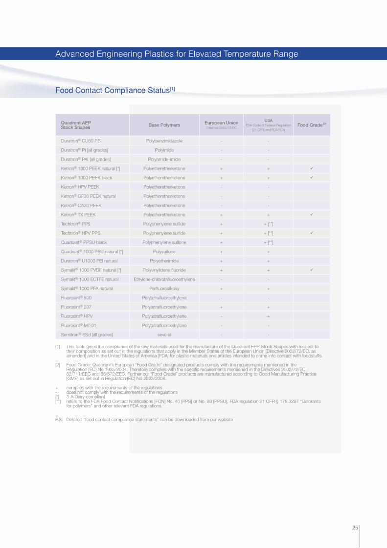
[1] This table gives the compliance of the raw materials used for the manufacture of the Quadrant EPP Stock Shapes with respect to their composition as set out in the regulations that apply in the Member States of the European Union [Directive 2002/72/EC, as amended] and in the United States of America [FDA] for plastic materials and articles intended to come into contact with foodstuffs.
[2] Food Grade: Quadrant’s European “Food Grade” designated products comply with the requirements mentioned in the Regulation [EC] No 1935/2004. Therefore complies with the specifi c requirements mentioned in the Directives 2002/72/EC, 82/711/EEC and 85/572/EEC. Further our “Food Grade” products are manufactured according to Good Manufacturing Practice [GMP] as set out in Regulation [EC] No 2023/2006.
+ complies with the requirements of the regulations- does not comply with the requirements of the regulations[*] 3-A Dairy compliant[**] refers to the FDA Food Contact Notifi cations [FCN] No. 40 [PPS] or No. 83 [PPSU], FDA regulation 21 CFR § 178.3297 “Colorants for polymers” and other relevant FDA regulations.
P.S. Detailed “food contact compliance statements” can be downloaded from our website.
Food Contact Compliance Status[1]
Advanced Engineering Plastics for Elevated Temperature Range

26
Duratron U1000 PEI is an amber translucent [non-optical quality] amorphous thermoplastic material, offering high strength and heat resistance. It performs continuously to 170 °C, making it ideal for high strength / high heat applications, and also for applications requiring consistent dielectric properties over a wide frequency and temperature range.
Main Characteristics
High maximum allowable service temperature in air [170 °C continuously] Very good hydrolysis resistance [suitable for repeated steam sterilisation] High strength and stiffness over a wide temperature range Inherent low fl ammability and low levels of smoke evolution during combustion Good dimensional stability Physiologically inert [food contact compliant composition] Very good resistance against high energy radiation [gamma- and X-rays] Very good electrical insulating and dielectric properties
Applications
Duratron U1000 PEI is extremely suitable for electrical / electronic insulators [including many semiconductor process components] and a variety of structural components requiring high strength and rigidity at elevated temperatures. Thanks to its good hydrolysis resistance, Duratron U1000 PEI is capable of withstanding repeated autoclaving cycles.
Duratron® LSG PEI [PEI; for Life Science Applications; natural] Within its portfolio of Life Science Grade Engineering Plastic Products - specifi cally developed for applications in the medical, pharmaceutical and biotechnology industries - Quadrant offers Duratron LSG PEI biocompatible engineering plastic stock shapes for machining with certifi ed USP Class VI and/or ISO 10993 compliance [see also page 73].
Tech Notes:
Cooling liquids of the soluble oil type should not be used when machining Duratron U1000 PEI since they are likely to induce environmental stress cracking. For this material, the most suitable coolants are pure water or compressed air [this also applies to Quadrant PPSU and Quadrant 1000 PSU].
Duratron® U1000 PEI Polyetherimide [PEI]
Advanced Engineering Plastics for Elevated Temperature Range

27
Symalit® 1000 PVDF Polyvinylidene Fluoride [PVDF]
This fl uoropolymer exhibits good mechanical properties combined with an excellent chemical resistance. It is a versatile engineering material especially suitable for the manufacture of components for the petro-chemical, chemical, metallurgical, food, paper, textile, pharmaceutical and nuclear industries.
Main Characteristics
High maximum allowable service temperature in air [150 °C continuously] Excellent chemical and hydrolysis resistance Moderate mechanical strength, stiffness and creep resistance High impact strength Very low water absorption Excellent UV-resistance [> 232 nm] and weatherability Physiologically inert [food contact compliant composition] Inherent low fl ammability Good electrical insulating properties
Grades
Symalit® 1000 PVDF [PVDF; natural white - available as “Food Grade“, details see page 25]Symalit 1000 PVDF is a highly crystalline unreinforced fl uoropolymer combining good mechanical, thermal and electrical properties with excellent chemical resistance. It also shows good resistance to high-energy radiation [considerably better than most other fl uoropolymers]. In addition, the composition of the raw material used for the production of Symalit 1000 PVDF stock shapes complies with the regulations of the European Union [Directive 2002/72/EC, as amended] and the United States of America [FDA] for plastic materials and articles intended to come into contact with foodstuffs.
Advanced Engineering Plastics for Elevated Temperature Range

28
Symalit 1000 ECTFE is made from a fl uoropolymer resin that is a copolymer of ethylene and chlorotrifl uoroethylene. It exhibits good mechanical properties combined with an excellent chemical resistance.
Main Characteristics
High maximum allowable service temperature in air [160 °C continuously] Excellent chemical and hydrolysis resistance Moderate mechanical strength, stiffness and creep resistance [lower than PVDF but much higher than PFA] Very high impact strength Excellent weathering resistance Very low water absorption Excellent release properties Easily weldable Good resistance to high energy radiation [gamma- and X-rays] Inherent low fl ammability and low levels of smoke evolution during combustion Good electrical insulating and dielectric properties
Grades
Symalit® 1000 ECTFE [ECTFE; natural (cream)]Symalit 1000 ECTFE is a highly crystalline unreinforced fl uoropolymer combining good mechanical, thermal and electrical properties with excellent chemical resistance. It also shows good resistance to high-energy radiation [considerably better than PTFE, PFA and PVDF].
Symalit® 1000 ECTFE Ethylene-Chlorotrifl uoroethylene [ECTFE]
Advanced Engineering Plastics for Elevated Temperature Range

29
Symalit 1000 PFA is made from a fl uoropolymer resin that is a copolymer of tetrafl uoroethylene and perfl uorovinylether. It exhibits good mechanical properties combined with excellent electrical properties and outstanding chemical and heat resistance.
Main Characteristics
Very high maximum allowable service temperature in air [250 °C continuously] Excellent chemical and hydrolysis resistance Moderate mechanical strength, stiffness and creep resistance [lower than ECTFE] Very high toughness and impact strength Excellent weatherability Very low water absorption Excellent release properties Physiologically inert [food contact compliant composition] Very low leach-out values for high purity applications Limited resistance to high energy radiation [similar to PTFE] Inherent low fl ammability Very good electrical insulating and dielectric properties
Grades
Symalit® 1000 PFA [PFA; natural white]Symalit 1000 PFA is a semi-crystalline unreinforced fl uoropolymer combining outstanding chemical and heat resistance with good mechanical properties. Another remarkable feature of this material is its outstanding electrical properties: a relative permittivity [dielectric constant] and dielectric dissipation factor coming very close to those of PTFE but an up to 4 times higher electric strength. Symalit 1000 PFA is used extensively in the chemical processing industries [CPI] and the semiconductor industry thanks to its virtually universal chemical resistance even at high temperatures [protective linings for pumps, valves, pipes scrubbing towers, tanks, vessels, reactors and heat exchangers].
Symalit® 1000 PFA Perfl uoroalkoxy [PFA]
Advanced Engineering Plastics for Elevated Temperature Range

30
The Fluorosint family of materials comprises several enhanced PTFE materials developed to fi ll the performance gaps where unfi lled and low-tech, fi lled PTFE based polymers underperform. Each Fluorosint grade was specifi cally developed to excel in demanding bearing and seal applications. While all of the Fluorosint grades possess the chemical resistance and compliance of PTFE, each grade offers some special benefi ts that give the designer clear performance advantages.
Main Characteristics
Very high maximum allowable service temperature in air [260 °C continuously] Moderate mechanical strength and stiffness Good dimensional stability Excellent chemical and hydrolysis resistance Low deformation under load [particularly Fluorosint MT-01] Low coeffi cient of friction and good wear resistance Outstanding UV- and weather resistance Physiologically inert [Fluorosint 207 and HPV have a food contact compliant composition] Inherent low fl ammability
Applications
High performance bearings, bushings and seals where higher loads and minimal wear are required.
Fluorosint® Polytetrafl uoroethylene [PTFE]
Advanced Engineering Plastics for Elevated Temperature Range

31
Grades
Fluorosint® 500 [PTFE + mica; ivory]Reinforced with a proprietary synthetic mica, this material exhibits, in addition to its inherent outstanding chemical and hydrolysis resistance, very good mechanical and tribological properties.Fluorosint 500 has nine times greater resistance to deformation under load than unfi lled PTFE. Its coeffi cient of linear thermal expansion approaches the expansion rate of aluminium and is 1/4 that of virgin PTFE, often eliminating fi t and clearance problems. It is considerably harder than virgin PTFE, has better wear characteristics and maintains low frictional properties.Fluorosint 500 enhanced PTFE offers an ideal combination of stability and wear resistance for sealing applications where tight dimensional control is required.
Fluorosint® 207 [PTFE + mica; white]This material has a food contact compliant composition which, in combination with the good mechanical performance, dimensional stability, sliding and wear properties and inherent outstanding chemical and hydrolysis resistance of Fluorosint, opens numerous application possibilities in food, pharmaceutical and chemical processing industries.Fluorosint 207 lasts far longer than unfi lled PTFE in wear applications and has a very low coeffi cient of friction. It is a preferred material for lower pressure seats and seals where virgin PTFE fails and food contact compliance may be required.
Fluorosint® HPV [PTFE + additives; tan]FDA compliant Fluorosint HPV is a high performance Fluorosint bearing grade, optimized for high pressure-velocity capabilities and very low wear. Fluorosint HPV was developed for bearing applications where other, low-tech PTFE formulations exhibit premature wear or simply cannot perform. FDA compliance gives food and pharmaceutical equipment manufacturers new design options and all benefi t from its excellent load bearing and wear characteristics.
Fluorosint® MT-01 [PTFE + additives; dark grey]Fluorosint MT-01 is an extreme service grade developed specifi cally for applications where the benefi ts of PTFE-based materials also require strength, stiffness and stability. Fluorosint MT-01 delivers high mechanical performance at elevated temperature and as a result is often specifi ed in seat, seal and wear applications where extreme conditions are present.
Fluorosint® Polytetrafl uoroethylene [PTFE]
Tech Notes:
The mechanical performance of the Symalit®
and the Fluorosint® grades is not as good as the one of other advanced engineering plastics profi led in this product and application guide such as Ketron® PEEK and Duratron® PAI.
Advanced Engineering Plastics for Elevated Temperature Range

Fig. 8: Surface Resistivity [Ohm/Sq.] and Conductivity Spectrum
105 1010 1012
static dissipativeconductive insulative
high resistivity [HR]
[Ohm/sq.]
32
The Semitron ESd family of static dissipative plastics is designed for applications where electrical discharge in operation is a problem. They provide a controlled bleed-off of static charges.
Main Characteristics
Permanently static dissipative Dissipate static charges [5kV] in less than 2 seconds No metal or graphite powder used Depending on the base polymer, thermal performance from 90 to 260 °C [continuous use]
Applications
There are four Semitron ESd grades servicing static dissipative needs over a broad range of temperatures and mechanical loading conditions.The Semitron ESd materials are commonly used in manufacturing and handling equipment of sensitive electronic components such as integrated circuits, hard disk drives and circuit boards. They are also an excellent choice for material handling applications and components in high speed electronic printing and reproducing equipment.
Semitron® ESd
Advanced Engineering Plastics for Elevated Temperature Range

Semitron® ESd grades Surface resistivity [Ohm/sq.]acc. to ANSI/ESD STM 11.11
Max. allowable service temperature in air [°C] for short
periods | continuously [*]
Semitron ESd 225 109 - 1011 140 | 90
Semitron ESd 410C 104 - 106 200 | 170
Semitron ESd 500HR 1010 - 1012 280 | 260
Semitron ESd 520HR 1010 - 1012 270 | 250
33
Grades
Semitron® ESd 225 [static dissipative POM; beige]Semitron ESd 225 is an acetal based static dissipative material ideal for material handling operations. It is also an excellent choice for fi xturing used in the manufacturing of hard disk drives or for handling in-process silicon wafers.
Semitron® ESd 410C [static dissipative PEI; black]Having an excellent mechanical performance up to 210 °C, Semitron ESd 410C provides ESd solutions at higher temperatures.Additionally, Semitron ESd 410C exhibits excellent dimensional stability [low coeffi cient of linear thermal expansion and small water absorption], ideal for handling equipment in the electrical/electronic or semiconductor industries.
Semitron® ESd 500HR [static dissipative PTFE; white]Reinforced with a proprietary synthetic mica, Semitron ESd 500HR offers an excellent combination of low frictional properties, good dimensional stability and electrostatic dissipation. Whenever virgin PTFE causes electrical discharge problems, Semitron ESd 500HR will provide a controlled bleed-off of static charges while maintaining typical PTFE-properties such as broad chemical resistance and low coeffi cient of friction.
Semitron® ESd 520HR [static dissipative PAI; khaki grey]Semitron ESd 520HR has an industry fi rst combination of electrostatic dissipation [ESd], high strength and heat resistance. This new ESd material is ideal for making nests, sockets and contactors for test equipment and other device handling components in the semiconductor industry.The key feature of Semitron 520HR is its unique ability to resist dielectric breakdown at high voltages [>100 V]. Whereas e.g. typical carbon fi bre enhanced products become irreversibly more conductive when exposed to even moderate voltages, Semitron ESd 520HR maintains its electrical performance throughout the voltage range 100 to 1000 V, while offering the mechanical performance needed to excel in demanding applications.
Tech Notes:
The Semitron ESd products are inherently dissipative and do not rely on atmospheric phenomena [e.g. humidity] to activate, nor are surface treatments used to achieve dissipation.
Semitron® ESd
[*] for more details, see the property list on page 77.
Advanced Engineering Plastics for Elevated Temperature Range
Coe
ffi ci
ent o
f lin
ear
ther
mal
exp
ansi
on (C
LTE
) [10
-6 m
/(m.K
)]
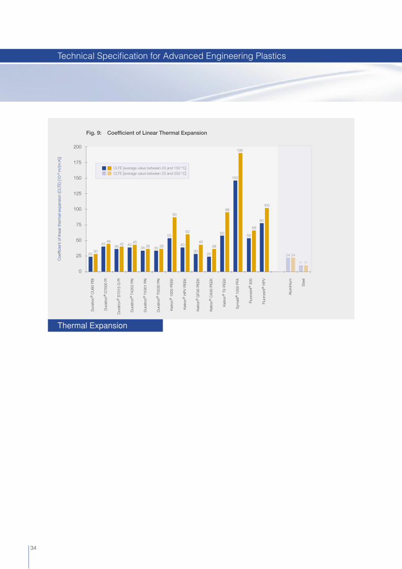
Fig. 9: Coeffi cient of Linear Thermal Expansion
Dur
atro
n® C
U60
PB
I
Dur
atro
n® D
7000
PI
Dur
atro
n® D
7015
G P
I
Dur
atro
n® T
4203
PA
I
Dur
atro
n® T
4301
PA
I
Dur
atro
n® T
5530
PA
I
Ket
ron®
100
0 P
EE
K
Ket
ron®
HP
V P
EE
K
Ket
ron®
GF3
0 P
EE
K
Ket
ron®
CA
30 P
EE
K
Ket
ron®
TX
PE
EK
Sym
alit®
100
0 P
FA
Fluo
rosi
nt®
500
Fluo
rosi
nt®
HP
V
Alu
min
ium
Ste
el
200
175
150
125
100
75
50
25
0
1111
24 24
80
105
68
56
195
150
98
60
38
25
45
30
90
5562
40383530
25
4642 42
3845
40 3835
CLTE [average value between 23 and 150 °C]CLTE [average value between 23 and 250 °C]
1111
24 24
34
Thermal Expansion
Technical Specifi cation for Advanced Engineering Plastics

Line
ar e
xpan
sion
at s
atur
atio
n in
wat
er o
f 23
°C [%
]
Fig. 10: Dimensional Stability [coeffi cient of linear thermal expansion and expansion due to water absorption]
Dur
atro
n® C
U60
PB
I
Dur
atro
n® D
7000
PI
Dur
atro
n® T
4203
PA
I
Dur
atro
n® T
4301
PA
I
Ket
ron®
100
0 P
EE
K
Ket
ron®
HP
V P
EE
K
Ket
ron®
GF3
0 P
EE
K
Ket
ron®
CA
30 P
EE
K
Tech
tron
® H
PV
PP
S
Qua
dran
t® P
PS
U
Dur
atro
n® U
1000
PE
I
Sym
alit®
100
0 P
VD
F
Fluo
rosi
nt®
500
Fluo
rosi
nt®
HP
V
Ert
alon
® 6
SA
Ert
alyt
e®
3
2
1
0
210
180
150
120
90
60
30
0
Coe
ffi ci
ent o
f lin
ear
ther
mal
exp
ansi
on [1
0-6 m
/(m.K
)][a
vera
ge v
alue
bet
wee
n 23
and
100
°C
]
Coe
ffi ci
ent o
f lin
ear
ther
mal
exp
ansi
on (C
LTE
) [10
-6 m
/(m.K
)]
Fig. 11: Coeffi cient of Linear Thermal Expansion of Fluorosint
Fluorosint® 207
average value between 23 and 100 °Caverage value between 23 and 150 °Caverage value between 150 and 250 °C
300
250
200
150
100
50
0
Fluorosint® 500 Fluorosint® HPV Fluorosint® MT-01 PTFE Aluminium
270
200200
24 2524
100
135
6560
8075
9085
155
5550
85
35
Dimensional Stability
Dimensional Stability
Technical Specifi cation for Advanced Engineering Plastics

Coe
ffi ci
ent o
f lin
ear
ther
mal
exp
ansi
on
(CLT
E) [
10-6
m/(m
.K)]
Fig. 12: Coeffi cient of Linear Thermal Expansion versus Temperature [measured by TMA acc. to ASTM E 831]
Temperature [°C]
350
300
250
200
150
100
50
0-50 200150100500 250
Mod
ulus
of e
last
icity
[MP
a]
Fig. 13: Stiffness versus Temperature [derived from DMA-curves]
7000
6000
5000
4000
3000
2000
1000
0
Temperature [°C]
-50 200150100500 250 350300
Duratron® CU60 PBIDuratron® D7000 PIDuratron® D7015G PIDuratron® T4203 PAIDuratron® T4301 PAIDuratron® T5530 PAIErtacetal® C
Duratron® CU60 PBIDuratron® D7000 PIDuratron® T4203 PAIKetron® 1000 PEEKFluorosint® 207
36
Modulus of Elasticity
Dimensional Stability
Technical Specifi cation for Advanced Engineering Plastics

Mod
ulus
of e
last
icity
[MP
a]
Fig. 14: Stiffness versus Temperature [derived from DMA-curves]
Mod
ulus
of e
last
icity
[MP
a]
Fig. 15: Stiffness versus Temperature [derived from DMA-curves]
10000
9000
8000
7000
6000
5000
4000
3000
2000
1000
0
-50 200150100500 300250
4500
4000
3500
3000
2500
2000
1500
1000
500
0
-50 200150100500 300250
Ketron® 1000 PEEKKetron® HPV PEEKKetron® GF30 PEEKKetron® CA30 PEEKKetron® TX PEEKTechtron® HPV PPSErtacetal® C
Temperature [°C]
Temperature [°C]
Quadrant® PPSUQuadrant® 1000 PSUDuratron® U1000 PEISymalit® 1000 PVDFSymalit® 1000 ECTFESymalit® 1000 PFAFluorosint® 500Fluorosint® 207Fluorosint® HPVFluorosint® MT-01Ertacetal® C
37
Modulus of Elasticity
Modulus of Elasticity
Technical Specifi cation for Advanced Engineering Plastics

Com
pres
sive
str
ess
at 2
% n
omin
al s
trai
n [M
Pa]
Fig. 16: Compression Test at 23 °C* [ISO 604] [test run on cylinders dia. 8 x 16 mm long]
140
120
100
80
60
40
20
0
Fig. 17: Deformation of Fluorosint under Compressive Load
Creep after 24 hours under a compressive stress of 13.8 MPa [2000 psi] at 50 °C - [%]
43210 5 76 8 9 10
9
8,4
3,5
3,2
0,7
1,1
Dur
atro
n® C
U60
PB
I
Dur
atro
n® D
7000
PI
Dur
atro
n® D
7015
G P
I
Dur
atro
n® T
4203
PA
I
Dur
atro
n® T
4301
PA
I
Dur
atro
n® T
5530
PA
I
Ket
ron®
100
0 P
EE
K
Ket
ron®
HP
V P
EE
K
Ket
ron®
GF3
0 P
EE
K
Ket
ron®
CA
30 P
EE
K
Ket
ron®
TX
PE
EK
Tech
tron
® H
PV
PP
S
Qua
dran
t® P
PS
U
Qua
dran
t® 1
000
PS
U
Dur
atro
n® U
1000
PE
I
Sym
alit®
100
0 P
VD
F
Sym
alit®
100
0 E
CTF
E
Sym
alit®
100
0 P
FA
Fluo
rosi
nt®
500
Fluo
rosi
nt®
HP
V
118
69
81
14,510,5
6772
104
7580
103
125
10
26
36
61
49
41
6561
*: measured on dry test specimens
38
Fluorosint® MT-01
Fluorosint® 500
Fluorosint® HPV
Fluorosint® 207
PTFE-GF 25
PTFE
Deformation under Load
Deformation under Load
Technical Specifi cation for Advanced Engineering Plastics

Fig. 18: Min./Max. Service Temperature in Air and Coeffi cient of Linear Thermal Expansion
550
500
450
400
350
300
250
200
150
100
50
0
-50
-100
-150
-200
250
225
200
175
150
125
100
75
50
25
0
Coe
ffi ci
ent o
f lin
ear
ther
mal
exp
ansi
on (
CLT
E)
[10-6
m/(
m.K
)][a
vera
ge
valu
e b
etw
een
23 a
nd 1
50 °
C]
Tem
per
atur
e [°
C]
500
300
270
250
250
-50
450
240
450
240 27
025
0
310
250
310
250
310
250
310
220
260
180
210
17020
0
150160
-20
-50
-50
-200
-50
Max. allowable temperature for short periods [a few hours]
Max. continuously allowable temperature [20.000 h]
Min. service temperature
coeffi cient of linear thermal expansion [CLTE]
26028
0
26028
0
-50
-50
-20
-20
-20
-50
-20
-20
-50
250
280
-20
39
Dur
atro
n® C
U60
PB
I
Dur
atro
n® D
7000
PI
Dur
atro
n® D
7015
G P
I
Dur
atro
n® T
4203
PA
I
Dur
atro
n® T
4301
PA
I
Ket
ron®
100
0 P
EE
K
Ket
ron®
HP
V P
EE
K
Ket
ron®
GF3
0 P
EE
K
Ket
ron®
CA
30 P
EE
K
Tech
tron
® H
PV
PP
S
Qua
dran
t® P
PS
U
Dur
atro
n® U
1000
PE
I
Sym
alit®
100
0 P
VD
F
Sym
alit®
100
0 P
FA
Fluo
rosi
nt®
500
Fluo
rosi
nt®
HP
V
Allu
min
ium
Ste
el
Min./Max. Service Temperature
Technical Specifi cation for Advanced Engineering Plastics

Tem
pera
ture
of d
efl e
ctio
n un
der
load
acc
. to
ISO
75
Met
hod
A :
1.8
MP
a [°
C]
Fig. 19: Temperature of Defl ection under Load versus max. allowable Service Temperature in Air
Max. allowable service temperature in air [continuously for min. 20.000 h] - [°C]
450
400
350
300
250
200
150
100
50
0
300250200500 350150100
Ertalon® 6 SA
Ertalyte®
Symalit® 1000 PVDF
Quadrant® 1000 PSU
Quadrant® PPSU
Symalit® 1000 ECTFE Symalit® 1000 PFA
Duratron® U1000 PEI
Ketron® TX PEEK
Techtron® HPV PPSFluorosint® HPV
Fluorosint® 207
Fluorosint® 500
Ketron® 1000 PEEK
Ketron® HPV PEEK
Ketron® GF30 PEEK
Ketron® CA30 PEEK
Duratron® D7000 PIDuratron® D7015G PI
Duratron® CU60 PBI
Duratron® T4203/4301/5530 PAI
Str
ess
[MP
a]
Fig. 20: Stress Relaxation at 23 °C | Isometric Stress-Time Curves for a Deformation of 1 % [derived from creep tests]
Loading time [hours]
50
40
30
20
10
01 10 100 1000 10000
Duratron® CU60 PBIDuratron® D7000 PIDuratron® T4203 PAIKetron® 1000 PEEKTechtron® HPV PPSDuratron® U1000 PEI
40
Temperature of Defl ection
Stress Relaxation
Technical Specifi cation for Advanced Engineering Plastics

Str
ess
[MP
a]
Fig. 21: Stress Relaxation at 80 °C | Isometric Stress-Time Curves for a Deformation of 1 % [derived from creep tests]
40
30
20
10
01 10 100 1000 10000
Fig. 22: Stress Relaxation at 150 °C | Isometric Stress-Time Curves for a Deformation of 1 % [derived from creep tests]
40
30
20
10
01 10 100 1000 10000
Str
ess
[MP
a]
Loading time [hours]
Duratron® CU60 PBIDuratron® D7000 PIDuratron® T4203 PAIKetron® 1000 PEEKTechtron® HPV PPSDuratron® U1000 PEI
Loading time [hours]
Duratron® CU60 PBIDuratron® D7000 PIDuratron® T4203 PAIKetron® 1000 PEEKTechtron® HPV PPSDuratron® U1000 PEI
41
Stress Relaxation
Stress Relaxation
Technical Specifi cation for Advanced Engineering Plastics

Fig. 23: Wear Resistance [measured on a „plastics pin on rotating steel disk“ - tribo system]
Fig. 24: Wear Resistance [measured on a „plastics pin on rotating steel disk“ - tribo system]
3
Wea
r rat
e [µ
m/k
m]
80
70
60
50
40
30
20
10
0
12
70
1
5
28
7
2
9
53
14
2
Dur
atro
n® C
U60
PB
I
Dur
atro
n® D
7000
PI
Dur
atro
n® T
4203
PA
I
Dur
atro
n® T
4301
PA
I
Ket
ron®
100
0 P
EE
K
Ket
ron®
HP
V P
EE
K
Ket
ron®
GF3
0 P
EE
K
Ket
ron®
CA
30 P
EE
K
Ket
ron®
TX
PE
EK
Tech
tron
® P
PS
Tech
tron
® H
PV
PP
S
Ert
alon
® 6
6 S
A
Ert
alyt
e®
2500
Wea
r rat
e [µ
m/k
m]
80
70
60
50
40
30
20
10
0
12
52,5 3
Qua
dran
t® P
PS
U
Qua
dran
t® 1
000
PS
U
Dur
atro
n® U
1000
PE
I
Sym
alit®
100
0 P
VD
F
Sym
alit®
100
0 E
CTF
E
Sym
alit®
100
0 P
FA
Fluo
rosi
nt®
500
Fluo
rosi
nt®
207
Fluo
rosi
nt®
HP
V
Fluo
rosi
nt®
MT-
01
Ert
alon
® 6
6 S
A
Ert
alyt
e®
PTF
E
14
1450110045513256400
6
1600
Test conditions:
pressure: 3 MPasliding velocity: 0.33 m/ssurface roughness of the C35 steel mating surface: Ra = 0.70 - 0.90 µmtotal distance run: 28 kmnormal environment [air, 23 °C / 50 % RH]unlubricated operation
Test conditions:
pressure: 3 MPasliding velocity: 0.33 m/ssurface roughness of the C35 steel mating surface: Ra = 0.70 - 0.90 µmtotal distance run: 28 kmnormal environment [air, 23 °C / 50 % RH]unlubricated operation
42
Wear Resistance
Wear Resistance
Technical Specifi cation for Advanced Engineering Plastics

Fig. 25: Dynamic Coeffi cient of Friction [measured on a „plastics pin on rotating steel disk“ - tribo system]
Fig. 26: Dynamic Coeffi cient of Friction [measured on a „plastics pin on rotating steel disk“ - tribo system]
Dur
atro
n® C
U60
PB
I
Dur
atro
n® D
7000
PI
Dur
atro
n® T
4203
PA
I
Dur
atro
n® T
4301
PA
I
Ket
ron®
100
0 P
EE
K
Ket
ron®
HP
V P
EE
K
Ket
ron®
GF3
0 P
EE
K
Ket
ron®
CA
30 P
EE
K
Ket
ron®
TX
PE
EK
Tech
tron
® P
PS
Tech
tron
® H
PV
PP
S
Ert
alon
® 6
6 S
A
Ert
alyt
e®
Qua
dran
t® P
PS
U
Qua
dran
t® 1
000
PS
U
Dur
atro
n® U
1000
PE
I
Sym
alit®
100
0 P
VD
F
Sym
alit®
100
0 E
CTF
E
Sym
alit®
100
0 P
FA
Fluo
rosi
nt®
500
Fluo
rosi
nt®
207
Fluo
rosi
nt®
HP
V
Fluo
rosi
nt®
MT-
01
Ert
alon
® 6
6 S
A
Ert
alyt
e®
PTF
E
0,40
0,60
0,15
0,25Dyn
amic
coe
ffi ci
ent o
f fric
tion
[-]
1,00
0,90
0,80
0,70
0,60
0,50
0,40
0,30
0,20
0,10
0,00
0,20
0,350,40
0,60
0,30
0,45
0,25
0,35
0,20
0,30
0,15
0,250,30
0,50
0,25
0,40
0,35
0,60
0,30
0,50
0,30
0,50
Test conditions:
pressure: 3 MPasliding velocity: 0.33 m/ssurface roughness of the C35 steel mating surface: Ra = 0.70 - 0.90 µmtotal distance run: 28 kmnormal environment [air, 23 °C / 50 % RH]unlubricated operation
0,15
0,25
0,10
0,20
Dyn
amic
coe
ffi ci
ent o
f fric
tion
[-]
1,00
0,90
0,80
0,70
0,60
0,50
0,40
0,30
0,20
0,10
0,00
0,20
0,30
0,20
0,30
0,15
0,25
0,25
0,35
0,50
0,40
0,50
Test conditions:
pressure: 3 MPasliding velocity: 0.33 m/ssurface roughness of the C35 steel mating surface: Ra = 0.70 - 0.90 µmtotal distance run: 28 kmnormal environment [air, 23 °C / 50 % RH]unlubricated operation
0,40
0,60
0,15
0,250,35
0,45
0,35
0,45
0,60
0,30
0,40
43
Dynamic Coeffi cient of Friction
Dynamic Coeffi cient of Friction
Technical Specifi cation for Advanced Engineering Plastics

Fig. 27: Limiting PV-Values for Cylindrical Sleeve Bearings [*]
HIGHER IS BETTERsliding velocity = 0.1 m/ssliding velocity = 1 m/s
Lim
iting
PV-
valu
e [M
Pa.m
/s]
2.0
1.8
1.6
1.4
1.2
1.0
0.8
0.6
0.4
0.2
0
Dur
atro
n® C
U60
PB
I
Dur
atro
n® D
7000
PI
Dur
atro
n® D
7015
G P
I
Dur
atro
n® T
4203
PA
I
Dur
atro
n® T
4301
PA
I
Ket
ron®
100
0 P
EE
K
Ket
ron®
HP
V P
EE
K
Ket
ron®
CA
30 P
EE
K
Ket
ron®
TX
PE
EK
Tech
tron
® H
PV
PP
S
Sym
alit®
100
0 P
VD
F
Fluo
rosi
nt®
500
Fluo
rosi
nt®
207
Fluo
rosi
nt®
HP
V
Fluo
rosi
nt®
MT-
01
[*] The limiting PV-values given in the graph refer to properly designed plastics-metals combinations with excellent heat dissipation characteristics that operate continuously and without lubrication in a normal air environment of about 23 °C [e.g. a steel shaft rotating in a thin walled plastics bushing with a length to I.D. ratio of max. 1]. Obviously, higher PV-values can be allowed in case of intermittent or lubricated operation.
44
PV-Values
Technical Specifi cation for Advanced Engineering Plastics

45
Technical Specifi cation for Advanced Engineering Plastics

46
Within the polyamides, commonly referred to as “nylons”, we distinguish different types. The most important ones are: PA 6, PA 66, PA 11 and PA 12. The differences in physical properties which exist between these types are mainly determined by the composition and the structure of their molecular chains.
Main Characteristics
High mechanical strength, stiffness, hardness and toughness Good fatigue resistance High mechanical damping ability Good sliding properties Excellent wear resistance Good electrical insulating properties Good resistance to high energy radiation [gamma- and X-rays] Good machinability
Applications
Sleeve and slide bearings, wear pads, support and guide wheels, conveyor rollers, tension rollers, sleeves for wheels and rollers, pulleys and pulley-linings, cams, buffer blocks, hammer heads, scrapers, gear wheels, sprockets, seal-rings, feed screws, star wheels, cutting and chopping boards, insulators
Extruded Nylon Grades
Ertalon® 6 SA [PA 6; natural (white)* / black - available as “Food Grade“, details see page 51]This material offers an optimal combination of mechanical strength, stiffness, toughness, mechanical damping properties and wear resistance. These properties, together with good electrical insulating properties and a good chemical resistance make Ertalon 6 SA a “general purpose” grade for mechanical construction and maintenance.
Ertalon® 66 SA [PA 66; natural (cream)* / black - available as “Food Grade“, details see page 51]Material with a higher mechanical strength, stiffness, heat and wear resistance than Ertalon 6 SA. It also has a better creep resistance but its impact strength and mechanical damping ability is reduced. Well suited for machining on automatic lathes. Please note that the Ertalon 66 SA natural rods over dia. 150 mm are made from a modifi ed polyamide 66 resin [see the property values given on page 78 under Ertalon 66 SA-C].
Ertalon® 4.6 [PA 4.6; reddish brown]Compared with conventional nylons, Ertalon 4.6 features a better retention of stiffness and creep resistance over a wide range of temperatures as well as superior heat ageing resistance. Therefore, applications for Ertalon 4.6 are situated in the “higher temperature area” [80 – 150 °C] where stiffness, creep resistance, heat ageing resistance, fatigue strength and wear resistance of PA 6, PA 66, POM and PET fall short.
Ertalon® 66-GF30 [PA 66-GF30; black]Compared with virgin PA 66, this 30 % glass fi bre reinforced and heat stabilised nylon grade offers increased strength, stiffness, creep resistance and dimensional stability whilst retaining an excellent wear resistance. It also allows higher max. service temperatures.
[*] See Food Contact Compliance Status on Page 51.
Ertalon® | Nylatron® Polyamide [PA]
General Engineering Plastics for Medium Temperature Range

47
Nylatron® GS [PA 66 + MoS2; grey-black]The addition of MoS2 renders this material somewhat stiffer, harder and dimensionally more stable than Ertalon 66 SA, but results in some loss of impact strength. The nucleating effect of the molybdenum disulphide results in an improved crystalline structure enhancing bearing and wear properties.
Cast Nylon Grades
Ertalon® 6 PLA [PA 6; natural (ivory)* / black / blue]Unmodifi ed cast nylon 6 grade exhibiting characteristics which come very close to those of Ertalon 66 SA. It combines high strength, stiffness and hardness with good creep and wear resistance, heat ageing properties and machinability.
Ertalon® 6 XAU+ [PA 6; black]Ertalon 6 XAU+ is a heat stabilized cast nylon grade with a very dense and highly crystalline structure. Compared with conventional extruded or cast nylons, Ertalon 6 XAU+ offers superior heat ageing performance in air [much better resistance to thermaloxidative degradation], allowing 15 - 30 °C higher continuously allowable service temperatures. Ertalon 6 XAU+ is particularly recommended for bearings and other mechanical parts subject to wear which are operating in air for long periods of time at temperatures over 60 °C.
Ertalon® LFX [PA 6 + oil; green]This internally lubricated cast nylon 6 is self-lubricating in the real meaning of the word. Ertalon LFX, especially developed for unlubricated, highly loaded and slow moving parts applications, yields a considerable enlargement of the application opportunities compared to standard cast nylons. It offers a reduced coeffi cient of friction [up to 50 % lower], considerably increasing the pressure-velocity capabilities, and a vastly improved wearresistance [up to 10 times better].
Nylatron® MC 901 [PA 6; blue]This modifi ed cast nylon 6 grade with its distinctive blue colour exhibits higher toughness, fl exibility and fatigue resistance than Ertalon 6 PLA. It has proved to be an excellent material for gear wheels, racks and pinions.
Nylatron® GSM [PA 6 + MoS2; grey-black]Nylatron GSM contains fi nely divided particles of molybdenum disulphide to enhance its bearing and wear behaviour without impairing the impact and fatigue resistance inherent to unmodifi ed cast nylon grades. It is a very commonly used grade for gears, bearings, sprockets and sheaves.
Nylatron® NSM [PA 6 + solid lubricants; grey]Nylatron NSM is a proprietary cast nylon 6 formulation containing solid lubricant additives which grant this materials self-lubricity, excellent frictional behaviour, superior wear resistance and outstanding pressure-velocity capabilities [up to 5 times higher than conventional cast nylons]. Being particularly suited for higher velocity, unlubricated moving parts applications, it is the perfect complement to the oil-fi lled grade Ertalon LFX.
Nylatron® LFG [PA 6 + oil; natural (ivory) / blue]Nylatron LFG [Lubricated Food Grade] is self-lubricating in the real meaning of the word, and has a FDA food contact compliant composition. The Nylatron LFG has been specially developed for non-lubricated, highly loaded and slowly moving parts in food contact applications. Compared to standard cast nylons, it offers lower maintenance costs and longer service life.
[*] See Food Contact Compliance Status on Page 51.
Ertalon® | Nylatron® Polyamide [PA]
General Engineering Plastics for Medium Temperature Range

48
Nylatron® 703 XL [PA 6 + internal lubricants; purple]This high performance cast nylon 6 bearing grade provides an even better wear resistance than Nylatron NSM, combined with superior pressure-velocity capabilities and an industry fi rst: a near zero level of “stick-slip”. The elimination of stick-slip, mostly associated with chatter or squeaking, provides an extraordinary amount of motion control for high-precision applications.
Nylatron® MD [PA 6; dark blue - available as “Food Grade“, details see page 51] This nylon 6 grade contains a metal detectable additive and has been specifi cally tailored for use in the food processing and packaging industries where it can easily be traced by the conventional metal detection systems installed to detect contamination of the foodstuffs [results may vary depending on the sensitivity of the metal detection system used]. Nylatron MD is a material with higher wear and fatigue resistance and shows lower moisture absorption than standard PA 6. It is applied in temperature environments of up to 80 °C and also features a food contact compliant composition.
Tech Notes:
Nylons can absorb up to 9 % by weight of water under high humidity or submerged in water. This results in dimensional changes and a corresponding reduction of physical properties. Proper design techniques can frequently compensate for this factor.
Ertalon® | Nylatron® Polyamide [PA]
General Engineering Plastics for Medium Temperature Range

49
Tech Notes:
When it comes to outdoor applications Ertacetal is not recommended because of its poor UV-resistance.
Quadrant Engineering Plastic Products offers both homopolymer and copolymer grades of Ertacetal including an enhanced bearing grade material.
Main Characteristics
High mechanical strength, stiffness and hardness Excellent resilience Good creep resistance High impact strength, even at low temperatures Very good dimensional stability [low water absorption] Good sliding properties and wear resistance Excellent machinability Good electrical insulating and dielectric properties Physiologically inert [several grades have a food contact compliant composition] Not self-extinguishing
Applications
Gear wheels with small modulus, cams, heavily loaded bearings and rollers, bearings and gears with small clearances, valve seats, snapfi t assemblies, dimensionally stable precision parts, electrically insulating components.
Grades
Ertacetal® C [POM-C; natural (white)* / black / colours* - available as “Food Grade“, details see page 51]Ertacetal C is Quadrant’s copolymer acetal grade. Next to the standard natural and black grades, there is also a series of special colours available all showing an FDA food contact compliant composition. The acetal copolymer is more resistant against hydrolysis, strong alkalis and thermaloxidative degradation than the acetal homopolymer.
Ertacetal® H [POM-H; natural (white) / black]Ertacetal H is Quadrant’s homopolymer acetal grade. It offers a higher mechanical strength, stiffness, hardness and creep resistance as well as a lower thermal expansion rate and often also a better wear resistance than the acetal copolymer.
Ertacetal® H-TF [POM-H + PTFE; deep brown]Ertacetal H-TF is a DELRIN® AF Blend, a combination of PTFE fi bres evenly dispersed in a DELRIN acetal resin. Much of the strength that is inherent in Ertacetal H is retained. Some properties change due to the addition of PTFE fi bre which is softer, less stiff and slipperier than virgin acetal resin. Compared with Ertacetal C and H, this material offers superior sliding properties. Bearings made of Ertacetal H-TF show low friction, long wear and are essentially free of stick-slip behaviour.
[*] See Food Contact Compliance Status on Page 51.
Ertacetal® | Acetron® Polyacetal [POM]
General Engineering Plastics for Medium Temperature Range

50
Acetron® MD [POM-C; blue - available as “Food Grade“, details see page 51] This copolymer acetal grade, containing a metal detectable additive, has been specifi cally tailored for use in the food processing and packaging industries where it can easily be traced by the conventional metal detection systems installed to detect contamination of the foodstuffs [results may vary depending on the sensitivity of the metal detection system used]. Acetron MD presents good mechanical strength, stiffness and impact strength, and it also features a food contact compliant composition.
Acetron® LSG [POM-C; for Life Science Applications; natural / black] Within its portfolio of Life Science Grade Engineering Plastic Products - specifi cally developed for applications in the medical, pharmaceutical and biotechnology industries - Quadrant offers Acetron LSG biocompatible engineering plastic POM-C stock shapes for machining with certifi ed ISO 10993 compliance [see also page 73].
Ertacetal® | Acetron® Polyacetal [POM]
General Engineering Plastics for Medium Temperature Range

51
Quadrant GEPStock Shapes Base Polymers European Union
Directive 2002/72/EC
USAFDA Code of Federal Regulation
[21 CFR]Food Grade[2]
Ertalon® 6 SA natural Polyamide 6 + + ü
Ertalon® 66 SA natural Polyamide 66 + + ü
Ertalon® 6 SA & 66 SA black Polyamide 6 & 66 - -
Ertalon® 4.6 Polyamide 4.6 - -
Ertalon® 66-GF30 Polyamide 66 - -
Nylatron® GS Polyamide 66 + -
Ertalon® 6 PLA natural & blue Polyamide 6 + +
Nylatron® LFG natural/blue Polyamide 6 - +
Nylatron® MD dark blue Polyamide 6 + + ü
other cast nylon grades Polyamide 6 - -
Ertacetal® C natural [*] Polyacetal Copolymer + + ü
Ertacetal® C black Polyacetal Copolymer - -
Ertacetal® C Blue 50 & Black 90 Polyacetal Copolymer + + ü
Ertacetal® C other colours Polyacetal Copolymer - +
Acetron® MD blue Polyacetal Copolymer + + ü
Ertacetal® H natural Polyacetal Homopolymer - -
Ertacetal® H black & H-TF Polyacetal Homopolymer - -
Ertalyte® natural [*] Polyethylene terephthalate + + ü
Ertalyte® black Polyethylene terephthalate + - ü
Ertalyte® TX Polyethylene terephthalate + + ü
Quadrant® 1000 PC natural Polycarbonate + +
[1] This table gives the compliance of the raw materials used for the manufacture of the Quadrant EPP Stock Shapes with respect to their composition as set out in the regulations that apply in the Member States of the European Union [Directive 2002/72/EC, as amended] and in the United States of America [FDA] for plastic materials and articles intended to come into contact with foodstuffs.
[2] Food Grade: Quadrant’s European “Food Grade” designated products comply with the requirements mentioned in the Regulation [EC] No 1935/2004. Therefore complies with the specifi c requirements mentioned in the Directives 2002/72/EC, 82/711/EEC and 85/572/EEC. Further our “Food Grade” products are manufactured according to Good Manufacturing Practice [GMP] as set out in Regulation [EC] No 2023/2006.
+ complies with the requirements of the regulations- does not comply with the requirements of the regulations[*] 3-A Dairy compliant
P.S. Detailed “food contact compliance statements” can be downloaded from our website.
Food Contact Compliance Status[1]
General Engineering Plastics for Medium Temperature Range

52
Quadrant Engineering Plastic Products’ stock shapes made of crystalline thermoplastic polyester are marketed under the trade names Ertalyte [virgin grade] and Ertalyte TX [bearing grade].
Main Characteristics
High mechanical strength, stiffness and hardness Very good creep resistance Low and constant coeffi cient of friction Excellent wear resistance [comparable with or even better than nylon grades] Moderate impact strength Very good dimensional stability [better than polyacetal] Excellent stain resistance Better resistance to acids than nylon or polyacetal Good electrical insulating properties Physiologically inert [food contact compliant composition] Good resistance to high energy radiation [gamma and X-rays]
Applications
Heavily loaded bearings [bushings, thrust washers, guides, etc.], dimensionally stable parts for mechanisms of precision [bushings, slideways, gears, rollers, pump components, etc.], insulating components for electrical engineering.
Grades
Ertalyte® [PET; natural (white)* / black - available as “Food Grade“, details see page 51]The specifi c properties of this virgin crystalline PET make it especially suitable for the manufacture of mechanical precision parts which have to sustain high loads and/or are subject to wear.
Ertalyte® TX [PET + solid lubricant; pale grey - available as “Food Grade“, details see page 51]Ertalyte TX is a polyethylene terephthalate compound incorporating a uniformly dispersed solid lubricant. Its specifi c formulation makes it a premium internally lubricated bearing grade. Ertalyte TX not only has got an outstanding wear resistance, but offers in comparison with Ertalyte an even lower coeffi cient of friction as well as higher pressurevelocity capabilities.
[*] See Food Contact Compliance Status on Page 51.
Ertalyte® Polyethylene Terephthalate [PET]
Tech Notes:
Since Ertalyte tends to be rather notch and impact sensitive, all “internal” corners should be radiused [R > 1 mm] and to avoid chipping the edges during turning, boring or milling, chamfered edges are advantageous, providing a smoother transition between the cutting tool and the plastics work.
General Engineering Plastics for Medium Temperature Range

53
Quadrant Engineering Plastic Products is marketing non-UV-stabilized polycarbonate stock shapes under the trade name Quadrant 1000 PC. It is a natural, “non-optical” industrial quality [clear, translucent].
Main Characteristics
High mechanical strength Good creep resistance Very high impact strength, even at low temperatures Stiffness retention over a wide range of temperatures Very good dimensional stability [very low water absorption and low CLTE] Natural colour [clear, translucent] Good electrical insulating and dielectric properties Physiologically inert [food contact compliant composition]
Applications
Components for precision engineering, safety glazing, insulating parts for electrical engineering, parts in contact with foodstuffs, components for medical and pharmaceutical devices.
Quadrant® LSG PC [PC; for Life Science Applications; natural] Within its portfolio of Life Science Grade Engineering Plastic Products - specifi cally developed for applications in the medical, pharmaceutical and biotechnology industries - Quadrant offers Quadrant LSG PC natural biocompatible engineering plastic stock shapes for machining with certifi ed USP Class VI and ISO 10993 compliance [see also page 73].
Quadrant® 1000 PC Polycarbonate [PC]
Tech Notes:
Quadrant 1000 PC stock shapes show an “as extruded” surface which is not optically clear. Finished parts can be both mechanically and vapour polished to improve optical clarity. Caution: during machining, do not use water-soluble coolants but preferably pure water or compressed air.
General Engineering Plastics for Medium Temperature Range

Fig. 28: Chemical Resistance at 23 °C
neutral
acid
alkaline
Ert
acet
al®
C
Ert
acet
al®
H
Ert
alyt
e®
TIVA
R®
100
0
14
13
12
11
10
9
8
7
6
5
4
3
2
1
0
Ert
alon
® |
Nyl
atro
n®
allowable ph-range
Fig. 29: Dimensional Stability [coeffi cient of linear thermal expansion | expansion due to water absorption]
Line
ar e
xpan
sion
at s
atur
atio
n in
wat
er
of 2
3 °C
[%]
Coe
ff. o
f lin
ear
ther
mal
exp
ansi
on [1
0-6 m
/(m.K
)] [a
vera
ge v
alue
bet
wee
n 23
and
100
°C
]
Ert
alon
® 6
SA
Ert
alon
® 6
6 S
A
Ert
alon
® 4
.6
Ert
alon
® 6
PLA
Nyl
atro
n® G
SM
Nyl
atro
n® N
SM
Ert
acet
al®
C
Ert
alyt
e®
Qua
dran
t® 1
000
PC
TIVA
R®
100
0
ph-
rang
e
3
2
1
0
210
180
150
120
90
60
30
0
54
Dimensional Stability
Chemical Resistance
Technical Specifi cation of General Engineering Plastics

Fig. 30: Stiffness versus Temperature [derived from dma-curves]
Fig. 31: Compression Test at 23 °C * [ISO 604] [test run on cylinders dia. 8 x 16 mm long]
Ert
alon
® 6
SA
Ert
alon
® 6
6 S
A
Ert
alon
® 4
.6
Ert
alon
® 6
6-G
F30
Nyl
atro
n® G
S
Ert
alon
® 6
PLA
Ert
alon
® 6
XA
U+
Ert
alon
® L
FX
Nyl
atro
n® M
C90
1
Nyl
atro
n® G
SM
Nyl
atro
n® N
SM
Nyl
atro
n® 7
03 X
L
Ert
acet
al®
C
Ert
acet
al®
H
Ert
acet
al®
H-T
F
Ert
alyt
e®
Ert
alyt
e® T
X
Qua
dran
t® 1
000
PC
TIVA
R®
100
0
Com
pre
ssiv
e st
ress
at 2
% n
omin
al s
trai
n [M
Pa]
90
80
70
60
50
40
30
20
10
0
5962
60
40
77
64 64
48 49
60
40
10,5
*: measured on dry test specimens
44
62 6259
6158
64
8000
7000
6000
5000
4000
3000
2000
1000
0
Mod
ulus
of e
last
icity
[M
Pa]
Temperature [°C]
-50 0 50 100 150
Ertalon® 6 SA
Ertalon® 66 SA
Ertalon® 4.6
Ertalon® 66-GF30
Ertalon® 6 PLA
Ertacetal® C
Ertacetal® H
Ertalyte®
Quadrant® 1000 PC
TIVAR® 1000
55
Modulus of Elasticity
Compressive Stress
Technical Specifi cation of General Engineering Plastics
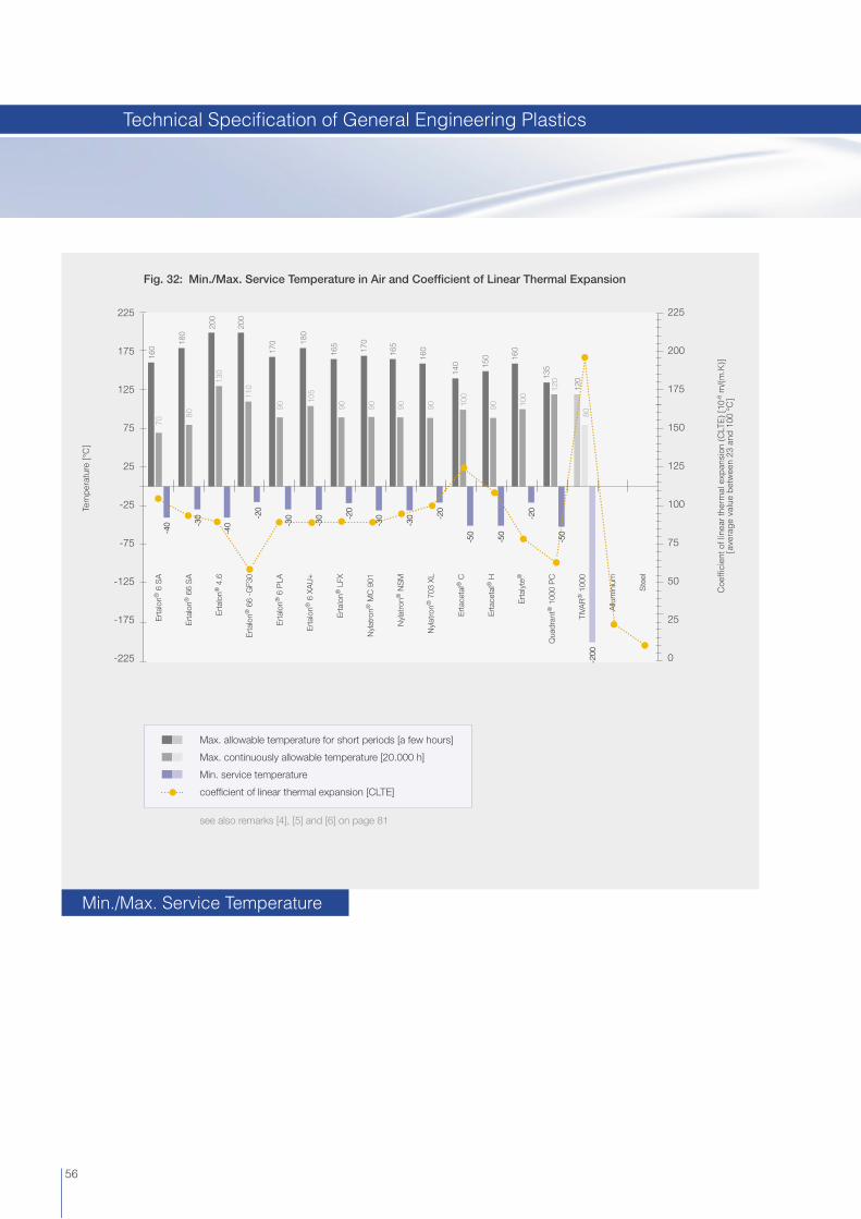
Fig. 32: Min./Max. Service Temperature in Air and Coeffi cient of Linear Thermal Expansion
225
175
125
75
25
-25
-75
-125
-175
-225
225
200
175
150
125
100
75
50
25
0
Coe
ffi ci
ent o
f lin
ear
ther
mal
exp
ansi
on (
CLT
E)
[10-6
m/(
m.K
)][a
vera
ge
valu
e b
etw
een
23 a
nd 1
00 °
C]
Tem
per
atur
e [°
C]
160
70
170
90
105
-40
180
80
200
130
200
110
180
9016
5
9017
0
9016
5
9016
0
100
140
9015
0
100
160
12013
5
8012
0
-40
-20
-30
-30 -2
0
-30
-30 -2
0
-50
-20
-50
-50
-200
Ert
alon
® 6
SA
Ert
alon
® 6
6 S
A
Ert
alon
® 4
.6
Ert
alon
® 6
6 -G
F30
Ert
alon
® 6
PLA
Ert
alon
® 6
XA
U+
Ert
alon
® L
FX
Nyl
atro
n® M
C 9
01
Nyl
atro
n® N
SM
Nyl
atro
n® 7
03 X
L
Ert
acet
al®
C
Ert
acet
al®
H
Ert
alyt
e®
Qua
dran
t® 1
000
PC
TIVA
R®
100
0
Allu
min
ium
Ste
el
-30
see also remarks [4], [5] and [6] on page 81
Max. allowable temperature for short periods [a few hours]
Max. continuously allowable temperature [20.000 h]
Min. service temperature
coeffi cient of linear thermal expansion [CLTE]
56
Min./Max. Service Temperature
Technical Specifi cation of General Engineering Plastics

Fig. 33: Stress Relaxation of Ertalyte® and Ertacetal® C at Different Temperatures Isometric Stress-Time Curves for a Deformation of 2 % [derived from tensile creep tests]
Tens
ile s
tress
[M
Pa]
60
50
40
30
20
10
00.1 1 10 100 1000
Loading time [hours]
Ertalyte®
Ertacetal® C
23 °C
80 °C
50 °C
50 °C
80 °C
23 °C
Fig. 34: Wear Resistance [measured on a “plastics pin on rotating steel disk” - tribo system]
Ert
alon
® 6
SA
Ert
alon
® 6
6 S
A
Ert
alon
® 4
.6
Ert
alon
® 6
6-G
F30
Nyl
atro
n® G
S
Ert
alon
® 6
PLA
Ert
alon
® 6
XA
U+
Ert
alon
® L
FX
Nyl
atro
n® M
C90
1
Nyl
atro
n® G
SM
Nyl
atro
n® N
SM
Nyl
atro
n® 7
03 X
L
Ert
acet
al®
C
Ert
acet
al®
H-T
F
Ert
alyt
e®
Ert
alyt
e® T
X
Qua
dran
t 100
0 P
C
TIVA
R®
100
0
Wea
r ra
te [
µm/k
m]
60
50
40
30
20
10
0
19
14
18
45
4.5
1211 12 11 12 11
4.52.5
8
3 2
3000
8
Test conditions:
pressure: 3 MPasliding velocity: 0.33 m/ssurface roughness of the C35 steel mating surface: Ra = 0.70 - 0.90 µmtotal distance run: 28 kmnormal environment [air, 23 °C / 50 % RH]unlubricated operation
57
Stress Relaxation
Wear Resistance
Technical Specifi cation of General Engineering Plastics

Fig. 35: Dynamic Coeffi cient of Friction [measured on a “plastics pin on rotating steel disk” - tribo system]
Ert
alon
® 6
SA
Ert
alon
® 6
6 S
A
Ert
alon
® 4
.6
Ert
alon
® 6
6-G
F30
Nyl
atro
n® G
S
Ert
alon
® 6
PLA
Ert
alon
® 6
XA
U+
Ert
alon
® L
FX
Nyl
atro
n® M
C90
1
Nyl
atro
n® G
SM
Nyl
atro
n® N
SM
Nyl
atro
n® 7
03 X
L
Ert
acet
al®
C
Ert
acet
al®
H-T
F
Ert
alyt
e®
Ert
alyt
e® T
X
Qua
dran
t 100
0 P
C
TIVA
R®
100
0
0,60
0,40
0,60
0,40
0,40
0,25
0,60
0,400,35
0,55
0,40
0,60
0,40
0,60
0,20
0,35 0,40
0,60
0,35
0,55
0,20
0,35
0,15
0,220,30
0,45 0,50
0,60
0,15
0,30
Dyn
amic
coe
ffi ci
ent o
f fric
tion
[-]
1,00
0,90
0,80
0,70
0,60
0,50
0,40
0,30
0,20
0,10
0,00
0,15
0,25
0,12
0,180,20
0,30
Test conditions:
pressure: 3 MPasliding velocity: 0.33 m/ssurface roughness of the C35 steel mating surface: Ra = 0.70 - 0.90 µmtotal distance run: 28 kmnormal environment [air, 23 °C / 50 % RH]unlubricated operation
58
Dynamic Coeffi cient of Friction
Technical Specifi cation of General Engineering Plastics

[*] The limiting PV-values given in the graph refer to properly designed plastics-metals combinations with excellent heat dissipation characteristics that operate continuously and without lubrication in a normal air environment of about 23 °C [e.g. a steel shaft rotating in a thin walled plastics bushing with a length to I.D. ratio of max. 1]. Obviously, higher pv-values can be allowed in case of intermittent or lubricated operation.
In many plastic bearing systems [sleeve-, slide bearings and thrust washers] it is the maximum occurring bearing temperature - which can be assessed by means of the so-called PV-value - that sets a limit to the load capacity. The PV-value is the product of the average bearing pressure P [MPa] and the relative velocity V [m/s] between the sliding partners. For a given construction, this pressure-velocity rating determines the quantity of heat generated by friction and therefore the bearing temperature. In order to obtain the longest possible and trouble free bearing life [without unallowable deformation, excessive wear or even melting], the bearing temperature and hence the PV-value should not exceed a certain limit. This limiting PV-value is often reported as one unique material property value although it varies e.g. as a function of speed and above all depends very much on the heat evacuation possibilities of the bearing system at hand. Consequently, published limiting PV-values can only give the designer a rough idea about the pressure- velocity capability of a plastics material. It is therefore often recommended to run a practical test under real operating conditions to assess the fi nal suitability of a chosen plastics material for the given application.
Fig. 36: Limiting PV-Values for Cylindrical Sleeve Bearings [*]
HIGHER IS BETTER
Lim
iting
PV-
valu
e [M
Pa.
m/s
]
0,5
0,4
0,3
0,2
0,1
0
Ert
alo
n®
6 S
A
Ert
alo
n®
66
SA
Ert
alo
n®
4.6
Ert
alo
n®
66
-GF3
0
Nyl
atro
n®
GS
Ert
alo
n®
6 P
LA
Ert
alo
n®
6 X
AU
+
Ert
alo
n®
LFX
Nyl
atro
n®
MC
90
1
Nyl
atro
n®
GS
M
Nyl
atro
n®
NS
M
Nyl
atro
n®
70
3 X
L
Ert
acet
al®
C
Ert
acet
al®
H
Ert
acet
al®
H-T
F
Ert
alyt
e®
Ert
alyt
e® T
X
TIV
AR
® 1
00
0
sliding velocity = 0.1 m/ssliding velocity = 1 m/s
59
PV-Values
Technical Specifi cation of General Engineering Plastics

60
TIVAR® | Ultra High Molecular Weight Polyethylene [PE-UHMW]TIVAR is the brand name of Quadrant Engineering Plastic Products for its extensive range of virgin, partially reprocessed, coloured or modifi ed Ultra High Molecular Weight Polyethylene stock shapes, manufactured by compression moulding or ram-extrusion. In less demanding applications with respect to wear and impact resistance, PE 500 may present an economical alternative for the TIVAR standard grades. It is a versatilepolyethylene grade used mainly in the food industry [meat and fi sh processing] but it is also employed in all kinds of mechanical, chemical and electrical applications.
Main Characteristics
Very good wear and abrasion resistance [particularly PE-UHMW] High impact strength, even at low temperatures [particularly PE-UHMW] Excellent chemical resistance Low density compared with other thermoplastics [≈ 1 g/cm3] Low coeffi cient of friction Excellent release properties Very low water absorption Moderate mechanical strength, stiffness and creep resistance Very good electrical insulating and dielectric properties [except static dissipative grades] Excellent machinability Physiologically inert [several grades have a food contact compliant composition] Good resistance to high energy radiation [gamma- and X-rays] Not self-extinguishing [except TIVAR Burnguard]
Applications
Gears, bearings, wear plates, support-, tension- and defl ecting rollers, rope pulleys, chain sprockets, bumpers, scraper blades, piston rings and packings, seals, valves, hammerheads, conveyor screws, star wheels and bends, corner tracks, parcel chutes, pumps, fi lter plates, pickers, beater caps, linings for bunkers, silos, chutes and funnels for bulk materials, punching plates, cutting and chopping boards
Standard Grades
TIVAR® 1000 [PE-UHMW; natural (white), green, black, colours - available as “Food Grade“, details see page 65]TIVAR 1000 exhibits a very well balanced property profi le. It combines a very good wear and abrasion resistance with an outstanding impact strength, even at temperatures below -200 °C.
TIVAR® 1000 antistatic [PE-UHMW + carbon black; black - available as “Food Grade“, details see page 65]By incorporating an effective carbon black grade, TIVAR 1000 antistatic offers the electrostatic dissipative properties often required for PE-UHMW components operating at high line speeds and conveying rates, maintaining the inherent key characteristics of PE-UHMW.
TIVAR® Ultra High Molecular Weight Polyethylene [PE-UHMW]
Polyethylene Grades for Low Temperature Range

61
TIVAR® ECO green [PE-UHMW; green]This grade, partially composed of reprocessed PE-UHMW material, has an overall lower property level than the virgin TIVAR 1000 and a lower cost. Compared with virgin PE 500, however, it has a much better impact strength and wear resistance. TIVAR ECO shows a favourable price-performance ratio for applications in many kinds of industries with less demanding requirements.
TIVAR® ECO black antistatic [PE-UHMW; black]This grade, partially composed of reprocessed PE-UHMW material, has an overall lower property level than the virgin TIVAR 1000 and a lower cost. Compared with virgin PE 500, however, it has a much better impact strength and wear resistance. The incorporation of an effective carbon black grade renders this material electrostatic dissipative properties. TIVAR ECO black antistatic shows a favourable price-performance ratio for applications in many kinds of industries with less demanding requirements.
Speciality Grades
Quadrant Engineering Plastic Products focuses on innovation by modifi cation of TIVAR 1000 standard materials in order to meet specifi c market requirements. The TIVAR Speciality Grades offer improved sliding and wear properties, static dissipative characteristics, enhanced release properties or other improved characteristics.
TIVAR® DrySlide [PE-UHMW + internal lubricant + other additives; black]Thanks to the lubricant built into a PE-UHMW matrix with higher molecular weight, TIVAR DrySlide offers a lower coeffi cient of friction and enhanced wear and abrasion resistance than TIVAR 1000. The additives used also make this material static dissipative and considerably improve UV-resistance.
TIVAR® TECH [PE-UHMW + MoS2; grey-black - available as “Food Grade“, details see page 65]This PE-UHMW grade with extremely high degree of polymerisation contains molybdenum disulphide, resulting in a material with improved wear resistance and sliding properties over TIVAR 1000.
TIVAR® DS [PE-UHMW + additives; grey, yellow - available as “Food Grade“, details see page 65]TIVAR DS is a modifi ed PE-UHMW with extremely high molecular weight. The latter in combination with a particular manufacturing process result in a PE-UHMW grade with superior wear and abrasion resistance over TIVAR 1000.
TIVAR® Ceram P [PE-UHMW + micro glass beads + other additives; yellow-green]TIVAR Ceram P is a wear improved PE-UHMW material with incorporated micro glass beads, specifi cally developed for use in the dewatering zone of paper machinery equipped with plastic wires and manufacturing paper with high abrasive fi ller content.
TIVAR® Ultra High Molecular Weight Polyethylene [PE-UHMW]
Polyethylene Grades for Low Temperature Range

62
TIVAR® SuperPlus [PE-UHMW + specifi c additives; grey]TIVAR SuperPlus is a wear optimised, partially cross-linked PE-UHMW material with extremely high degree of polymerisation for use in most demanding applications and environments. When used for drainage elements in paper machinery, this TIVAR-grade generally also offers better wear and sliding performance than TIVAR Ceram P.
TIVAR® H.O.T. [PE-UHMW + specifi c additives; bright white - available as “Food Grade“, details see page 65]TIVAR H.O.T. [Higher Operating Temperature] is formulated to maintain inherent PE-UHMW key properties over an extended service temperature range, in this way considerably increasing part life in low load bearing applications up to temperatures as high as 125 °C. Special additives reduce the oxidation rate of the material at higher temperatures thereby slowing down material degradation and extending wear-life. TIVAR H.O.T. also features a food contact compliant composition.
TIVAR® Burnguard [PE-UHMW + fl ame retardant + other additives; black with silver coloured spots]TIVAR Burnguard is a PE-UHMW grade containing a very effective non-halogenated fl ame retardant. Specifi cally developed to improve the poor fl ammability behaviour of straight forward virgin polyethylene, it meets the requirements of UL 94 V-0 as of 6 mm thickness and is selfextinguishing. The additives used also render this material static dissipative and considerably improve UV-resistance.
TIVAR® CleanStat [PE-UHMW + specifi c additives; black - available as “Food Grade“, details see page 65]TIVAR CleanStat is a PE-UHMW grade for use in food processing and pharmaceutical industries. It exhibits static dissipative properties and has a food contact compliant composition.
TIVAR® 1000 ASTL [PE-UHMW + specifi c additives; black - available as “Food Grade“, details see page 65]TIVAR 1000 ASTL, based on a PE-UHMW grade with extremely high molecular weight, has been specifi cally developed for tough anti-abrasion applications. TIVAR 1000 ASTL shows a higher wear and abrasion resistance and a lower surface resistivity than TIVAR 1000 antistatic. The additives used also render this material static dissipative and highly UV-resistant.
TIVAR® 1000 EC [PE-UHMW + specifi c additives; black - available as “Food Grade“, details see page 65]TIVAR 1000 EC is a PE-UHMW grade containing specifi c additives rendering this material a lower surface resistivity than TIVAR 1000 antistatic, improving electrical conductivity and UV-resistance.
TIVAR® MD [PE-UHMW + metal detectable additive; grey - available as “Food Grade“, details see page 65]This PE-UHMW grade with extremely high degree of polymerisation contains a metal detectable additive which does hardly affect the inherent PE-UHMW key properties. TIVAR MD presents excellent toughness and impact strength, an even improved wear and abrasion resistance when compared with TIVAR 1000, and it also features a food contact compliant composition. TIVAR MD has been specifi cally tailored for use in the food processing and packaging industries where it can easily be traced by the conventional metal detection systems installed to detect contamination of the foodstuffs [results may vary depending on the sensitivity of the metal detection system used].
TIVAR® Oil Filled [PE-UHMW + oil; grey]TIVAR Oil Filled is a self-lubricating PE-UHMW material in the real meaning of the word. Next to an enhanced wear resistance, the incorporated and evenly dispersed oil renders this material a considerable lower coeffi cient of friction than TIVAR 1000. In conveying equipment, it yields a signifi cant reduction of the required driving force and, in addition, noise reduction. TIVAR Oil Filled also offers an FDA food contact compliant composition.
TIVAR® Ultra High Molecular Weight Polyethylene [PE-UHMW]
Polyethylene Grades for Low Temperature Range
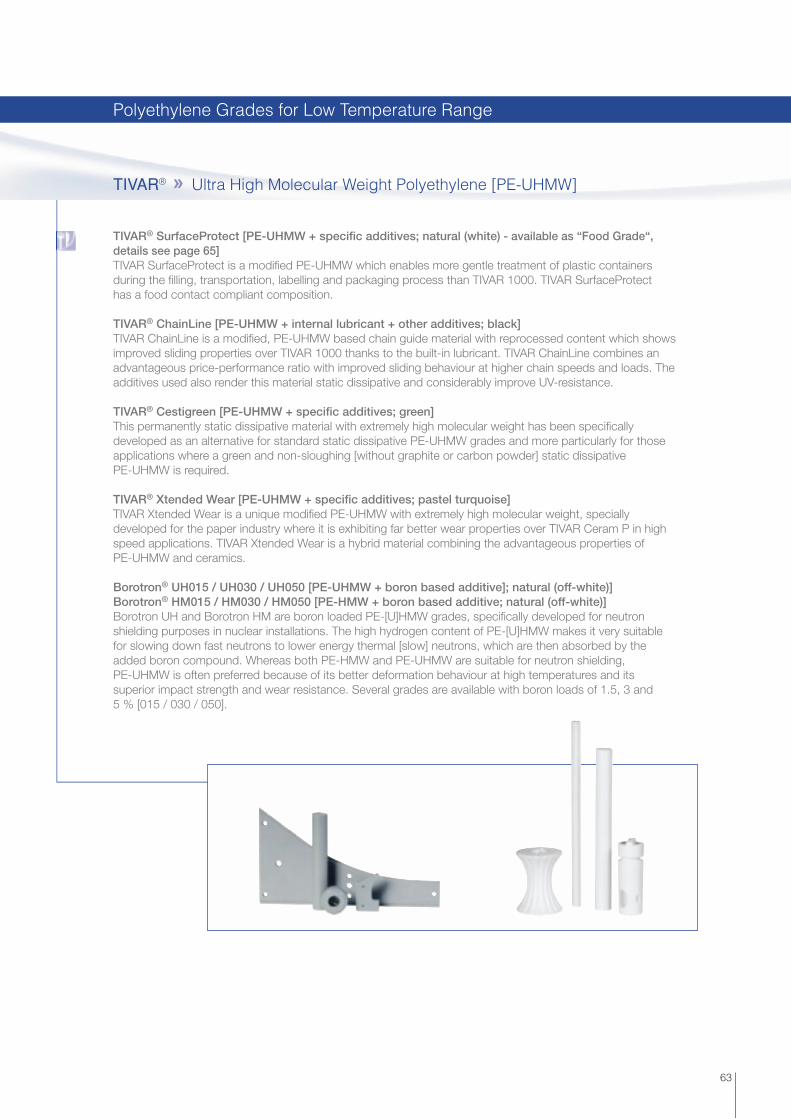
63
TIVAR® SurfaceProtect [PE-UHMW + specifi c additives; natural (white) - available as “Food Grade“, details see page 65]TIVAR SurfaceProtect is a modifi ed PE-UHMW which enables more gentle treatment of plastic containers during the fi lling, transportation, labelling and packaging process than TIVAR 1000. TIVAR SurfaceProtect has a food contact compliant composition.
TIVAR® ChainLine [PE-UHMW + internal lubricant + other additives; black]TIVAR ChainLine is a modifi ed, PE-UHMW based chain guide material with reprocessed content which shows improved sliding properties over TIVAR 1000 thanks to the built-in lubricant. TIVAR ChainLine combines an advantageous price-performance ratio with improved sliding behaviour at higher chain speeds and loads. The additives used also render this material static dissipative and considerably improve UV-resistance.
TIVAR® Cestigreen [PE-UHMW + specifi c additives; green]This permanently static dissipative material with extremely high molecular weight has been specifi cally developed as an alternative for standard static dissipative PE-UHMW grades and more particularly for those applications where a green and non-sloughing [without graphite or carbon powder] static dissipative PE-UHMW is required.
TIVAR® Xtended Wear [PE-UHMW + specifi c additives; pastel turquoise]TIVAR Xtended Wear is a unique modifi ed PE-UHMW with extremely high molecular weight, specially developed for the paper industry where it is exhibiting far better wear properties over TIVAR Ceram P in high speed applications. TIVAR Xtended Wear is a hybrid material combining the advantageous properties of PE-UHMW and ceramics.
Borotron® UH015 / UH030 / UH050 [PE-UHMW + boron based additive]; natural (off-white)]Borotron® HM015 / HM030 / HM050 [PE-HMW + boron based additive; natural (off-white)]Borotron UH and Borotron HM are boron loaded PE-[U]HMW grades, specifi cally developed for neutron shielding purposes in nuclear installations. The high hydrogen content of PE-[U]HMW makes it very suitable for slowing down fast neutrons to lower energy thermal [slow] neutrons, which are then absorbed by the added boron compound. Whereas both PE-HMW and PE-UHMW are suitable for neutron shielding, PE-UHMW is often preferred because of its better deformation behaviour at high temperatures and its superior impact strength and wear resistance. Several grades are available with boron loads of 1.5, 3 and 5 % [015 / 030 / 050].
TIVAR® Ultra High Molecular Weight Polyethylene [PE-UHMW]
Polyethylene Grades for Low Temperature Range

64
PE 500 [PE-HMW; natural (white), green, black, colours - available as “Food Grade“, details see page 65]This grade exhibits a good combination of stiffness, toughness, mechanical damping ability with wear- and abrasion resistance and can easily be welded. In less demanding applications with respect to wear and impact resistance, PE 500 may present an economical alternative for the TIVAR® standard grades.PE 500 is a versatile polyethylene grade used mainly in the food industry [meat and fi sh processing] but it is also put to use in all kinds of mechanical, chemical and electrical applications.
[1] average molecular weight [106 g/mol]
Abbreviations: SDA: static dissipative additive; GB: glass beads; IL: internal lubricant(s); HS: heat stabiliser; FR: fl ame retardant; MDA: metal detectable additive
Selection Table
Features
Products
Mol. weight[1] Colours Additives
Sliding properties
[coeff.of friction]
Wear resistance[plasticspin
on steeldisk]
Abrasion resistance[sand-slurry]
UV- resistance
ESd- properties
TIVAR® 1000 5 natural, green, black, colours none or pigments good good good moderate no
TIVAR® 1000 antistatic 5 black SDA good good good good yes
TIVAR® ECO green ≥ 4.5 green pigments good moderate moderate moderate no
TIVAR® ECO black antistatic ≥ 4.5 black pigments good moderate moderate moderate yes
TIVAR® DrySlide 9 black IL + SDA very good very good very good good yes
TIVAR® TECH 9 grey-black MoS2 good excellent very good moderate no
TIVAR® DS 9 yellow, grey pigments good very good very good moderate no
TIVAR® Ceram P 9 yellow-green GB + pigments good excellent excellent moderate no
TIVAR® SuperPlus 9 grey IL + pigments + other good excellent excellent moderate no
TIVAR® H.O.T. 9 bright-white HS + pigments good very good excellent moderate no
TIVAR® Burnguard 5 black FR good good moderate good yes
TIVAR® CleanStat 5 black SDA good good very good good yes
TIVAR® 1000 ASTL 9 black SDA good very good very good very good yes
TIVAR® 1000 EC 5 black SDA good good good very good yes
TIVAR® MD 9 grey MDA good very good excellent moderate no
Borotron® UH 5 natural B2O3 good good moderate moderate no
Borotron® HM 0.5 natural B2O3 good poor poor moderate no
TIVAR® Oil Filled 9 grey oil + pigments excellent very good very good moderate no
TIVAR® SurfaceProtect 5 natural IL very good moderate good moderate no
TIVAR® ChainLine ≥ 4.5 black IL + SDA very good good good good yes
TIVAR® Cestigreen 9 green SDA + pigments good very good very good moderate yes
TIVAR® Xtended Wear 9 light grey minerals + pigments good excellent good moderate no
PE 500 0.5 natural, green, black, colours none or pigments good poor poor moderate no
PE 500 High Molecular Weight Polyethylene [PE-HMW]
Polyethylene Grades for Low Temperature Range
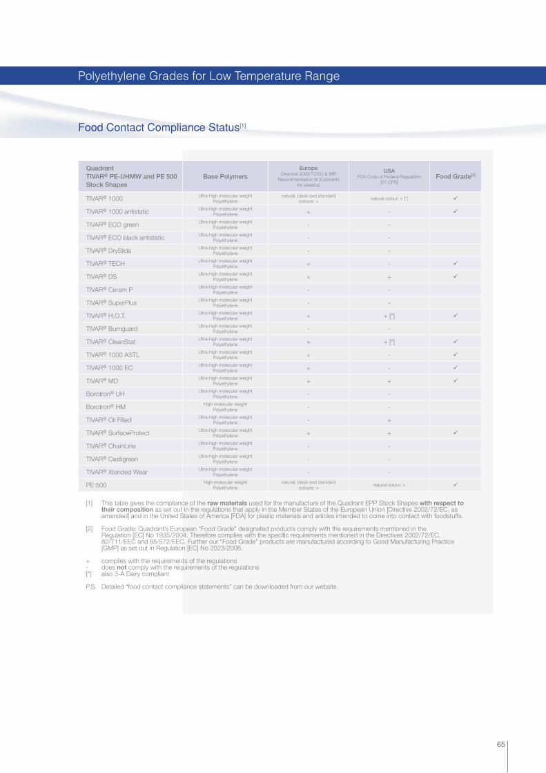
QuadrantTIVAR® PE-UHMW and PE 500 Stock Shapes
Base PolymersEurope
Directive 2002/72/EC & BfR Recommendation IX (Colorants
for plastics)
USAFDA Code of Federal Regulation
[21 CFR]Food Grade[2]
TIVAR® 1000 Ultra-high molecular weightPolyethylene
natural, black and standard colours: +
natural colour: + [*] ü
TIVAR® 1000 antistatic Ultra-high molecular weightPolyethylene + - ü
TIVAR® ECO green Ultra-high molecular weightPolyethylene - -
TIVAR® ECO black antistatic Ultra-high molecular weightPolyethylene - -
TIVAR® DrySlide Ultra-high molecular weightPolyethylene - -
TIVAR® TECH Ultra-high molecular weightPolyethylene + - ü
TIVAR® DS Ultra-high molecular weightPolyethylene + + ü
TIVAR® Ceram P Ultra-high molecular weightPolyethylene - -
TIVAR® SuperPlus Ultra-high molecular weightPolyethylene - -
TIVAR® H.O.T. Ultra-high molecular weightPolyethylene + + [*] ü
TIVAR® Burnguard Ultra-high molecular weightPolyethylene - -
TIVAR® CleanStat Ultra-high molecular weightPolyethylene + + [*] ü
TIVAR® 1000 ASTL Ultra-high molecular weightPolyethylene + - ü
TIVAR® 1000 EC Ultra-high molecular weightPolyethylene + - ü
TIVAR® MD Ultra-high molecular weightPolyethylene + + ü
Borotron® UH Ultra-high molecular weightPolyethylene - -
Borotron® HM High molecular weightPolyethylene - -
TIVAR® Oil Filled Ultra-high molecular weightPolyethylene - +
TIVAR® SurfaceProtect Ultra-high molecular weightPolyethylene + + ü
TIVAR® ChainLine Ultra-high molecular weightPolyethylene - -
TIVAR® Cestigreen Ultra-high molecular weightPolyethylene - -
TIVAR® Xtended Wear Ultra-high molecular weightPolyethylene - -
PE 500 High molecular weightPolyethylene
natural, black and standard colours: +
natural colour: + ü
65
[1] This table gives the compliance of the raw materials used for the manufacture of the Quadrant EPP Stock Shapes with respect to their composition as set out in the regulations that apply in the Member States of the European Union [Directive 2002/72/EC, as amended] and in the United States of America [FDA] for plastic materials and articles intended to come into contact with foodstuffs.
[2] Food Grade: Quadrant’s European “Food Grade” designated products comply with the requirements mentioned in the Regulation [EC] No 1935/2004. Therefore complies with the specifi c requirements mentioned in the Directives 2002/72/EC, 82/711/EEC and 85/572/EEC. Further our “Food Grade” products are manufactured according to Good Manufacturing Practice [GMP] as set out in Regulation [EC] No 2023/2006.
+ complies with the requirements of the regulations- does not comply with the requirements of the regulations[*] also 3-A Dairy compliant
P.S. Detailed “food contact compliance statements” can be downloaded from our website.
Food Contact Compliance Status[1]
Polyethylene Grades for Low Temperature Range

Tens
ile s
tres
s [M
Pa]
Fig. 37: Tensile Stress-Strain Curves of TIVAR® 1000 at Different Temperatures [tested acc. to ISO 527; test specimens: Type 1B; test speed: 50 mm/min.]
Tensile strain [%]
35
30
25
20
15
10
5
0403020100 50
Tens
ile s
tres
s at
yie
ld [M
Pa]
Fig. 38: Tensile Stress at Yield of PE 500 and TIVAR® 1000 as a Function of Temperature [acc. to ISO 527; test specimens: Type 1B; test speed: 50 mm/min.]
50
40
30
20
10
0
Temperature [°C]
-40 -10-20-30 40 10030 9020 80100 50 7060
TIVAR® 1000PE 500
-30 °C
23 °C
60 °C
120 °C
66
Tensile Stress
Tensile Stress
Technical Specifi cation of Polyethylene Grades

Not
ched
impa
ct s
tren
gth
[kJ/
m2 ]
Fig. 40: Charpy Notched Impact Strength of TIVAR® 1000 as a Function of Temperature [acc. to ISO 11542-2; double 14° notch]
200
150
100
50
0
-200 500-50-100-150 100
Temperature [°C]
Mod
ulus
of e
last
icity
[M
Pa]
Fig. 39: Stiffness of PE 500 and TIVAR® 1000 as a Function of Temperature [derived from DMA-curves]
2000
1800
1600
1400
1200
1000
800
600
400
200
0
Temperature [°C]
-40-50 -10-20-30 40 10030 9020 80100 50 7060
TIVAR® 1000PE 500
67
Stiffness
Impact Strength [Charpy]
Technical Specifi cation of Polyethylene Grades
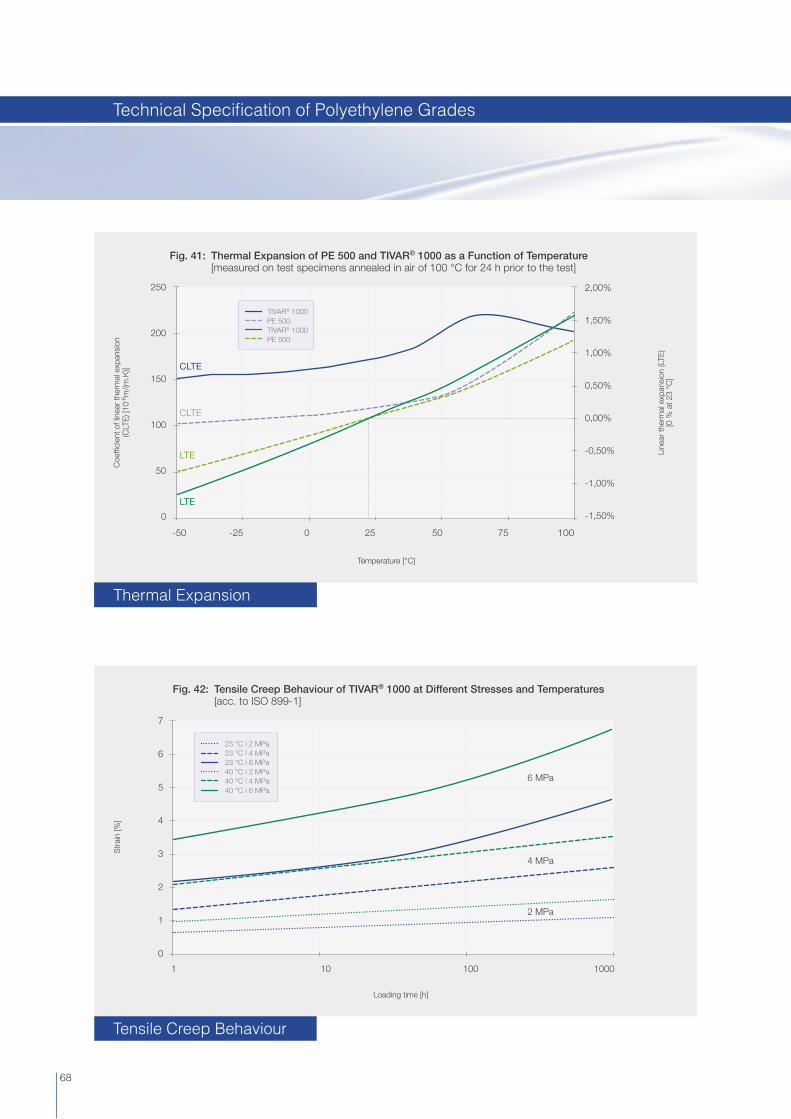
Line
ar th
erm
al e
xpan
sion
(LTE
) [0
% a
t 23
°C]
Fig. 41: Thermal Expansion of PE 500 and TIVAR® 1000 as a Function of Temperature [measured on test specimens annealed in air of 100 °C for 24 h prior to the test]
Str
ain
[%]
Fig. 42: Tensile Creep Behaviour of TIVAR® 1000 at Different Stresses and Temperatures [acc. to ISO 899-1]
7
6
5
4
3
2
1
0
Loading time [h]
1 1000100
6 MPa
4 MPa
2 MPa
10
23 °C | 2 MPa23 °C | 4 MPa23 °C | 6 MPa40 °C | 2 MPa40 °C | 4 MPa40 °C | 6 MPa
Coe
ffi ci
ent o
f lin
ear
ther
mal
exp
ansi
on
(CLT
E) [
10-6
m/(m
.K)]
Temperature [°C]
250
200
150
100
50
0
50250-25-50 75 100
2,00%
1,50%
1,00%
0,50%
0,00%
-0,50%
-1,00%
-1,50%
CLTE
CLTE
LTE
LTE
TIVAR® 1000PE 500TIVAR® 1000PE 500
68
Thermal Expansion
Tensile Creep Behaviour
Technical Specifi cation of Polyethylene Grades

Fig. 43: Abrasion Resistance at 23 °C [derived from „sand/water-slurry“ tests]
PE
500
TIVA
R® 1
000
TIVA
R® 1
000
antis
tatic
TIVA
R® E
CO
gre
en
TIVA
R® E
CO
bla
ck a
ntis
tatic
TIVA
R® D
ryS
lide
TIVA
R® T
EC
H
TIVA
R® D
S
TIVA
R® C
eram
P
TIVA
R® S
uper
Plu
s
TIVA
R® H
.O.T
.
TIVA
R® B
urng
uard
TIVA
R® C
lean
Sta
t
TIVA
R® 1
000
AS
TL
TIVA
R® 1
000
EC
TIVA
R® M
D
Bor
otro
n® H
M 0
15
Bor
otro
n® U
H 0
15
TIVA
R® O
il Fi
lled
TIVA
R® S
urfa
ceP
rote
ct
TIVA
R® C
hain
Line
TIVA
R® C
estig
reen
TIVA
R® X
tend
ed W
ear
PV
C
PTF
E
PA 6
Bea
chw
ood
Ste
el 3
7
Rel
ativ
e vo
lum
e lo
ss [
TIVA
R 1
000
= 1
00]
400
350
300
250
200
150
100
50
0
400
350
300
250
200
150
100
50
0
100 100 100105
200
225
250
2700530900
160
85 8585 8595 90
130 130 130135
808075 7585
200
350
LOWER IS BETTER
250
2700530900
160
69
Abrasion Resistance
Technical Specifi cation of Polyethylene Grades
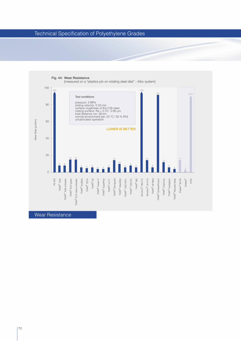
Fig. 44: Wear Resistance [measured on a “plastics pin on rotating steel disk” - tribo system]
Wea
r R
ate
[µm
/km
]
100
80
60
40
20
0
8 86 5 6 66 6 6 6
4 44 3
15 15 14 1412
14
108
300 15090 1600
Test conditions:
pressure: 3 MPasliding velocity: 0.33 m/ssurface roughness of the C35 steelmating surface: Ra = 0.70 - 0.90 µmtotal distance run: 28 kmnormal environment [air, 23 °C / 50 % RH]unlubricated operation
3
14
1600
LOWER IS BETTER
PE
500
TIVA
R® 1
000
TIVA
R® 1
000
antis
tatic
TIVA
R® E
CO
gre
en
TIVA
R® E
CO
bla
ck a
ntis
tatic
TIVA
R® D
ryS
lide
TIVA
R® T
EC
H
TIVA
R® D
S
TIVA
R® C
eram
P
TIVA
R® S
uper
Plu
s
TIVA
R® H
.O.T
.
TIVA
R® B
urng
uard
TIVA
R® C
lean
Sta
t
TIVA
R® 1
000
AS
TL
TIVA
R® 1
000
EC
TIVA
R® M
D
Bor
otro
n® H
M 0
15
Bor
otro
n® U
H 0
15
TIVA
R® O
il Fi
lled
TIVA
R® S
urfa
ceP
rote
ct
TIVA
R® C
hain
Line
TIVA
R® C
estig
reen
TIVA
R® X
tend
ed W
ear
Ert
alon
® 6
6 S
A
Ert
alyt
e®
PTF
E
70
Wear Resistance
Technical Specifi cation of Polyethylene Grades

Fig. 45: Dynamic Coeffi cient of Friction [measured on a “plastics pin on rotating steel disk” - tribo system]
Dyn
amic
coe
ffi ci
ent o
f fric
tion
[-]
0,7
0,6
0,5
0,4
0,3
0,2
0,1
0
0,30 0,30
0,15 0,15
0,30
0,35 0,35
0,60
0,30 0,30 0,30 0,30
0,15
0,20 0,20
0,40
0,15 0,15 0,15 0,15
0,30 0,30 0,30 0,30
0,15 0,15 0,15 0,15
0,30
0,27
0,30 0,30
0,15 0,15 0,15 0,15
0,30
0,25 0,25
0,22
0,25 0,25
0,20
0,30
0,15 0,15 0,15
0,12
0,15 0,15
0,10
0,15
Test conditions:
pressure: 3 MPasliding velocity: 0.33 m/ssurface roughness of the C35 steel mating surface: Ra = 0.70 - 0.90 µmtotal distance run: 28 kmnormal environment [air, 23 °C / 50 % RH]unlubricated operation
0,60
0,40
0,25
0,20
0,15
0,10
PE
500
TIVA
R® 1
000
TIVA
R® 1
000
antis
tatic
TIVA
R® E
CO
gre
en
TIVA
R® E
CO
bla
ck a
ntis
tatic
TIVA
R® D
ryS
lide
TIVA
R® T
EC
H
TIVA
R® D
S
TIVA
R® C
eram
P
TIVA
R® S
uper
Plu
s
TIVA
R® H
.O.T
.
TIVA
R® B
urng
uard
TIVA
R® C
lean
Sta
t
TIVA
R® 1
000
AS
TL
TIVA
R® 1
000
EC
TIVA
R® M
D
Bor
otro
n® H
M 0
15
Bor
otro
n® U
H 0
15
TIVA
R® O
il Fi
lled
TIVA
R® S
urfa
ceP
rote
ct
TIVA
R® C
hain
Line
TIVA
R® C
estig
reen
TIVA
R® X
tend
ed W
ear
Ert
alon
® 6
6 S
A
Ert
alyt
e®
PTF
E
71
Dynamic Coeffi cient of Friction
Technical Specifi cation of Polyethylene Grades

72
Quadrant EPP offers Life Science Grades which have been specifi cally developed for applications in the medical, pharmaceutical and biotechnology industries. The QEPP Life Science Grades portfolio includes plastics which comply with FDA, ISO 10993 and USP guidelines for biocompatibility testing of materials – saving testing costs and time – while providing full traceability from raw material to stock shape.
Key benefi ts of the Life Science Grades are:
PerformanceUsing the cutting edge material portfolio from Quadrant will replace existing solutions made of stainless steel, Titanium and glass or ceramics due to a combination of properties like weight reduction, resistance to commonly used sterilisation methods, X-ray transparency, design fl exibility, antistatic performance and resistance to high energetic radiation.
BiocompatibilityThe LSG portfolio includes plastics which comply with FDA , ISO 10993 and USP guidelines for biocompatibility testing of materials.
Full traceabilityQuadrant provides OEMs with assurance of full traceability for its comprehensive LSG product porfolio.
Quality assuranceIn line with its ISO 9001:2000 certifi ed Quality Assurance System, Quadrant EPP thorougly monitors and controls the entire manufacturing process of its Life Science Grades.
Life Science Grades [LSG]

73
Biocompatibility Status USP and ISO 10993A comprehensive biocompatibility type testing programme was run by an independent, internationally renowned and accredited testing organisation on the Quadrant LSG stock shapes in order to check their compliance with both United States Pharmacopeia [USP] and ISO 10993-1 guideline requirements for Biocompatibility Testing of Materials.
Quadrant Engineering Plastic Products makes no warranties or representations whatsoever that its materials are manufactured in accordance with the quality standards appropriate and necessary for materials intended for use in implantable medical device applications and in applications that are essential to the restoration or continuation of a bodily function important to the continuation of human life.
Quadrant‘s Life Science Grades should not be used for applications involving medical devices that are intended to remain implanted in the human body continuously for a period exceeding 24 hours [30 days*], or that are intended to remain in contact with internal human tissue or bodily fl uids for more than 24 hours [30 days*]. They should not be used either for the manufacture of critical components of medical devices that are essential to the continuation of human life.
*: ‘30 days’ applies to Ketron® CLASSIXTM LSG PEEK white only.
• This test was carried out and the material passed the test. NT Not Tested[1] All tests were run on test specimens machined from rod diameter 50 mm shortly after manufacture. [2] Quadrant EPP performs testing on its Life Science Grades in order to facilitate evaluation by its customers of their biocompatibility with regard to the requirements applicable to the specifi c use of the fi nished product. Quadrant EPP does not possess expertise in evaluating the suitability of its tested materials for use in specifi c medical, pharmaceutical or biotechnological applications. It remains the customer’s sole responsibility to test and assess the suitability of Quadrant’s Life Science Grades for its intended applications, processes and uses. [3] Please note that the virgin, natural coloured POM Copolymer resins used in the manufacture of the Acetron® LSG natural & black stock shapes meet the requirements of USP Class VI [according to biocompatibility tests carried out on behalf of the resin suppliers].
Ketron® CLASSIXTM LSG PEEK white • • • • • • • • •
Ketron® LSG CA30 PEEK • • • • • • • • •
Ketron® LSG GF30 PEEK blue [RAL 5019] • • • • • • • • •
Ketron® LSG PEEK natural & black • • • • • • • • •
Quadrant® LSG PPSU black • • • • • • • • •
Quadrant® LSG PPSU natural [ivory] • NT • • NT NT • • NT
Quadrant® LSG PPSU blue, green, grey, red, yellow • NT NT NT NT NT • • NT
Duratron® LSG PEI natural • • • • • • • • •
Quadrant® LSG PSU natural • • • • • • • • •
Quadrant® LSG PC natural • • • • • • • • •
Acetron® LSG natural & black • NT NT NT NT NT • • NT [3]
Materials
Test[1] [2]
1. C
yto
toxi
city
Ref
.: IS
O 1
0993
-5 a
nd U
SP
<87
> B
iolo
gica
l R
eact
ivity
Tes
ts, I
n V
itro
- E
lutio
n Te
st
2. S
ensi
tizat
ion
Ref
. IS
O 1
0993
-10,
Mag
nuss
on &
Klig
man
M
axim
izat
ion
Met
hod
3. In
trac
utan
eous
Rea
ctiv
ity
Ref
.: IS
O 1
0993
-10
and
US
P <
88>
Bio
logi
cal
Rea
ctiv
ity T
ests
, In
Viv
o -
Intr
acut
aneo
us T
est
4. S
yste
mic
To
xici
ty
Ref
.: IS
O 1
0993
-11
and
US
P <
88>
Bio
logi
ca
Rea
ctiv
ity T
ests
, In
Viv
o -
Sys
tem
ic In
ject
ion
Test
5. Im
pla
ntat
ion
Test
Ref
.: U
SP
<88
> B
iolo
gica
l Rea
ctiv
ity T
ests
, In
Viv
o -
Impl
anta
tion
Test
[7 d
ays]
6. H
uman
blo
od
co
mp
atib
ility
Ref
.: IS
O 1
0993
-4, I
ndire
ct H
emol
ysis
[in
vitr
o]
7. U
SP
-Phy
sico
chem
ical
Tes
ts f
or
Pla
stic
s
Ref
.: U
SP
<66
1> C
onta
iner
s, U
ltra
Pur
e W
ater
ex
trac
t, 70
°C
/ 2
4 h
8. H
eavy
met
al c
ont
ent
[mg
/kg
]
Test
ing
the
cont
ent o
f cad
miu
m, c
hrom
ium
, lea
d an
d m
ercu
ry b
y m
eans
of I
CP
-MS
US
P C
lass
VI
[co
nclu
sio
n fr
om
tes
ts 3
, 4 a
nd 5
]
Biocompatibility Testing
Life Science Grades [LSG]
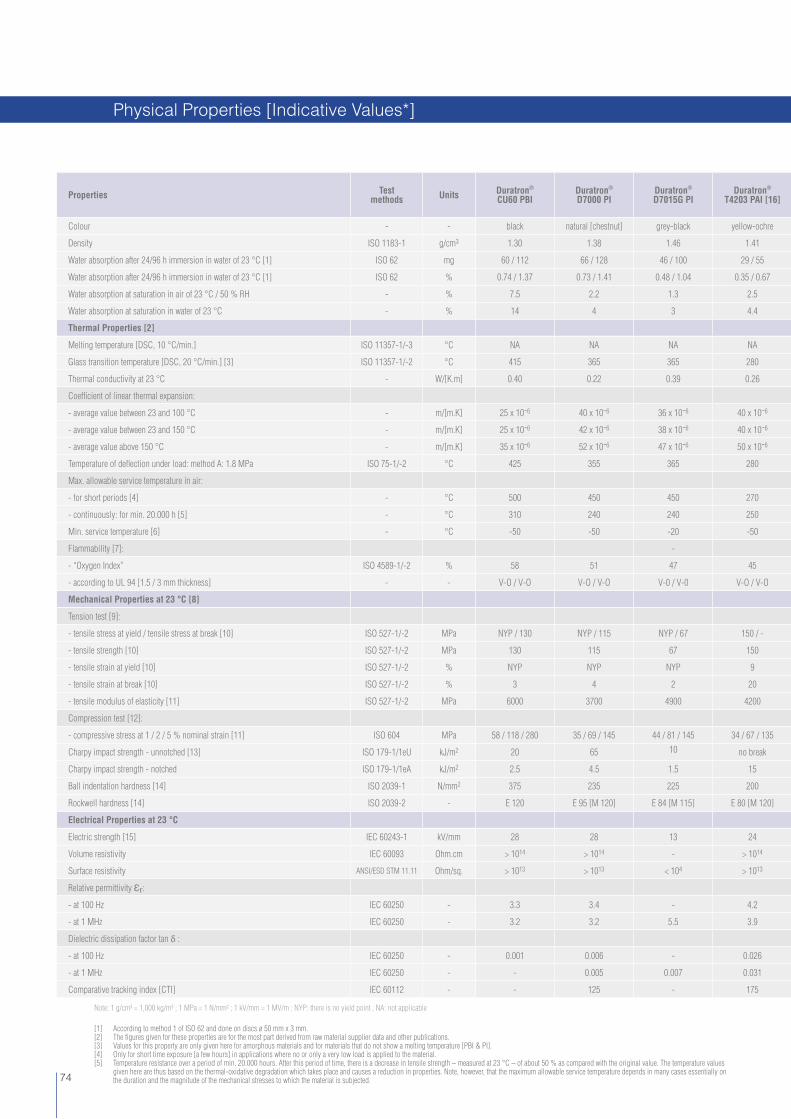
74
Properties Test methods Units Duratron®
CU60 PBIDuratron® D7000 PI
Duratron®
D7015G PIDuratron®
T4203 PAI [16]
Colour - - black natural [chestnut] grey-black yellow-ochre
Density ISO 1183-1 g/cm3 1.30 1.38 1.46 1.41
Water absorption after 24/96 h immersion in water of 23 °C [1] ISO 62 mg 60 / 112 66 / 128 46 / 100 29 / 55
Water absorption after 24/96 h immersion in water of 23 °C [1] ISO 62 % 0.74 / 1.37 0.73 / 1.41 0.48 / 1.04 0.35 / 0.67
Water absorption at saturation in air of 23 °C / 50 % RH - % 7.5 2.2 1.3 2.5
Water absorption at saturation in water of 23 °C - % 14 4 3 4.4
Thermal Properties [2]
Melting temperature [DSC, 10 °C/min.] ISO 11357-1/-3 °C NA NA NA NA
Glass transition temperature [DSC, 20 °C/min.] [3] ISO 11357-1/-2 °C 415 365 365 280
Thermal conductivity at 23 °C - W/[K.m] 0.40 0.22 0.39 0.26
Coeffi cient of linear thermal expansion:
- average value between 23 and 100 °C - m/[m.K] 25 x 10-6 40 x 10-6 36 x 10-6 40 x 10-6
- average value between 23 and 150 °C - m/[m.K] 25 x 10-6 42 x 10-6 38 x 10-6 40 x 10-6
- average value above 150 °C - m/[m.K] 35 x 10-6 52 x 10-6 47 x 10-6 50 x 10-6
Temperature of defl ection under load: method A: 1.8 MPa ISO 75-1/-2 °C 425 355 365 280
Max. allowable service temperature in air:
- for short periods [4] - °C 500 450 450 270
- continuously: for min. 20.000 h [5] - °C 310 240 240 250
Min. service temperature [6] - °C -50 -50 -20 -50
Flammability [7]: -
- “Oxygen Index” ISO 4589-1/-2 % 58 51 47 45
- according to UL 94 [1.5 / 3 mm thickness] - - V-O / V-O V-O / V-O V-0 / V-0 V-O / V-O
Mechanical Properties at 23 °C [8]
Tension test [9]:
- tensile stress at yield / tensile stress at break [10] ISO 527-1/-2 MPa NYP / 130 NYP / 115 NYP / 67 150 / -
- tensile strength [10] ISO 527-1/-2 MPa 130 115 67 150
- tensile strain at yield [10] ISO 527-1/-2 % NYP NYP NYP 9
- tensile strain at break [10] ISO 527-1/-2 % 3 4 2 20
- tensile modulus of elasticity [11] ISO 527-1/-2 MPa 6000 3700 4900 4200
Compression test [12]:
- compressive stress at 1 / 2 / 5 % nominal strain [11] ISO 604 MPa 58 / 118 / 280 35 / 69 / 145 44 / 81 / 145 34 / 67 / 135
Charpy impact strength - unnotched [13] ISO 179-1/1eU kJ/m2 20 65 10 no break
Charpy impact strength - notched ISO 179-1/1eA kJ/m2 2.5 4.5 1.5 15
Ball indentation hardness [14] ISO 2039-1 N/mm2 375 235 225 200
Rockwell hardness [14] ISO 2039-2 - E 120 E 95 [M 120] E 84 [M 115] E 80 [M 120]
Electrical Properties at 23 °C
Electric strength [15] IEC 60243-1 kV/mm 28 28 13 24
Volume resistivity IEC 60093 Ohm.cm > 1014 > 1014 - > 1014
Surface resistivity ANSI/ESD STM 11.11 Ohm/sq. > 1013 > 1013 < 104 > 1013
Relative permittivity Ɛr:
- at 100 Hz IEC 60250 - 3.3 3.4 - 4.2
- at 1 MHz IEC 60250 - 3.2 3.2 5.5 3.9
Dielectric dissipation factor tan δ :
- at 100 Hz IEC 60250 - 0.001 0.006 - 0.026
- at 1 MHz IEC 60250 - - 0.005 0.007 0.031
Comparative tracking index [CTI] IEC 60112 - - 125 - 175
Note: 1 g/cm³ = 1,000 kg/m³ ; 1 MPa = 1 N/mm² ; 1 kV/mm = 1 MV/m ; NYP: there is no yield point ; NA: not applicable
[1] According to method 1 of ISO 62 and done on discs ø 50 mm x 3 mm.[2] The fi gures given for these properties are for the most part derived from raw material supplier data and other publications.[3] Values for this property are only given here for amorphous materials and for materials that do not show a melting temperature [PBI & PI].[4] Only for short time exposure [a few hours] in applications where no or only a very low load is applied to the material.[5] Temperature resistance over a period of min. 20.000 hours. After this period of time, there is a decrease in tensile strength – measured at 23 °C – of about 50 % as compared with the original value. The temperature values given here are thus based on the thermal-oxidative degradation which takes place and causes a reduction in properties. Note, however, that the maximum allowable service temperature depends in many cases essentially on the duration and the magnitude of the mechanical stresses to which the material is subjected.
Physical Properties [Indicative Values*]

75
Duratron® T4301 PAI [16]
Duratron® T5530 PAI
Ketron® 1000 PEEK
Ketron® HPV PEEK
Ketron® GF30 PEEK
Ketron® CA30 PEEK
Ketron® TX PEEK
Techtron® PPS
Techtron® HPV PPS
Quadrant® PPSU
black khaki-grey natural [brownish grey] black black natural [brownish grey] black blue natural [cream] deep blue black
1.45 1.61 1.31 1.45 1.51 1.40 1.39 1.35 1.42 1.29
26 / 48 25 / 50 5 / 10 4 / 9 5 / 10 4 / 9 4 / 9 1 / 2 1 / 2 25 / 54
0.30 / 0.55 0.26 / 0.52 0.06 / 0.12 0.05 / 0.11 0.05 / 0.10 0.05 / 0.11 0.05 / 0.10 0.01 / 0.02 0.01 / 0.02 0.30 / 0.65
1.9 1.7 0.20 0.16 0.16 0.16 0.18 0.03 0.05 0.50
3.8 3.2 0.45 0.35 0.35 0.35 0.40 0.10 0.20 1.10
NA NA 340 340 340 340 340 280 280 NA
280 280 - - - - - - - 220
0.54 0.36 0.25 0.78 0.43 0.92 0.25 0.30 0.30 0.30
35 x 10-6 35 x 10-6 50 x 10-6 35 x 10-6 30 x 10-6 25 x 10-6 55 x 10-6 60 x 10-6 50 x 10-6 55 x 10-6
35 x 10-6 35 x 10-6 55 x 10-6 40 x 10-6 30 x 10-6 25 x 10-6 60 x 10-6 80 x 10-6 60 x 10-6 55 x 10-6
40 x 10-6 40 x 10-6 130 x 10-6 85 x 10-6 65 x 10-6 55 x 10-6 140 x 10-6 145 x 10-6 100 x 10-6 65 x 10-6
280 280 160 195 230 260 155 115 115 205
270 270 310 310 310 310 310 260 260 210
250 250 250 250 250 250 250 220 220 180
-20 -20 -50 -20 -20 -20 - 20 -30 -20 -50
44 50 35 43 40 40 40 44 44 38
V-O / V-O V-O / V-O V-0 / V-0 V-0 / V-0 V-0 / V-0 V-0 / V-0 V-0 / V-0 V-0 / V-0 V-0 / V-0 V-0 / V-0
NYP / 110 NYP / 125 115 / - NYP / 78 80 / - NYP / 144 90 / - 102 / - NYP / 78 83 / -
110 125 115 78 80 144 90 102 78 83
NYP NYP 5 NYP 3.5 NYP 5 3.5 NYP 8
5 3 17 3 4.5 4 6 12 3.5 > 50
5500 6400 4300 5900 7000 9200 3750 4000 4000 2450
39 / 72 / 130 55 / 104 / 190 38 / 75 / 140 46 / 80 / 120 54 / 103 / 155 69 / 125 / 170 31 / 61 / 120 39 / 77 / 122 33 / 65 / 105 21 / 41 / 83
45 30 no break 25 25 50 30 no break 25 no break
4 3.5 3.5 3 3 5 3 2 4 12
200 275 210 215 250 310 195 205 160 95
M 106 [E 70] E 85 [M 125] M 105 M 85 M 100 M 102 M 97 M 100 M 82 M 90
- 28 24 - 24 - 22 18 24 26
> 1013 > 1014 > 1014 - > 1014 < 105 > 1014 > 1014 > 1014 > 1014
> 1013 > 1013 > 1013 - > 1013 < 105 > 1013 > 1013 > 1013 > 1013
6.0 4.4 3.2 - 3.2 - 3.2 3.0 3.3 3.4
5.4 4.2 3.2 - 3.6 - 3.2 3.0 3.3 3.5
0.037 0.022 0.001 - 0.001 - 0.001 0.002 0.003 0.001
0.042 0.050 0.002 - 0.002 - 0.002 0.002 0.003 0.005
175 175 150 - 175 - 150 125 100 < 100
[6] Impact strength decreasing with decreasing temperature, the minimum allowable service temperature is practically mainly determined by the extent to which the material is subjected to impact. The values given here are based on unfavourable impact conditions and may consequently not be considered as being the absolute practical limits.[7] These estimated ratings, derived from raw material supplier data and other publications, are not intended to refl ect hazards presented by the materials under actual fi re conditions. There are no ‘UL File Numbers‘ available for the Advanced Engineering Plastic stock shapes.[8] Most of the fi gures given for the mechanical properties of the extruded materials are average values of tests run on dry test specimens machined out of rod Ø 40 - 60 mm. Except for the hardness tests, the test specimens were then taken from an area mid between centre and outside diameter, with their length in longitudinal direction of the rod [parallel to the extrusion direction]. [9] Test specimens: Type 1 B
Advanced Engineering Plastic Stock Shapes

76
[10] Test speed: 5 or 50 mm/min. [chosen acc. to ISO 10350-1 as a function of the ductile behaviour of the material [tough or brittle] ; all materials showing a tensile strain at break ≥ 10% were tested at 50 mm/min.[11] Test speed: 1 mm/min.[12] Test specimens: cylinders ø 8 mm x 16 mm[13] Pendulum used: 4 J[14] Measured on 10 mm thick test specimens [discs], mid between centre and outside diameter[15] Electrode confi guration: ø 25 mm / ø 75 mm coaxial cylinders; in transformer oil according to IEC 60296; 1 mm thick test specimens. Please note that the electric strength of Ketron® 1000 PEEK black and Quadrant® PPSU black can be considerably lower than the fi gures listed in the table which refer to natural material.
Properties Test methods Units Quadrant®
1000 PSUDuratron® U1000 PEI
Symalit®
1000 PVDFSymalit®
1000 ECTFE
Colour - - natural [yellow, translucent] natural [amber, translucent] natural [white] natural [cream]
Density ISO 1183-1 g/cm3 1.24 1.27 1.78 1.68
Water absorption after 24/96 h immersion in water of 23 °C [1] ISO 62 mg 19 / 38 16 / 34 1 / 3 0.7 / 1.5
Water absorption after 24/96 h immersion in water of 23 °C [1] ISO 62 % 0.24 / 0.48 0.19 / 0.40 0.01 / 0.03 0.006 / 0.013
Water absorption at saturation in air of 23 °C / 50 % RH - % 0.30 0.70 0.05 0.04
Water absorption at saturation in water of 23 °C - % 0.80 1.30 < 0.10 < 0.10
Thermal Properties [2]
Melting temperature [DSC, 10 °C/min.] ISO 11357-1/-3 °C NA NA 175 240
Glass transition temperature [DSC, 20 °C/min.] [3] ISO 11357-1/-2 °C 190 215 - -
Thermal conductivity at 23 °C - W/[K.m] 0.26 0.24 0.19 0.15
Coeffi cient of linear thermal expansion:
- average value between 23 and 100 °C - m/[m.K] 55 x 10-6 50 x 10-6 190 x 10-6 120 x 10-6
- average value between 23 and 150 °C - m/[m.K] 55 x 10-6 50 x 10-6 220 x 10-6 140 x 10-6
- average value above 150 °C - m/[m.K] 70 x 10-6 60 x 10-6 - 220 x 10-6
Temperature of defl ection under load: method A: 1.8 MPa ISO 75-1/-2 °C 170 195 105 65
Max. allowable service temperature in air:
- for short periods [4] - °C 180 200 160 180
- continuously: for min. 20.000 h [5] - °C 150 170 150 160
Min. service temperature [6] - °C -50 -50 -50 -200
Flammability [7]:
- “Oxygen Index” ISO 4589-1/-2 % 30 47 44 52
- according to UL 94 [1.5 / 3 mm thickness] - - HB / HB V-0 / V-0 V-0 / V-0 V-0 / V-0
Mechanical Properties at 23 °C [8]
Tension test [9]:
- tensile stress at yield / tensile stress at break [10] ISO 527-1/-2 MPa 88 / - 129 / - 60 / - 30 / -
- tensile strength [10] ISO 527-1/-2 MPa 88 129 60 48
- tensile strain at yield [10] ISO 527-1/-2 % 5 7 9 4
- tensile strain at break [10] ISO 527-1/-2 % 10 13 30 > 50
- tensile modulus of elasticity [11] ISO 527-1/-2 MPa 2850 3500 2200 1600
Compression test [12]:
- compressive stress at 1 / 2 / 5 % nominal strain [11] ISO 604 MPa 25 / 49 / 101 31 / 61 / 137 20 / 36 / 62 14.5 / 26 / 33
Charpy impact strength - unnotched [13] ISO 179-1/1eU kJ/m2 no break no break no break no break
Charpy impact strength - notched ISO 179-1/1eA kJ/m2 3.5 3.5 10 180P
Ball indentation hardness [14] ISO 2039-1 N/mm2 115 165 110 65
Rockwell hardness [14] ISO 2039-2 - M 89 M 115 M 78 R 94
Electrical Properties at 23 °C
Electric strength [15] IEC 60243-1 kV/mm 30 27 18 26
Volume resistivity IEC 60093 Ohm.cm > 1014 > 1014 > 1014 > 1014
Surface resistivity ANSI/ESD STM 11.11 Ohm/sq. > 1013 > 1013 > 1013 > 1013
Relative permittivity Ɛr:
- at 100 Hz IEC 60250 - 3.0 3.0 7.4 2.5
- at 1 MHz IEC 60250 - 3.0 3.0 6.0 2.6
Dielectric dissipation factor tan δ :
- at 100 Hz IEC 60250 - 0.001 0.002 0.025 0.001
- at 1 MHz IEC 60250 - 0.003 0.002 0.165 0.015
Comparative tracking index [CTI] IEC 60112 - 150 175 600 600
Note: 1 g/cm³ = 1,000 kg/m³ ; 1 MPa = 1 N/mm² ; 1 kV/mm = 1 MV/m ; NYP: there is no yield point ; NA: not applicable
Physical Properties [Indicative Values*]

77
[16] It has to be noted that the property values of compression moulded Duratron® T4503 PAI, resp. Duratron® T4501 PAI stock shapes can signifi cantly differ from those given in this table for extruded Duratron® T4203 PAI, resp. Duratron® T4301 PAI stock shapes. They have to be considered on an individual shape and dimension related basis. Please consult us.
• This table, mainly to be used for comparison purposes, is a valuable help in the choice of a material. The data listed here fall within the normal range of product properties of dry material. However, they are not guaranteed and they should not be used to establish material specifi cation limits nor used alone as the basis of design. It has to be noted that several of the products listed in this table are fi bre reinforced and/or fi lled, and hence show an anisotropic behaviour [properties differ when measured parallel and perpendicular to the extrusion or compression direction].
Symalit®
1000 PFAFluorosint®
500Fluorosint®
207Fluorosint®
HPVFluorosint®
MT-01 Semitron® ESd 225
Semitron® ESd 410C
Semitron® ESd 500HR
Semitron® ESd 520HR
natural [white] ivory white tan dark grey beige black white khaki grey
2.14 2.32 2.30 2.06 2.27 1.33 1.41 2.30 1.58
0.6 / 1.4 - / - - / - 10 / 20 - / - 392 / 705 - - / - 56 / 110
0.004 / 0.010 - / - - / - 0.07 / 0.15 - / - 5 / 9 - - / - 0.60 / 1.18
0.01 < 0.1 < 0.1 0.1 - 0.2 - 0.8 0.60 < 0.1 2.6
< 0.03 1.5 - 2.5 1 - 2 0.5 - 1 1.5 - 2.5 10 1.10 1 - 2 4.6
305 327 327 327 327 165 NA 327 NA
- - - - - - 215 - 280
0.20 0.77 - - - - 0.35 - 0.34
135 x 10-6 50 x 10-6 85 x 10-6 75 x 10-6 60 x 10-6 150 x 10-6 40 x 10-6 85 x 10-6 35 x 10-6
150 x 10-6 55 x 10-6 90 x 10-6 80 x 10-6 65 x 10-6 - 40 x 10-6 90 x 10-6 35 x 10-6
250 x 10-6 85 x 10-6 155 x 10-6 135 x 10-6 100 x 10-6 - 45 x 10-6 155 x 10-6 40 x 10-6
40 130 100 80 95 - 200 100 280
280 280 280 280 300 140 200 280 270
250 260 260 260 260 90 170 260 250
-200 -20 -50 -50 -20 -50 -20 -50 -20
≥ 95 ≥ 95 ≥ 95 ≥ 95 ≥ 95 < 20 47 ≥ 95 48
V-0 / V-0 V-0 / V-0 V-0 / V-0 V-0 / V-0 V-0 / V-0 HB / HB V-0 / V-0 V-0 / V-0 V-0 / V-0
15 / - 7 / - 10 / - 10 / - 14 / - NYP / 38 NYP / 62 10 / - NYP / 83
30 7 10 10 14 38 62 10 83
50 5 4 6 6 NYP NYP 4 NYP
> 50 15 > 50 > 50 20 15 2 > 50 3
575 1750 1450 1200 1900 1500 5850 1450 5500
5.5 / 10 / 16 12 / 19 / 25 10.5 / 15 / 20 10 / 14.5 / 19 11 / 17 / 29 14 / 25 / 38 44 / 76 / 114 10.5 / 15 / 20 42 / 80 / 145
no break 8 30 55 20 no break 20 30 20
75P 4.5 7.5 12 4 8 4 7.5 4
35 60 40 45 55 70 - 40 250
R 70 R 55 R 50 R 45 R 74 R 106 M 115 R 50 M 110 [E 73]
35 11 8 - - - - - -
> 1014 > 1013 > 1013 - - 109 - 1011 104 - 106 1010 - 1012 1010 - 1012
> 1013 > 1013 > 1013 > 1013 < 105 109 - 1011 104 - 106 1010 - 1012 1010 - 1012
2.1 - - - - - - - -
2.1 2.85 2.65 - - 4.3 3.0 3.1 5.8
< 0.0005 - - - - - - - -
< 0.0005 0.008 0.008 - - 0.036 0.002 0.075 0.18
600 - - - - - - - -
Advanced Engineering Plastic Stock Shapes

78
Properties Test methods Units Nylatron®
MDAcetron®
MDErtalon®
6 SAErtalon®
66 SA
Colour - - dark blue blue natural [white]/ black natural [cream], blackDensity ISO 1183-1 g/cm3 1.21 1.46 1.14 1.14Water absorption after 24/96 h immersion in water of 23 °C [1] ISO 62 mg 60 / 118 19/37 86 / 168 40 / 76Water absorption after 24/96 h immersion in water of 23 °C [1] ISO 62 % 0.78 / 1.53 0.21 / 0.40 1.28 / 2.50 0.60 / 1.13Water absorption at saturation in air of 23 °C / 50 % RH - % 2.5 0.19 2.6 2.4
Water absorption at saturation in water of 23 °C - % 6.9 0.75 9 8
Thermal Properties [2]Melting temperature [DSC, 10 °C/min.] ISO 11357-1/-3 °C 220 165 220 260Glass transition temperature [DSC, 20 °C/min.] [3] ISO 11357-1/-2 °C - - - -Thermal conductivity at 23 °C - W/[K.m] 0.28 0.31 0.28 0.28Coeffi cient of linear thermal expansion:- average value between 23 and 60 °C - m/[m.K] 85 x 10-6 115 x 10-6 90 x 10-6 80 x 10-6
- average value between 23 and 100 °C - m/[m.K] 100 x 10-6 130 x 10-6 105 x 10-6 95 x 10-6
Temperature of defl ection under load: method A: 1.8 MPa ISO 75-1/-2 °C 85 100 70 85Max. allowable service temperature in air:- for short periods [4] - °C 160 140 160 180- continuously: for 5.000 / 20.000 h [5] - °C 85/70 105/90 85/70 95/80Min. service temperature [6] - °C -25 -30 -40 -30Flammability [7]:- “Oxygen Index” ISO 4589-1/-2 % 25 < 20 25 26- according to UL 94 [3 / 6 mm thickness] - - HB / HB HB / HB HB / HB HB / HBMechanical Properties at 23 °C [8]Tension test [9]:- tensile stress at yield / tensile stress at break [10] ISO 527-1/-2 MPa 87 / - 66 / - 80 / - 90 / - ISO 527-1/-2 MPa 50 / - 66 / - 45 / - 55 / -- tensile strength [10] ISO 527-1/-2 MPa 87 66 80 93- tensile strain at yield [10] ISO 527-1/-2 % 4 14 4 5- tensile strain at break [10] ISO 527-1/-2 % 25 15 > 50 50 ISO 527-1/-2 % > 50 15 > 100 > 100- tensile modulus of elasticity [11] ISO 527-1/-2 MPa 4000 2950 3300 3550 ISO 527-1/-2 MPa 1800 2950 1425 1700Compression test [12]:- compressive stress at 1 / 2 / 5 % nominal strain [11] ISO 604 MPa 35 / 67 / 92 25 / 44 / 76 31 / 59 / 87 32 / 62 / 100Charpy impact strength - unnotched [13] ISO 179-1/1eU kJ/m2 80 70 no break no breakCharpy impact strength - notched ISO 179-1/1eA kJ/m2 3 5 5.5 4.5Ball indentation hardness [14] ISO 2039-1 N/mm2 170 155 150 160Rockwell hardness [14] ISO 2039-2 - M 85 M 86 M 85 M 88Electrical Properties at 23 °C Electric strength [15] IEC 60243-1 kV/mm - - 25 27 IEC 60243-1 kV/mm - - 16 18Volume resistivity IEC 60093 Ohm.cm > 1012 > 1013 > 1014 > 1014
IEC 60093 Ohm.cm > 1010 > 1013 > 1012 > 1012
Surface resistivity IEC 60093 Ohm > 1011 > 1012 > 1013 > 1013
IEC 60093 Ohm > 1010 > 1012 > 1012 > 1012
Relative permittivity Ɛr: - at 100 Hz IEC 60250 - - - 3.9 3.8 IEC 60250 - - - 7.4 7.4- at 1 MHz IEC 60250 - - - 3.3 3.3
IEC 60250 - - - 3.8 3.8Dielectric dissipation factor tan δ :- at 100 Hz IEC 60250 - - - 0.019 0.013 IEC 60250 - - - 0.13 0.13- at 1 MHz IEC 60250 - - - 0.021 0.020 IEC 60250 - - - 0.06 0.06Comparative tracking index [CTI] IEC 60112 - - - 600 600 IEC 60112 - - - 600 600Note: 1 g/cm³ = 1,000 kg/m³ ; 1 MPa = 1 N/mm² ; 1 kV/mm = 1 MV/m ; NYP: there is no yield point ;
+: values referring to dry material; ++: values referring to material in equilibrium with the standard atmosphere 23 °C / 50 % RH [mostly derived from literature]
+
+++
+++
+++
++
+++++
+++
+++
+++
+++
+++
+++
+++
+++
Physical Properties [Indicative Values*]

79
Ertalon® 66 SA-C
Ertalon® 4.6
Ertalon® 66-GF30
Nylatron® GS
Ertalon® 6 PLA
Ertalon® 6 XAU +
Ertalon® LFX
Nylatron® MC 901
Nylatron® GSM
Nylatron® NSM
natural [white] reddish brown black grey-black natural [ivory] black black green blue grey-black grey1.14 1.19 1.29 1.15 1.15 1.15 1.135 1.15 1.16 1.14
65 / 120 90 / 180 30 / 56 46 / 85 44 / 83 47 / 89 44 / 83 49 / 93 52 / 98 40 / 760.97 / 1.79 1.30 / 2.60 0.39 / 0.74 0.68 / 1.25 0.65 / 1.22 0.69 / 1.31 0.66 / 1.24 0.72 / 1.37 0.76 / 1.43 0.59 / 1.12
2.5 2.8 1.7 2.3 2.2 2.2 2 2.3 2.4 2
8.5 9.5 5.5 7.8 6.5 6.5 6.3 6.6 6.7 6.3
240 290 260 260 215 215 215 215 215 215- - - - - - - - - -
0.28 0.30 0.30 0.29 0.29 0.29 0.28 0.29 0.30 0.29
85 x 10-6 80 x 10-6 50 x 10-6 80 x 10-6 80 x 10-6 80 x 10-6 80 x 10-6 80 x 10-6 80 x 10-6 80 x 10-6
100 x 10-6 90 x 10-6 60 x 10-6 90 x 10-6 90 x 10-6 90 x 10-6 90 x 10-6 90 x 10-6 90 x 10-6 95 x 10-6
75 160 150 85 80 80 75 80 80 75
170 200 200 180 170 180 165 170 170 16590/75 150/130 120/110 95/80 105/90 120/105 105/90 105/90 105/90 105/90-30 -40 -20 -20 -30 -30 -20 -30 -30 -30
24 24 - 26 25 25 - 25 25 -HB / HB HB / HB HB / HB HB / HB HB / HB HB / HB HB / HB HB / HB HB / HB HB / HB
86 / - 105 / - NYP / 85 93 / - 86 / - 84 / - 72 / - 82 / - 80 / - 78 / -50 / - 55 / - - 55 / - 55 / - 55 / - 45 / - 50 / - 50 / - 50 / -
86 105 85 95 88 86 73 84 82 805 18 NYP 5 5 5 5 5 5 5
> 50 25 5 20 25 25 25 35 25 25> 100 > 50 - > 50 > 50 > 50 > 50 > 50 > 50 > 503350 3400 5000 3600 3600 3500 3000 3300 3400 31501475 1350 2700 1725 1750 1700 1450 1600 1650 1525
31 / 60 / 89 31 / 60 / 102 43 / 77 / 112 32 / 62 / 100 34 / 64 / 93 34 / 64 / 93 31 / 58 / 85 32 / 61 / 90 33 / 62 / 91 31 / 59 / 87no break no break 50 no break no break no break 50 no break no break 75
5 8 6 4 3 3 4 3 3 3.5155 165 165 165 165 165 145 160 160 150
M 87 M 92 M 76 M 88 M 88 M 87 M 82 M 85 M 84 M 81
26 25 27 26 25 29 22 25 24 2517 15 18 17 17 19 14 17 16 17
> 1014 > 1014 > 1014 > 1014 > 1014 > 1014 > 1014 > 1014 > 1014 > 1014
> 1012 > 1012 > 1012 > 1012 > 1012 > 1012 > 1012 > 1012 > 1012 > 1012
> 1013 > 1013 > 1013 > 1013 > 1013 > 1013 > 1013 > 1013 > 1013 > 1013
> 1012 > 1012 > 1012 > 1012 > 1012 > 1012 > 1012 > 1012 > 1012 > 1012
3.8 3.8 3.9 3.8 3.6 3.6 3.5 3.6 3.6 3.67.4 7.4 6.9 7.4 6.6 6.6 6.5 6.6 6.6 6.63.3 3.4 3.6 3.3 3.2 3.2 3.1 3.2 3.2 3.23.8 3.8 3.9 3.8 3.7 3.7 3.6 3.7 3.7 3.7
0.013 0.009 0.012 0.013 0.012 0.015 0.015 0.012 0.012 0.0120.13 0.13 0.19 0.13 0.14 0.15 0.15 0.14 0.14 0.14
0.020 0.019 0.014 0.020 0.016 0.017 0.016 0.016 0.016 0.0160.06 0.06 0.04 0.06 0.05 0.05 0.05 0.05 0.05 0.05600 400 475 600 600 600 600 600 600 600600 400 475 600 600 600 600 600 600 600
General Engineering Plastic Stock Shapes

80
Note: 1 g/cm³ = 1,000 kg/m³ ; 1 MPa = 1 N/mm² ; 1 kV/mm = 1 MV/m ; NYP: there is no yield point ;
+: values referring to dry material; ++: values referring to material in equilibrium with the standard atmosphere 23 °C / 50 % RH [mostly derived from literature]
Properties Test methods Units Nylatron®
LFGNylatron®
703 XL Ertacetal® C Ertacetal® H
Colour - - natural [ivory] blue purple natural [white]/black natural [white]/ black Density ISO 1183-1 g/cm3 1.135 1.11 1.41 1.43Water absorption after 24/96 h immersion in water of 23 °C [1] ISO 62 mg 44 / 83 40 / 76 20 / 37 18 / 36Water absorption after 24/96 h immersion in water of 23 °C [1] ISO 62 % 0.66 / 1.24 0.61 / 1.16 0.24 / 0.45 0.21 / 0.43Water absorption at saturation in air of 23 °C / 50 % RH - % 2 2 0.20 0.20Water absorption at saturation in water of 23 °C - % 6.3 6.3 0.80 0.80Thermal Properties [2]Melting temperature [DSC, 10°C/min.] ISO 11357-1/-3 °C 215 215 165 180Glass transition temperature [DSC, 20 °C/min.] [3] ISO 11357-1/-2 °C - - - -Thermal conductivity at 23 °C - W/[K.m] 0.28 0.30 0.31 0.31Coeffi cient of linear thermal expansion:- average value between 23 and 60 °C - m/[m.K] 80 x 10-6 85 x 10-6 110 x 10-6 95 x 10-6
- average value between 23 and 100 °C - m/[m.K] 90 x 10-6 100 x 10-6 125 x 10-6 110 x 10-6
Temperature of defl ection under load: method A: 1.8 MPa ISO 75-1/-2 °C 75 70 100 110Max. allowable service temperature in air:- for short periods [4] - °C 165 160 140 150- continuously: for 5.000 / 20.000 h [5] - °C 105/90 105/90 115/100 105/90Min. service temperature [6] - °C -20 -20 -50 -50Flammability [7]:- “Oxygen Index” ISO 4589-1/-2 % - < 20 15 15- according to UL 94 [3 / 6 mm thickness] - - HB / HB HB / HB HB / HB HB / HBMechanical Properties at 23 °C [8]Tension test [9]:- tensile stress at yield / tensile stress at break [10] ISO 527-1/-2 MPa 72 / - 60 / - 66 / - 78 / - ISO 527-1/-2 MPa 45 / - 40 / - 66 / - 78 / -- tensile strength [10] ISO 527-1/-2 MPa 73 60 66 78- tensile strain at yield [10] ISO 527-1/-2 % 5 6 20 40- tensile strain at break [10] ISO 527-1/-2 % 25 15 50 50 ISO 527-1/-2 % > 50 > 25 50 50- tensile modulus of elasticity [11] ISO 527-1/-2 MPa 3000 2750 2800 3300 ISO 527-1/-2 MPa 1450 1350 2800 3300Compression test [12]:- compressive stress at 1 / 2 / 5 % nominal strain [11] ISO 604 MPa 31 / 58 / 85 26 / 48 / 69 23 / 40 / 72 29 / 49 / 85Charpy impact strength - unnotched [13] ISO 179-1/1eU kJ/m2 50 25 no break no breakCharpy impact strength - notched ISO 179-1/1eA kJ/m2 4 4 8 10Ball indentation hardness [14] ISO 2039-1 N/mm2 145 120 140 160Rockwell hardness [14] ISO 2039-2 - M 82 R 109 [M 59] M 84 M 88Electrical Properties at 23 °C Electric strength [15] IEC 60243-1 kV/mm 22 - 20 20
IEC 60243-1 kV/mm 14 - 20 20Volume resistivity IEC 60093 Ohm.cm > 1014 > 1014 > 1014 > 1014
IEC 60093 Ohm.cm > 1012 > 1012 > 1014 > 1014
Surface resistivity IEC 60093 Ohm > 1013 > 1013 > 1013 > 1013
IEC 60093 Ohm > 1012 > 1012 > 1013 > 1013
Relative permittivity Ɛr: - at 100 Hz IEC 60250 - 3.5 - 3.8 3.8 IEC 60250 - 6.5 - 3.8 3.8- at 1 MHz IEC 60250 - 3.1 - 3.8 3.8 IEC 60250 - 3.6 - 3.8 3.8Dielectric dissipation factor tan δ :- at 100 Hz IEC 60250 - 0.015 - 0.003 0.003 IEC 60250 - 0.15 - 0.003 0.003- at 1 MHz IEC 60250 - 0.016 - 0.008 0.008
IEC 60250 - 0.05 - 0.008 0.008Comparative tracking index [CTI] IEC 60112 - 600 - 600 600
IEC 60112 - 600 - 600 600
+
+++
+++
+++
++
+++++
+++
+++
+++
+++
+++
+++
+++
+++
Physical Properties [Indicative Values*]
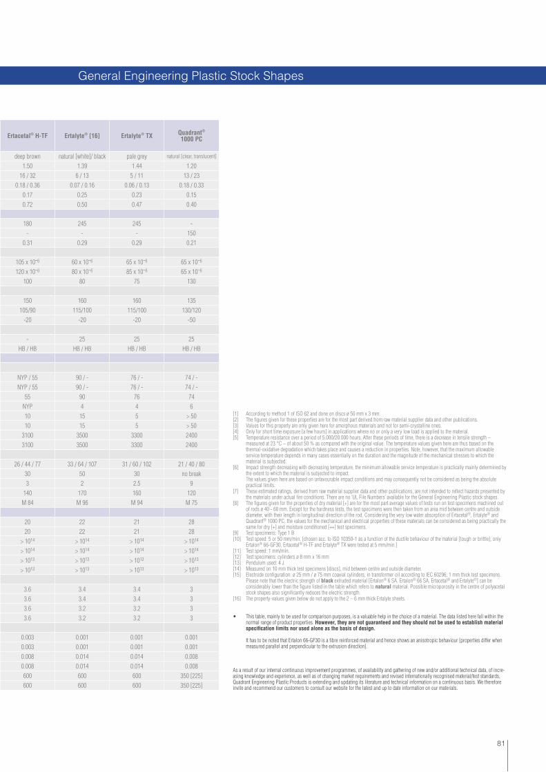
81
[1] According to method 1 of ISO 62 and done on discs ø 50 mm x 3 mm.[2] The fi gures given for these properties are for the most part derived from raw material supplier data and other publications.[3] Values for this property are only given here for amorphous materials and not for semi-crystalline ones.[4] Only for short time exposure [a few hours] in applications where no or only a very low load is applied to the material.[5] Temperature resistance over a period of 5.000/20.000 hours. After these periods of time, there is a decrease in tensile strength – measured at 23 °C – of about 50 % as compared with the original value. The temperature values given here are thus based on the thermal-oxidative degradation which takes place and causes a reduction in properties. Note, however, that the maximum allowable service temperature depends in many cases essentially on the duration and the magnitude of the mechanical stresses to which the material is subjected.[6] Impact strength decreasing with decreasing temperature, the minimum allowable service temperature is practically mainly determined by the extent to which the material is subjected to impact. The values given here are based on unfavourable impact conditions and may consequently not be considered as being the absolute practical limits.[7] These estimated ratings, derived from raw material supplier data and other publications, are not intended to refl ect hazards presented by the materials under actual fi re conditions. There are no ‘UL File Numbers’ available for the General Engineering Plastic stock shapes.[8] The fi gures given for the properties of dry material [+] are for the most part average values of tests run on test specimens machined out of rods ø 40 - 60 mm. Except for the hardness tests, the test specimens were then taken from an area mid between centre and outside diameter, with their length in longitudinal direction of the rod. Considering the very low water absorption of Ertacetal®, Ertalyte® and Quadrant® 1000 PC, the values for the mechanical and electrical properties of these materials can be considered as being practically the same for dry [+] and moisture conditioned [++] test specimens.[9] Test specimens: Type 1 B[10] Test speed: 5 or 50 mm/min. [chosen acc. to ISO 10350-1 as a function of the ductile behaviour of the material [tough or brittle]; only Ertalon® 66-GF30, Ertacetal® H-TF and Ertalyte® TX were tested at 5 mm/min.][11] Test speed: 1 mm/min.[12] Test specimens: cylinders ø 8 mm x 16 mm[13] Pendulum used: 4 J[14] Measured on 10 mm thick test specimens [discs], mid between centre and outside diameter.[15] Electrode confi guration: ø 25 mm / ø 75 mm coaxial cylinders; in transformer oil according to IEC 60296; 1 mm thick test specimens. Please note that the electric strength of black extruded material [Ertalon® 6 SA, Ertalon® 66 SA, Ertacetal® and Ertalyte®] can be considerably lower than the fi gure listed in the table which refers to natural material. Possible microporosity in the centre of polyacetal stock shapes also signifi cantly reduces the electric strength.[16] The property-values given below do not apply to the 2 – 6 mm thick Ertalyte sheets.
• This table, mainly to be used for comparison purposes, is a valuable help in the choice of a material. The data listed here fall within the normal range of product properties. However, they are not guaranteed and they should not be used to establish material specifi cation limits nor used alone as the basis of design.
It has to be noted that Ertalon 66-GF30 is a fi bre reinforced material and hence shows an anisotropic behaviour [properties differ when measured parallel and perpendicular to the extrusion direction].
As a result of our internal continuous improvement programmes, of availability and gathering of new and/or additional technical data, of incre-asing knowledge and experience, as well as of changing market requirements and revised internationally recognised material/test standards, Quadrant Engineering Plastic Products is extending and updating its literature and technical information on a continuous basis. We therefore invite and recommend our customers to consult our website for the latest and up to date information on our materials.
Ertacetal® H-TF Ertalyte® [16] Ertalyte® TX Quadrant®
1000 PC
deep brown natural [white]/ black pale grey natural [clear, translucent]
1.50 1.39 1.44 1.2016 / 32 6 / 13 5 / 11 13 / 23
0.18 / 0.36 0.07 / 0.16 0.06 / 0.13 0.18 / 0.330.17 0.25 0.23 0.150.72 0.50 0.47 0.40
180 245 245 -- - - 150
0.31 0.29 0.29 0.21
105 x 10-6 60 x 10-6 65 x 10-6 65 x 10-6
120 x 10-6 80 x 10-6 85 x 10-6 65 x 10-6
100 80 75 130
150 160 160 135105/90 115/100 115/100 130/120
-20 -20 -20 -50
- 25 25 25HB / HB HB / HB HB / HB HB / HB
NYP / 55 90 / - 76 / - 74 / -NYP / 55 90 / - 76 / - 74 / -
55 90 76 74NYP 4 4 610 15 5 > 5010 15 5 > 50
3100 3500 3300 24003100 3500 3300 2400
26 / 44 / 77 33 / 64 / 107 31 / 60 / 102 21 / 40 / 8030 50 30 no break3 2 2.5 9
140 170 160 120M 84 M 96 M 94 M 75
20 22 21 2820 22 21 28
> 1014 > 1014 > 1014 > 1014
> 1014 > 1014 > 1014 > 1014
> 1013 > 1013 > 1013 > 1013
> 1013 > 1013 > 1013 > 1013
3.6 3.4 3.4 33.6 3.4 3.4 33.6 3.2 3.2 33.6 3.2 3.2 3
0.003 0.001 0.001 0.0010.003 0.001 0.001 0.0010.008 0.014 0.014 0.0080.008 0.014 0.014 0.008600 600 600 350 [225]600 600 600 350 [225]
General Engineering Plastic Stock Shapes

82
Note: 1 g/cm³ = 1,000 kg/m³ ; 1 MPa = 1 N/mm² ; 1 kV/mm = 1 MV/m
[1] These are the average molar masses of the PE-[U]HMW resins [irrespective of any additives] used for the manufacture of the materials. They are calculated by means of the Margolies-equation M = 5.37 x 10⁴ x [ƞ]1.49, with [ƞ] being the intrinsic viscosity [Staudinger index] derived from a viscosity measurement according to ISO 1628-3:2001, using decahydronaphtalene as a solvent [concentration of 0.001 g/cm³ for PE-HMW and 0.0002 g/cm³ for PE-UHMW].[2] The fi gures given for these properties are for the most part derived from raw material supplier data and other publications.[3] Only for short time exposure [a few hours] in applications where no or only a very low load is applied to the material.[4] Temperature resistance over a period of 20.000 hours. After this period of time, there is a decrease in tensile strength – measured at 23 °C – of about 50 % as compared with the original value. The temperature values given here are thus based on the thermal-oxidative degradation which takes place and causes a reduction in properties. Note, however, that the maximum allowable service temperature depends in many cases essentially on the duration and the magnitude of the mechanical stresses to which the material is subjected.
Properties Test methods Units PE 500 TIVAR® 1000 TIVAR® 1000
antistaticTIVAR® ECOgreen [17]
Colour - - natural [white], green, black, colours
natural [white], green, black, colours black green
Average molar mass [average molecular weight] [1] - 106 g/mol 0.5 5 5 ≥4.5
Density ISO 1183-1 g/cm3 0.96 0.93 0.935 0.94
Water absorption at saturation in water of 23 °C - % < 0.1 < 0.1 < 0.1 < 0.1
Thermal Properties [2]
Melting temperature [DSC, 10 °C/min.] ISO 11357-1/-3 °C 135 135 135 135
Thermal conductivity at 23 °C - W/[K.m] 0.40 0.40 0.40 0.40
Average coeffi cient of linear thermal expansion between 23 and 100 °C - m/[m.K] 150 x 10-6 200 x 10-6 200 x 10-6 200 x 10-6
Temperature of defl ection under load: method A: 1.8 MPa ISO 75-1/-2 °C 44 42 42 42
Vicat softening temperature - VST/B50 ISO 306 °C 80 80 80 80
Max. allowable service temperature in air:
- for short periods [3] - °C 120 120 120 120
- continuously: for min. 20.000 h [4] - °C 80 80 80 80
Min. service temperature [5] - °C -100 -200 [6] -150 -150
Flammability [7]:
- “Oxygen Index” ISO 4589-1/-2 % < 20 < 20 < 20 < 20
- according to UL 94 [6 mm thickness] - - HB HB HB HB
Mechanical Properties at 23 °C [8]
Tension test [9]:
- tensile stress at yield [10] ISO 527-1/-2 MPa 28 19 20 20
- tensile strain at yield [10] ISO 527-1/-2 % 10 15 15 15
- tensile strain at break [10] ISO 527-1/-2 % > 50 > 50 > 50 > 50
- tensile modulus of elasticity [11] ISO 527-1/-2 MPa 1300 750 790 775
Compression test [12]:
- compressive stress at 1 / 2 / 5 % nominal strain [11] ISO 604 MPa 12 / 18.5 / 26.5 6.5 / 10.5 / 17 7 / 11 / 17.5 7 / 11 / 17.5
Charpy impact strength - unnotched [13] ISO 179-1/1eU kJ/m2 no break no break no break no break
Charpy impact strength - notched ISO 179-1/1eA kJ/m2 105P 115P 110 P 90P
Charpy impact strength - notched [double 14° notch] [14] ISO 11542-2 kJ/m2 25 170 140 100
Ball indentation hardness [15] ISO 2039-1 N/mm2 48 33 34 34
Shore hardness D [15] ISO 868 - 62 60 61 60
Relative volume loss during a wear test in „sand/water-slurry“ ; TIVAR 1000 = 100 ISO 15527 - 350 100 105 200
Electrical Properties at 23 °C
Electric strength [16] IEC 60243-1 kV/mm 45 45 - -
Volume resistivity IEC 60093 Ohm.cm > 1014 > 1014 - -
Surface resistivity IEC 60093 Ohm > 1012 > 1012 < 108 -
Relative permittivity Ɛr:
- at 100 Hz IEC 60250 - 2.4 2.1 - -
- at 1 MHz IEC 60250 - 2.4 3.0 - -
Dielectric dissipation factor tan δ :
- at 100 Hz IEC 60250 - 0.0002 0.0004 - -
- at 1 MHz IEC 60250 - 0.0002 0.0010 - -
Comparative tracking index [CTI] IEC 60112 - 600 600 - -
Physical Properties [Indicative Values*]

83
[5] Impact strength decreasing with decreasing temperature, the minimum allowable service temperature is practically mainly determined by the extent to which the material is subjected to impact. The values given here are based on unfavourable impact conditions and may consequently not be considered as being the absolute practical limits.[6] Because of its outstanding toughness, this material withstands even the temperature of liquid helium [-269 °C] at which it still maintains a useful impact resistance without shattering. [7] These estimated ratings, derived from raw material supplier data and other publications, are not intended to refl ect hazards presented by the materials under actual fi re conditions. There are no ‘UL File Numbers’ available for the PE-[U]HMW stock shapes.
TIVAR® ECOblack antistatic
[17]TIVAR®
Dry SlideTIVAR® TECH
TIVAR® DS
TIVAR® Ceram P
TIVAR® SuperPlus
TIVAR® H.O.T.
TIVAR® Burnguard
TIVAR® CleanStat
TIVAR® 1000 ASTL
black black grey-black yellow/grey yellow-green grey bright white black black black
≥4.5 9 9 9 9 9 9 5 5 9
0.94 0.935 0.935 0.93 0.96 0.96 0.93 1.01 0.94 0.95
< 0.1 < 0.1 < 0.1 < 0.1 < 0.1 < 0.1 < 0.1 < 0.2 < 0.1 < 0.1
135 135 135 135 135 135 135 135 135 135
0.40 0.40 0.40 0.40 0.40 0.40 0.40 0.40 0.40 0.40
200 x 10-6 200 x 10-6 200 x 10-6 200 x 10-6 200 x 10-6 180 x 10-6 200 x 10-6 180 x 10-6 200 x 10-6 200 x 10-6
42 42 42 42 42 42 42 42 42 42
80 80 80 80 80 80 80 84 80 82
120 120 120 120 120 120 135 120 120 120
80 80 80 80 80 80 110 80 80 80
-150 -150 -150 -200 [6] -150 -150 -200 [6] -125 -150 -150
< 20 < 20 < 20 < 20 < 20 < 20 < 20 28 < 20 < 20
HB HB HB HB HB HB HB V-0 HB HB
20 18 19 19 18 17 19 16 19 21
15 20 15 15 15 20 15 15 15 15
> 50 > 50 > 50 > 50 > 50 > 50 > 50 25 > 50 > 50
775 650 725 700 750 600 700 1000 750 800
7 / 11 / 17.5 6 / 10 / 16 6.5 / 10.5 / 17 6 / 10 / 16 7 / 11 / 17.5 5 / 8.5 / 14.5 6 / 10 / 16 7 / 11 / 17 6.5 / 10.5 / 17 7 / 11.5 / 18
no break no break no break no break no break no break no break no break no break no break
90P 100P 105P 100P 105P 90P 100P 70P 110P 90P
100 130 120 130 125 115 130 70 120 80
34 32 32 31 33 31 31 34 33 34
60 59 59 58 60 58 58 58 60 61
200 85 85 85 75 80 80 130 85 85
- - 45 45 45 - 45 - - -
- - > 1014 > 1014 > 1014 > 1014 > 1014 - - -
< 108 < 108 > 1012 > 1012 > 1012 > 1012 > 1012 < 105 < 107 < 106
- - - 2.1 - - - - - -
- - - 3.0 - - - - - -
- - - 0.0004 - - - - - -
- - - 0.0010 - - - - - -
- - - 600 - - - - - -
PE-[U]HMW Stock Shapes

84
Note: 1 g/cm³ = 1,000 kg/m³ ; 1 MPa = 1 N/mm² ; 1 kV/mm = 1 MV/m
[8] The fi gures given for these properties are average values of tests run on test specimens machined out of 20 - 30 mm thick plates.[9] Test specimens: Type 1 B[10] Test speed: 50 mm/min.[11] Test speed: 1 mm/min.[12] Test specimens: cylinders ø 8 mm x 16 mm.[13] Pendulum used: 15 J[14] Pendulum used: 25 J[15] Measured on 10 mm thick test specimens.
Properties Test methods Units TIVAR® 1000 EC TIVAR® MD Borotron®
HM015Borotron®
HM030
Colour - - black grey natural [off-white] natural [off-white]
Average molar mass [average molecular weight] [1] - 106 g/mol 5 9 0.5 0.5
Density ISO 1183-1 g/cm3 0.945 0.995 0.99 1.01
Water absorption at saturation in water of 23 °C - % < 0.1 < 0.1 - -
Thermal Properties [2]
Melting temperature [DSC, 10 °C/min.] ISO 11357-1/-3 ° C 135 135 135 135
Thermal conductivity at 23 °C - W/[K.m] 0.40 0.40 ≥ 0.50 ≥ 0.65
Average coeffi cient of linear thermal expansion between 23 and 100 °C - m/[m.K] 200 x 10-6 200 x 10-6 145 x 10-6 140 x 10-6
Temperature of defl ection under load: method A: 1.8 MPa ISO 75-1/-2 ° C 42 42 45 45
Vicat softening temperature - VST/B50 ISO 306 ° C 82 82 82 83
Max. allowable service temperature in air:
- for short periods [3] - ° C 120 120 120 120
- continuously: for min. 20.000 h [4] - ° C 80 80 80 80
Min. service temperature [5] - ° C -150 -150 -30 -25
Flammability [7]:
- “Oxygen Index” ISO 4589-1/-2 % < 20 < 20 < 20 < 20
- according to UL 94 [6 mm thickness] - - HB HB HB HB
Mechanical Properties at 23 °C [8]
Tension test [9]:
- tensile stress at yield [10] ISO 527-1/-2 MPa 21 19 25 23
- tensile strain at yield [10] ISO 527-1/-2 % 15 15 9 8
- tensile strain at break [10] ISO 527-1/-2 % > 50 > 50 20 15
- tensile modulus of elasticity [11] ISO 527-1/-2 MPa 825 775 1500 1550
Compression test [12]:
- compressive stress at 1 / 2 / 5 % nominal strain [11] ISO 604 MPa 7.5 / 12 / 19 7 / 11.5 / 18 13 / 20 / 28 13.5 / 20.5 / 28.5
Charpy impact strength - unnotched [13] ISO 179-1/1eU kJ/m2 no break no break 35 25
Charpy impact strength - notched ISO 179-1/1eA kJ/m2 105P 90P 7C 6C
Charpy impact strength - notched [double 14° notch] [14] ISO 11542-2 kJ/m2 110 105 9 8.5
Ball indentation hardness [15] ISO 2039-1 N/mm2 35 30 52 55
Shore hardness D [15] ISO 868 - 62 62 64 65
Relative volume loss during a wear test in „sand/water-slurry“ ; TIVAR 1000 = 100 ISO 15527 - 100 75 225 275
Electrical Properties at 23 °C
Electric strength [16] IEC 60243-1 kV/mm - - - -
Volume resistivity IEC 60093 Ohm.cm - > 1014 > 1014 > 1014
Surface resistivity IEC 60093 Ohm < 105 > 1012 > 1012 > 1012
Relative permittivity Ɛr:
- at 100 Hz IEC 60250 - - - - -
- at 1 MHz IEC 60250 - - - - -
Dielectric dissipation factor tan δ :
- at 100 Hz IEC 60250 - - - - -
- at 1 MHz IEC 60250 - - - - -
Comparative tracking index [CTI] IEC 60112 - - - - -
Physical Properties [Indicative Values*]
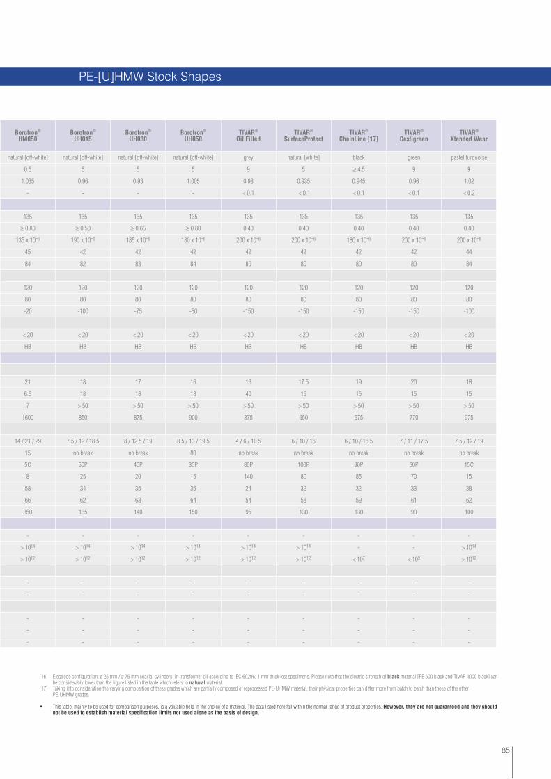
85
[16] Electrode confi guration: ø 25 mm / ø 75 mm coaxial cylinders; in transformer oil according to IEC 60296; 1 mm thick test specimens. Please note that the electric strength of black material [PE 500 black and TIVAR 1000 black] can be considerably lower than the fi gure listed in the table which refers to natural material. [17] Taking into consideration the varying composition of these grades which are partially composed of reprocessed PE-UHMW material, their physical properties can differ more from batch to batch than those of the other PE-UHMW grades.
• This table, mainly to be used for comparison purposes, is a valuable help in the choice of a material. The data listed here fall within the normal range of product properties. However, they are not guaranteed and they should not be used to establish material specifi cation limits nor used alone as the basis of design.
Borotron® HM050
Borotron® UH015
Borotron® UH030
Borotron® UH050
TIVAR® Oil Filled
TIVAR® SurfaceProtect
TIVAR® ChainLine [17]
TIVAR® Cestigreen
TIVAR® Xtended Wear
natural [off-white] natural [off-white] natural [off-white] natural [off-white] grey natural [white] black green pastel turquoise
0.5 5 5 5 9 5 ≥ 4.5 9 9
1.035 0.96 0.98 1.005 0.93 0.935 0.945 0.96 1.02
- - - - < 0.1 < 0.1 < 0.1 < 0.1 < 0.2
135 135 135 135 135 135 135 135 135
≥ 0.80 ≥ 0.50 ≥ 0.65 ≥ 0.80 0.40 0.40 0.40 0.40 0.40
135 x 10-6 190 x 10-6 185 x 10-6 180 x 10-6 200 x 10-6 200 x 10-6 180 x 10-6 200 x 10-6 200 x 10-6
45 42 42 42 42 42 42 42 44
84 82 83 84 80 80 80 80 84
120 120 120 120 120 120 120 120 120
80 80 80 80 80 80 80 80 80
-20 -100 -75 -50 -150 -150 -150 -150 -100
< 20 < 20 < 20 < 20 < 20 < 20 < 20 < 20 < 20
HB HB HB HB HB HB HB HB HB
21 18 17 16 16 17.5 19 20 18
6.5 18 18 18 40 15 15 15 15
7 > 50 > 50 > 50 > 50 > 50 > 50 > 50 > 50
1600 850 875 900 375 650 675 770 975
14 / 21 / 29 7.5 / 12 / 18.5 8 / 12.5 / 19 8.5 / 13 / 19.5 4 / 6 / 10.5 6 / 10 / 16 6 / 10 / 16.5 7 / 11 / 17.5 7.5 / 12 / 19
15 no break no break 80 no break no break no break no break no break
5C 50P 40P 30P 80P 100P 90P 60P 15C
8 25 20 15 140 80 85 70 15
58 34 35 36 24 32 32 33 38
66 62 63 64 54 58 59 61 62
350 135 140 150 95 130 130 90 100
- - - - - - - - -
> 1014 > 1014 > 1014 > 1014 > 1014 > 1014 - - > 1014
> 1012 > 1012 > 1012 > 1012 > 1012 > 1012 < 107 < 109 > 1012
- - - - - - - - -
- - - - - - - - -
- - - - - - - - -
- - - - - - - - -
- - - - - - - - -
PE-[U]HMW Stock Shapes

86
[1] Compression mouldingQuadrant engineering plastics are produced using state-of-the-art compression moulding technology. Polymer know-how and modern production technology are prerequisites for the functionality, quality and economics of Quadrant engineering materials. Compression moulded shapes are available in a broad variety of dimensions, thicknesses and diameters. For further information please refer to the Quadrant Delivery Programme.
[2] Ram-ExtrusionQuadrant provides engineering solutions by using ram-extrusion technology for the production of shapes, rods, tubes and profi les. This production technology offers special benefi ts:
No material wastage; rough rule of thumb: the material needed is less than the material taken away For sliding/guiding profi les this is the most economical production method as of approx. 1000 m per profi le [tool cost compensation] Highly complex geometries possible
Almost 100 different extrusion tools and more than 20 high technology extrusion machines guarantee fast availability of extruded products.
[3] Machining For more than 50 years we have been continuously developing and machining new high-performance plastic materials for cutting-edge applications. Our Technology Centres always put the needs of our customers fi rst. We co-design and machine from a drawing or start from a sample, and offer you a long term, stable and reliable fi nished component.
Quadrant machines ranges from small series to very big quantities, prototypes, high precision parts, complex geometries, small and large dimensions. We fulfi l industry specifi cations including special cleaning, marking, certifi cation, packaging and clean room technology based on samples, drawings or electronic fi les.
Our Core Machining Abilities & Technologies: Machine the most diffi cult materials Maintain superior fi nish and close tolerances Excellence in burr control Stress relieving capabilities Annealing knowledge Post curing techniques Surface treatments
Production Capabilities
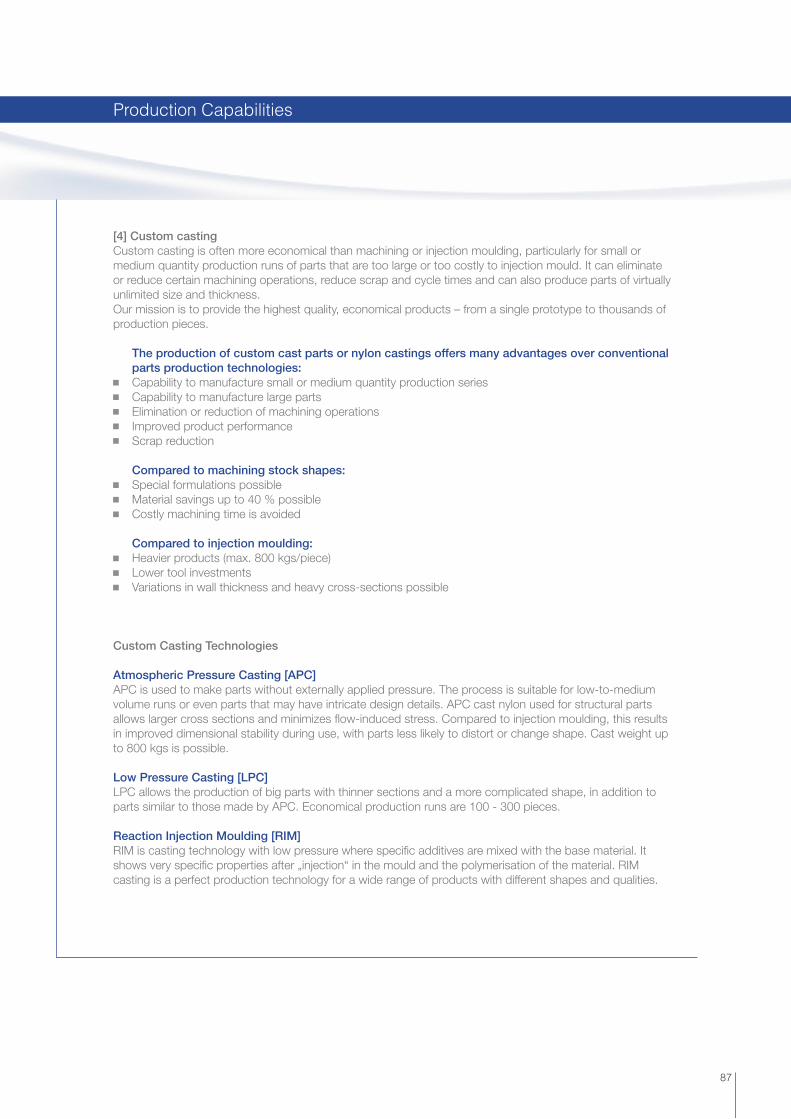
87
[4] Custom casting Custom casting is often more economical than machining or injection moulding, particularly for small or medium quantity production runs of parts that are too large or too costly to injection mould. It can eliminate or reduce certain machining operations, reduce scrap and cycle times and can also produce parts of virtually unlimited size and thickness.Our mission is to provide the highest quality, economical products – from a single prototype to thousands of production pieces.
The production of custom cast parts or nylon castings offers many advantages over conventional parts production technologies: Capability to manufacture small or medium quantity production series Capability to manufacture large parts Elimination or reduction of machining operations Improved product performance Scrap reduction
Compared to machining stock shapes: Special formulations possible Material savings up to 40 % possible Costly machining time is avoided
Compared to injection moulding: Heavier products (max. 800 kgs/piece) Lower tool investments Variations in wall thickness and heavy cross-sections possible
Custom Casting Technologies
Atmospheric Pressure Casting [APC]APC is used to make parts without externally applied pressure. The process is suitable for low-to-medium volume runs or even parts that may have intricate design details. APC cast nylon used for structural parts allows larger cross sections and minimizes fl ow-induced stress. Compared to injection moulding, this results in improved dimensional stability during use, with parts less likely to distort or change shape. Cast weight up to 800 kgs is possible.
Low Pressure Casting [LPC]LPC allows the production of big parts with thinner sections and a more complicated shape, in addition to parts similar to those made by APC. Economical production runs are 100 - 300 pieces.
Reaction Injection Moulding [RIM]RIM is casting technology with low pressure where specifi c additives are mixed with the base material. It shows very specifi c properties after „injection“ in the mould and the polymerisation of the material. RIM casting is a perfect production technology for a wide range of products with different shapes and qualities.
Production Capabilities

www.quadrantplastics.comQuadrant Engineering Plastic Products Worldwide
Quadrant EPP AG | Europe Hardstraße 5 CH-5600 Lenzburg T +41[0] 62 8858150 F +41[0] 62 [email protected]
Belgium | China | France | Germany | Hong Kong | Hungary | India | Italy | Japan | Korea | Mexico | Poland | South Africa | Switzerland The Netherlands | United Kingdom | United States of America
This brochure and any data and specifi cations presented here or on our website shall provide promotional and general information about the Engineering Plastic Products [the „Products“] manufactured and offered by Quadrant Engineering Plastic Products [„Quadrant“] and shall serve as a preliminary guide. All data and descriptions relating to the Products are of a general informational nature only. Neither this brochure nor any data and specifi cations presented on our website shall create or be implied to create any legal or contractual obligation. This brochure and any data or specifi cations herein do not create expressly or by implication any legal, contractual or warranty obligation whatsoever. No warranty of any kind, either express or implied, is made as to the information contained in these pages, including, but not limited to, all warranties provided for by Louisiana law, any implied warranty of merchantability, of fi tness for a particular purpose, and any warranty against hidden defects or redhibitory defects or vices. No information in this brochure creates any express or implied warranty that the goods described herein shall conform to any description herein. Quadrant sells the products described herein solely to sophisticated users and not to consumers, and Quadrant assumes no responsibility that any goods described herein will be fi t for any particular purpose for which a Quadrant customer may determine to purchase such goods, except and to the sole extent otherwise provided in a separate written contract.Any illustration of the possible fi elds of application of the Products shall merely demonstrate the potential of these Products, but any such description does not constitute any kind of covenant or warranty whatsoever. Irrespective of any tests that Quadrant may have carried out with respect to any Product, Quadrant does not possess expertise in evaluating the suitability of its ma-terials or Products for use in specifi c applications or products manufactured or offered by the customer respectively. It thus remains the customer‘s sole responsibility to test and assess the suitability and compatibility of Quadrant‘s Products for its intended applications, processes and uses, and to choose those Products that according to its assessment meet the requirements applicable to the specifi c use of the fi nished product. The customer undertakes all liability in respect of the application, processing or use of the aforementioned information or product, or any consequence thereof, and shall verify its quality and other properties.Quadrant‘s Products should not be used for applications involving medical devices that are intended to remain implanted in the human body continuously for a period exceeding 24 hours [30 days*], or are intended to remain in contact with internal human tissue or bodily fl uids for more than 24 hours (30 days*), or as critical components of medical devices that are essential to the continuation of human life.
*: „30 days“ applies to Ketron® CLASSIXTM LSG PEEK white only.
Quadrant is not a medical device manufacturer and the information herein does not constitute any express or implied warranties or representations whatsoever, including, but not limited to, all warranties provided for by Louisiana law, any implied warranty of merchantability, of fi tness for a particular purpose, any warranty against hidden defects or redhibitory defects or vices, or that Quadrant’s materials are manufactured in accordance with the quality standards appropriate and necessary for materials intended for use in implantable medical device applications and in applications that are essential to the restoration of or continuation of a bodily function important to the continuation of human life.
Acetron®, Borotron®, Duratron®, Ertacetal®, Ertalon®, Ertalyte®, Fluorosint®, Ketron®, Nylatron®, Quadrant®, Semitron®, Symalit®, Techtron® and TIVAR® are registered trademarks of the Quadrant Group. CLASSIXTM PEEK is a trademark of Invibio Ltd.DELRIN® is a registered trademark of DuPont.
This guide was created by Quadrant Engineering Plastic Products. Design and content are protected by copyright law. Copyright© 2011 The Quadrant group of companies. All rights reserved.
Quadrant EPP USA, Inc. | North America2120 Fairmont AvenuePO Box 14235 - Reading, PA 19612-4235T 800 366 0300 | +1 610 320 6600F 800 366 0301 | +1 610 320 [email protected]
Quadrant EPP Asia Pacifi c Ltd | Asia-Pacifi c60 Ha Mei San Tsuen, Ping ShanYuen Long - NT Hong KongT +852 24702683F +852 [email protected]
Lit_
Pro
dCat
_QE
PP
_12/
11