digitool.library.mcgill.cadigitool.library.mcgill.ca/thesisfile61258.pdf · · 2009-11-02the...
TRANSCRIPT

.---i
------ --
A TEMPEHATURE C('~JTROL STRATEGY FOR
STELCO McMASTER WORKS
by
Angelo M. Grandillo
A 'rhesis Submitted to the E'aculty of Graduate Studies and ReSearch in Partial Fulfillment of the Requirements
for the Degree of Master of Engineering
Department of Mining and Metallurgical Engineering Mc Gill Uni ver s i t Y Montreal, Canada
JANUARY 1988

t'
AC KNOW LED GEME NTS
1 wish to extend my sincere gratitude to Professor
F. Mucciardi, supervisor of this work and valued friend, for aIl
his efforts and help. l also wish to acknowledge the financial
contribution made by NSERC by way of an Industrial Postgraduate
Scholarship and the support recieved from management and
employees of Stelco, McMaster Works. Finally, l wish to thank
my mother for having given up her upstairs k i tchen table for the
past two years and having put up with me.
1

T A BLE o F CONTENTS
P':HJt'
Abstract.......... ..........•.......................... v Resume .••••••.••••..••••..••••.••••••••.••...••••.••••. Vil
List of Figures...................................... ... x Lis t 0 f Ta b 1 es. • • • . . • • • • . . • • • • . • . • • • • . . • • • • . . . • • • . • • • •• X '1 i
CHAPTER 1:
CHAPTER 2:
CHAPTER 3:
1.1
1.2
2.1
In trad u ct ion. . ......................•..
Ste1co McMa s ter Wor ks Steelmak i ng Facilities -Overview .•••••...•••.•.••..
Scope of Present Work •••••••.•••••••••.
The Continuous Casting Process ••••••••.
History of Continuous Casting ........ ..
L
l
4
7
9
2.2 Components of a Continuous Casting Machine •••••••••••••••••••• ., •• ~ •••••••• 15
2.2.1 The Tunùish ••....••.....•...........•.. 15 2.2.2 Tlle Mauld ..••....••....•••...•••...••.. 20 2.2.3 The Spray Zone......................... 24
2.3 Operating Aspects of Continuous Castillg .....•..... o ••••••••••••••• 2B
solidification and Structure of Con tin U 0 U S 1 y Ca s t Ste el B i 11 e t s • .. • • • • • 3 1
3.1 The Ct1ill Zone ..•••••...•••. , ••....••.. 33
3.2 InternaI Structure of Continuously Cast BIllets........................... 37
3.2.1 Mechanica1 Propertles of Steel at High Temperature....................... 37
3.2.2 Axial Segregation and "Mini-lngot" Formation •••••••••••••••••••••••••••••• 39
1 l

CHAPT ER 4:
CHAPT ER 5:
CHAPTER 6:
3.3 VarIables Influencing Cast Structure... 43
3.3.1 Machine DesIgn ....•.•..•.•..•••••...••• 45 3.3.2 Influence of SectIon Slze .••••.•....••• 46 3.3.3 Effect of Steel Composition ••••••••.••• 48 3.3.4 Influence of Castlng Temperature and
Flow Conditions in the Liquid Pool ••••• 50
Controlling Steel Temperature in the Ladle.............................. 59
4.1 Theoretical Simulations of Thermal Cycling of Ladies ••.••••••••••••••••••• 74
4.1.1 Procedure •••••••••••••••••••••••••••••• 75 4.1.2 Discussion and Results ••••••••••••••••• 79
4.2 Ladle Refining Furnaces ................ 104
Contro11ing Steel Temperature in the Tu nd i s h •••..... lit • • • • • • • • • • • • • • • • • •• 110
5.1 Flow Control Deviees ••••••••••••••••••• 112
5.2 Heating Steel in the Tundish Dur 1 ng Cast i ng ••.••..•.••...••..•..•••. 118
5.3 Scrap Additions to the Tundish to Reduce Superheat ..•••••••••••••••••. 127
5.3.1 Thermal and Klnet1c Conslderations ••••• 128 5.3.2 Plant Trials Conducted at
McMaster Works •.••••..••••••••••••••••• 133
Controll1ng Steel Temperature ln the Mould ...••....•.................••. 148
6.1 previous Work ••••••.••••••••••••••••••• 149
6.1.1 Work From USSR •.••••••••••••••••••••••• 151 6.1.2 Work From Ita1y •••••••••••••••••••••••• 155
6.2 Trial Work Performed at McMaster Works ..••••••••••••••••••••••• 159
6.2.1 Preparatory Stage •..•.••••••••.•••••••• 159 6.2.2 Experimental Stage ••••••••••••••••••••• 168
l l l

-i CHAPTER 7: Summary and Conclusions •••••••••••••••• 174
Appendix 1 ............................................. . 181
References ..•.•.••.•.•...••••..•••.•...............•...
lV

..
l\.BSTRACT
In thlS stuày, it was shown that Improvements in
the quality of continuously cast steel billets, similar to those
which can be achieved by e1ectromagnetic stirring (EMS) of the
liquid pool durlng solidifIcation, can be obtained if casting
superhe~ts can be consistently controlled at low levels. A
lack of casting temperature control is not only detrimentai ta
the quality of the cast prùduct, but also ta a shop's overall
productlvity. The important variables for temperature control
in the ladle, tundish and mould were quantified and possIble
methods of controlling these variables were proposed.
The thermal state of the ladle lining is one of
tbp major contributors ta the variabllity ln casting
temperature. This was shawn by performlng theoretical ladle
cycle slmulatlons of the Stelco McMaster Works 80 tonne ladIes
using a general heat and mass transfer computer software package
developed at McGill University, known as FASTP (Facility for the
Ana 1 ys ISO f Sys tem::; in Tr anspor t Phenomena). It was shown tha t
by reducing energy losses from the refractory ladie 1ining, by
way of Incorporatlng an Insulating refractory tile between the
ladle sheli and the safety linlng and by using a ladle lid
throughout the cycle of the lad le, te~perature lasses from the
liquid steel can be substantlally decreased. This can translate
lnto a decrease of heat ta heat temperature variabi1ity and the
v

1
..
....
model predicts that electric arc furnace tap temperatLlres can bl'
decreased by about 33 oC. Thus a significant improvement in
furnace prod uct i vi ty can be ach i eved •
Since, from an operating point of view, it is
preferable to cast steel on the hot side, it was determined in
th i s study that fu r ther temper a ture contro 1 can be ach i eved by
scrap cooling in the tundish. A theoretical kinetic analysis of
the McMaster Works tundish was performed, again using FJ\STP, and
it was determined that sufficient turbulence exists in the
tundish pourbox to melt scrap, l02mm X l02mm billet crops, or
sma11er bar mill crops, in order to further decrease superheat
and at the same time use excess energy which would have
otherwise been wasted to increase production. Trial heats
performed at McMaster Works showed that scrap additions to the
tundish are feasible and serve their purpose.
Liquid steel entering the mould always requires d
minimum of about lS oC superheat in arder for it to have
sufficient f1uidity to transfer from the tundish to the mould.
In order to help dissipate this superleat more quickly, this
study investlgated the feasibillty of feeding a high purity iron
powder into the mould during casting. Additions in the order of
1% were made and results supported work performed by other
researchers. Significant improvements in internal quality of
the cast product were observed •
VI

1 Darl'-, cetle étude, il (" .. ,t démontr<? p01Jr des billettes
pr()dlli tes par co',16e contin ;l', qlle des améliorations semblables
(\ Cl' 1 h·s r6alic;écs par bra~sage r-lectromagnétiqlle du liquide
en ~olidification peuvent être obten\les, si la slJrChallffe de
l'acit'r liquide' est contrôlée a bas niveau. Un manque de
contrôle dl' la température de Caillée affecte non seulement
la q11alité d" prOÙllit mais allssi la prodl1ctivité globale d'une
aciérie. Les variables importantes pOlIr le contrôle de la
tempéra turc: dans la poche de cO\ll~e, le panier réparti teur
L't le mOllle ont été quantifiées et des méthodes pour contrôler
ces variab les on t été proposées.
<1 La variabi lité de la tempéra ture de coulée es t dû en
"" majellre partie à l'état thermique de la brique réfractaire
dans la poche de co: lée. Cee i a é té démon tré par des
simulations théoriqlles basées sur les poches de 80 tonnes
de l'usine McHaster de la compagnie Stelco. Les sinlulations
on tété e ffec r-u6e s à l'aide dll logic ie l FAS TP (Faci li ty for
the Analysis of Systems in Transport Phenornena) développé
à l'l'niversiré }1cGill pOlir la simulation de transfert de
chaleur et de masse. Les résultats ont démontré que les
pertes de tempéra ture de l'acier liquide pe\lvent être
rédllites en diminuant les pertes thermiques du réfractaire
de poche à l'aide d'une tuile isolante entre la coquille
V 1 l

-
1
----------~-~---
de la poche et le revêtement de' sécurilé. et d'un cOllvl'rch'"
posé sur la poche pendant le cyclL'. Il en n~sllltl' \me
ba is se de la va riab il i té de la tcmp0ra turc, dl' cOlllée L'Il
coulée. Les calculs théoriques prvdisent que la tcmp(>raturc
de vidange pOlir un four à arc plectriquc peut ~tre réduill'
d'environ 33°c. La conclusion révèle donc une augmentatioll
de la producti vi té du four à arc.
Puisque du point de vue opérationnel il est préférable
de couler l'acier à des températures plutôt chaudes, l'ptllde
a révélé que dans le contrôle de la température de coul('c,
des gains additionnels peuvent être obtenus par l'addition
de ferraille dans le panier répartiteur, pour refroidir
l'acier liquide. Une ana lyse théorique des paniers
répartiteurs de l'usine Nct-1aster fOt réalisé avec le
logiciel FASTP. Les résultats ont démontré qu'il exis te
suffisanunent de turbulence dans le panier répartiteur
pour fondre des morceaux de bi Ile t tes de 102 rrnn x 102 mm
ou des morceaux de barres provenant du laminoir. Cette
technique perme t de réduire la tempÉ'ra turc de surchau f f(>
en utilisant l'énergie excédentaire qui autrement aurait
été perdue. Des expériences rÂalisées à l'usine McMaster
ont révélé que l'addition de ferraille dans le panier
répartiteur est faisable.
Vl11
1
L'acil'r liqlIide sortant dt! panier répartiteur nécessite
'Inl' <""lrcha1!ffp minimum de lS"C pOlIr maintenir lme fluidité
'-il!ffisanLe pOlIr passer dlI panier au moule. Pour aider à
dis<.,ipcr cettt' slJrchauffe pJus rapidement, une étude de
[ai~ahiliU~ a évaluer la possihilité d'ajouter une poudre
de ft' r plJr dans le mOllie dl Iran t la c01l1ée. Des additions
de l'ordre dt' 1010 ont ét0 faites pendant la coulée continue.
Ll'S résultats confirment le travail d'autres chercheurs et des
améliorations considérables de la qualité interne des billettes
ont été ob'-iervées.
lX

•
..
LIST OF FIGURES (reE) -----------------------
Figure 1.1: Fishbone diagram of variables afEecting quality and productivity.
Figure 2.1: Basic elements of a continuous casting machine. (4)
Figure 2.2: Diagram of Bessemer process [or continuous casting. (5)
Figure 2.3: Four basic caster designs. (4)
Figure 2.4: Wor1dwide production of crude steel and share of continuous casting. (7)
Figure 2.5: Continuous casting billet machines in operation. (7)
Figure 2.6: Bloom machines / Strands in operation. (7)
Figure 2.7: Slab machines 1 Strands in operation. (7)
Figure 2.8: Relation between mean number of inclusions (>100 microns) in slabs and flow control. (8)
Figure 2.9: Distribution of metallurgical Eunctions between furnace, ladle and tundish. (17.1)
Figure 2.10: Transverse section of (a) billet and (h) slab showing formation of air gap. (18.2)
Figure 2.11: Billet defects. (18.3)
Figure 3.1: InternaI structure of continuously cast steel billets.
Figure 3.2: Transverse cut of AISI Grade 5160 H (low casting superheat) •
x

Figure 3.3:
Figure 3.4:
Figure 3.5:
Figure 3.6:
Figure 3.7:
Figure 3.8:
Figure 3.9:
Trandverse cut of AISI Grade 5160 H (high casting sl.lperheat) •
% Equiaxed vs. Index of Center Segregation for several shapes and sizes. (25.1)
Mini-in90ts formation model. (24)
Core segregation in high-carbon spring wire resulting in breakage during drawing operation.
Quarter point inclusions.
Relation between segregation index of C and segregation index of P, S, Mn. (26)
Morpho10gy of solid/liquid interface as a function of temperature grad ient (G), rate of solidifica ... ion (R) and undercooling (AT). (2J)
Figure 3.10: Histogram of center segregation ratio of C for various casting conditions. (26)
Flgure 3.11: Effect of steel superheat on the relative size of the equiaxed zone with and without EMS. (From IRSID)
Figure 3.12: Effect of casting temperature on the size of the equiaxed zone and on the severity of axial segregation. (27)
Figure 4.1: Distribution of average steel temperature in the tundish for AISI Grade 5160 H.
Figure 4.2: Distribution of steel temperature 1055 between the ladle and the tundish for AISI Gr~de 5160 H.
Figure 4.3: Distribution of first steel temperature measured in the ladle for AISI Grade 5160 H.
Figure 4.4: Regression analysis of ladle vs. tundish temperature.
><1

Figure 4.5:
Figure 4.6:
Figure 4.7:
Figure 4.8:
Figure 4.9:
Figure 4.10:
Effect of argon bubbling in the ladle on steel temperature profile in the tundish. (32)
Diagram of energy flow in the ladle for steel casting. (33)
The effect of different refractory types on the ladle cooling behavior with a preheat of 400 0 C and a furnace tap temperature of 1650 oC. (33)
Lining configuration and thermal properties used in the simulation. l-Regular Lining 2-Insulated Li n i ng.
Simulated ladle cycle.
Energy balance equating temperature lost by liquid steel to energy gained by lining and energy lost to the surroundings.
Figure 4.11: predicted progression of cold-face temperature rise for regular and insulated ladIes during preheating of newly lined ladIes.
Figure 4.12: predicted progression of hot-face temperature rise for regular and insulated ladIes during preheating of newly lined ladIes.
Figure 4.13: Energy distribution after preheating of newly lined ladIes.
Figure 4.14: Increase in lining energy content during the first 5 heats on a regular ladle. (liquid steel/lining contact time = 130 minutes)
Figure 4.15: Increase in lining energy content during the first 5 heats on an insulated ladle. (liquid steel/lining contact time = 130 minutes)
Figure 4.16: Comparison of energy content of regular and insulated linings after working temperature has been reached, as a function of contact time t.
Xl l

Figure 4.17: Temperature profile through a regular lining at the end of each step in a cycle after the ladle has reached working temperature.
Figure 4.18:
Figure 4.19:
Figure 4.20:
Figure 4.21:
Figure 4.22:
Temperature profile through an insulated lining at the end of each step in a cycle after the ladle has reached working temperature.
simulation results of equivalent liquid steel temperature loss (oC) for a regular ladle versus 5n insulated ladle.
simulation results of equivalent liquid steel temperature loss (oC) for an insulated ladle having a captive lido
Final manganese distribution for LF practice at U.S. Steel, Fairfield Works.
Final Carbon distribution for LF practice at U.S. Steel, Fairfield Works.
Figure 4.23: Within-heat temperature 1055 distribution in the tundish with LF practice at U.S. Steel, Fairfield Works.
Figure 5.1:
Figure 5.2:
Figure 5.3:
Figure 5.4:
Figure 5.5:
Example of a typical temperature profile in the McMaster Works Tundish.
McMaster Works tundish.
Fuil-scale water model of the McMaster Works tundish.
Flow patterns in a tundish with no flow control devices incorporated.
Flow patterns in a tundish with optimum flow control configuration.
Xlll

Figure 5.6: Schematic of heating system for molten steel in the tundish during continuous casting. (42)
Figure 5.7: Temperature variations of steel in the tundish for conventional casting practice. (42)
Figure 5.8: Temperature variations of steel in the tundish for experimental heats using the heating system. (42)
Figure 5.9: Effect of using the heating system on first and last slab reject frequency. (42)
Figure 5.10: Enthalpy balance for determining amount of scrap addition required to drop liquid steel superheat by the desired amount.
Figure 5.11: Oimensionless relationship for melting kinetics of steel cylinders immersed into liquid steel at 1570 0 C. Bath liquid steel and cylinders are assumed to have a liquidus temperature of l53S oC and a solidus temperature of 1490 oC.
Figure 5.12: Regression analysis for determining the relationship between Bi and Fo fOl total time required ta completely melt the cylinders.
Figure 5.13: Test cylinder after a 5 second immersion.
Figure 5.14: Experimental data points as they appear on the diroensionless relationship established in Figure 5.11.
Figure 5.15: Tundish temperature profile for trial heat #23875.
Figure 5.16: Tundish temperature profile for trial heat #23982.
Figure 5.17: Tundish temperature profile for trial heat #24329.
Figure 6.1: Sample 23-Transverse section, no iron powder (46) Sample 24-Longitudinal section, no iron powder Sample 25-Transverse section, with iron powder Sample 26-Longitudinal section, with iron powder
XlV

Figure 6.2:
Figure 6.3:
Figure 6.4:
Figure 6.5:
Figure 6.6:
Figure 6.7:
Figure 6.8:
Iron powder addition method using a carrier gas. (46 )
Schematic drawing of metal powder feeding apparatus. (49)
Schema tic of powder feeding system developed for trials at McMaster Works.
Heat #33241 control billet sample macro-etch.
Heat #33241 trial billet sample macro-etch.
Heat #33291 control billet sample macro-etch.
Heat #33291 trial billet sample macro-etch.
xv

-
Table 1.1:
Table 1.2:
Table 3.1:
Table 3.2:
Table 4.1:
Table 4.2:
Table 4.3:
Table 4.4:
Table 5.1:
Table 5.2:
Table 5.3:
LIS T 0 F T A BLE S
McMaster Works electric arc furnace characteristics.
McMaster Works caster characteristics.
Effect of carbon content on various aspects of solidification and cast structure.
Chemical composition and casting conditions of test billets.
Implications associated with the lack of control of liquid steel superheat in the tundish when using metering nozzles as a means of steel (low control.
Parameter table and ANOVA table for regression analysis.
EAF temperature compensation required for heats prior to attaining working temperature of the lining.
Comparison of maximum sheli temperature (oC) for regular and insulated ladIes; predicted results and actual plant data.
Results of water model analysis showing retention time and volume fraction comparisons for tundish without flow control devices versus tundish with optimum flow control configuration.
Composition of test cylinders, liquid steel and bath conditions.
Results of cylinder immersion tests used for determination of h. (d(initial)=23.9mm)
XVl

Table 5.4:
Table 6.1:
Table 6.2:
Table 6.3:
Condition of trial heats for scrap additions in the tundish.
Increase in billet production cost ($ per tonne) as a function of amount of powder added (shown in weight %) and price of iron powder.
properties of ATOMET 28 and ATOMET 602 iron powders (as per QMP catalogue) •
Chemistry and casting parameters for iron powder addition trial heats.
XV 11
l

1
PM
CHA PTE R 1
Introducllon
1.1 Stelco McMaster Works Steelmaking Facilities Overview
The work presented in this thesis was carried out
at Stelco McMaster Works, Steelmaking Department. McMaster
Works is located in Contrecoeur, Quebec; about 40 km north-east
of Montreal. Steelmaking facilities were commissioned in 1974 by
the consulting firm Hatch Associates. Originally deslgned for n
nominal capacity of 175,000 tonnes per year (100% merchant
quality) , continuous improvements to procedures and equipment,
allowed production to top 300,000 tonnes ln 1985, of which, 80%
was special bar quality (SBQ) mainly for the automotive
inèustry.
The present installation consists of an electrlc
arc furnace and a 4-strand billet caster. The furnace melt
capacity is 80 tonnes. Power is delivered by a three phase
transformer of 50 MVA capacity. Three oxy-fuel burners rated at
4.5 MW each are also used during melting. This combination
gives an average tap-to-tap time of 120 minutes (including
maintenance and breakdown delays). Table 1.1 shows sorne
characteristics of the furnace.

When a heat has reached the required temperature
t and carbon level in the furnace, it is tapped into a pre-heated,
dolomite lined ladle where carbon and ferro-alloys are added as
necessary. Ladle treatment of the steel consists of argon or
nitrogen stirring through a porous plug and if required,
elements such as silicon, manganese and carbon can be injected
in the form of a cored wire.
The heat is then delivered to the continuous
casting department. The casting machine, de1ivered by
'Concast', is of the curved type with a radius of 7.92 m. From
the ladle, steel is teemed into a tundish of Il.0 tonne
capacity. From the tundish, steel is distributed to 4 strands.
Table 1.2 gives sorne characteristics of the casting machine.
~bout one-third of the steel produced at McMaster
Works is AISI GRADE 5160 used in the fabrication of spring flats
for the automotive industry. The rernaining two-thirds of the
production has a variety of other applications ranging from
rounds for automotive forgings to wire for nail production, to
reinforcing bars.
2

Table 1.1: McMaster Works E1ectric ~rc Futnil~e Characteristics
1. She11 Diameter (m)
2. Transformer Capacity (MVA)
3. Maximum Power Input (MW) rncluding Oxy-Fuel Burners
4. TOp or Door Charged
5. Electrode Size (mm)
6. Shell and roof
7. product Mix: % Heats - Carbon % Heats - Alloy
Table 1.2: McMaster Works Caster Characteristics
Il. Manufacturer
Type 2.
3 • Curve radius (m)
4 • Number of strands
5. sequence Casting
16
• Tundish Capacity ( tonnes)
7. Sizes of Squares Cast (mm)
8. Mou1d length (mm)
9. Spray Zone Length (m)
10. Typica1 Casting speeds (m/m i n) 89 mm
102 mm 152 mm
----------~-_ .... _.- --
3
50
40 53.5
top
508
water-coo1ed
65 35
CONCAST
Curved
7.92
4
Yes
11.0
89, 102,
813
1.5
3.3 2.8 1.3
152

1.2 Scope of Present Work
For any continuous casting operation to be
competitive in today's markets it must be able to meet the
meticulous quality demands imposed by customers while keeping
production costs down. It used to be that quality and
productivity were thought to be two counteracting forces and one
could only be achieved at the expense of the other. In today's
environment, steelmakers are beginning to reject this
philosophy. They now realize that quality and productivity
really mean the same thing and one can't be obtained without the
other. By adopting concepts such as "Statistical Process
Control", steelmakers realize that in order to consistently
obtain high quality, procebses must operate in statistical
control. 1 ,2,3
~s can be seen in Figure 1.1, the three main
parameters characterizing the condition of steel during
steelmaking are temperature, composition, and fluid flow. The
extent to which these three parameters can be controlled wi:l
ultimately deterrnjne the consistency of the response parametersi
namely quality and productivity.
4

Ul
-
TEMPERATURE FLUID FLOW
COlvlPOSITION
Fl.gure 1.1: Fl.shbone dl.agrarn of varlables affectlng qua1ity and productl.vl.ty.
QUALITY PRODUCTIVITY

The focus of the work presented in the chapters to
follow will be on steel temperature and flow in the liquid pool
of the solidifying strand. The main objectives of the work can
be summarized as follows:
1) to presen t a comprehens ive litera ture rev iew in
order to show how the quality of continuously cast
billets is affected by steel superheat and other
operating variables. This will, whenever possible, be
supported by actual plant data from McMaster Works.
2) to show, by means 0 f a compu ter s irnula t ion of the
thermal cycles of McMaster Works ladles, what action
can be taken to reduce overall temperature variability,
hence reduce tap temperatures in the EAF.
3) to present viable methods of further reducing
temperature variability in the tundish during
continuous casting.
4) to discuss and present results of plant trials
performed in order to determine the effects of adàing a
high purity iron powder to the mould during continuous
casting as a means of providing supplemental cooling to
the liquid pool of the solidifying strand.
6

•
CHA PTE R 2
The Continuous Casting Process
The development of continuous casting provides the
stee1maker with an economically attractive alternative ta
conventiona1 ingot casting. Since the end product of the
continuous casting operation i5 a 5emi-fini5hed shape, the cost
intensive prirnary r011ing stage required for in00t processing i5
e1iminated. Improvement5 in yield, surface and internaI qu~lity
are among sorne of the advantages continuous casting offers over
ingot casting.
Figure 2.1 shows the basic e1ernents of a
continuous casting machine. Steel supplied from the melt shop
via a lad1e, i5 teem0d into a tundish which in turn feeds one or
several water-cooled copper moulds. As the solidifying strand
exits the mould it enters a spray cooling zone. The cast
section is then cut to 1ength thus giving a semi-finished
product ready for subsequent processing.
In this chapter a brief history of the development
of continuous casting will be given and the basic components of
the casting machine and the casting process will be described.
7

OJ
l - Ladle 2 - TundJ.sh 3 - Mould 4 - Spray Cool~ng zone 5 - Stralghtener 6 - Cuttlng Torches 7 - Electro-Magnetic Stirring
~ ... w .... ~ ... w
::.::.:.~ :.~':":::':.::"::}f.'::::'::~::~:-:;':::'~.{~;':~';':~;'$;':~;:i:;':5;C''':~;':~:?5:t:f'::';':)i:,};:.JJ}J IJ.~~Ht~.:~:: !-,,'.;. '-': .:~ •. ~:-••• ;' ••• '.' '.' .....: .. :
Figure 2.1: Basic e1ements of a continuous casting machine. (4)
." l 1

•
j 2.1 History of Continuous Casting
Continuous casting of metals has a history going
bac\{ to before 1840 when a patent was granted to George Sellers
who developed a machine for continuously casting lead pipe. 5
Sir Henry Bessemer patented his idea of continuous casting of
steel plates in 1846 and ran plant trials in the 1890' s.
Figure 2.2 shows a diagram of the Bessemer process.
The first commercial casting machine was developed
for continuous casting of brass billets in the early 1930'5 by
s. Junghans in Germany. He also introduced the oscillating
mould system des igned for the purpose of avo id i ng st i ck ing 0 f
the casting to the mould.
In the 1930's Al1egheny-Ludlum began development
of a continuous casting machine for steel using Junghans'
oscillating mould. It wasn't until the early 1950'5 though that
Allegheny-Ludlum and others were successful on a pi lot plant
scale. By 1960, there were two commercial production machines
in operation. It' s only been in the past 15 years that
cont i nuous cast i ng of steel has und erg one i ts mos t rap id 9 rowth.
The development of mater ials and processes and the advent of
automation and computer control has given continuous casting
significant advantages over conventional ingot casting; namely
superior quality, higher yield and higher production rates. The
9

r
.,.,.,A' ROLLS
/ ';,. éf~
~ o
. , , '~\I '~
SOL.IU ME1AL--'
1 . Il' , r'f'l '
cJ~
\ o
WATE" SPRAYS
Figure 2.2: Diagram of Bessemer process for continuous casting. (5)
t 0

• l
overall reduction in steel production costs associated with
continuous casting, when compared ta ingot casting, makes it
extremely difficult for ingot casting operations to remain
viable in the near future.
Figure 2.3 shows the four basic caster designs.
The first machines built were of the vertical type. Curved
machines were then developed to minimize the height of
installations and to allow existing plants to incorporate
continuous casting without having to modify crane height. This
trend to cornpactness and reduction in height is today being
taken to an extreme with the develaprnent of horizontal
con t i nuous cast i ng. 6
Figure 2.4 shows how continuous casting has grown
over the years. More than 40% of today' s total steel production
is continuously cast. Figures 2.5 to 2.7 show how drarnatically
the number of casting machines has increased in recent years.
1 t

-~ ct 20 .... .... ct :;; 15 z LI.
o la lx g 5 ::t:
Il
Il
$$-$$-
-.-, $ $- Il
l}~ 4-1/ $Il ;.
;/' ~-$ O~~ ____ ~~~_~~ __ ~ __ __
VERTICAL ST. w /BENDING CURVED
Figure 2.3: Four basic caster designs. (4)
\2
BOWED

•
1.000 :E: 900 WORLD StEEL PROIJUCliOIi :::> ~ 800 Z WOAlD CII\JOf IIlIl PMX>UCI"'" c:( ,
700 \ , , 0::: w
600 .-' a.. (%) ./ t/) 500 z
SIIARE ΠCC-PRODUCtiON ..-liilRLn C~-:= qOO 1ii'0' DI' ec--..cllON 1%1 ,," PROUUC 1 ON z
\ /" ~D C('POOOUCIION 0 300 "" , ...J 200 .,.~ ..... ' 1 ..-'-...J .......... 1 _._ ...... -:E: 100 .' .J~ • .,. .... -
._----.::----_ .. --------0 ........ -.- --_ ... '65 '70 ']'; '80 '85
(ALE~DfIR )fAR CONCAST UNION A.G. WORLD (ASTER S RVEY 198Q.1.
WORLDWIDE PRODUCllON or (RUVE SJEI:l AND FIGuP~ 2.4
1800
~1600 z: ~ 1QOO l-V) 1200 ."
1/) 1000 UJ z: ;: 800 u ~ 600
~ ~OO
~ 200 z:
o
",.ettlMfS
".AHDS
rrfufu if "f
SUARE OF CONTINUOUS CASTING (7)
--f- f- f- t-
- -- - - - -r- t- I- :--- - - -
f- - - - - - - - -
1-- - - - r- f- - - -- r-
t- - f-
1 r if " ,
1 ,
1968 69 70 71 72 73 7Q 75 76 77 78 79 80 81 82 83 814 YEAR
CONCAST SERVICE UNION A,G •• WORLD CASIER SURVEY 198~-1
'IC:C~r: 2.5 COtHIHUOUS CASlIHG BillET MACHINEs
IN OPERATION (7)
13
50 q5 qO :55 1-:50 z
lLJ
25 u ~ UJ D-
20 J5 10 5 0
1
2

900
BOO
700 -r-en c:J z: 600 --t--r-CI; 0:: ~
1- t- :- r-Vl 500 0lil
Vl UJ
400 - 1- t- r- t- r- f--z: - 300 ::r: f- f- i- - 1- -l-L) M'CHINtl
~ ""AHol
200 1- !- 1- - r-~
n If ~ ..; 100 t- c- t- 1 II ~ rf
- r-0
1 fJ 1 r r r r z:: 0 1968 69 70 71 72 73 14 75 76 77 78 79 80 81 82 83 84
YEAR CONCAST SERVICE 11H10 A.G WORI D CASTERSlIRYllIQR4-1
BLOOH t\ACHtNES 1 ST RANDS IK OPERM ION 3 fo'ICùRL' 2.6 (7)
450
Vl 400 Cl
~ 350 0::
t;; 300 0lil 250 Vl
~ 200 ::r: "ltHlH(~ '-' 150 "1 '''IAHOS
r t-~ ~
100 ~ 1 fl . 50 r r ..., ri 1111111 1 0 z:: 0
1968 69 70 71 72 73 74 75 76 71 78 79 80 81 82 83 84 YEAR
COHCAST SERVICE UNiOn. WORlD CASTER SURVEY. 1984-1.
SLAB MACHINES 1 ST RANDS IN OPERATION ~ICCRL 2.7
( 7) q
\4

2.2 Components of a Continuous Casting Machine
Casting machines may differ in size, capacity,
shape, sizes and shapes of sections cast, number of strands and
other design characteristics but they aIl have the following
components which serve a common purpose.
2.2.1 The Tund i sh
In a continuous casting operation the primary
function of the tundish is to distribute a controlled amount of
mol ten steel from the ladle to the mould or moulds. 8 The
tundish is also counted upon to perform a variety of other
functions which are now summarized.
1) Casting Speed Control
Casting speed i5 determined by the rate at which
steel is supplied from the tundish to the moulds. In practice
this is done in one of two ways. The traditional method makes
use of metering nozzles and steel level in the tundish to
control speed. Thus this method is based on operating with a
constant nazzle aperture and varying the steel level to yield
the required steel supply ta the moulds. This method is
preferred due to the relatively low costs in both nozzle
installation and maintenance when compared to other available
15

methods. The major disadvantages of this system are in its
ineffectiveness for accurate speed control due to the long
response time of the system and the high risk of slag
entrainment caused by vortexing, especial1y when casting at
lower speeds (i. e. lower tund ish levels) •
The more modern casters are equipped with
slidegates, stopper rods or sometimes both. A1though these
systems are much more expensive to instal1 and maintain, they
allow a full tundish level to be malntained throughout a cast.
Casting speed can be changed instantaneous1y by changing the
effective nozz1e aperture.
2) Buffer for Sequence Casting
Sequence casting (i.e. casting heats one after
another wi thout interrupti ng the steel supp1y to the mou1ds) is
essential in order to reduce production costs and improve steel
quality. Production cost reductions are achieved by the
resu1ting increase in billet yield, saving on tundish board
refractory by having more than one heat cast in the same tundish
and a reduction in operating personnel since less tundishes have
to be prepared and less caster set-ups are required. Qua1ity is
improved because the casting machine is allowed to run at
"steady-state" for longer periods of time.
16

3) Removal of Non-Metallic Inclusion
Much work has been done and is being done on
optimizing tundish design i.e. size, shape, etc. and
incorporating flow control devices aimed at increasing sleel
residence time in the tundish 50 as to enhance inclusion
flotation. 8 ,9,lO,11 A good example of the results which can be
achieved by flow control devices is seen in Figure 2.8.
4) Chemistry and Inclusion Shape Control
Traditionally steel chemistry control has been
achieved by alloy additions (trimming) and inclusion shape
control by additions of rare earths or calcium in the ladle (ie:
ladle metallurgy) .12,13,14 The developers of ladle metallurgy
technology have extended this to tundish metallurgy. As
tundishes are becoming larger and larger, adjustments ta steel
chemistry and inclusion morphology through tundish additions are
becoming more common. 1S ,16 Figure 2.9 shows how the different
metallurgical treatments are distributed between the furnace,
ladle dnd tundish.
17

- - -----------
Tor VI Eh' SI CE VInl
~ Il' ~ ( ...
0 ~ , A
' ...... _--
il ~ ----: 0 B ---1
U>S § --- /J 0 c --- '--
... :-
UJ ..... 2.0 c
a ..... Ul :J
r-1
U c ..... 1.5
\4-
a c... ID
1.0 Ll E :J C
C ro ru 0.5 ~
r-
0.0 nr-None A 8 C
Types of dams
Figure 2.8: Relation between mean number of inclusions (> 100 m iCrOn5) in 51 abs and flow control. (8)
18

fr"~
,
<0 neltin<::;
OXldatlon
:'1<1 Jor 1\1101' l ng
Figure 2.9:
Denassli1C:;
1'.11 O~."l ne)
DeOXlàa tlon
Temp. AdJu~tment
Desulfurization
HOl'1oqenlzatlon
Graln Slze
Cleanllness
Distribution of metallurgical functions between furnace, ladle and tundish. (17.1)
......... ~
Deox. .1\.d lUS t
]\110:." Trl['1;,lln rj
Desul"urlzatlC'n
Cleanllnes~
C:rain ~lze
".

2.2.2 The Mould
The primary function of the mould in a continuous
casting operation is to extract sufficient heat from the steel
50 tha t the sol id if ied shell a t the mould ed t i s thick enough
and strong enough to hold the liquid steel without bulging or
breaking. The design and operation of the mould and rnould
assembly have a profound effect on the heat transfer rnechanisrns
within the rnould. This in turn deterrnines the quality of the
bill et sur face and inter i or.
The mould, usually made of pure copper or copper
alloy, is cooled from the outside by water flowing through a
channel. The major concern in this method of heat extraction is
that thermal cycling of lhe mould due to nucleate boiling, can
develop locally just below the meniscus (i.e. the steel level in
the rnould) as described hy Brimacombe ane Samarasekera. l8 • 1
This phenomenon causes a drastic decrease in the local heat
transfer coefficient thus allowing the mould to heat up to
temperatures hot enough to soften the copper. This gives rise
ta permanent local distortion of the rnould. There is evidence
which shows that this severely affects billet quality~ namely in
the occurrence of corner cracking and rhomboidity of billets.
The variables which have been found to have the most affect on
mould wall temperature are:
20

•
1 l)cooling water velocity
2)scale formation on the water/mouid interface due to the deposition vf mineraI salts
3)mould wall thickness
4)steel carbon content
On the hot surface of the mould (i.e. the
mould/steel interface) the heat transfer rate is primarily
determined by the air gap formed due to the volumetric
contraction of steel as it undergoes solidification and other
phase changes. The air gap and its evolution, as described by
Samarasekera and Brimacombe,l8.2 provides the largest
resistance to heat flow (about 84% of the total) in the system.
Air gap formation is the subject of much investigation and has
proven to be extremely difficult to model mathematically. Much
work is being done in the area of mould design, specifically in
the design of mould taper. Taper in the mould is incorporated
to compensate for the shrinkage gap so as to allow a more
intimate mould/steel contact. Consequently, more heat
extraction in the mould is possible. Figure 2.10 shows how the
air gap evolves. Since the corners of the solidifying sections
have heat extracted from two directions, due to the nature of
the geometry, they will be the first to shrink and lose contact
with the mould. Even though the faces solidify, the ferrostatic
pressure from above is enough to bu1ge the faces 50 that contact
with the rnould is maintained for a longer period of time. This
condition is referred to as reentrant corners. The use of
multiple taper moùlds, having a strong taper at the meniscus
21

<f
io
(a) mould 1--- air gap
solld stQQI }
Ilquld staal
1 ~ -J
(b)
Jf
--4- --
"L J
Figure 2.10: Transverse section of (a) billet and (b) slab showing formation of air gap. (18.2)
22

•
level, has been found to alleviate this condition. These types
of moulds allow for more intimate contact between the steel
shell and mou Id by compensating for the shrinkage of the shell.
One other important aspect related to the
operation of the mould is lubrication. There are two media for
lubrication used in industry to insure that sticking between the
mould and the steel is minimized. They are oils and powders.
Synthetic oils or rapeseed oil are used in billet casting. They
wet the mould. In casting large sections, mould powders are
used. These powders melt at steelmaking temperatures and wet
the steel. The advantage of using powders is that submerged
nozzles can be used thus p~otecting the stream and exposed steel
surface from re-oxidation. Lubricants and oscillation of the
mould l9 ,20 have made it possible to continuously cast steel at
rates high enough to make the operation more profitable than
conventional ingot casting.
23

2.2.3 The Spray Zone
~ The sprdy zone is located irnrnediately below the
mould. It consists of a series of nozzles attached to vertical
headers or risers delivering water ta the individual nozzles.
The function of the spray zone is to continue to extract heat
from the solidifying sectIon after it exits the mould. At the
mould exit, the thickness of the solidified shell is typically
in the range of 9 to 12.5 mm for billets and 16 to over 20 mm
for blooms and slabs. The thickness basically depends on the
casting speed (i.e. the residence time of the cast section
inside the mould) •
The thermal properties of steel make it such that
once a shell in the mentioned size range is formed, the shell
acts as an important thermal resistance. If the cooling rate at
the surface of the solidifying section is too high, the
solidification rate doesn't increase. Instead the surface is
overcooled. This produces a high temperature gradient in the
solidified shell resulting in the presence of thermal stresses
within the shell. Thermal stresses also corne about when the
spray zone is physically too short, when there's a sudden
reduction in heat transfer coefticient, as is the case when
nozzles are clogged, and/or the steel superheat is too high.
According to Brimacombe et al.,IS.3 these thermal stresses
cause the steel surface to reheat from the inside allowing the
24

•
i she1l to expand relative to the interior. Thus tensile strains
at the solidification front are created. Cracking will result
if local strains exceed the critical 0.2 to 0.3%. It has been
suggested that lOOoe should be the maximum surface reheat
acceptable. In billets, these cracks, known as midway cracks,
are the most commonly found defects.
Another billet defect, whose origin is believed ta
be in the mould, but is accentuated in the spray zone, is
rhomboidity, a1so known as off-squaredness. Rhomboidity arises
when the billet is nol symmetrically cooled. If for sorne redson
(ex. plugged nozzle(s) near the mould exit) the billet is
unsymmetrical1y coo1ed, diagonal tensi1e strains can be
generated yie1ding a billet with two diagona1ly opposed obtuse
corners and the two other diagonal corners being acute.
Diagonal cracks are often found in the opposing obtuse corners.
Figure 2.11 shows the billet defects just described •
From this discussion it is apparent that the spray
zone plays an important role in the production of quality steel
in the continuous casting process. In the early days of
continuous casting, spray zones were designed with two basic
characteristics; high heat extraction in arder ) maximize
productivity and simplicity 50 that they could be easily
maintained. As steel quality became increasingly important, a
re-thinking of spray zone design was required.
25

r
Figure 2.11: Billet defects. (18.3)
1 l' / - -- -
Billet
(1) Midway cracks (2) Rhomboldlty / diagonal
cracks
26

1
1
Today's approach in designing a spray 7.one, as
outlined by Brimacombe et al.,IS.3 is first to calculate the
optimum steel section temperature profile within the spray zone,
50 as to avoid excessive thermal stresses. In the calculation
for the design of a billet caster spray zone, usually performed
using a numerical solution to solve the unsteady heat conduction
equation, the boundary condition imposed to the billet surface
is one of fixed temperature (1140 - l150 0 C) for a spray
distance of about 3.5m. A heat transfer coefficient, as a
function of distance below the exit of the mould, required ta
maintain the fixed temperature condition i5 then calculated.
This 'required' heat transfer coefficient is then decamposed
into its radiative component and its spray component. The spray
component is then used to calculate a water flow density
(usua11y expressed in 11m2 5) with the aid of empirica1
relations. Final1y a spray nozzle assemb1y which can supply the
required water f10w density is arrived at.
The following approach is a valid one if the
caster always operates at the conditions imposed in the design
calculation. Unsteady state operations however do arise and
more often than not cause most of the quality problems. It is
27

.,
for this reason that the described approach to spray zone design
is today taken one step further; computer controlled spray
zones. with computer control, caster conditions are
continuously monitored and as conditions change, adjustments to
the spray zone are made automatically. This insures that the
prescribed boundary surface conditions are kept under the best
control possible.
2.3 Operating Aspects of Continuous Casting
The success of a casting machine in yielding a
quality product greatly depends on the consistency of
performance of each individual component. Misalignment and wear
of components, if undetected by the caster operating crew, can
make the difference between a quality steel heat and a
downgraded heat.
prior to the start of casting of a heat, several
verifications must be carried out by the operating crew. Apart
from insuring that aIl hydraulic and electrical systems are
fully functional, the following checks are usually performed
during each set-up, prior to the start of each casting sequence:
l) tund i sh noz zle al ignment - mi saI ignment could ca use breakouts or a double skin (scabby) condition
28

•
1
J
---- -------------------------
2) regular or irregular mould wear - can usually be seen as 10ca1ized wear of the mould plating material
3) 1ubricating oi1 supp1y uniformity
4) spray zone clogged or misa1igned nozzle - must be replaced and/or aligned as soon as possible so as to reduce the risk of unsymmetric cooling
5) skid pad free of sku1ls and properly a1igned
6) straightener roll pressure
7) billet length sensor
8) dummy bar positioning
9) proper working order of emergency 1aunders - used to deviate steel away from the mou1d into a scrap bucket in case of breakout or mou1d overf10w
10) mou1d level detectors
11) mould oscillating system
12) water flow and pressure to the mou1ds and spray zones
When particu1ar qua1ity prob1ems are detected
during routine billet sample inspectjon, the operating crew is
notified and action can be taken in arder to prevent the problem
from reoccurring.
In order to begin casting a heat, a dummy bar must
be positioned and chi11ers p1aced in the mould. Once the
tundish has reached the required mo1ten steel level, an oxygen
lance is used to burn the copper plug sea1ing the metering
nozz1es and steel begins to flow into the moulds. When the
steel reaches a predetermined 1eve1 in the mould, strand
withdrawa1 begins. As the dummy bar c1ears the straightening
ro11s, the torch burners are activated and the dummy bar is
separated from the cast steel section. As the cast section
29

travels down the skid, and hits the length sensor, the torches
are again activated. The sections are then sent to a cooling
bed where they can be subsequently disposed of as required.
The steel temperature in the tundish is monitored
during the cast by periodicaliy taking a temperature measurement
using expendable thermocouples. Casting speed is directly
determined by the temperature. The hotter the steel, the slower
the casting speed must be in order to reduce the risk of
breakout. Quality is aiso adversely affected by steel of high
superheat. If the temperature is too cold the resuit could be
premature termination of a cast.
In the continuous casting process, there are two
objectives; high production rates and 'perfect' qua1ity of
product. In order to have both, two requirements must be met;
1) liquid steel of consistent chemistry and temperature, for the grade, must be supplied.
2) each individual component of the casting machine must have a high degree of reliability and functiona1 consistency.
30

CHAPTER 3
Solidification and Structure of Continuously
Cast Steel Billets
The overall structure of continuously cast billets
is made up of the following three distinct regions (as seen in
Figure 3.1):
1) a chilI zone immediately near the surface consisting of very fine equiaxed grains,
2) a columnar zone consisting of dendrites extending inwards from the chilI zone in a direction perpendicular to the billet surface (i.e. parallel to the direction of heat extraction) ,
3) an equiaxed core consisting of randomly oriented dendrites.
The progress of solidification along the strand
has a direct influence on the quality and the productivity of
the continuous casting operation. In this chapter the important
process variables which influence solidification and cast
structure will be reviewed. The effects of flow in the liquid
pool, steel chemistry, steel superheat, section size, and
casting speed on the cast product will be discussed. To assess
the influence of these variables, two characteristics of the
cast product, inherited during solidification, are analyzed;
shell formation in the mould and relative size of the columnar
31

W N
-*"l..\ ,J;... ..
~III \ \ \~. - r?",L-~
~.!"X ---
\ 1 --,1\ \ 1 111-
'-- ---~-~
- CHILL ZONE
COLUMNAR
EQUIAXED
LIGURE 3.1: Internai structure of contlnuously cast steel billets
~'"",

1 and equiaxed zones in the final product. These two
characteristics can usually be corre1ated to quality problems
such as surface cracks, internaI cracks and centerline
segregation and porosity.
3.1 The ChilI Zone
The chilI zone is effectively the first part of
the cast steel to solidify. The formation of this initial
shell, taking place high in the mould, directly influences the
surface quality of the cast section. It therefore becomes
important to understand the mechanism of shell formation and
growth in order to control it.
The main function of the solidified shell is to
provide support below the mould for the solidifying liquid
core. The thickness of the shell at the mou1d exit is
determined primarily by the casting speed (i.e. residence time
of the casting in the mould). Other variables such as steel
composition, superheat, flow in the liquid pool and mould design
aiso influence shell development. These variables aIl, directIy
or indirectly, affect the heat transfer mechanism within the
~ouid.
33

1
~--
From the literature surveyed it is evident that
surface cracks occur as a result of thermal and/or mechanical
stresses placed on the solidifying shell. l8 • 4 A relatively
thin she11, being weaker, is more susceptible to cracking than a
relatively thick shell. Figures 3.2 and 3.3 show transverse
cuts from two heats of AISI Grade 5160 H, 10l.6mm billets
produced at McMaster Works. Figure 3.3 shows how nonuniform
heat transfer in the corners can give rise to a relatively thin,
weak she11. These re-entrant corners, which constitute areas of
weakness, can result in a strand breakout or in surface and/or
subsurface cracks.
34

Il
1
Figure 3.2: Transverse eut of AISI Grade 5160 H (low casting superheat) •
36

Figure 3.3: Transverse cut of AI SI Grade 5160 H (high casting superheat) •
36

•
1
3.2 l nternal Structure 0 f Con t i nuous ly Cast Bill ets
The internaI structure of cast bi llets is
characterized by the relative size of the columnar and the
egu i axed zones. The si ze of these two zones i s very impor tant
in determ i n i ng the internaI cons i s tency and soundnes s of the
final cast product. Columnar dendrites, inherently weaker than
egu i axed dendr i tes, are more suscept ible to cr ack i ng .. It has
also been found that a long columnar zone increases the severi ty
of centerline segregation and porosity.
Referring again to Figures 3.2 and 3.3, it can be
seen that if the chill zone is thin, as is the case with
re-entrant corners, the columnar zone can be relatively close to
the surface. It can also be seen that when casting with
relatively low superheat, the columnar zone as well as the
center cavity, can be virtually eliminated. Thus, a more
uniform structure, consisting of finely dispersed equiaxed
grains results. Figures 3.2 and 3.3 clearly show this.
3.2.1 Mechanical Properties of Steel at High Temperature
Three di st i net tempera ture ranges have been
identified in which steel has low strength and/or ductility, as
discussed by Brimacombe and Sorimachi 18 • 4 and Vaterlaus and
wolf. 22 The first range has been found to exist between
37

1 ,
13700C and the solidus temperature. It has been propased that
in this temperature range, a low rnelting point liquid film,
highly concentrated in positively segregated elements such as
phosphorus and sulfur, surrounds solidi fied dendrites. This is
supported by measurements which show interdendritic phosphorus
concentrations of 0.2 to 0.5%, in contrast to a matrix
concentration of 0.02%. Strong segregation of phosphorus was
also found to be associated with internaI cracks.
The second zone of low d uctil i ty is in the
intermediate temperature range of 800 to 1200 o C. The
ductility of steel in this range is strongly dependent on the
Mn/S ratio and the thermal history of the steel. An increase in
the MnlS ratio results in increased ductility. Studies aiso show
that 10ss in ductility is reduced by decreasing cooling rate and
increasing isothermal holding time.
A thi rd zone of low duct il i ty ex ists a round the
700 to 900°C temperature range. It is believed that the 10ss
of ductil ity in this zone is primarily due to the precipitation
of AIN at grain boundaries. Studies show that during cooling,
AIN precipitation doesn't proceed to any significant degree.
During heating between 700 and lOOOoe however, precipitation
occurs rapidly. These find ings thus suggest that repeated
cooling and reheating cycles, which can occur in the spray zone
if it is badly designed or not functioning properly, can
possibly be a mechanism for surface cracking.
38

•
1 appar ent.
The impor tance 0 f stee 1 chem i stry i s thus
Steels high in Sand Pare most susceptible to
sur face and inter nal cr acking a t tempera t ures nea r the sol id us.
Steels of relatively low MnlS ratios (such as resulphurized,
free-cutting grades) are susceptible to cracking at the high and
ioterrned ia te low d uctil i ty tempera tu re zones. Steels w i th h igh
level s of soluble alum i num and ni t rogen are more susceptib 1 e to
surface cracking.
3 .2.2 Axial Segregation and "Mi ni-Ingot ll Formation
Macro-segregation of elements such as C, S, P and
Mn, having a distribution coefficient (k) less than one, arises
as a result of solute rejection at the solidificdtion front. 23
Liquid, rich in these s01ute elements, is swept away from the
solid ification front by convectional forces developed from
temperature differences within the liquid or by gravitational
forces acting on free growing crystals inside the liquid pool.
AxiaJ_ segregation (also refer red to as cen terl 1. ne seg rega t ion)
becomes severe when col umnar g rowth predorn inates. Fig ure 3.4
shows how the size of the equiaxed zone influences the index of
center segregation for several section sizes. The general trend
observed is that as t1le relative size of the equiaxed zone
increases, segreg a tion becomes less severe.
39

~ a -ri f.J
~7 dl H 6 bl)
dl 5 U)
H 4 dl +J c: 3 dl
U 2 4-4 a 1 >< 0 dl "j J::
H
(
Figure 3.4:
0 10 20 30 40 50 60 70 Equiaxed Crystal Ratio (%)
~ -:-161)( 161. (87)( 181. )( · ··210 x 210. 0 .. ·250 x 250. 0-··244)( lX)
(Dimensions in nun)
% Equiaxed vs. Index of Center Segregation for severa! shapes and sizes. (25.1)
40

•
1
...
When examining longitudinally cut sections, either
by sulphur print or by macro-etch, macro-segregation is seen dS
severe nonuniformity along the centerline. This nonuniformity,
as described by Moore l8 • 5 and Alberny et al. ,24 is explained
by the "mini-ingot" solidification model. Figure 3.5 shows the
four stages in the "rn ini-ingot" formation process. At (irst a
regular growth of columnar grains develops. The instability of
col umnar gr owth then leads to sorne reg ions grow i ng f as ter than
others. Th is subsequently results in the joini ng of colurnnar
regions growing from different directions thus forming a
bridge. The br idges i solate sorne 0 f the solid i fying 1 iqu id •
While this liquid continues to solidify, the volumetrie
contraction due to solidification cannot be compensated by other
liquid above since the bridges choke off any liquid supply.
Hence the t rapped liqu id is 1 eft to sol id i fy in much the same
way as conventional ingots. Coarse equiaxed grains, high in
solute concentration are found near the head of the mini-ingot
where the colurnnar zone is longest and most of the void
shrinkage cavity is also found. At the base nf the mini-ingot,
small equiaxed grains, low in solute elernents can be found.
Aiso found at the base is a significant concentration of
inclusions entrained during the descent of the solidifying
equiaxed crystals.
Axial segregation must be minimized since it is
detr imenta l to the qua l ity 0 f the cast product. Bi llets
supplied for applications such as high carbon wire, rope, tire
41

(
Figure 3.5:
l-Columnar growth
2-Some columnar dendrites grow ahead of the i r neighbours
3-A solidification bridge forms
4-The mini-ingot finishes solidifying while a shrinkage cavlty forms.
5-Actual macrostructure
Mini-ingots formation model. (24)
42
, , , J

1 mesh, etc. require uniform core properties. High solute
concentrations in the billet core, as is evidenced in
Figure 3.6, can result in breakage problems further downstream.
In today's market environment, the billet producer must overcome
the problem of segregation in order to guarantee customers a
high quality product. Failure to do so will more th an likely
result in a loss of business.
3.3 Variables Influencing Cast structure
Several process variables affect the mechanism of
solidification during continuous casting, and thus determine the
final cast structure~ The importance of uniformity of heat
transfer between the solidifying section and the mould and spray
zone has already been emphasized in the previous pages. The
other main variables which influence the cast structure (i.e.
the relative size of the equiaxed and columnar zones) are:
1) casting temperature
2) machine design
3) section size
4) flow conditions in the liquid pool
5) steel composition
43

r \
Figure 3.6: Core segregation in high-carbon spring wire resulting in breakage during drawing operation.
44

l
,-
In discussing these variables, the focus will be on the
individual and combined effects of casting temperature and flow conditions in the liquid pool (i.e. electromagnetic stirring).
3.3.1 Machine Design
The main types of billet casting machines
present1y in op:ration are:
1) the straight vertical type, where solidification begins and ends while the casting is in a vertical position,
2) the curved type, where solidification begins while the casting is near vertical and ends in a near horizontal position,
3) the straight horizontal, where solidification begins and ends while the casting is in a horizontal position.
Cast structure is dependent on the type of machine
because of the ef fect grav i ty has on the flow, in the liqll id
pool of both the liquid and the solidified crystals. For
example, in a curved machine, as discussed by Lait and
Brimacombe,18.6 the columnar zone growing from the inner
radius is usually longer than the one on the outer radius.
Crystals growing inside the liquid pool, being denser than the
liquid, settle downwards. Because of the curvature of the
strand, they settle onto the outer radius solidification front.
These randomly oriented crystals thus inhibit further growth of
the columnar zone from the outer radius. The implication of
45

1
thlS 1S that InternaI cracks will tend to preferentially forrn
along the inner radius where the colurnnar zone is extensive.
Also, non-rnetalllC incluslons, being less dense than the liquid
they displace, float upwards. The result is that a band,
concentrated in inclusions, appears about one quarter of the way
down from the top face (i.e. inner radius); hence the narne
'quarter point inclusions'. Figure 3.7 shows the inclusion
concentration band on a merchant quality billet sarnple cast wjth
no stream protection dt McMaster Wnrks.
3.3.2 Influence of Section Size
The effect of section size on the cast structure
i5 w~ll documented by Moore. 18oS It has been shown that with
increasing section size, there is a significant reduction in the
relative size of the columnar zone, accompanied by a decrease in
the width of the central segregated zone and in the severity of
segregation. Il is th us desireable, from a quality point of
V1ew, to cast large sections. From a total cost point of view
however, casting as small a section as possible, is more
beneficlal.
In casting large sections, the solidification time
lS longer. This allows for the removai of superheat in the
46

.. .
1
1
Figure 3.7: Quarter point inclusions.
1

1
'Er
liquid core long before solidification is complete. This then
results in a relatively large equiaxed core. Superheat is
therefore brought into play when considering section size. The
larger section sizes are more tolerant of high casting
superheats for the reason just given. For small section sizes
the superheat must be kept as low as possible and it is
therefore easy to see why smaller section sizes are more
susceptible to axial segregation than larger section sizes.
3.3.3 Effect of Steel Composition
As has previously been discussed, axial
segregation can be most damaging to high carbon grades which are
subsequently hot rolled and control-cooled. Elements sueh as P,
S and Mn, like C, will also segregate. Iwata et al. 26 have
quantified the extent to which these elements segregate compared
to carbon. The results are seen in Figure 3.8.
It is weIl established that carbon content
determines the solidification sequence a particular grade of
steel will undergo. Lait and Brimacombe18 •6 and Moore 18 • 5
discuss work done by several researchers on how carbon content
affects the solidification process. Table 3.1 offers a summary
of the main points.
48
~~------~-~----------_.

• 1
j
2.4
2.2
2.0
O.B·
Figure 3.8:
0 P M S' , Mn
1.0
Cleo 1.2
" 111
• o 0
1.4
Relation between segregation index of C and segregation index of P, S, Mn. (26)
49

.--------------
Table 3.1 Effect of carbon content on various aspects of solidification and cast structure.
Increasing Carbon Columnar Zone Heat Dendrite From Length Transfer Spacing
0.0 to 0.1% decrease decrease increase
0.1 to 0.6% increase increase decrease
0.6% and over decrease decrease decrease
3.3.4 Influence of Casting Temperature and Flow Conditions
in the Liquid Pool
Casting temperature and mixing in the liquid pool,
imparted by the input stream or by external means such as
electromagnetic stirring (EMS), play a major role in the
development of the cast structure. In this section, the effects
of steel superheat and EMS will be reviewed.
In the casting process, the mode of solidification
depends largely on the thermal conditions in the mushy zone.
The G:R ratio (G=temperature gradient, R=rate of
solidification), as described by Moore 25 and Lipton et
al.,2l determines the morphology of the solid/liquid
interface. Figure 3.9 shows how the morphology changes from
equiaxed to columnar to planar as G/R increases. It is thus
50

1
Equlued ColUftnar Oendrlte Cellular Planar Oendrlt.
(JI:] ~
~~ ~ ~ ~
il ~ ~ Q
Figure 3.9:
I"creas I"g G/R ... Decreaslng At
Morphology of solid/liquid interface as a function of temperature gradient (G), rate of solidification (R) and underC'ooling (61'). (25)
5 t

1
apparent tha~ by reducing the temperature gradient ahead of the
solid/liquid 1nterface, equiaxed crystallization lS promoted.
This can he achieved by operating with low steel superheat. The
application of EMS has aiso been found to promote an earlier
columnar to equiaxed transition even when casting steel with
relatively high superheat. The effect of EMS is also to reduce
the thermal gradient ahead of the solid/liquid interface. The
stirring action provided by EMS is also believed to cause the
breakage of columnar dendrites. The broken dendrites are
believed to then act as nucleation sites for equiaxed crystals.
An investigation conducted by Iwata et al. 26
showed that EMS is effective in' reducing the severity of axial
segregation in high carbon steel billets when the superheat is
relatively high. For low superheat however no clear
improvements were seen with EMS. Table 3.2 shows the test
conditions for this particular study. Figure 3.10 shows sorne
results. These results lead to two basic conclusions, which are
also corroborated by other rese~rche·s.29,30
1) The reduction in the severity of axial segregation
through the use of EMS is more apparent at higher steel
superheats. EMS has Iittle effect at low superheat.
2) When no EMS is applied, the severity of axial
segregation is significantly reJuced as the superheat
is reduced.
52

F
(Il
w
Sam pie C (%) Si (%) Mn (%) p (%> S (%) Super beat. Stirring CG) JT (ee)
H.C. ·0.15 0.28 0.58
H.E. 0.01+ 0.017 27 0
280
M.C.
M.E. 0.74 0.25 0.84 0.009 0.014 10
0 280
L.C. L.E.
0.76 0.28 0.85 0.011 0.01+ 2 0
280
Table 3.2 Chem~cal composition and cast~ng condition of test billets.
• ~
Casting !pœ (m/min)
2.+ 2.4
2.4-
2.4-
2.4 2.4-
-

HeC H.E
•• 39... 38 " l2CO 1: 1.174
l. ~ .,: 0.1 ~4 d'. C109Z
M.C Il.!
"1 31 •• 39 , tI.I~1 Il 1 104 d':QC89 d' : ClO71
Le LE .: 39 Il: 39 1: 1.109 ,. 1.132 tI.0074 d l o.c~9
Figure 3.10: Histogram of center segregation ratio of C for various casting conditions. (26)
54

•
1
This is also shown in Figure 3.11. As superheat decreases, th~
same equiaxed zone size can be achieved with and without EMS.
Another set of data, seen in Figure 3.12, shows that as
superheat decreases, the size of the equiaxed zone increases and
segregation becomes less severe.
EMS can offer a number of metallurgica1
advantages, depending on how and where along the strand it is
applied. Birat and Chone 25 • 1 describe the types of stirrers
available and their characteristics and applications. From the
literature surveyed, it is evident that EMS has been relatively
succes5ful in reducing columnar growth and axial segregation.
It is aiso apparent however that the technology i5 still far
from perfecto
A thorough discussion on sorne of the potentials
and shortcomings of EMS is offered by Tzavaras and Brody.2B
The main reason for applying EMS in continuous casting IS ta use
fluid flow in order to suppress columnar grain growth and ta
enhance the formation of nuclei for equiaxed crystals to grow
on. The metallurgical problems arising with EMS are basically
related to stirring intensity. One common problem associated
with EMS is "white banding". White bands represent areas of
negative segregation and are formed when there is a sudden
change in fluid flow conditions, as is the case with EMS. The
severity of the band increases with stirring intensity. If the
55

1
Superheat (OC)
J'l<JlIrL' 3.11: Effcct of steel superheat on the relatlve size of the cquiaxed zone wlth and wlthout EMS. (From IRSID)
56

~
u o~
..c Ul
-ri '0 C ::l +J
C -M
+J ru
<.TI Q) ~ ..c
H C) 0.. ::l
U)
• ........... 1 Ratinf! of se:!rezanon - --20 f- '"
1 1 • S~vere
• • • • . ~ A Slightly severe
• o Good l '.
---.,~-~~-- ---s----10 r- "
1 g
1
Q
o ,
50
1
1 1 1 1
c
0 0
0 0 0
" 0 0 o
,~ h'ldth of equlaxed crysta l zone (mm)
, 100
Figure 3.12: Effect of castIng temperature on the size of the equiaxed zone and on the severity of axial segregation. (27)
•
"""""'"
J
t
stirring intensity is insufficient, growth of columnar dendrites
is not hindered. In the case of billet casters, where casting
speeds can be relatively high, thus residence time in the EMS
region is short, this can occur. Multi-level stirring is thus
required. From an electrical engineering point of view, many
problems must be overcome. problems such as low efficiency of
induction motors available and control of stirring intensity
must be overcome in arder to give industry the expected benefits
from EMS.
It is evident from the preceeding discussion that
sorne quality benefits similar to those expected from EMS can be
achieved by controlling liquid steel superheat to low levels as
it enters the continuous casting mould. Furthermore,
temperature control can aiso yield benefits in overall shop
productivity. For these reasons, the remaining chapters in this
thesis will concentrate on methods of achieving improvements in
billet quality and shop productivity by a temperature control
approach. Methods available to achieve temperature control in
the ladle, tundish and mould will be discussed. Work performed
dt McMaster Works in these areas will be presented.
58

CHA PTE R 4
Controlling Steel Temperature in the Ladle
The primary production stage in steelmaking
requires that liquid steel be transferred between several
containers:
1) furnace to ladle
2) ladle to tundish
3) tundish to mould(s)
The molten steel must therefore carry sufficient superheat
(temperature above liquidus) in order to allow easy flow of the
steel from the beginning to the end of a cast. If at any point
during a cast the superheat in the tundish becomes too low,
steel fluidity decreases and the result can be an aborted cast.
This is especially true when flow control from the tundish to
the mould is by means of metering nozzles, as is the case at
McMaster Works. If on the other hand the superheat is too hi~h,
the effects on the cast product quality and on shop productivity
can be detrimental. Table 4.1 lists sorne of the consequences of
casting with high superheat versus casting with controlled, low
superheat.
Figures 4.1 to 4.3 show sorne temperature control
performance charts for a campaign of AISI Grade S160H obtained
59

1 Table 4.1: Impllcations associated wlth the lack
of control of liqUld steel superheat ln the tundish when us ing meter ing nozzles as a means of steel flow control.
,li 19h Superhea t
J - Steel level in the tundlsh must be lowered in order to reduce castlng speed
2 - Low steel level ln the tunùlsh leads to:
a) Increased rlsk of slag entrainment due to vortexlng
b) reduccd efficlency of inclUSIon flotation due ta reduced steel residence times
c) reduced steel volume ln tundlsh allowlng less of a buffer for sequence castlng
3 - Increùsed rlsk of breakout
4 - Blilet internaI structure wIll contaln a relatlvely hlgher columnar zone fractlon and a lower equiaxed zone fractIon
~) A hlghcr dcgree ofaxlal segregatlon of elements such as C, P and S.
60
Low Superheat
1 - Tundish can operate at a full steel level thus normal castIng speed
2 - A full tundish level resul ts in
a) reduced risk of vortexing
b) maXlmum steel residence times in the tundish th us ailowing for more efflcient flotatlon of lnclusl0ns
c) a large buffer thus allowlng more time for changing ladIes in sequence castlng
3 - Reduced rlsk of breakouts
4 - Billet internaI structure will improve due ta a decrease ln columnar zone fractlon and a corresponding increase ln equlaxed zone fractlon
5 - AXlal segregatlon is less severe ~

•
1
ID . ~ CO
":' 1f1 . ,...; 1f1 0\ ,...;,...; ,...;
Il Il Il
C C III > <lJ Ci 1:'0
'0 +J !II
1 1
--' 1
1 ln ... o ...
(%) ,(.:luanba.J,:j
1 1
--r-"
.... ~
~
\CI
0 N 1
0 ... 0 ... 1
0 0
0
? 0 en
0 en 1
0 m
0 -m U 1 a
0 -"'-
0 Q)
" l. 1 ::J
0 +J co CO
0 l.
co Q)
1 Q 0 E III CU
t-0
~ 0
"' 0
"" 1 0 C")
0 C") 1
0 N
0 N 1
0 ... 10 ...
0
Figure 4.1: Distribution of average steel temperature in the tundish for AIS! Grade 5160 H.
61

o '"
Figure 4.2:
1 • •
000 .,. . .-Ior-..... 00 .-t
Il Il Il
C c 11) > Il) Il) E'U .
'U +J tIl
. • J_ !.
1-
-
i.-...-
-i.-...-
r-
'-
0
"' 1 0 111
0 111 1
0 C\I
1
o ... 1 o o ... o o ... 1 o
01
o 01 1 o CD
o , o .....
o ..... 1 o
ID
o
" o Il
o
" o "' o '1 o (f)
o
-lJ o -
CD CD o ...J
Q)
L. :J .4J CU L. Q) c. E Q)
~
Distribution of steel temperature 1055 between the ladle and the tundi5h for AISI Grade 5160 H.
62
i .a

•
1
r Figure 4.3:
. • T
1.-
0
\DN '<1'1"'\ . o-i\D.-i o-io-iN
Il Il Il
c: c: 113 > Q) QI E;ro .
'0 .., tI)
1 1 • 1 .. .!.
(%) ~ :Juanba'-'.:J
0
Y ~ 0 m 1
0 ID
0
1 ,
o f' 1 o co
o , o ri
o ~ o " o
" 1 o 1')
o ('Il 1 o cu
~ 1 o "" o "" 1
o
o o co "" o y o 01 ri
""
-U o -
Q)
L. :J +J CU t.. QJ a E QJ t-
Distribution of first steel temperature measured in the ladle for AIS! Grade 5160 H.
63

unJer normal operating conditions at McMaster Works. For this
pdrticular grade, the liquidus temperature was calculated ta be
approxlmately 1485 0 C. The aim temperature in the tundish was
1525 0 C (i.e. an aim superheat of 40°C). Figure 4.1 shows
however, that the actual average steel temperature in the
tundish, for 114 heats surveyed was lS5SoC (i.e. an actual
average casting superheat of 70°C) with a standard deviation
of 19.8 oC. Statlstically this means that, under normal
operating conditions, for a 99.73 confidence interval (Le. + 3
standard deviations), average casting temperatures from one heat
to another can be anywhere between 1496 0 C and 1614 oC. This
much variability in superheat cannot possibly lead to consistent
quality levels required to meet today's markets. It can also be
seen that to reduçe present levels of superheat by merely
reducing tap temperatures at the EAF, will have the effect of
shifting the distribution to the left thus increasing the risk
of aborled casts. It is therefore imperative that in order to
lower tundish superheats ta average levels closer to the aim,
variability must be reduced.
The impact of the present 've:; of high
variability (which again is responsible for the actual average
temperature in the tundish to he sorne 30 0 C above the aim) on
shop productivity is aiso evident from examining Figures 4.1 ta
4.3. Figure 4.3 shows the distribution of steel temperature in
the 1adle taken immediately after tap (within 3 minutes from end
64

of tap). Flgure 4.2 shows the dlstrlbution of llquid stt?C' 1
temperature loss between the ladle dnd the tundlsh (l.e. flrst
ladle temperature minus average tundish temper~ture for thE:'
ca st) •
The largest recorded temperaturp loss betwepn thp
ladle and the tundish was 140 oC. Thus, with the àlm
temperature in the tundish being 1525 0 C, ft would be
reasonable to assume that first ladle temperaturcs should not
exceed 166SoC. As it turns out however, about 11% of the
heats surveyed had a first ladle temperature ln excess of
166S oC. From this analysis, as a first step, .; C]uidel1ne WdS
given to opera tors that the absolute maximum first ladle
temperature for this grade should be 1665 0 C. Thls can
t r ans 1 a te t ° a p r od u ct i vit Y gai n 0 f a bau t O. 5 % • I:-: ti 9 h ter
control is to be achieved, operators will require more thdn Just
this guideline, as lS eVldenced from the followlng n~gresslon
analysis.
Figure 4.4 and Table 4.2 show the results of ù
simple regression analysis relating ladle temperé\ture ta tundish
temperature. The conclusion [rom this analysis i5 that tundlsh
temperature cannot be adequatpIy predicted by the startlng ]Rd10
temperature aione. with a standard deviation of the regression
of about lSoC and an excessively wide 95% confldence band, as
shawn, jt is evident that an understanding of the sources of
65

o 4-------~~----~------~_.'.-----r-------r------_r~
, \ , , ,
,
Cl
, , , \ , ,
, , \
o
o
o
o
\ ... \ \ \ \ \
'. \
'. \ \ . . . .
'\ 0
o
\ . .. \
'. \
.. \ \ \ \ \ \
'. , , , , \
\ ,
.... ID > tG ~ C H
~
C a u
o al ca ...
o Cl ca -U
o \ . '.
M 10 171 ... 0
, \ , , , .
'\ , , , \ , . ,
'. ... 1=1 0
'. I:j \ .
... 0 \\ \\
\ \ \ \
'. \ \
... . . . . \
\ \
'. '. '.
\ \ \
\ \ \ \ \
\ 0 .. '. '.
\ \
o
. , . o \
.. .. \
'.
DO o
, . '.
\ \ ,
\ , \ .
\ . '. '.
o
. . ...
'. \ \ \
\ '.
\ \ ..
\ \
.. \ \
'.
o ,. ca ...
o N CD ...
o o CD ....
\ 0 ~-------4------~~------~\------~------~~------~Om o 0 g ~ ~ ~ O~ ~ ~ ~ m ~ ~ ~ ... ~ ~ - ~ ~ "
Figure 4.4: Regression analysis of ladle vs. tundish temper a ture.
66
-Ol ':J ~ 10 'Ol a. E Ol ..... Ol r-1 '0 10 ..J

(J)
~ o
Parameter Table
o 1 PARAME TER 2 VALUE 3 STANDARD 4 T-VALUE 5 SIG LEV. DEVIATION
------------------------------------- ------------------------1 2
1 SOURCE
INTEACEPT SLOPE
551 6700 o 6134
108 6300 0.0664
Analysls of VarIance Table
5 078 9 238
2 SUM OF 3 D.F. 4 MEAN 5 F VALUE 6 SIG LEV SQUARES SQLIARE
o 0001 a 0001
7 MULT R-SQ
-
8 STD OEV OF RE GR
--------~---------------------------------------~----- ----------------------------------
1 2
REGRESSION RESIDUAL
19180 25170
Table 4.2:
1 112
19180 0 224 7
85 34 a 0001 0.4325
Parameter table and ANOVA table for regression analysis.
14 99
•

ener(JY loss bet',;een the 1,1c1le and the tundlsh is imperative.
Thcse losses must be under tight control if temperature control
is ta be attnined.
The degree ta which steel temperature is
controlled in the ladle determines ta a great extent its
v,uiablllty in the tundish. Temperature variability in the
ladle arises in two forms; within-heat and between-heat.
Withln-heat Vëlrlability occurs as a result of stratificatIon of
the steel in the ladle. Natural convection, as described by
Szekely and Chen 3l , causes downward motion of steel near the
relatlvely cold ladle walls. As the ladle walls heat up the
effect diminishes but stratification in the form of a
relatively cold steel mass near the ladle bottom and a
relatively hot inner core within the ladle results. When
teeming of the ladle begins, the ternperature stratificatIon
present in the ladle 1S reflected in the steel ternperature
(iistribution obtained in the tundish throughout the cast. 1ner t
gas bubbl ing ln the ladle, such as argon or nitrogen, before the
stélrt of a cast has been found to alleviate sorne of the
stratification. Domchek 32 shows ho'''' argon bubbling can
significantly decrease within heat variability caused by
stratification in the ladle. This can be seen in Figuye 4.5.
68

•
1
It ,
2860 -
u.. 0 . 2840 U.I 0: ::l ~ « 2820 a: UJ Q.
~ UJ 2800 .... :t Vl -0 2780 z :J ....
2760
---Oc = (5/9) (oF - 32)
• 0 ... --. ..... -.. ~ '0 " , 1 .....
..... .
.,o~'-...,., , . "" "" 0, • , ,
e
• Argon Stirred o Not Stirred
10 20 30 40 50 60 70 00 90100110120
CASTING TIME. MIN.
Figure 4.5: Effect of argon bubbling in the ladle on steel temperature profile in the tundish. (32)
69

Between heat variabilty arises from differences in
operatlng p~r~meters from one heat to another. In order to
reduc0 between-heat varlability, it is important to understand
its source. This implies that aIl the energy inputs and energy
losses of the steel in the ladle must be quantified. Heas1ip et
13 ~1 • present a ladle energy balance though the use of an
energy flow dlagram as shown in Figure 4.6. In the case where
energy input to the steel is done strictly by the stee1making
furn~ce, (ie: no subsequent heating in the ladle), energy inputs
to the system are as fol1ows:
1) energy provided to the steel at the steelmaking furnace
2) energy provided to the lad1e refractory by burners
during preheating prlor to tapping of a heat
Energy losses by the system are as follows:
1) radiant energy losses during tap to the surroundings
2) energy 1055 from the steel to ferro-alloys and other
additions made to the ladle during or after tap
3) energy 1055 from the steel to the 1adle brick and from
the lad)e brick to the surroundings
4) radiant and convective energy lcsses, through the s1ag
layer and subsequently to a cover or to the environment
70
',)

1
L{lr,~pq to I\.mhi'"'llt 11,'I'\11t \1'1"
rreheat -= -"-1111 -('y ----. l/,----'4----..11t(/~ ~1 .... C'L..rj_s _--lIo.
J __________ ..!~!,'_ J
" Loqr,('g
~ Sur"rhc"t ln HeL1l ___ .....
---....... r"Jt~l1t U('at Clf Fur,lol1
Figure 4.6:
---,..
n",1t ln "rt,,1 ln Tur,,\l~h
\ Diagram of energy flow in the ladle for steel casting. (33)
11

Figure 4.6 shows how the energy content of the
stp01 dellvered from the ladle to the tundish is dependant on
loss(!s during the period which the steel i5 in the ladle. The
cnprrJY dlagram also emphasizes the importance of the thermal
state of the refractory at tape It is intuitively obvious that
the higher the initial energy content of the ladle refractory
is, the lower the losses from the steel will be. Figure 4.7
shows some theoretical simulations from Heaslip et al. done for
thrpe dlfferent refractary types and two heat sizes. As can be
spen, the steel temperature is predicted ta decrease
signlficantly throughout the time that the steel is in contact
with the refractory. The effect is more pronounced for small
ladIes than for large ones. It is also seen that energy losses
Increase with the higher quality lining8. This is especially
Important in today's operating environments where steelmakers
are using higher quality brick such as high alumina, dolomite
and chrome-magnesite.
In this chapter, a theoretical ladle cycle
sim\llation for the McMaster Works ladIes is presented. Also,
the use of a ladle furnace as a means of further improving
temperature control and shop productivity will be discussed.
72
----- -------------------------

1
l
IlSO )000
'~II 't'f"'" l '0 lont'
u ... • m
1 W
11
"' a: 7J :J ~ ... 0( ~SO i a: w tioldln, tum.n, , ... ~ leoo ;1 -. ~ '"
~O 'f,
"'urntlle
)1'9"
ltSO Alum,n.
• -f . - -i- • tHO 10 lO CO 10 100 JOOO
"ME Imln.t Ho tcmnll
1 ln to'I"
u • -"' 1&1 t lX
Holdm. lnm ln, ~ :J
~ IUO ~ W ~D 'r. e: ~ 14lumonl noo r.l 1&1 ~ - •
14, ." "" -AlumIne
IlSO ~ ____ ~~ ____ ~ ______ -A ______ ~ ______ ~ ______ ~
Figure 4.7: The effect of dlfferent refractory types on the ladle cooling behavior with a preheat of 400°C and a furnace tap temperature of 1650 oC.(33)
73

4. 1 Theoretical Slmulations of Thermal Cycling of LadIes
In arder to reduce temperature variability, a
basic understanding of the temperature los ses in the system is
required. With this in mind, theoretical ladle cycling
simulations were performed using a computer software package
known as FASTP (Facility for the Analysis of Systems in
Transport Phenomenal that was developed at McGi1t
University.34 This software js detailed in Appendix 1. The
object ives of the simula t ion .'ere as follows:
1) Determine the maximum hot spot temperature of the
ladle shell.
2) Determine the effect on the hot-spot temperature of
incorporating insu1ating tiles between the ladle shel1
and the safety lining. This action was necessitated
by the excessive shell temperatures inherent with
normal shop operation.
3) Quantify liquid steel temperature lasses bath with and
without the insu1ating tiles.
4) Suggest poss i b le changes to pres en t lad le cyc li ng
practice in arder ta reduce liquid steel temperature
variabi1ity.
74
---------------~--- --~~--

1
1 Wlth the significant lncrease ln available
computing power over the past five years, simulations of complpx
systems, like ladle cycling, have been rendered quick and
simple. This has made the use of computer madels an invaluable
tool for the purpose of process development. This sectIon
describes the approach caken in simulating ladle cycling and
presents the results of the simulations, comparing these reRults
ta sorne actual plant data. 35
4.1.1 Procedure
Prior to executing FASTP, which is ~n IntprdctlvP
program, the user must clearly define the problem in order to bp
able ta answer the program prompts when execution is inItiated.
Among other things, the program requires the input of the
dimensions of the system, the thermal properties of the
materials in the system, the boundary conditions and the actual
duration of the simulatIon. As IS the case with aIl models
based on the explicit finite difference method, assumptions must
be made; sorne due to the limitations of the model and some just
to simplify the problem to a manageable level. Figure 4.8 show~
schematically, a comparison of two lining configurations. The
only difference between the two configurations IS the
incorporation of an insulating tile layer between the s~(ety
1ining and the 1adie shel1. The thickness of the working 1ining
75

r
""-l cr>
CDI SAFETY WORKING L10UID
L1NING L1NING STEEL 3 .3 .3
p=2292 kg/m p= 2915 kg/m p=7830 kg/m
c= 1000 J/kg-OC c= 1100 J/kg~C c= 450 J/kg-OC
k= 1.4 W/m~C k= 2.2 W/m 2C 1 k= 50 W/m~C
1.27 cm ... , 1-- 7.6 cm ... 1-- 10.2 cm --, INSULATING .. 1
TILE (VI
3 p= 961 kg/m SAFETY WORKING UOUID
c =1000 J/kg..?C L/NING LINING STEEL
k= .17 W/m!C
Figure 4.8: Lining configuration and thermal properties used in the simulation. l-Regular Lining 2-Insulated Lining.
• .-..

1 was assumed cons tan t (i. e. wear was not accoun ted for). Th i s
assumption i5 valid because after a normal life the majority of
the lining maintains its original thickness, he~vy wear areas
(about 60% of original thickness remaining) are usually local
(Le. at the slag line or in the splash area). The therm,ll
resistance of the steel shell was assurned to be negliqible. The
effect of curvature of the ladle sidewall was alsn neglected.
Thus, the calculations were based on a l-dimensional heat
transfer system in rectangular coordinates.
An ideal ladle cycle based on a shop production
rate of 14.5 heats per day was simulated, as shown in
Figure 4.9. lwplied by this idealized cycle, are a number of
assumptions which are now detailed. with two ladIes in
operation each ladle produces 7.25 heats per day. Moreover,
tapping from the EAF into the ladle, was assurned instantaneous
since the time required to fill the lacile wa5 relatively short
compareci to the total residence time of the steel in the ladle.
The steel was assumed ta have a uniform initial temperature in
the lacile of 1650 0 C. During casting, the rate of descent of
the steel level in the ladle was relatively slow thus the ladle
was divided into 5 segments in the vertical direction. 8ach
segment of 16.0 tonnes required 20 minutes to empty, thus the
uppermost segment was assumed ta hdve a liguid steel/lining
contact time of 50 minutes (30 minute hald for stlrring dnd
ladle metallurgy plus 20 minutes emptying time) while the bottrnn
segment had a contact time of 130 mInutes (JO minutes plus 100
minutes before emptying) •
77

~ Cl)
-,
17 hours preheat
10 min ladle wait
1 [ ~fl35 min o preheat
u newly-Iined
ladle J 0 -
25 min
ladle preparation
Figure 4.9: Simulated ladle cyc~e.
tap (T=1650t: )
30 min hold
& stir
'\
~
100 min cast
.....

f
with FASTP, each step in the cycle was allowed to
run for the corresponding amOU'1t of time specified in
Figure 4.9. At the end of each time pe:iod, execution stopped
and a thermal profile was produced. prior to execution of the
next step, the appropriate!:>oundary conditions (or other
conditions) were changed and the last calculated thermal profile
of the lining became the initial thermal profile for the next
step in the cycle. This was continued until the thermal
pr 0 files from one cycle to another converged (i.e. essen t ially
became the rame).
By monitoring the change in energy content of the
sidewall lining during the time it was in contact with the
liquid steel, it was possible to quantify the liquid steel
temperature 10ss by the simple erlergy balance shown in
Figure 4.10. Equivalent liquid steel temperature referred to in
this section was calculated by adding the increase in heat
content of the sidewall to the heat lost by convection and
radiation to the environment.
4.1.2 Discussion and Results
1) preheating of Newly Lineà LadIes
The importance of adequately preheating h';'gh
quality ladle linings is discussed by Saunders. 36 The energy
content of the lining prior to tapping the first heat on a ladle
79
, j

(J) C)
.....
En ergy lost to
surroundings
Energy fost
by steel
Energy
absorbed
by
lining
Energy lost by steel
Energy absorbed Energy lost to +
by lining surroundings
Figure 4.10: Energy balance equating temperature lost by liquid steel to energy gained by lining and energy lost to the su[roundings.
......

1
"f
is vpry Important in that if the lining is too co1d, the risk of
skulling increases and 5:) does the probability of a'l aborted
cast. At McMaster Works, about 5% of the heats are tapped in
newly 1 ined ladIes or in ladIes taken out of service for a
pr.olonged period of time. The l ining energy content after
preheating is dependent on various factors, three of the more
important being: rated burner power, efficiency of heat transfer
between the flame and the 1 ining, and the preheat t ime.
For the pur pose of the simulation, it was assumed
that an effective heat flux of 6750 w/rn 2 was uniformly
supplied to the ladle for a duration of 17 hours. This value i s
in accordance with burner design and rated capacity.
Figures 4.11 and 4.12 show the predicted progression in rise of
the co1d-face (Le. ladle shell) and hot-fdce temperatures
respectively. As can be seen, the cold-face temperature of the
regular lining rose faster and to d higher final levei than that
of the insulated lining. This implied that heat losses ta the
surroundings were higher for the regular ladle. As for the
hot-face, higher temperatures were attained at the end of
preheating when the ladle was insulated. Figure 4.13 shows how,
cl t the end of prehea t i ng, the enerc;y input 0 f the b urner was
di stributed between energy absorbed by the l ining and enerqy
lost to the surroundings from the shell surface. For this
particular case, the ladie lining energy content was equi\1alent
ta 140°C of l iquid steel superheat for the regular 1adie and
170 0C for the insulated ladle.
81

1
1
C• rot :::t a • CE
~ . . ~ . . G . , ·
o ., ...
· · · ta} . .
• f'4 V • ..J
v • 4.t • r1 :» • c: ...
· . ~ .
a
o "If ..
. . . . Ci) . . .
'Cil . .
o o ..
(~o) 3l:tn.1 Vl:t3dH31
. . . . a ..
. ~" . . ,
Ci)
o Il
... 'C1
ID .. ln ... .. ... (ri ... N ... ... ... 0 ...
CI
ID
...
ID
Figure 4.11: Predicted progression of cold-face temperature rise for regular and insulated ladles during prehea t i ng 0 f newl y li ned lad les.
82
...... U) a: J: -UJ X H t-
(!) Z H t-oC(
l1J J: lU a: a.

. \
" ~ • II) C:> .-4
" u ~
• ..J . <:) L ln • .... .... • :l
rot Q 01
~ U • ~ • a: ..J , . U
~ fi') • .... ., • rot '. ::J
Q CU • ~ C .... " . · ~
~
0 ....
en
CIl
" ID
ID
,.
~--~--+---~--4---~--~---+--~~-i----r---~--+---~~~ .... o o (JI
o o o o o o la
o o ~ i " i
o o O'l
o 2
--U) ct 1: -W L H t-
ID Z H t-oc( UJ 1: W ct Q.
Figure 4.12: Predicted progression of hot-face temperature rise for regular and insulated ladIes during preheating of newly lined ladles.
83

•
1
Regular Ladle
413 MJ/m2
262 MJ/m2
151 MJ/m2
supplied retained lost by by to
burner lining surroundings (100 %
) (63 0/0 ) (37%)
Insulated Ladle
413 MJ/m2
322 MJ/nf 91 MJ/rrf supplied retained lost
by by to burner Ilning surroundings
(100 % ) ( 78°/0) (22% )
T Figure 4.13: Energy distribution after preheating of newly 1 i n ed lad 1 es.
84

1
(
2) Attaining Working Temperature
A ladle is said to have attained working
temperature once the energy content of the lining becomes
repeatable from one cycle to the next. Figures 4.14 and 4.15
show how the lining energy content increased, for a regular and
insuldted ladle, as the number of heats on the lining was
increased. These figures correspond to a liquid steel/lining
contact time of 130 minutes. After about the fourth heat (i.e.
cycle 4), the energy content of the lining converged to a
maximum ann a dynamic steady-state temperature profile (i.e.
working temperature) was reached. In an operating environment,
the various steps in a cycle are not necessarily of fixed
duration. Thus, the energy content of the lining will vary
within an operating band. If the spread of the band is too
large, temperature control becomes difficult.
Table 4.3 shows the predicted liquid steel tap
temperature compensation for the first 4 heats on a new lining.
The predicted results show that the required temperature
compensation is about the same regardless of whether or not the
ladle is insulated. The large temperature compensation required
for the first heat can of course be reduced if the lining energy
content can be increased by longer or more efficient preheating.
85
1

1
l
1 i --.l • +---+ 0 0 'r- I . N \
~ \ .. i
\ .... N"'.1n . ~ t
~~~dd ~
l'
~< uuu or >->->->->- CI uuuuu z ... 0 .... rln UJ .... .. . , 00 ~ . . u -1
Z \ tt).~ H
:l: ..... r
LU ..J (J
d: 0 )-~ ~
\. ro (J '" ---" ... ~
~
~ t- e , ..... ot., <'- Z ~
l: H ,
t- '01>- ~
1< LU '. --- ~ , ,
:S~H'" 1 H 1- ~ < t' --- t- ..... l,
.... ,.0 .. i: 1 :
i ln
l- i: .~
, , .. ' , ° " ~ < ---/.
/:' ~Q. // 3Œ .• 1 .... .f 1 • 0 0 1 , , 0 0 0 0 0 . . . .
° . ID ln • tri N .... (satnor 80- 3 X .lN31NO:J lV3H
Figure 4.14: Increase in lining energy content during the first 5 heats on a regu1ar lad1e. (liquid steel/lining contact time = 130 minutes)
86

'f 4.
.... , i ..
1 1 1 L 1 0 0
~ • . . N
~\'. .i-
~r. ~N"'~" " f \ "
~~~:aJ~ " , i-~: , . uuuuu
~4h[.). )-)-)-)-)-
~ .. UUUUU al
: z " <J ~, Cl 0
H . 0 t- lin en ~
oC U -: Z
~ cfu; <: H :E -\
~ ~
UJ 1\ ~ ...J ., U
~
.~g >-~ c1!JD:- A u " --- ... ~ ,\ ,
9 1- e
' , 1-0, ,
èn ~o <: x. 0 Z ~ l: . H , ~ ~> <J -y . UJ --- ~ Il .
i/.':i/ 1 SoCHt- H
~ <J v .~ 1----il
1- .~ 0 ~ il oC ICI
W . il ~ ...
il Il. .Ia ~
#~ •. ::1 ---~ , . -i-
l,' ~~ ,/ 1
.. / l _L 1 jo.
B 1 1 0 1 0 0 0 0 0 0 • . . . . .
10 Il ~ " N ... (setnor 80-9 X ) l.N31NO:J AEl~3N3
Figure 4.15: Increase in lining energy content during the first 5 he a t son an i n sul a t ed lad 1 e • (1 i qui d steel/lining contact time = 130 minutes)
87

•
1
1
Table 4.3:
Heat t
EAF temperature cl)mpensation required for heats prior to attaining working temperature of the 1 in i ng •
1 (new lin i ng)
2
3
4
88

1) Lining Comparison at Worklng Temperature
FIgure 4.16 compares the en,=rgy content of the
two llrllnqs r)fter steady-state was atta~~jed. The energy content
1S shawn ~s a functlon of 1iqUld stee1/1ining con~act times
(I.e. for a minimum contact time of 50 minutes and a maximum
contdct time of 130 minutes). Figures 4.17 and 4.18 show how
t.he tpmper3ture between the hot face and cold face, for a
contélct time of 130 minutes, varied at the end of each step of
the cycle both for the regular linlng and the insulated 1ining,
rcspectlve1y. The followlng observations were made by tracking
the cyclt=> stc~p by step.
a) Ladle preparation
During ladle preparation a significant amount of
cnergy is lost. by the lining via the lad1e shel1 to the
surroundlngs and from th.? working lining hot face to the cold
preheater wall. It must be noted that during the time of 1ad1e
pre par . .3t ion (i. e. 5 1 ide 9 a te ma k e - u p), the pre h e a t bu rI' e ris no t
operatlng. In this particular case, the energy lost by the
1ining during ladle preparation is predicted ta be about 42
"1J m2 • ThIS flgure appl ies for both the regular and the
Insulated 1adle. In equlvalent 1iquld steel superheat this
figure represents about 22oC~ In order to reduce this 1055,
the followlng actlon was contemplated:
89

..
o 0 ~ r 1 1 w • ~
m z M ~ ~ ~ U
9 c ~
~~H~
~ ~
! Π~
o o N
c m
o ~----~--~L-·~L4----~-----+-----+----~----~ ____ ~ ____ +c c o o o .
~ o . .
~ . ~
. . N
(setnor 80-9 X ) lN31NO~ A9~3N3
Figure 4.16: Comparison of energy content of regular and insu1ated li~ings after working temperature has been reached, as a function ot contact time t.
90
~
C ~
e ~
w ~ u r u a ~ z ~
w ~ H ~

t
o o 1) ...
1 1 Y 1
o o
" ~
<J
1 1
6 1
1
o o o ... o o IIJ
(:J 0) 3~nl V~3dW3.L
o o CD
o o
"
i;
Figure 4.17: Temperature profile through a regular lining at the end of each step in a cycle after the ladle has reached working temperature.
91
-E E -lU U ct 11.
.... a :t:
~ a CI u.. UJ u Z < .... U) H 0

1
:r
.t
0 0 N
.&1--.--&1
... 1-
~ ~iffi~~ ~5~ ~mib~ uIDŒ~Q.ID'"
; 0 1 ....
... <J 0 0 ln E , .. E 1 -',/
'::1 LU l'~}'
~ U , ,/ oet , ,1
J~' lL
, Y t-/~ " / .. 0
~f 0 J: 0
/ ,'. .. :J: -/
0
kJ' a: / : lL I<J ,:; LU . 1 u .,
J <J # z oC(
/ l, t-
) <J# (J)
0 H ln a 1 ~b / \
1 , \
cri <J ~ / , ' ,
/ \ , \ 1
1 1 ,
Cl <J ~ / 1 ,
1
1 1 . , ,
0 0 0 0 0 0 0 0 0 0 0 0 0 0 0 0 0 CD .. N 0 CD ca ~ N .. ~ .. ..
(:1 0) 3~nl'l~3dW31
Figure 4.18: Temperature profile through an insulated lining at the end of each step in a cycle after the ladle has reached working temperature.
92

1) The horizontal preheat burners will be automated in
arder ta allow the preheaters ta work at aIL times
when the ladleman is not working on the ladle.
2) The preheater wall, norrnally made up of high
temperature cement will be converted ta ceramic fiber
material in arder ta minimize radiative lasses from
the working lining.
b) Ladle Preheating Between Heats in a Cycle
During the 35 minute preheating between heats,
the mode1 predicts that the total lining energy content
decreases slightly for the regular ladle and increases slightly
for the insulated ladle however neither change is significant.
Thus the preheat burners are predicted ta supp1y just enough
energy 50 as ta compensate for lasses ta the surroundings. As
can be seen from the temperature profiles in Figures 4.17 and
4.18, even though the 1ining hot-face surface temperature
increases significantly during preheating, the temperature
within the brick (40 ta 140 mm deep) decreases. The model
predicts a working lining hot-face temperature at the end of
preheat of l225 0 C for the regular lad1e and l3lS oC for the
insulated ladle in the bottom 1/5 section of the sidewa11.
Typical measured temperatures f~r regular ladles after
preheating are between ll80 0 C and l2l0 0 C.
93

1
1
c) Ladle Wait for Tap at EAF
prior to tap the ladie is picked up and taken to
the furnace. Time studies done on the McMaster Works ladle
cycles show that on average the ladle waits for about 8 winutes
before the furnace tap begins while for 25% of the heats the
ladle waiting time is between 10 and 20 minutes. Since the
ladle waits with no lid, the hot-face of the 1ining radiates
freely ta the surroundings. The amount of energy lost by the
lining during this waitjng period is predicted to be equivalent
to lloe liquid steel superheat for the regular ladle and
13 0 C for the insulated ladle. Operating personnel have been
made aware of the effect of excessive waiting time of the ladle
and a special effort is being made to insure that ladIes are not
picked up too early prior to tap.
d) Liquid Steel/Lining Contact
In the ladie cycle simulated, the energy content
of the lining increases significantly during the time of liquid
steel/lining contact. As can be seen from Figure 4.16, this
increase is not Iinear and even at the end of cast (i.e. after
130 minutes of contact) the lining energy content is still
predicted to be rising. This clearly shows that thermal events
occurring during ladle cycling are dynamic in nature (i.e. not
steady state), thus the employment of steady state assumptions
in typicai ladie cycles, such as the one simulated, can lead to
erroneous results.
94

1
The highest rate of energy pickup by the lining
1 from the liguid steel occurs during the initial contact time.
The model predicts that for the bottom 1/5 section of the
sidewall, where the total contact time is the longest (130
minutes), about 65% of the total energy picked up by the lining
occurs during the 30 minute ladle hold (i.e. 65% of the energy
is picked up during the initial 23% of the contact time). For
the upper 1/5 section of the sidewall, where the contact time is
taken as 50 minutes, about 85% of the total energy is picked up
during the 30 minute hold (i.e. 60% of the contact time). These
figures apply to bath regular and insulated ladIes. This shows
that if a lan1e, full of steel, i5 held for a significant amount
of time prior ta casting, temperature stratification can be
considerable if the ladle is not adeguately stirred. The use of
high quality linings thus require a reliab1e rnethod of stirring
in arder ta reduce temperat'\re stratification which if severe
enough can lead to failure of slide-gate openings or poor
initial steel fluidity during teeming resulting in aborted
casts.
e) Maximum Shell Hot-Spot Temperature
Table 4.4 shows a comparison of the maximum shell
hot-spot ternperature predicted by the model and the average of
some actual measurements of ladle shell temperatures using
contact therrnometers. It must be mentioned that the plant data
1 was compiled during a period when one regular ladle and one
95

1
Table 4.4: Comparison of maximum shell temperature (oC) for regular and insulated ladIes; predicted results and actual plant data.
Regular Ladle Insulated Ladle f~::ence 1 Simulation 372 293 (14.5 hpd)
Measured 351 + 28 264 + 22
1
87
1 (11 hpd) - -
96

• Insulated laàle were ln service, both having started on new
1in1ngs. The data was gathered after bath ladIes had reached
worklng temperatures (ie: after 5 heats on the linings). As can
be seen, the results predlcted in the simulation show a hotter
hot-spot temperature for both regular and insulated ladIes.
This can be attributed ta the fact that the simulations were
based on a shop production rate of 14.5 heats per day (hpd)
whereas during the test period the actual production rate was on
average Il hpà. The lower actual production rate than the one
simulated had the effect of i~creasing the time during which the
1adle was empty, thus the average working temperature of the
11ning should be lower than predicted. If however, the model is
looked at strictly from the point of view of comparing the
effect of incorporating insulating tiles into a regular ladle,
it predicts that a decrease in the maximum shell hot-spot
temperature of 79°C can be achieved. This compares quite
favorably ta the value of 87°C obtained from actual plant
data. The model also predicts that the insulating tile hot-face
temperature in the si~ulated 11ning configuration exceeds the
maximum manufacturer recommended temperature. The effect of
thlS on the physlcal integrity of the 1nsulating tile must be
determined.
f) Analysis of Liquid Steel Temperature Lasses
As was previously stated, the change in the
thermal state of the 1ining during contact with liquid steel can
be equated to an equivalent 1iquid steel temperature change.
For the simulations, it was assumed that energy lasses
97

• experienced by the liquid steel were evenly distributed
1 throughout the bath.
Figure 4.19 shows a breakdown of where llqUld
steel temperature is lost for both the regular ladle and the
insulated 1adJe and for the top 1/5 and bottom 1/5 of the
ladle. Th~ energy terms have been converted to equivalent
liquid steel temperature losses ta the 1ining and surroundlngs.
The model predicts that, for the cycle simulated, the equivalent
liquid steel temperature lost to the lining is about the same
for bath the regular and insulated lining5, and for bath top and
bottom 1/5 sections. From Figure 4.16, it is evident that
during the time of liquid steel/lining contact, the lining
energy content profiles are essentially parallel. Thus the
model results imply that the incorporation of insulating tiles
does not cause the 11ning to pick up additional energy however
the 1ining with the insulating tiles operates at a higher energy
level (i.e. hotter working temperature) One benefit from this
can be a reduction in the incidence of skulling, if sku11ing is
a prob1em wlth the regu1ar 1adle 1ining.
Having shown that both regular and insulated
1inings absorb a similar amount of energy from the llquid steel,
it is necessary to examIne the other heat loss component (i.e.
losses to the surroundings by the ladie shell) to expldin the
difference between the two configurations. Since the effect of
98

(
(
Regular Ladre
to IInln9
COMPUTER SIMULATION RESULTS
o Equivalent liquid Steel Average Temperature Loss ( C)
Insulated Ladle
t = 50 min to hnmg
to su rrounding5' '5 Oc
53 Oc
to 5urrounding5: 10 Oc
45 Oc
to IInln9
to surroundln9S
Average
Figure 4.19:
40 Oc t = 130 min to linlng : 39 Oc
42 Oc to surroundings: 27 Oc 82 Oc 66 Oc
. 68 Oc Average 56 Oc
Difference: 12 Oc
Simulation results of equivalent liquid steel temperature 10ss (oC) for a regular ladle versus an insulated lad1e.
99
1

1
l insulating tiles is ta reduce the overall ladle shell
tp.mperature, energy losses to the surroundings are consequently
reduced. Thus the predominant effect of the insulating ti12s on
the system is ta reduce liguid steel temperature 1055 by
primarily reducing energy lasses from the 1adle shell ta the
surroundings. The model predicts that the incorporation of
insu1ating tiles ta the regular 1in1ng can result in an average
decrease in 1iguid steel temperature 1055 of 12 oC. This
implies that the steel tap temperature at the EAF can be reduced
by an eguivalent amount.
Since energy lasses through the sidewall are only
a portion of the overall lasses in the system and since actual
ladle cycles can deviate significantly from the idea1 cycle
simulated, it is difficult to obtain plant data ta verify the
accuracy of the predicted 12 0 C temperature saving. In light
of the fact however that a sufficiently accurate drop in shell
temperature was predicted by the model, it is deemed that 12 0 C
can be used as a conservative figure for the economic analysis
of incorporating insulating tiles. As it turns out, for the
results derived from the simulation, reducing the heating time
in the EAF by 12°C san result in about a 3% gain in shop
productivity for the McMaster Warks operation. Thus, the
incorporation of an insulating tile between the l~dle shell and
the safety lining can result in a significant improvement in
productivity provided of course the physical integrity of the
tile is proven to be adeguate.
100

1
Incorporation of a Captive, Lightweight Ladle Lid
The present practice at McMaster Works is to use
a ladle lid only during ceeming. This was considered in the
simulation performed. At Stelco, Hilton Works, a considerable
amount of effort has been expended in the deve10pment of a
captive lid system. The results of this effort have been
reported by Minion and Leckie. 37 In arder to evaluate the
potential benefits of incorporating a captive lid system to the
McMaster Works ladIes, a simulation, again using FASTP, was
performed. The ladle cycle used in the previous mode! was
modified by removing the preheating step prior to each tap (but
not the preheating of newly lined ladIes) and allowing the ladle
to have an efficient lid made of ceramic fiber in place at aIl
times during the cycle. The effect of this is to significantly
reduce the energy losses from the hot-face of the working
1 in i n9 •
Figure 4.20 summarizes the results of the
simulation. As can be seen, the effect of incorporating a
captive 1id is ta reduce the amount of energy the 1ining absorbs
from the liquid steel. The energy 10ss ta the surroundings
increases marginally reflecting the small increase in ladle
shell temperature. Since the lining loses less energy from the
working hot face while the ladlp is empty than when the
conventional cycle is used, the energy content of the lining
prior ta tap is higher and cl oser ta its "steady state" energy
101

•
1
Normal Cycle
to IInmg
-----------------------------
COMPUTER SIMULATION RESUlTS
Modifym9 the ladle Cyde by Usmg a Captive Ceramlc Fiber lid
For Insulated ladle; Equivalent Steel Temperature
Captive Cover
t = 50 min to lIom9
° to surroundmgs . ...1!l t d "
QC o surroun '"95
45 Oc
to IInlng 39 Oc t = 130 min to ""109 14 Oc to surroundings. 27 Oc to 5urroundIOgs 29 Oc
Average
Figure 4.20:
66 Oc
56 Oc
Average Difference.
Simulation results of temperature 1055 (OC) having a captive lido
43 Oc
Average 34 Oc
22 Oc
equivalent liquid steel for an insulated ladle
102

{f
.,l ..
contp.nt. Minion and Leckie showed that the measured working
lining hot-face temperature could increase from 795+184 oC
w i th t he normal lad l e cycle (us i ng prehea ti ng between hea ts), ta
~n pstimated 11000C using a captive caver practice. For the
McMaster Works insulated ladle described, the predicted decrease
in 11quid steel temperature loss is 22 0 C. This, combined with
12°C saved with the incorporation of an insulating tile, can
result ln a predicted EAF tap temperature reduction of 34 0 C
over the regular ladle lining and cycling practice used. This
translates into an overall productivity gain of about 8%.
Moreover, savings in natural gas consumption due to the
Elimination of preheating the ladle between heats also result.
An increase in lin i ng li fe is also expected because of the
reduct ion in spalling normally caused by large therma 1
fluctuations of the working l ini ng hot- face. Another positive
effect will be ta renuce within-heat and between-heat
temperature variability in the tundish which is an important
objective in order to achieve stability in operations and
improvements in billet quality.
103
~I "

1
1 4.2 Ladle Refinlng Furnaces
In traditional EAF steelmaking, the raIe of the
furnace was to melt scrap, dephosphorize, desulfurize and
decarburize. AIso, because the furnace provided the only energy
input to the molten steel, it was necessary to heat the steel to
high enough temperatures in order to account for aIl heat losses
in the system, as was described previously. In the past (ew
years there has been considerable interest in ladle refining
furnaces. Their cost effectiveness within the overall
steelmaking operation has resulted in a tremendous growth in the
number of ladle furnace (LF) installations around the world.
The incorporation of LP's, and their related
technology, has allowed the EAF ta be used strictly for melting
and for other refining operations which are best performed under
oxidizing conditions, such as dephosphorization. Thus a LF, aS
described by Fruehan,38,39 allows steel to be tapped at lower
temperatures from the EAF (between 2S-7S oC lower) resulting in
an increase in EAF productivity and overall lower operating
costs. Sorne of the main advantages offered by LF's are as
fol1ows:
1) productivity is increased by decreasing furnace time because of lower tap temperature and desulfurizing in the ladle.
104

(
f l
2) Steelmaking furnace refractory life and furnace availability are improved.
3) Power and electrode consumption is decreased in the EAF.
4) Temperature and composition control is improved with corresponding savings in alloys.
5) Ladle reflning practices can be carried out without the need for an increased tap temperature.
6) The steelmaker is given the ability to sequence cast several heats jn cases where the steelmaking facilities would not allow hlm ta do 50 previously.
7) A buffer is provided between steelmaking and casting which gives the steelmaker more flexibility.
8) Desulfurizing efficiency of the synthetic slag cover is increased because the ladle furnace heats the slag, and thus increases its fluidlty and causes better slag metal mixlng.
The penalty which must be paid with the LF is usually an
increase in ladle refractory costs. With this considered, there
is still a $2S/tonne claimed net saving when a LF is used.
The heating equipment used by conventional LF's i5
similar ta that used by EAF's. In general, the LF has 3
graphite electrodes, the diameter of which range from 25 to 46cm
and with a distance between electrodes usually less than that in
EAF's. LF's are powered by transforrners ranging from 6 to 45MVA
depending on the heat size being heated. The units can also be
equipped with other features depending on subsequent steel
treatment required. ThIS can range from simple stirring for
bath hornogenization to vacuum treatment for the purpose of
degassing. The cited references provide a thorough description
of equipment and suppliers.
105
. '
\
~

•
1 As mentioned previously, a ladle refining facility
can improve steel quality by allowing accurate control of steel
composition and temperature. This can be seen from data
presented by U.S. Steel, Fairfie1d Works in Figures 4.21 to
4.23. 39 •1 Temperature control performance has becn reported to
be as good as ~2oC from aim at the end of lad1e refining (i.e.
delivered to the caster). It is thus evident that with the
exceptional temperature control which a LF cao provide,
variability at the caster can be greatly decreased consequently
allowing casting with overa11 10wer superheat.
106

1 '"
Humber of Ot..nlrtloM
12
l1l 10 L
9
8
7
6
6
4 -0 ..... 3
2
1
0
,..- --
K·55 Gr8d.
X - 1.29 P.rœnt
a - 0.020 Percent
134 1.36 1.38 1.40
" Mn
Figure 4.21: Final manganese distribution for LF practice at u.s. Steel, Fairfield Works.
r

111.""'''
e"ll
Nu .... t. ... f Ob_ ...........
30
28
26
24
22
20
18
16
14
12
10 -C> (l) 8
6
4
2
0 0.42 0.44 0.45
" Carbon
0.46
K·55G"*'t
x - 0.44 Percent
CI - 0.006 Pl1ctnl
0.47 0.48
Figure 4.22: Final Carbon distribution for LF practice at u.s. Steel, Fairfield WOrks.
• ....

o CI)
..--",
HIIIII .... of OtH.nJatID ...
;.-' <1\
15r'-----------------------------------------------------------------------------,
14~
131-
121-
111-
10~
91-
8~
71-
61-
51-
41-
31-
,. ~
I/.~~
• ~
, Oc = 5/9 (oF)
-'In
~ W~
:LIIJI-Lf. RJ~'I/IIIJIIIJJ.L 1-4 58 912 13-16 17·20 21·24
1 III • Delta T. TtJnd .. h (OF)
Figure 4.23: Within-heat temperature 105s distribution in the tundish with LF practice at U.S. Steel, Fairfield WOrks.
;> -<,

• CHAPTER 5
Controlling Steel Temperature in the Tund ish
Tempera ture Vd r iati on wi th in the tund i sh can occur
in two forms:
1) variation with time (i.e. from the beginning to
the end of a ca~t)
2) variation with position within the tundish (Le.
between inner and outer strands of multi-strand
casting machines)
The first form of variation is primarily a
function of the thermal cond i tian of the steel suppl ied by the
ladle. It is typically characterized by a relatively cold steel
temperature in the tundish at the beginning of a cast due ta the
initial stratification effects in the ladle and enhanced by the
chilling effect of the cold tundish if a cold board tundish
lining practice is used (Le. no preheating of the tundish
refractory) .40 With time, under normal conditions, the profile
stab lli zes and for most of the cas t the temper a tures rema i ns
relatively constant. Towards the end of the cast the
temperature again drops. Figure 5.1 shows a typical tundish
temperature profile for a heat cast at McMaster Works.
Temperature measurements were taken at various times in the
tund ish pourbox wi th di sposable, immers i on thermocouples.
110

.,. \ ,
... i
~----~------~----~------~-----+------+------+---r--~~ .. --------- ------- ------- ----------------,r---------4---; 0
~
'0 UJ c: ID UJU
UJ :J lJ -M
:::'1 0" .-t
...J
~
0 ....
0 ID
o .. ~-----+------+------+------~----~------~------~~--~o ~ ~ ~ ~ 2 ~ i , i .. .. .. ~ ! .. .... ... ~
Figure 5.1:
(::1) 9'-'n~ g'-'9dW91.
Example of a typical temperature profile in the McMaster Works Tundish 8
1 1 t
-c .... E -Q)
E .... 1-
D C .... ""' CD lU U

1
----------------------------,.
The second form of temperature variation is
related ta flow conditions within the tundish. In this chapter,
these two forms of variation, and their sources, will be
elaborated on and sorne œethods available for reducing this
variation will be discussed. Specifically, the use of flow
control devices in the tundish, such as dams and weirs, the
application of units ta heat the steel while in the tundish and
the addition of cooling scrap into the tundish during a cast in
arder to reduce steel superheat will be focused on. The merits
of these and their applicability ta the operation at McMaster
works will be discussed.
5.1 Flow Control Deviees
At McMaster Works, an Il tonne capacity, T-type
tundish is used. The ladle stream enters the tundish pourbox
via a submerged alumina-graphite, argon purged tube. The steel
th~n flows into a distributing trough ta the nozzles which
subsequently feed the copper moulds. Figure 5.2 shows a
photograph of the McMaster Works tundish, ready for use.
In order ta develop an optimal flo~ control
configuration for the McMaster Works tundish, a full scale water
model as is seen in Figure 5.3, was constructed at Stelco R&D,
Burlington Ontario. The water modeling work described here was
112

I---~-
l
i I~
Figure 5.2: McMaster Works tundish •
.r 1 13

1
Figure 5.3: Full-scale water model of the McMaster works tundish.
1 14

1 performed by Research personnel and completed in November 1984.
Thi s work was the basis for the design of the present tund ish
used at McMaster Works (the previous tundish had a capacity of
only 5 tonnes). Water modeling is used extensively at Stelco
R&D for defining problems, recommenCling changes, development and
optimizing equipment prior to commissioning. 41
The practical and theoretical aspects of water
modeling, including the methodology of calculating residence
9 times and volume fractions, are weIl described by Kemeny ,
Oksana wilshynskylO and Lawrence. ll Figure 5.4 shows how
flow patterns can develop in the McMaster Works tundish water
model, with no flow control devices in place. with no such
devices, the fluid is short circuited to the two inner strands.
The minimum retention time for the inner strands was determined
to be 12 seconds and for the outer strands, 27 seconds. Also,
excessive surface turbulence is imparted by the ladle stream.
This implies that in a real system, it may be difficult to
maintain a uniform synthetic slag layer over the entire trough
thus resulting in excessive heat lasses, reoxidation of the
exposed steel and slag entrainment which can ultimately result
in dirty steel.
115

1
Figure 5.4:
FRONT VlEW
SIDE VIEW
Flow patterns in a tundish with no flow control devices incorporated.
1 16

J-
characterized
The total volume within the tundish can be
into three fractions:
Vt= Vp+Vm+Vo
where: Vt= Total Volume Fract ion
vp= Plug Flow Vol ume Fraction
Vm= Mi xed Flow Va lume Fract i on
Vd= Dead Flow Volume Fraction
The plug flow fraction represents a region of
larnellar motion with no backmiKing. The mixed flow fraction
represents a region where no gradients exists (i.e.
instantaneous dispersal of concentrations). The dead volume
fraction represents a reg ion where the fluid is moving so slowly
that it is assumed to be stagnant.
An optimal flow control configuration should
provide the following:
1) Containment of surface turbulence within the pourboK.
2) Acbieve equal flow distribution between the inner and
outer strands for the purpose of product uni formi ty.
3) Maximize minimum retention time to allow floating out
of non-metallic inclusions.
4} EUm i nate dead volume in order to decrease temperature
stratification.
1 17

•
1 Table 5.1 presents water model data ot how the
'optimal' flow control configuration compares to the no-flow
control configuration. Figure 5.5 shows the flow dcveloped with
the optimum dam/weir configuration. It can be seen that minimum
residence time has been ~:.ignificantly increased wi th the opt IJnum
flow configuration. More uniformity between inner and outer
strands has aiso been achieved. The optimum flow control
configuration also shows a higher plug flow volume fraction and
the dead flow volume fraction has been virtually eliminated.
From this work, it can thus be concluded that the
use of flow control devices can help in reducing between-strdnd
variations and stratification within the tundish. Efforts are
presently concentrated on implementing the optimum flow control
configuration on a permanent basis at McMaster Works. problems
encountered during plant trIals have 50 far been related to
holding the monolithic dams and weirs in place during a cast.
Solutions ta this problem are now being investigated.
5.2 Heating Steel in the Tundish During Casting
Steel temperature drops in the tundish at the
beginnning and at the end of a cast are common. The magnitude
of these temperature drops is not very predictable and depends
on a number of factors such as the history of the steel while in
the ladle (Le. stirring time and intensity, ladle lining heat
1 1 e

Table 5.1: Results of water model analysis showing retention time and volume fraction comparisons for tundish without flow control devices versus tundish with optimum flow control configuration.
Residence rime (sec) Vol fraction (~) .
Con figuration Strand Hin Peak Mean Plug Mixed Oead
No Flow Control Inner 9.6 147.9 471.9 1.8 88.9 9.2 Outer 23.0 149.7 480.3 4.4 87.9 7.6
Optimum Flow Control Inner 71.0 179.9 407.3 3).4 74.7 0.0 Outer 81.8 272.4 433.4 32.3 77.7 0.0
119
, 1

•
i
Figure 5.5:
MAIN FLOW
~ ~--
....... _-.....,-~~" FRONT V\EW
SIDE VIEW
SECONOARY FLOW THRU SLOTS
Flow patterns in a tundish with optimum flow control configuration.
120

content, etc.) and tundish brick or lining system used (i.e.
cald tundish practice or preheated tundish). In arder ta reduce
these temperature fluctuations at the beginning of cast, end of
cast and during ladle changes in sequence casting, systems
capable of rapidly heating steel entering the tundish have been
developed and are employed in several plants around the world.
Heat input to the steel can be achieved by methods
such as oxy-fuel burners, direct arc or inductive heating.
Experimental trials using electromagnetic, channel type
induction heating, as described by Ohara et al. 42 and Yoshii
et al. 43 of Kawasakt Steel Corp., have shown that temperature
drops in the arder of lO-20 oC, observed under normal casting
conditions, were reduced to o-soc when a tundish heating
system was employed. Figure 5.6 shows a schematic of the
heating system. Figure 5.7 shows a typical temperature profile
for conventionally cast heats while in Figure 5.8 it can be seen
how temperature control is improved when the heating unit is
employed. The result of this work showed that since the normal
temperature drops obtained at the beginning and at the end of a
cast represent a 'non-steady state' operating condition,
decreasing these temperature fluctuations by employing a heating
system has a marked positive effect in decreasing the frequency
of material rejection. This can be seen in Figure 5.9.
121

1
"
Iron yoke
Inductor
'" Refractory
Channe' Coollng jacket
MoIte" atee'
,~
Figure 5.6: Schematic of heating system for molten steel in the tundish during continuQus casting.(42)
\22

II
""' 0 • ~ G)
!5 ... CIl '-G)
~ G) .. ca c -E 4D Q) ...
Conventlonal + 10 heata
+6
Chan~ of ladle Te.ming end from ladl. to Tundllh
" ~~-~-=~~~~~~/~~~~~
Standard te.mlng tempe rature
o 10 20 30 ~ 50 eo 70 80 QO 100110120130140150 180
Teeming tlme (min)
Figure 5.7: Temperature variations of steel in the tundish for conventional casting practice. (42)
123

•
1
"
Experimental"- Change of heats r:1Ladle
" ",.'~
20 40 60 80 100
End of Ladle
"-~
120 140 Teeming time (min)
Figure 5.8: Temperature variations of steel in the tundish for experimental heats using the heating system. (42)
124

1
"0 G) -Q G) () () CIl
1: o c
Figure 5.9:
o 0
SUS-30.4 SUS~30
c::::J Experimental
n=20G EZI ConventtonaJ
n=21e
def.ct
SB : Fim sla b, ET: Elld .lab
Effect of using the heating system on first and last slab reject frequency. (42)
125

1
1
Tundish heating systems like the one described can
provide fine-tuning in temperature control required for critical
quality type steels. The capital cost requirements for
equipping tundishes with such a system can be significant. The
applicability of such a system for McMaster works is not
presently justifiable sinc~ temperatures are generally high.
This system may be considered at some time in the future once
better temperature control is achieved and superheats are
lowered substantially.
126

• 5.3 Scrap Addition to the Tundish to Reduce Superheat
Although scrap addition to the tundish to reduce
superheat is not (at least from an operating point of view) the
ideal method to control temperature, it can aid in solving, to a
certain extent, sorne quality and productivity problems inherent
with operating with high steel superheat. When the caster
operating crew at McMaster Works receives a 'hot' heat, the y
have no choice but to cast the heat at low casting speed in
order to reduce the chance of a strand breakout (note that a
combination of high superheat and high casting speed results in
a thinner, weaker solidified shell at the mould exit). Low
casting speed is achieved by keeping a low tundish level, which
is undesirable since this could lead to slag entrainment into
the moulds and to non-optimal flow patterns within the tundish.
Hence sorne benefits could be achieved by scrap cooling,
especially for heats which are on the high side of the
distribution in superheat, as is indicated in Figure 4.1 and/or
heats of selected grades whose final application makes them
sensitive to axial segregation.
The advantages of using scrap as a coolant in the
tundish are the following:
1) Excess heat, which would have otherwise been dissipated
uselessly (in the mould, spray zone, etc.) can be used
to melt scrap thus increasing product yield at no extra
cost.
127

1 2) A1lows operation at higher steel level in the tundish
causing less problems when sequence casting since the
'buffer' in the tundish is larger.
3) 8crap is easily available from the operation.
The amount and composition of the scrap added must be such that
the overall compc=ition of the steel cast is not significantly
altered.
5.3.1 Thermal and Kjnetic Considerations
A heat balance was performed using the REACTION
subprogram of F*A*C*T (Facility for the Analysis of Chemical
Thermodynamics), avai1able at the McGil1 University Computing
center. 44 The balance was as follows:
18.02 Fe + <A> Fe = (T,I,L) (25,1,8)
<18.02 + A> Fe (157l,1,L)
•••• (5.1)
The molten steel and the scrap were considered
to be pure Fe. To an initial amount of 1000 Kg (Le. 18.02 Kg
moles) of molten steel (denoted by 'L'), at an unknown
temperature T, an arbitrary amount, A, of scrap was added at
25°C. The final condition desired was a resulting bath
128

(
temperature of 1571oC. In REACTION, by specifying an initial
molten steel temperature T and setting AH=O (for an ideal,
adiabatic condition), a value of A was calculated. By running
the program for several values of T, Figure 5.10 was obtained.
In the form presented, this graph can be used to determine the
amount of scrap required to drop the temperature of the molten
steel by the desired amount. Thus the relation established is
as follows:
where:
S = .62 (AT)
S = Kg of scrap per tonne of liquid steel AT = drop in superheat in Oc
•••• (5.2)
The kinetics of scrap melting must also be
considered. If conditions are such that the melting rate of the
scrap is too slow, then there is risk of having an accumulation
of unmelted scrap in the area of addition. For obvious reasons
this i5 undesirable. Ta simulate the kinetics of scrap melting,
FASTP was again used. 34 This was made possible by a feature
incorporated within FASTP whereby the liguid bulk can be
instantaneously stirred thus a 'moving boundary' can be
simulated. As each node in the salld scrap, immediately in
contact with the liguid, undergoes a phase change and reaches
its liguidus temperature, its energy is instantaneausly mixed
with that of the bulk. The data generated by FASTP was treated
in order to yield the graphical reprcsentation as seen in
Figure 5.11. The model is based on l-dimensional heat transfer
129

1 \
• •
\ \
~ \
\ \
1
lb N
, \
~
1
o N
Q
\
1
11 ....
1 1
...--X ru ID
Cl 1
X
IL
\.(
lSl \
q
\
1 1
-0 ID .. (aUU01/6~) UOl~~PPV de~~s
~ \
\ \
1- 0 " "If
. r-II
"g
"1- 11 N
0 N
Il ..
!-o ....
"1- ID
--1 0 o
-U 0 -r-<l .
c. 0 t. Cl
CU t. :J ~ ID t. CD a. E CD r-'C CD t. ..... ::l 0' Q)
a:
Figure 5.10: Enthalpy balance for determining amount of scrap addition required to drop liquid steel superheat by the desired amount.
130

r
-(
",
~ J
"
~-------4--------+-------~------~~------~-------+~ .. Il ·
~ · .. N · ...
0 · ...
CD
0
CD · 0
0 . ... L ~ • · Q 0 • i ., 0 N .. · ID 0
0 . 0 0 0 0 0 0 "0 0 0 0 0 0 ... 0 0 0 0 0 ... 0 0 0 0 0 ... 0 0 0 . . . . . . . 0 0 ... 0 0 0 0 0 ... ~
..JsqwnN ~sl..Jno.:J
..-. r-4 CU
...-4 +J -ri C -ri -a: "-a:
Figure 5.11: Dimensionless relationship for melting kinetics of steel cylinders immersed into liquid steel at l570oC. Both liquid steel and cylinders are assumed to have a liquidus temperature of 153SoC and a so1idus temperature of 1490 oC.
1 31

•
1 in the radial direction of a cylinder and ln this partlcular
° case applies to liquid steel (at a bulk temperature of 1570 C)
and scrap (at an initial temperature of 2SoC) both having
simi1ar solidus temperatures of about 14900 C and similar
1iquidus temperatures of about 15350 C.
As can be seen in Figure 5.11, the relations are
plotted as functions of the weIl known dimensionless numbers
Fo (Fourier Nurnber), Bi (Biot Number) and R/R(, 't' 1) wherc; ln1 la
Fo = rA t
R(initial)
Bi = h R ... 1 k-( InItIa )
.•• (5.3)
••• (5.4)
where: = thermal diffusivity of the cy1inder (rn 2 /sec) t= tirne of immersion (sec)
R - initial radius of cylinder (m) (initial) -
R= radius at any tirne, t (m) h= conv2ctive heat transfer coefficient in the bath
(W/m -K) k= thermal conductivity of the cylinder (W/rn-K)
The versatility offered by presenting the relationships in the
form of dimensionless quantities is apparent. The chart can be
used for any combination of thermal propertles or convective
conditions in the bath.
\32

l In examining Figure 5.11, it is seen that for
lowcr values of Bi R/R goes ta values higher than l , (initial)
and then reverts ta values lower than l, ultimately going to O.
This implies that if conditions are such that Bi is sufficiently
small, upon immersion of a cylinder, a shell will form (i.e. the
cylinder diameter increases). After the shell has reached a
maximum size it will begin to melt back. This effect is very
important in determining the total time required for the
cylinder to completely melt (Le. R/R(initial) = 0).
For the case described, an expression relating the
Biot Number to the Fourier number was also derived for
determining the total required melting time (i.e.
R/R(initial)= 0). This is seen in Figure 5.12.
Fa = 14.88(Bi)-0.87 ••• (5.5)
5.3.2 Plant Trials Conducted at McMaster Works
Several st~~l cylinders of nominal diameter 23.9mm
were eut to a length of about 600mm and immersed individually
into the tundish pourbox for periods of time ranging from 5 to
25 seconds. Table 5.2 shows details regarding the composition
of the cylinders and the bath. The objective of this exercise
was ta determine an average heat transfer coefficient (denoted
by h), within the pourbox area, where the liquid metal
133

1
1
/ ~/
1
/
1
1 1
/ /
/ ,~'
o r--ru + x r-CD
o 1 U
,1
~
x IJ..
1 /
d
/
1
1 ,.
ID
t-------~--~N~-----------r------------~----------~O o '}' '1
(0.:1) 601
Figure 5.12: Regression analysis for determining the relationship between Bi and Fo for to tal t irne requ i red to completely me 1 t the cyl i nders.
134
-·ri Dl -m o -'

{
Table 5.2:
Liquid steel Chem i s try
Cylinder Chemi s try
Compos i tion of test cyl i nders, 1 iqu id steel and bath cond i t ions.
C Mn P S Si Cr
CI.39 1.15 0.011 0.026 0.30 0.12
(1.38 1.60 0.028 0.023 0.18 0.11
Bath Tempera ture = 1560 0 C
Open stream casting ladle to tundish
135

i
-----------..
turbulence is highest, in order to see what the scrap melting
kinetics would be like. Figure 5.13 shows a cylinder after a 5
second immersion.
Due ta the fact tha t open st ream ca st i ng was used
during the test, a high degree of turbulence on the sur face 0 f
the bath was present. This l imited the immersion Ume of the
cylinders to a max imum 0 f 25 seconds since for h igher immers ion
times, the strong surface turbulence created a neck on the
sample which subsequently caused it ta break as it was being
pulled from the ba th. The immersion depth into the ba th was, on
average, about 300mm whereas the total bath depth WilS 600mm.
After the samples were allowed ta cool down,
measurements of the diameter of the cylinders were per formed.
Each cylinder was divided into IOOmm segments starting at the
immersion line. This was necessary because the diameter of the
cylinders varied from the immersion line to the base. Also, the
sur face of the samples was non-uni fo rm and wavy in na t ure
therefore severai measurements had ta be made and an average WilS
recorded. For the purpase of this a nalys i s, an overa 11 cyl i nder
diameter for each immersion time was calculated and reported in
Table 5.3. For each immersion time, a Four ier Number was
calculated. From the measured average diameter of each cylinder
a value for R/R(initial) was aiso calculated and reported in
136

(
Figure 5.13: Test cylinder after a 5 second immecsion.
( 137

1
Table !).3:
t ( sec)
5
10
15
20
22
.~2
~~-- ---~-------------------------
Results of cy1inder immersion tests used for determination of h. (d(initial)=23.9mm)
--d Fo R/R (' . t' 1) Symbo1 used
(mm) ln lIa Figure 5.13 on
29.1 o .378 1.22 Â
31.0 0.756 1.30 • 29.1 1.134 1.22 • 28.0 1.513 1.17 • 27.2 1.664 1.14 4-
26.~ 1,.891 1.10 _X
138

1
Table 5.3. By plotting values of R/R(initial) vs. Fourier
Number cnto Figure 5.11, a value of the average heat transfer
coefficient in the tundish pourbox was determined.
Figure 5.14 shows the experimental points as they
1 ie on the curves established in Figure 5.11. It is seen that
as time progresses (Le. Fo increases), the points converge to
the curve pertaining to a value of Bi of about 5. It is also
observed tha t for the lower immersion times, the points obtained
experimenta11y lie significantly away from the predicted curve.
A possible explanation for this discrepancy, as is also
described by Mucciardi,45 is that upon immersion of the cold
cylinder into the l iquid steel, an interboundary resistance in
the form of a gdp forms between the cylinder and the solidified
shell due to the chilling effect of the cylinder. For the
shorter immer sion t imes the res i stance causes a th inner than
predicted she1l to solidify but with time, and as the cy1inder
expands as it heals up, the effect of the resistance diminishes
and the experimenta1 curve is brought in line with the
predicted. It must be kept in mind that in the development of
the pred icted curves, i t was assumed that there was per fect
contact between the cyli nder and the solid if ied shell. This of
course is not the case in reality. Thus for a value of Bi=5,
-using Equation 5.4, h was calculated to be about 16000
W/rn 2_oC.
139

+-----~~----_+------~------4_------~----~~ .. ID ·
~ · .. N · ...
0 · ....
ID · 0
ID · 0
0 . .... L ~ • · i 0
i 4J 0 N 4'4 · al 0
0 . 0 0 0 0 0 0 "0 0 0 0 0 0 .. 0 0 0 0 0 .. 0 0 0 0 0 .. 0 0 0 . . . . . . · 0 0 .. 0 0 0 0 0 .. ....
""sqwnN ""sl..Jno,:j
Fig ure 5.14: Exper imental da ta po i nts as they appea r on the dimensionless relationship estab1ished in Figure 5.11.
140
-~ CO .... +J .... C -ri -CI: ....... a::

1
. l
The present tundish at McMaster Works, with the
optimal flow control configuration, has a pourbox of about 5
tonne capacity. Assuming that the entire volume of the pourbox
is uniformly mixed, for a normal casting rate of 0.9 t/min, the
residence time of the liquid steel in the pourbox is
approximately 335 seconds. Thus the melting time of the scrap
as it is added, must be under 335 seconds in order ta insure
that a build-up of unmelted scrap won't take place. By using
Equations 5.3, 5.4 and 5.5, substituting h=16000 w/m 2_oC and
t=335 seconds, the derived 'critical' diameter for cylindrical
shaped scrap (such as rad or bars) i5 133mm. This model
therefore predicts that crops from the McMaster Works Bar Mill,
which are not aIl necessarily round but do have 'wetted
perimeters' weIl below this calculated size, can effectively
meet the aforementioned kinetic criteria. The use of 102Xl02mm
billet crops from the continuous caster can also be considered
but the smaller sections available from the bar mill are more
suitable for this application.
Scrap cooling in the tundish was performed on 3
trial heats at McMaster Works. Table 5.4 shows the condition of
the trial heats to which scrap was added. The results obtained
are shawn in Figures 5.15 to 5.17 in the farm of tundish
temperature profiles during the cast. The scrap additions
consisted of 102X102mm billet crops weighing approximately 23 kg
each. The addition was made into the pourbox immediately
beneath the impacting stream where the turbulence was highest •
t 4 t

'.
Chemical Analysis
Heat No. %c %Mn %P %S %Si
23875 .48 1.53 .031 .105 .24
23982 .28 .87 .023 .019 .18
24329 .54 .86 .016 .027 .33
Table 5.4:
Liquidus Total Scrap Scrap Addition
Temp(oC) Addi tior(Ka) Rate (kg/t)
1485 320 12
1505 680 9
1485 455 13.5
Condition of trial heats for scrap additions in the tundish.
........
Predicted Drop
in Superheat (oC)
19
15
22

1 "J 'li.
o o ID ....
m c 4'4 r4 0 0 u Cl • L u en ~ ~ 4'4 a
lit c .... >r4 LO aB li • :J~ ." ~~ 1
., • • u .. 0
" .fi
1 1
1 1 1 1 , ,
1 1
1 1
1 1
1 1
1
1
o .. ., ..
-C or4 e -ID E or4 .... ca C or4 ~ ID CD U
Figure 5.15: Tundish temperature profile for trial heat 123875.
143

Il C .. ,.. a 8 a. • c. ~
Il C .... >,..
c.o aa V! 1 ::J-C .41 ~~ 1 1 1 1
1 1
1 1 1 1 1 1 1 ,
1 , 1
1
1 1
1 1
1
1 1
/ /
/ 1
1
1 1
1 -C .,.. e -CI) e .,.. t-
a c .,.. .6J 10 ., U
Figure 5.16: Tundish temperature prof i le for trial heat f 23982.
144

1
1 1
1
o Il ...
u • • u
1 1
1
1 1
1
/
" / , 1
1
/ /
/
, '" " "
a c 4'4 ... 0
:1 0. • L
t\l I! ~ 4'4 lE
1
ca C ...
> ... La a8 va I C :II! .u ... c.
o ... ln ...
-c: of'4 E -Il e of'4 .... D c: of'4 ..., ID ID U
Figure 5.17: Tundish ternperature profile for trial heat *24329.
145

1 The billet crops used were of the same grade as the liquid steol
being cast in order to avoid any possible chemistry variations
in the final product. At the scrap addition rates used, no
prob1ems were encountered except that the manua1 addition method
used was awkward. Also, when open-stream casting ls used, even
without scrap additions, a skull tends to form in the pourbox
towards the end of a heat. Tt was felt during the trials th~t
scrap additions beyond the rate of about 30 kg/tonne of liquid
steel could 1ead to skul1ing problems thus major temperature
adjustments should be made in the ladle prior to teeming while
for "fine-tuning", additions in the order of 0 to 20 kg/tonne
can be performed in the tundish.
Figure 5.15 shows the temperature profile in the
tundish when 320 kg of scrap was added at an average rate of
12 kg/tonne. The 1iquid steel temperature became lower as the
scrap addition was begun at about 12 minutes into the cast.
After about 43 minutes into the cast, scrap additions were
stopped and the temperature profile reestabl1shed itself as it
would have been without scrap additions. Figure 5.16 shows the
temperature profile when 680 kg of scrap were added at an
average rate of 9 kg/tonne and Figure 5.17 shows the effect of a
455 kg addition at the rate of 13.5 kg/tonne.
The scrap additions substantially decreased the
liquid steel superheat while at the same time allowing the heat
to be cast faster and increasing the yield by the amount of the
146

scrap added. It is believed that tundish temperature can be
successfully maintained to within + sOc by adopting a more
controlled scrap feeding rate. Smaller and more frequent scrap
additions can be used to maintain the tundish temperature
profile ln a ~ SoC control band. This however can only be
achieved by an automated control loop requiring the continuous
monitoring of liquid steel temperature in the tundish. This
technology is today still in its infancy since the traditional
method of using expendable probes has been an accepted standard
throughout the industry for yeats. This need for a method of
continuously monitoring steel temperature in the tundish, at a
cost competitive to that of expendable probes, has resulted in
the initiation of a research project in this area at McGill
University. Present studies are focusing on the development of
a direct temperature measurement method referred ta as the "self
cooling thermocouple" and on an indirect temperature m~asurement
method based on the use of the implicit solution for the finite
difference formulation of the general heat transfer governing
equations.
141

1
- -----------------------------------------------------~
CHA PTE R 6
Controlling Steel Temperature in the Mould
In the continuous casting process, the last liquid
steel transfer occurs between the tundish and the mould. In
order to insure good steel flowability between the tundish and
the mould, thus avoiding nozzle clogging, the liquid steel
temperature needs to be sufficiently higher than its liquidus
temperature. This therefore means that liquid steel entering
the mould will always carry with it sorne superheat. At McMaster
Works, 13.5mm nozzles are used to control steel flow from the
tundish to the mould. Although there can be flowability
problems when operating with very low superheat, other factors
such as steel chemistry and dissolved oxygen content in the
steel also affect flowability. The use of alternate flow
control systems such as slide gates or stopper rods can permit
casting with lower superheats relative to metering nozzlps. Tt
is generally accepted that even with these flow cO!1trol devices,
superheats in the order of lSoC are required.
It has already been shown in the previous chapter5
that lower casting superheat promotes lmprovements ln the
internal structure, as characterized by an increase in the size
of the equiaxed zone and a corresponding decrease in the size of
148

the columnar zone. With operating constraints on the superheat
1 reguirements for flowability, an external method of enhancing
heat removal within the mould would be most desirable. The use
of EMS to achieve similar results has already been discussed.
The method of interest, and the topic of investigation in this
chapter, is the use of high purity iron powder, added to the
mould during continuous casting, as an agent to provide
supplemental cooling to the liguid pool. This chapter reviews
previous work performed in this field anl presents results of
trials conducted at McMaster works.
6.1 previous Work
~ The use of iron powder as a supplemental cooling
agent during steel solidificatIon has been ir.vestigated by
severa1 workers both on continuously cast sections and on
conventionally cast ingots. Bohm46 discusses sorne of the
qua1ity improvements reported when high purity iron powder is
added to the mould during contirJous casting. Figure 6.1 shows
140Xl40mm billet samples cast at the Terni (Italy) Steelworks.
Samples 23 and 24, taken from conventionally cast billets, show
a significant amount of axial segregation and center1ine
porosity. An addition of iron powder, in the order of 1.0 to
1.4% resulted in a much more homogenous structure, relatively
free of segregation and center porosity, as can be seen from
samples 25 and 26. Trials with iron powder, produced by the
149

1
Figure 6.1: Sample Sample Sample Sample
23-Transverse section, no iron powder (46) 24-Longitudinal section, no lron powder 25-Transverse section, with iron powder 26-Longitudlnal section, with Iron powder

t carbonyl process, ta the tundish and mould have also been
conducted in West Germany. Figure 6.2 shows a diagram of the
fe~ding technique. Unfortunately no published results of these
trials could be found other than a report stating that results
were encouraging.
Published results describing experience with Iron
powder additions during solidification of molten steel, are from
two sources:
1) USSR, Institute for Casting Problems of the Academy of Sciences of the Ukranian SSr and the Krasnoe Sormovo Works.
2) Italy, Centra Sperimentale Metallurgico, Rome and Terni Steelworks.
This work is further elaborated on in the pages following.
6.1.1 Work From USSR
Zatulovskii et al. 47 investigated the effects of
adding up to 4.5% iron powder to 8 tonne forging ingots and 1-2%
iron powder ta several sizes of continously cast slabs, blooms
and billets. Both carbon and alloy grades were investigated.
Ingots cast with iron powder additions (trial ingots) and
conventionally cast ingots (reference ingots), were examined by
machining longitudinal sections in the axial regiOtl. The
sections were subsequently etched in arder ta reveal the
t 5 t

1
1
-~----------------------------.
Position A Carbonyllron powder + carrier gas
Pou ring nozzle --
Sirei rnpll
- -- DIC;IJlbuhonlaundpr (Iundlsh)
Posilion B CartJonylllon powder 1 carrlcr gelS
POslllon C Carhonyl Iron powder camer gas
Waler -c:::~~~~
ConlllllfOll') caslll1q molli
=: .. .....,,........ 4--- Willer
Water - '---...--r==-="=
Figure 6.2:
Slab
Iron powder addition rnethod using a carrier gas. (46)
152

mIcrostructure. It was found that the powder addltlon had a
favorable effect. The columnar dendritic zone was substantially
reduced whlle the equiaxed zone was larger.
Segregation studies were performed by two methods;
by measuring hardness and by chemical analysis of drillings from
the axial sections. The trial ingots exhibited more uniform
hardness readlngs throughout the entire section and did not
exhlbit the troughs and peaks characteristic of the reference
ingots. The trial ingots also featured a more uniform
dIstribution of phosphorus, sulphur, manganese and silicon.
Furthermore, trial ingots also were found to be superior in
mechanical properties. A significant improvement in ductility
was observed.
( The iron particles, all other factors being equal,
cause changes in the solidifying liquid pool within the ingot:
1) the superheat ln the liquid pool is dissipated
relatively quickly
2) temperature gradients in front of the solidIfication
front decrease
3) there lS an Increase ln the number of heterogenous
nucleation sites
4) the liquid pool viscosity increases thus reducing
convection currents near the solidification front
(
153

1 These effects aIl contribute to minimize columnar grain growth
and severity of axial segregation.
Similar studies using iron powder were also
conducted on continuously cast 420X175mm slabs. Powder addition
ranged from 1 to 2%. Among the beneficial effects observed
werei
1} the wi thd rawa 1 speed was i ncreased by a factor 0 f
1.3-1.5
2) the equiaxed zone was increased by a factor of 1.4
3) greater structural and physiochemical homogeneity
4) reduced central looseness and segregation
Simi1ar resu1ts were obtained when adding 0.5-0.8% iron powder
of partic1e size 0.5-1.0mm to 280X290mm and 175XI020mm sections.
The studies were taken one step further when a
1.0-1.5% addition of iron and ferrotitanium powder was made ta
100XIOOmm billets. This was found to be very promising because
the addition of iron powder, together with powders of
ferroal10ys can give the same effects as described but with a
smaller total quantity of powder.
The authors of this work thus concluded that the
use of additions of iron powder may result in marked technical
improvements and savings. with this technique it may be
154

(
possIble to increase withdrawal rate by a factor of 1.5 to 2.0.
The authors aiso expect a reduction in material rejected, an
improvement in rhomboidity in billets and an increase in the
0rades of billets that can be continuously cast.
48 Another study, conducted by Yur'ev et al.,
describes how powdered pig iron was added to the liquid pool of
solidifying billets, slabs and ingots. The study stresses the
importance of selecting fine powders in order to insure that the
particles completely melt. It was found that for coarse
particle sizes (for instance 3-5mm) the powder did not
completely melt resulting in sorne particles appearing as
exogenous inclusions. The same effect was observed when too
much iron powder was added causing excessive cooling of the
liquid pool resulting in incomplete rnelting of sorne particles.
The conclusions from this study suggest that powder additions
should be based on liquid steel superheat. Additions should be
enough to lower the superheat to levels close to the liquidus
temperature but not to supercool the liquld pool. Improvements
in the internaI structure were aiso observed, thus in agreement
with resu1ts pub1ished by other researchers.
6.1.2 Work From Ita1y
.. 1 49,50 Rarnacclottl et a • have conducted detailed
studies on the effect of iron powder addition during the casting
of 140Xl40mm billets for reinforcing bar applications. An
155

1
! , j
apparatus for feeding the powder to the mould WdS developed and
1s shown in Figure 6.3. The system consists of a stordge hopper
and a feeding hopper. A screw feeder transports the powder to a
discharge point. The quantity of powder supplied can be
regulated by accordingly adjusting the rotational speed of the
screw. The powder is subsequently delivered to the mould by an
inert carrier gas. This system provides good consistency of
material flowrate and accuracy of control of the powder jet
trajectory. This is essential for the regularity of the
process.
For the trials, iron powder was added to a single
strand while the other seven strands were cast in the
conventional way. By simultaneously sampling the trial billets
and the reference billets, a good comparison of the cast
structures was obtained. A total of 13 experimental casts were
performed; 9 at standard speed (2m/min) and 4 at increased speed
(2.5-3.0m/min). Two powders, differing only in average particle
s1ze were studied; O.6mm and O.4mm diameter. The chemical
composition of the powder was the Eollowing (in percent) :
c si Mn S P Al 02
1.0 .68 .69 .015 .013 .04 0.1
The powder was fed at a rate between 1.5-3.0% for the standard
casts and 1.4-1.6% for the high speed casts.
156

1
AIICON
Figure 6.3: Schernatic drawing of rnetal powder feeding apparatus.(49)
157

•
1
From the study, the experimenters wer~ able to
draw the following conclusions:
1) the feeding of iron powder into the mould during
continuous casting did not create negative
interferences with the casting process and can be
completely automated.
2) an increase ln casting speed in the order of 40 to 50%
was achieved.
3) the finer powder (O.4mm diameter) was thought to bo
easier to melt, possibly due to it greater surface areQ
per volume added.
4) a uniform distribution of solute elements was achipvpù.
5) an improvement in the size of the equiaxed area was
obtained.
6) a more homogenous inner structure also led to improved
mechanical properties of the product.
7) in the case of a curved mould casting machine, the
addition of iron powder can contribute towards limiting
the problems of breakouts due ta erosion caused by the
casting stream on the outer radius shell. A reduction
of the assymetry in the solidification structure
between the inner radius and outer radius is also
possible.
8) there is a possibility of using thi.c; technique for: the
purpose of producing steels which are otherwise
difficult to cast.
158

1
(
6.2 Trial Work Performed at McMaster Works
The trial work conducted at McMaster Works was
cdrried out in two stages. In the first stage of the work, the
prepara tory stage, aspects such as the economics of adding
powder, the source and availability of iron powders for both a
trial period and for eventual permanent or semi-permanent
utilization, and the characteristics of the powder, such as
granulometry and chemical composition, were investigated. Aiso
in this stage, the development and construction of an adequate
powder feeding system for the trial period was undertaken. The
second stage of the work, the experirnental stage, consisted of
making iron powder additions into the mould during casting and
subsequently examining the effects of the addition on the
internal structure of the as cast billets when compared to
billets with no powder addition.
6.2.1 Preparatory Stage
A local producer of metal powder products, Quebec
Me ta 1 powder s Ltd. (QMP), was con tacted in order to obta i n
information on the different iron powders produced and to
determine the most suitable for the application of feeding into
the continuous casting mould. QMP operates a large, modern and
highly dutomated plant near Sorel, Quebec. The raw material for
the production of their ATOMET Iron powders is a high purity pig
159

1
,
iron supplied by the smelter of QMP's parent company, Quebec
Iron and Titaniun Corp. ATOMET powders are available in a
number of different grades of varying screen ana1ysis and
chemica1 composition. Iron powders have a multitude of
applications ranging from metallurgical uses such as powder
metallurgy to use a5 additives ta food substances to provide a
supplementary source of dietary irone
Implementing a practise of adding iron powder ta
the mould will result in an increase in billet production cost.
This increase is of course a function of the grade and purity of
the powder, thus affecting its cast, the relative amount of the
addition and the se11ing price of the billets produced, since
the powder addition also increases the billet production by the
amount of powder added. Table 6.1 shows how the billet
production priee increases as a function of the priee of powder
and the amount of the addition. As can be seen, it can be
economically feasible ta use iron powder as a supplemental
cooling agent if the amount of the addition can be kept
relatively small and lower priced powders are used. Typical
powder priees range in the order of $O.SO/Kg.
As ~as seen in the previous section, the two
benefits available from using iron powder as a supplemental
cooling agent are:
1) Quality improvements in the cast product.
2) Casting speed, thus cas ter productivity, can be safely increased.
160

Table 6.1: Increase in billet production cost ($ per tonne) as a function of amount of powder added (shown in weight %) and price of iron powder.
Po wd e r P rie e Amount of powder Addition ($/Kg)
0.5% 1.0% 1.5% 2.0%
0.44 0.83 1.65 2.48 3.30
0.66 1.93 3.8 r:: 5.78 7.70
0.88 3.25 6.05 9.30 12.10
1.10 4.13 8.25 12.38 16.50
1. 32 5.23 10.45 15.68 20.90
1.54 6.33 12.65 18.98 25.30
1. 76 7.43 14.85 22.28 29.70
161

•
~t present, the McMaster Works caster Cdn meet the overall shop
requirements in terms of productivity. If future shop operation
levels make it such that the cas ter becomes a bottleneck in th~
operation, the use of iron powder additions can be considered as
a viable method for increasing caster productivlty. Thus if
iron powder additions are to be considered, it will be strictly
in the context of improvlng billet quality. This can permlt
McMaster Works to:
1) Improve quality on presently produced grades such as cold heading quality billets in order to insure market retention.
2) Achieve quality improvements, namely reduced axial segregation, on grades which cannot presently be consistently produced, thereby introducing areas of potentlal new business. These grades include hlgh carbon wire and high carbon forgings.
Achieving the two goals stated above can more than make the
increase in production cost due to the iron powder additIon
worthwhile.
Any addition made to the mould during continuous
casting must meet the following criteria:
1) must not significantly affect the chemical analysis of the steel grade being cast.
2) must readily go into solution and uniformly distributc within the cast section.
3) must not contaminate the steel being cast with non-metallics or other unwanted elements.
162

Thesp cri ter i a can be adequ a tel y :net by choos i ng a powder of
1 dppropriate purity and granulometry. Discussions with a QMP
technical sales re[?resentative confirmed that highly pure
powders, suitable for this application are readily available.
Initially, 2-20 Kg sam[?les, 10 Kg of ATOMET 28 and
10 Kg of A'roMET 602 were r ecei ved for evalua t ion. Table 6.2
shows sorne character istlCS of the two powders. The main
di fference between the two powders is in the particle size
dIstribution. ATOMET 602 is of larger average [?article size,
beIng [?redominantly a -150/+'75 micron powder (Le. no fines).
1\5 a consequence, ATOMET 602 also contains significanlly less
oxygen and is thus of higher purity. Excessive oxygen levels in
the powder are undesirable since non-metallic inclusions in the
final product can be generated through reoxldation reactions.
l\na 1 yses [?erfo rrned a t McMas ter Wo rks showed t ha t the oxyg en
con tent () f the +45m i c ron fr act ion of ATOMET 28 was on aver age
about 1350ppm whereas the -45rr i '-'ron fraction contained in the
ord er 0 f 12000 ppm ox ygen. As can be expected the penal ty for
this is in the price of the powdersj AT OMET 602 is substantially
more expenslve than i ts less pure counterpart.
Any powder add 1 t ion made to the mould, must be
made ln such a way that it is unifor1nly distributed within the
l iquid pool. Also, the powëler must be fed at a steady rate.
Fa il urE' ta do 50 can resul t in a non-un i forro cast billet, which,
needless to say i5 highly unàesirable.
163

Table 6.2: Properties of ATOMET 28 and ATOMET 602 i ron powders (as per QMP catalogue) •
ATOMET 28 ATOMET 602
Density ( g/cc) 2.85 3.00
Granul)metry
+ 212m i cron Trace Trace -212 +150 5% 0.3% -150 +106 28% 52% -106 +75 23% 45% -75 +45 24% 2.5%
-45 20% 0.21,
Chemica1 Analysis
C 0.07% o .10% 0 0.18% 0.10% Fe 99+% 99+%
164
-

1 Thus an adequate powder feed i ng system, able to
hdndle thp trial powders chosen had to be developed. The first
systems tr ied were based on the use of a carrier gas. In
9 en e raI the y con sis t ed 0 f a ho l d i n 9 b i n w i t h a met e r i n 9 no Z z le
élischarCjlng into a powderjgas mixing chamber. The blend of
powder dnd gas travelled through a tube and was discharged from
~he end of the tube. Several versions of this system were tried
including opened systems and pressurized systems. AIl however
gave the same problems in that clogging or bridging at the
metering nozzle was occurring. Th j s caused lhe di scharged
material ta come out in erratic pulses. Another problem also
associated with the lise of a carrier gas, was that at the exit
of the tube there was particle stratification, with the larger
particles having a relatively small trajectory whereas the finer
par tic 1 es we r e b l 0 w n 0 f f cou r se. Th i 5 pro b l ern wa 5 rn u c h m 0 r e
ev iden t w i th ATOMET 28 si nce the large -4 Sm icron fract i on ca used
signi f icant fuming at the exit point. Based on these
deficiencies, it was decided that the powders bejng tried could
no t b e t:? f f e c t ive l y f ed w i th a car rie r 9 a s s ys t em the r e for e
further t:?ftorts were concentrated on developing a mechanical
feeding system.
A f ter mu che f for t, a s y stem, se e n i n Fig ure 6. 4 ,
·,v.IS rut ln place WhlCh COl'~j adequately feed the iron powder
Into the mou1d. It conslsted of a holding bin of 50 Kg capacity
discharging into a 'T' pipe. One end of the 'TI pipe was
attached to a stainless steel tube about lm in length used to
165

8
l :D-=-=-
.... ,....... ----1
7 ( ! / ) \ J
l 'J / 2 3 ---r . ----9 ~ _ ' r, of • .'
l, " l , , 1 \[)iL_~ (~=jV ~--:-. ~_:::. :::~ :::::: :)
Q. -9
;: ~)~
~T l '" -. - 01 ~~~- /- 7--'-",,? 0 C'~, --
0' ~-~~-.-'-o' o 0\
.4
- :: Storage 91n Screw Housing Screw
'\ ----- li l __ L \
J
1-2-3-4-5-6-7-8-g-10-11-
Drive Shaft Bearings Drill Motor Rheostat 115V-AC
'\ ~-----~ ~.r --- -
'-~-
~- : ~_.2~ ~ o:::::~ ~ - - --, - - -::J - - 1 L
----~ ~ -------~
, ,
\
- '" 1 ~ ........
~i '~--~ç,:~ 1-- I?-
/ ,~-------"
12-13-14-
Screw Speed Control Discharge Spout Feed Angle Adjustment Height Adjustment Trolley Handle
Flgure 6.4: Schematlc of powder feedlng system developeà for trlals at McMaster Works.
-

housc the feecling screw. The screw was fabricated using a 3.2mm
thick stainless steel strip. The screw ran through the 'T'
pi pe, whe re the i ron powder was pi cked up and transported to the
dlscharge spout. The other end of the screw was pinned to a
drlve shaft which in turn was supported by a pair of bearings in
order to provide stability and to prevent the drive end from
seizing. A 19mm drill motor was used to drive the screw. The
powder flowrate was controlled and regul~ted by means of a
rheostat. with this system, both types of powder could be
effectively fed. At the discharge spout the powder had enough of
a traJeccory to permit the placement of the tip of the spout
away from the molten steel stream.
The whole feeding apparatus was mounted on a
trolley which provided a height adjustment and an angle
ad]ustment of the feeding tube 50 as to permit regulation of the
powder stream onto the molten steel stream. The trolley had
large wheels making it maneuverable enough 50 it could quickly
be removed in case of any emergency.
Preliminary tests were performed with the feeding
apparéltus by running iron powder through the system and into a
l'ontinner. A compact stream with just the right trajectory was
obt.llncd by adjusting t~e angle of the discharge spout. A steel
rad was used to represent the liquid steel steam and the proper
distLlnce, height. and angle of the powder discharge were
determined. The requlred powder flowrate was also adequately
167

..
1 controlled with the rheostat available. Calibration of the
system was performed simply by setting the rheoatat controiler
at various points and measuring the powder discharge rate with cl
calibrated cylinder and a stop watch. Once aIl this prelimindry
work was completed the apparatus was deemed ready for the
trials.
6.2.2 Experimental Stage
For the trial, 500 Kg of ATOMET 602 were provided
by QMP. In order to properly assess the effect that the powder
addition had on the solidifying billet, the sampling schem~
outlined below was adopted:
1) Strand #1 was chosen for the trial.
2) The strand was allowed to cast normally for the first 30 minutes. Steel temperature and casting speed during this period were monitored for stability.
3) Once a stable casting operation was achipved a I:i llet sample, about 30cm ln length was eut and allowed ta cool. This was the "control" si3mple. Operatlng clat" such as casting speed and steel superheat were recorded.
4) with the casting parameters remalning relatively constant, d powder addition in the order of 1+0.2% was begun and was a110wed to run for about 30 min~tes in order for the casting strand to reach a new steady-state. A billet sample representatlve of this period was cut. ThlS was the "trial" samp]c.
lee

Several trlal heats were produced with the powder addition. Due
to the llmited work area available around the mould the trials
had to be limited to merchant quality r.einforcing bar grades
because on these grades, no tundish to mould str.eam shrouding
with inert gas nor aluminum wire feeding is required. AIso, the
present inert gas shrouding system employed at McMaster Works
would cause the powder ta be blown off course.
Two persistent problems were encountered which
lirnited the success of the trial. The major problem was that
the feeding apparatus could not be easily placed 50 that the
trajectory of the iron powder would fall directly onto the
molten steel stream. Evell if good alignment was achieved, with
aIl the movement on the caster floor the apparatus could have
easily been displaced causing the liquid and powder steams to be
misaligned. The ultimate result of this was that the iron
powder wound up cnte the billet corner causing a severe broken
corner condition. This however did not cause any strand
breakouts. The billets produced with the broken corners had to
be scrapped.
Another problem encountered was that the rheostat
settlng knob WdS too sensItive thus a calibration was required
before (ldch rune 1\150, occasional fluctuations in the line
voltage cdused inconsistent motor velocities thus inconsistent
powder (eed rates.
169

•
Despite the problems two relatively problem-frep
heats were produced. Table 6.3 shows the chemistry of the trial
heats along with sorne casting parameters. Figures 6.5 to 6.8
show macro etches of the trial billet sampI es ,md the control
samples. The etches were clone on billet samples cut
longitudinally at the center and immersed into hot 30%
o hydrochloric acid (about 100 C) for 45 mlnutes. They were
then immersed i nto a di 1 ute nitr ic aCld sol ut ion for l mi nu te
and wiped clean. This last step was found to give excellent
exposure of the macro-structure also allowing samples ta be kept
for months in the i r as-etched cond i t ion wi thou t any r ust
forming.
In comparing the macro-etches of the trial bi llet
sample and the control sample for the two heats, the following
observations were made:
1) Tte control samples showed a larger proportion of col umnar dend rites than the tri al samples. The columnar grains were also larger in size in the control samples.
2) The equiaxed reg10n was less pronounced and of a larqer graIn size in the core of the control samples than that of the trial sample.
3) Core porosity was much more pronounced in the control samples, being almost continuous while in the trial sample, although not completely eliminated, it was much less severe.
4) Quarter pOInt inclusion fields were found to be simllar for both the trial samples and the control samples suggesting that the powder addition did not have any significant effect on the number of non-metallic inclusions present.
170

1
Table 6.3:
AnJ l :i ~'>l s
IIL';l t- # l' l'-ln
~ ,) ]32,11 o H l • U6 " ... )
-4.
,J) }2':J l U.24 l.n
.. ,
Chemistry and casting parameters for iron powder addition trial heats.
( c" ) Cùstlng Speed Castlllg Tern)?er.:l turE:
S Si rn/nnn. Oc
.017 .2G 2.8 1574
.032 • 1 lJ 2.b 1552
171
.J

l
Figure 6.5: Heat #33241 control billet sample macro-etch.
, Figure 6.6: Heat #33241 trial billet sample macro-etch.

Figure 6.7:
\~
Figure 6.8:
. ' . . .. t, ! l" ",:
" ~ \
Heat #33291 control billet sample macro-etch.
. ,'. ...- ......... ..:{.
Heat #33291 trial billet samp1e rnacro-etch.

CHA PTE R 7
1
SummQry and Conclusions
The superheat of the liquid steel dellvered into
the continuous casting mould, determlnes to a gle~t extent lhe
quality of the cast product and the productivity of the steel
shop as a whole. Wi th respect ta quaI i ty, 1 t WilS shown through
a literature review and by way of examples pertainlng to the
McMaster Works operation, that casting stéel wlth cl relatlvely
high superheat has a d~trimental effect on the internal
structure of the final cast product.
A cast product's internaI quality is chdrilcterized
by the extent of axial segregation, core poroslty, mini-Ingotism
and columnar ta equiaxed zone ratio. It was seen ln Chapter 3
of this thesis that as the equiaxed crystal ralio increases, the
severity of core segreg~tion of elements such as C and S, ~nd
the incidence of core porosity decreases. Segregatlon of C ln
steels destined for critical end uses such as hi9h cArbon sprlng
wire, can cause breakage durlng the Wlre drawlng operatIon or
premature failure of the final product. It w<:ts S0cn thal
electromagnetic stirrlng of the llr]Uld pool Cdn homo<]enlzP lh,.!
solidifying core th us mlnlmizing segregatlon and core poroslty
t
174

•
while increasing the size of the equiaxed region. InternaI
quality improvements, similar to those obtained by casting wilh
relatively high superheat and wi th EMS can be acllleved by
casting with low superheat.
From an operating point of view, high casting
superhea ts are requi r ed when liqu id steel tempera t ure los ses are
not controllable. FIgures 4.1 to 4.3 clearly illustrate this.
Statistically it can be seen that a high mean liqUld steel
tundish temperature is requlred due to the large variability, as
evidenced by the standard devlation, present in the
distributIon. with the ]ower tail of the distribution alreddy
being near the liquidus temperature, the problem cannot be
corrected just by asking EAF operators to lower tap
temperatures. Doing so would shift the whole distribution in
the direction of the liqUldus temperature inevltably resulting
in an increase in aborted casts due to freeze-offs or 105s of
fIu.l.dity. Thus before asking the operator to lower dverage ta[>
temperatures, the variability in the temperature distribution
must be decreased. Doing so can result in significant
improvements in the over a 11 oper a t ion namely ln dec rease 0 f
refractory consumption, less downtime for furnace and ladle
rel ines, reduced risk of furnace and ladle breakouts, improved
cas ter productivity due to the allowance of higher casting spced
without increasing the risk of breakouts, etc.
175

In order to achieve temperature control, it was
shawn in Chapter 4 of this thesis that it is important te
und e r stand the energy losses in the system and to min im i ze
them. One of the mi3jor energy los ses for the l iquid steel
occurs during its contact with the ladle lining. A computer
software package developE.d at McGIll University was modified and
fea tut:es were added tù i t in ordet: to enable the sImulation of
thermal cycl ing of ladIes. From the data generated by the
prog ram, supported by ac tual plant data from Steleo McMaster
Works, the following conclusions were drawn:
1) An insulating tile between the ladle shell and the safety I ining can be effective in reducing ladle shell tem}Jerature thus also reducing energy losses to the env ironment. The model pred icted a tempera t ure decrease ln the ladle shell hot spot of 79°C (versus an auerage of 87 0 e actually obtained). ThIS can translate lnto a decrease in EAF tap temperature of 12°C. ThlS ln turn would resul t in an approximate produetlvity gaIn of about 3% for McMaster Works Steelmak] ng.
2) The inC'orporation of a hlghly insulatlng ladle lId system attached to the ladle at a11 times when the ladle lS less thdn full WJ th llquid steel can be an effectIve barr ier to energy los ses from the ladie brick hot face. By retaH'llng more energy Inside the brIck, the IjqUld steel WIll lose less temperature to the linlng. The model predlctç;d that EAF tap temperature ca n be fur ther decreaseù "::>y 22 0 C • Comb i n2d w i th the previous savlogs of 12
oe, shop praductivlty can be Increased ln the arder of 8%. The fact that the ladle working llnlng is subJected to much reduceù thermal cycling (le. changes ln hot-face temperature) can aLo result ln an Increase in 110lng life. Anolher potentlal beneflt of using thlS type of lid 15 that if ladle ..:ycle times ùre short enough, gas preheating between heats can be elimlnated thus provldlng further significant cost reductions. These flndings are well
176

• in agreement wlth results documenteù at Stelco Hilton Works where aIl the ladles were modified to incorporate a captive Ild system.
3) The rnaturity of ladle furnace rechnology combinr~d wlth ladle metallurgy practices is provlding steelmaklng shops with greater flexibllity in the control of sb.'d superheat, chemistry and InclusIon morpholagy. Signiflcant quality and productlvlty Incredses hllve been reported and can be dchieved with this technology.
During its trans[er fr.om the ladle tü the lundlsh,
and while l'es id i ng i ns ide the tund i sh pr i or ta enter i n9 lhe
moulds, the liquid steel is again subjected ta thermal and flow
conditions which lead to teroperature variability. For eXilmple,
at the beginning of a casting sequence, the steel entering the
moulds is relatively cold due to the combined effects of
stratification in the lafUe and the chilling eEEect of the cold
tundish l'efractory. It was shown in this thesis that the
thermal profile of the liquid steel in the tundish is strongly
in fI uenced by the thermal hi story 0 f the lad le. Temperature
adjustments ln the tundlsh are possible bl' several means.
Between strand temperature variability can be reduced by
emplol'ing flow control devices in the tundish 50 as to
homogenize residence t imes between inner strands and outer
strands. Optimum flow control device confif)uration for the
McMa ster Works t und ish was determ i ned by Steico resea l'ch
personnel using water rnodell ing techniques.
177

Witllln heat vanability sueh as the front end
e[iects j\1st described may be controlled by a heating system in
the tundlsh. Th i s techno l ogy i s not yet fu Il y developed and a t
present would not be appl icable to the McMaster Works operation
Slnce as is the case, present practice is ta cast with
relatively high superheats. A more likely possibility for
McMaster Works, which was investigated in detail in this thesis,
is the use of scrap additions during teeming into the tundish in
o rder to red uce superhea t. Fur ther mod if ica t ions to the FASTP
software were made in order ta allO\<l the simulation of a moving
boundary 50 that a theoretical analys is of scrap melting
kinetics could be performed. Results of the simulations were
presented ln te,=ms of the dimensionless quantities Bi and Fo.
The use of this powerful technique allowed a general model to be
developed whereby any combinat ion of "effective" scrap radius
and convective heat transfer in the bath could be chosen and a
total rnelting time could be estimated. A value for the overall
convective heat transfer coefficient in the tundish pourbox was
determ ined by immer sing steel cylinders into the l iquid steel
for different durations of time, measuring their diameter after
withdrawal and calculating the corresponding dimensionless
qUdntities. An average value for the heat transfet coefficient
of about 16000 W/M 2 _OC was obtained. From this i t was
det~rmined that, from a scrap melting kinetic point of view,
estimating an average liquid steel residence time in the tundish
178

•
T
pourbox of 335 seconds, the steel scrap additions must be less
than 133 mm in order to avoid skulling ln the pourbox. Trial
heats were then performed whereby pleces of l02xl02mm billets,
readily available, were added into the pourbox. The trials
showed that th i scan be an effec t l ve wa y to reduce the super hea t
in the tundish. The major drawback was found to be in the
materials handling aspects. rf the addltions are kept
relatively small however, and the process automated, this
pr act i ce can be more acceptable to oper d t i ng per so nnel and can
at least be considered when producing the most critical grudes.
Liquid steel w.i.ll always carry sorne superheat as
it enters the mould. This superheat can be lowered and even
el iminated by adding Iron powder into the mould during casting.
The use of Iron powder as a source of supplemental cool ing can
provide the benefits of improving internal quality and
i ncreas ing casting speed, as was shown in the li terature survey
presented in Chapter 6 of this thE'sis. Trials were attempted dt
McMaster Works but only llmlted conclusions could be drawn due
to problems encountered with the feeding equlpment developed.
The two heats which were produced relat 'vely problem free
however, showed internal structure improvernents which were in
full agreement wi th what was observed by other rcsearchers.
\79

A reductlon ln the columnar zone Size and ln core
porosity was observed thus it can be said that based on these
limited results Improvements to the internaI quality of cast
billets are possible and further work on a larger scale is
warranted. The main obstacle will likely be in terms of
developing an adequate materials handling and delivery system
compatible with the Pollard inert gas shrouding system used at
McMaster Works and eventually a submerged ceramic tube shroudi.lg
sys tem.
Jn conclusion, Mct1aster Works is being asked to
produce more steel of better quality at a lower cast. In arder
to meet these requirements, engineering work is proceeding in
incorporating a captive lid system for the ladIes. Furthermore,
plans for adding a ladle furnace facility are also at the
engineering stage. Work is proceeding in the development of dam
and weir materlals for the tundish. rrhere are no immedlate
plans for making scrap additions to the tundish nor iron powder
additions to the mould but they may be consldered at sorne time
in the future, especially on the more critical grades of steel.
180

•
1
1
-----------------------------.
APPENDIX 1
FASTP (Faclhty for the Analysls of Systems ln Transport PhenOIllf'Ila) IS a softw.Hl'
package which was developed for the purpose of solving heat and ma~s transfpr probh'llI!-.
of relatlvely simple grometry lt is ba:t!d on the explicit fimtc dlff<,rencf' fornllllat.101I of thf'
Fourier general conductIOn equatlOn (1).
( 1 )
The formulation reqUires the sectIOn being analyzed he divided lOto discretf' nod('s and an
energy balance be performed on each node.
t 1 , ,
energy ln 1 • • , • • , • .. l 2 3 l-l 1 1+1
thus:
(Rate of energy ) (Rate of energy ) ( Rate of encrgy )
into no de i - out of node i + generated in node 1
or
where: VI = Volume of node i
PI = Density of node 1
CI = Heat capaclty of no de 1
e, = Dimensionless temperature at time t
e: = Value of 0, at t + llt
.6.t = Iterative lime in element
181
• t l~nl'lllY •
n-1 Il
(
Rat.e of em'rgy ) accumulation Hl
nod<, 1
(2)
( >l! L
•

·1 ",
q -- Rate of heat generatlOn
now,
(3)
(4)
where ~x = node spacing.
Comblning equation 2,3, and 4;
0' _ 0, = k.- 1-<,A'-1(8'-1 - O.)~t • P,C,V,ÂX.-l
(5)
ln order for equatlon 5 ta be solved, a stabllity criterion must be satlsfied. By ma-
n1pulating the terms of equatlOn 5, it can be found that the following cnterion must be
satisfied,
l (6)
Equations 5 and 6 represent respectlvely the exphC1t fimte dlfference formulation and its
correspond ing stabihty criterlOn for any mternal node 1 A simIlar balance must be con-
ducted for the surface nodes 1 and n, keeping in mInd the convention chosen that energy
flows ln the direction from 1 to n. Therefore, for surface no de l, the energy balance equates
ta the followmg,
(7)
" whcre q = Rate of heat generatlOn per unit area
11" - Smface area of nodal pomt. 1
A· =-- Surface art>a of nodal pOInt n
8a = Amblent temperature
a --:c Stt'fan-Boltzman constant = 5.663 X 10⁻⁸ W 1m2 - K4
€ -- [~mlsslvlty of surface of nodal point 1 (0 ta 1)
182
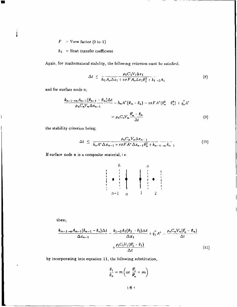
•
1 F = Vlew factor (0 to 1)
hl = Hcat transfer coefficient
Again, for mathcmatlcal stabllity, the followmg criterion must. be satu,tif'd,
(8)
and for surface node n;
= p"Cn Y.n ~~ --~~ (9) ".. 6t
the stability criterion beingi
( l 0)
If surface node n is a composite mat.erial, i e.
A B
• t t • n-l n l 2
then;
kn-l-mAn-l(On-l - On)~t _ kl_2A~OI - 02)~~ -\- q~ A. = Pnq~_!,-~(q_~_-_~,:,) 6Xn-l ~XI L':J.t
PtC l VI (0'1 - 0d +- ~t - (Il )
by incorporating into equation Il, the following substitution,
~ = m (or 6'1 = m) On lJ~
18 <
~---------------------------------------------------------- ------------

1 whcrc m - partItion coefficient
0' n
for stablllty;
k1-+ 2A 1 (mOn - (2)6t
6Xl(PnCnVn + mp1C1Vt)
(12)
(13)
The equatlOns just presented are the basis for the FASTP software These equations
arC' fllrther extcndcd to mass transfer by usmg analogous molecular properties instead of
thNmal propertlCs. The formulation of thcsc eqllations have also bcen expanded to incor-
pNate other fcatures ln the program Sllch as stlrring of a series of consecutive nodes, phase
changes and mtC'rboundary reslstance to provlde for non-Ideal contact between surfaces.
The followlng 18 a simple ex ample of a session wlth FASTP The problern solved IS
Illu~trated below.
2 () })= ïw /m - C
BRICK
What IS the temperature profile after 2 mmutes?
What is the temperature profile after 5 minutes?
What 18 the temperature profile after 10 rnmutes?
184
= 500°C
~
C
K
(Fixed dt time
2300 Kg/m 3 =
1000 0
= J/Kg- C
= 1.5 W/m-oC
= 0)

•
1
1
LJO , (''-1 "'J.N 1 1 0 ,,(II Vt (\ 1 \1\ J.l Th "N',I ~ K OR (21 MASS lRANS~ER PROBLEM •
'" III VetlA OJ.1J. El 1': ENIl-RED IN 'mltg { l"nalh ma.;!; t 1 nlP lemp f.'('~PI
1 SI ( ME'ler9 Kil (l{JramlJ Spc- den l' loi", t·, 2-HI'lflSH Fppl :..b Ih. dpo ~ Il lili HR l-NH.R " l BRlllbll
Il) CYL 1 NDE.R OR t 2) SLAB (lR (J) '>l'llfRf ' l
ENTER THE NUMBER OF DI MENS IONS 1 MAX - '1
NUMBER OF BECllUNS IN EACIl DIMENSION' IHAX 51 DIMENS (ON 1
IPIS 15 A SUMMARY OF 'fOUR ENTRIES SO FAR
VOU ARE SOLVING A HEAT lRANSHR f'ROfll!'M
IN 5 1 UNITS
FOR A SlAB
IN DIHFNSIONtSI
DI MENS ION 1 HAS 1 SECTION<;
••••••••• w •••••••••••••••••••••••••••••••••••••••••••••••••••••••••••••••• _ •••
PaulJe
Plealle press (reluru> ta continue
DO YOU WANT Ta (Il CORRECT ERRORS OR 121 f'ROCF ED • 2
<1> ENTER lHICKNESS OF EACH SElTION - ANU -NUMBER OF NOUES IJ TO 201 IN E .... CH SECTION FOR FACH DIHfNSION
SECTION 1 DIHfNSIUN 1 0 01 7
YOU ARE DEAL! NG W 1 TH SECT No 1 OF DI H No
ENTER 1 -NORMAL 2-ARITHHETIC J-GEOMETRIC 4-COMBINATION ~-YOlJr 0""1
YOIJR PROBlEH SETS UP .... S !'OLLOWS
NODE NODE. RADIUS OF NUDI': APEA vrJl UME No POSITION BOUND .... RY SPAC 1 HG
UIMENSION S~.rT 1 ON
1 Ilf1l10 01100 (}ll1 ,. fJ()(l1J IJOOH
2 (ln1? nOllu tHI 1 7 fi f}!J IJ (JI) 1 7 3 tH)' 1 noun UO T 1 l)i}!)I) 01)17 .. O(l~O 0000 1)1) 1 1 (JUO'J 1) III 7 '> 0067 OUOO 01)17 0000 0017
'" 0(1133 ,,1)00 III) 1 7 O'"H) 0017 7 (1100 uooo otJoo nOOf) f)f)1)O
Paut;{' Pl~B"le OTPOl5Cj 'rplurn.1 ta continue
185

l , l 'fI Il' 'vi AU T,r, l ,,. '1 f flll' ~ tH ,\11 rH Ir 'J .... !. 1'f."JlffIJJIIHII~I~ ,H'" L
'J~'.I 'I,~ l! Ptl"'. ({ "~{J!'I(JtJf Hl .... ~ .. r H 'II"""A' F "H l "1~ " ,1 ,tl
,~ 1 \ \ 1 'H t 1 t\ \ \. i t ~I' 1.' 1 • \ 'l, !I
1 f r ~ VII ... }. t ! ! f. ~ "L,- f tl! l t '1" f f tJ 1 f ,~
fIl. ., '1 1 A.t r ·jf1! If "l rll M Nil ftJll.1 fi ~ "1 1 RA W, 1 q, 'd fi r ,( 1 F UT
!t'If!' IHI ~Ml\lfNI HMIIRAIIII-! f-nR SII"I ",1 PI MfNt,ION' ,Il,
- l' I}/ll', III~ 1 1,llfll 1 M 1 NV(J! VI " PH"Sr 1 HMII,! ' Il
.1, AI.'f IHII ~ ANi IrllFFi'nllrJ[IAI<Y Pl',I' IMII f', <JI' f A'<lIII"tl ( nif f 1 (_ 1 r NI ( 1 1 - Y ES 2' NO 1 2
h HfllI MMH I.f/"I'I' (of ['fN' Iii Il! AI '''r' no iOU WANI TO [NItR Atl[) 1 OR CHAN' E ?
f rll f R [f ('INn [li M Ne 5 T AI f [lFNC;lfY Hf AT CM"LI1Y "ND lHERMAL CONDIICTIVlrY
T rRM NIIMlltR Ll00 100010.,
'7' ~,JARIING TfMI'fRA1URE PROFILfb
HIR SFn • 1 nF [)IM • 1 A liN 1 FORM PRor 1 L r
Il 1 LL YOU f tHER OR 2 INDIVIDUAL N(\DES
fNTf~' IHF ~;TAI'II'I" IfMPERA'!!R! '" C;Udf ',l' 11 <lN 1
4
.1-1' HDII M"N'y filAi (.~N OR HASS Al':UM IlRMS [\(1 VOt 1 W ANI Tll 1 Nf'IJT ' 0
H!lW MANY SF! nflNo., A~l 10 RE lON510ERf[1 AS STIRRED ' 0
186
/lUI

DO YOII IoIAtll TO MAY~ "UMf CIIANt,H, II' Illf INl'ttT [l ... I ... < n t DO YOII IoIMll 10 FYfCIIIF IHl Fktl',PAM '1) no 1'011 IoIMH 10 'dur rXF(ïlll{lN (.' UO YOU IoI ... NT ... SUMM"'R~ m ~ OliR 1 Nf'l (1 l'''' 1" 1 N MF M(lR, (II
••• ~ ••••••• *~ •••••••••••••••••••••••••
INI UT U"'T'" IN HEMORr
._ ....•.•.. ~ ......•...................
5i r liON THICKNESS and NUMBlH OF ~OUF5
SEC r No 1 DI H No Ulon
flOUND ... RY SURFALE CotWI flONf,
OIM No DIM No
1 EMf'n,,, 1 1I1'E <IF ~(lPI"', E. -rEHPEflHUhE l'~ 'iIPf-,t.'E N
FOR SUR~ACE 1 OF li 1 M tlo HFAT TRANSFER COlf-FICIENI AHAIENr TFMPFPATURF NO RADI,t.TION CON51m "ED
7 l'un 25 00
-IOOU ou ~lln 00
HE AT TPANS OF DIH No
C(lt'rF RADIATION AND AMBIENI TEMP FOR SIJH~A' E N 1 ARE NU T REl EV ANl
NO PHASE O,"NGES ARE 1 NVOL VEO
THERE ARE NO INTER80UNDARY RESIS1ANCE.S
THERMAL PROPERTIES
SECT OIM ST"TE DFNSITY Co y
4 23UO 0000 IOVO 000 1 <")0
bTARTING TEMPERATURES
SECT No DIH No ISTART lEHF' 25 00 SI ... rE 4 ,; r ... filS - "HALE. f- 1 XE [)
THF_RE 15 NO HEAT GENERATION
AN~LYSIS IS DONE BASED ON THE NOIlE 1 Nl ERACT 1 ON SOLUT 1 ON
THERE ARE NO STIRRED SECTIONS
••• DO YOll IoIANT 10 MAKE SOME CH!'N<;E.S If} rHE IN~UT DA!.\ Ir) Df} 1'01' IoIAtIT Ta EXECliTE litE f ROfjRAM 'l'
••• DO YOIJ IoIAtJT TO ~~IOP EXEClll 1011 (n ••• 00 YOU WANT A SUMMAR) OF YOUR 1 NPU r DA TA 1 N MlMOPY 1 1 )
187