rachel (788401) final journal
DESCRIPTION
ÂTRANSCRIPT
Studio Air.Rachel Lee (788401) | Semester 1, 2016 | Tutor: Finn

CONTENTS03
INTRODUCTION
05A.1 DESIGN FUTURING
Hoshakuji Station by Kengo Kuma & AssociatesLINK Series by Ray Power
11A.2 DESIGN COMPUTATION
Dunescape at MoMA PS1 by SHoP ArchitectsWinnipeg Skating Shelters by Patkau Architects
15A.3 COMPOSITION / GENERATION
Cliff House by Roland Snooks, KokkugiaArabesque Wall by Michael Hansmeyer & Benjamin
Dillenburger
21A.4 CONCLUSION
A.5 LEARNING OUTCOMES
22A.6 APPENDIX - ALGORITHMIC
SKETCHES
25B.1 RESEARCH FIELD
Material Performance
27B.2 CASE STUDY 1.0
Voussoir Cloud by Iwamoto Scott
35B.3 CASE STUDY 2.0
Research Pavilion 2010 by ICD/ITKE
37B.4 TECHNIQUE: DEVELOPMENT
46B.5 TECHNIQUE: PROTOTYPES
47B.6 TECHNIQUE: PROPOSAL
49B.7 LEARNING OBJECTIVES &
OUTCOMES
50B.8 APPENDIX - ALGORITHMIC
SKETCHES
53C.1 DESIGN CONCEPT
55C.2 TECTONIC ELEMENTS &
PROTOTYPES
58C.3 FINAL DETAIL MODEL
64C.4 LEARNING OBJECTIVES &
OUTCOMES
INTRODUCTION
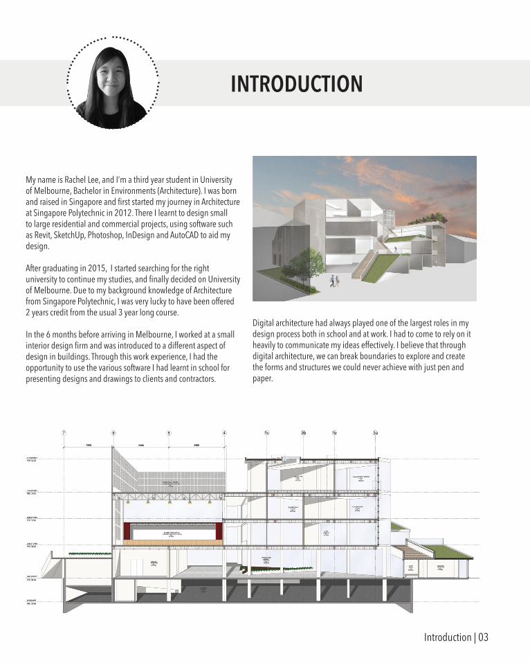
My name is Rachel Lee, and I’m a third year student in University of Melbourne, Bachelor in Environments (Architecture). I was born and raised in Singapore and first started my journey in Architecture at Singapore Polytechnic in 2012. There I learnt to design small to large residential and commercial projects, using software such as Revit, SketchUp, Photoshop, InDesign and AutoCAD to aid my design.
After graduating in 2015, I started searching for the right university to continue my studies, and finally decided on University of Melbourne. Due to my background knowledge of Architecture from Singapore Polytechnic, I was very lucky to have been offered 2 years credit from the usual 3 year long course.
In the 6 months before arriving in Melbourne, I worked at a small interior design firm and was introduced to a different aspect of design in buildings. Through this work experience, I had the opportunity to use the various software I had learnt in school for presenting designs and drawings to clients and contractors.
Digital architecture had always played one of the largest roles in my design process both in school and at work. I had to come to rely on it heavily to communicate my ideas effectively. I believe that through digital architecture, we can break boundaries to explore and create the forms and structures we could never achieve with just pen and paper.
Introduction | 03

PART A.
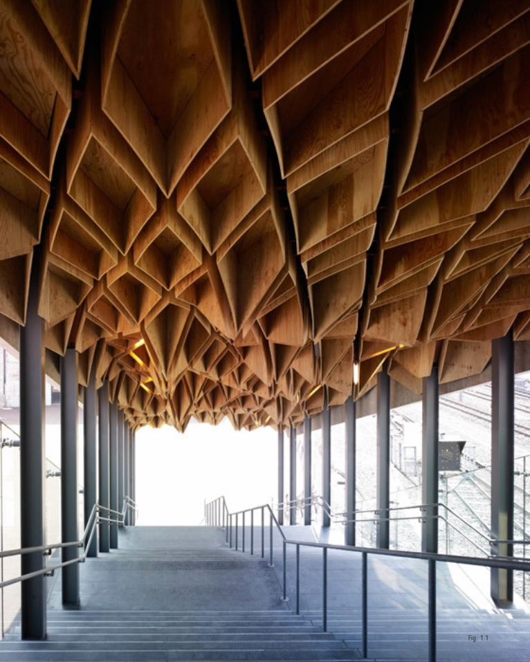
Fig. 1.1
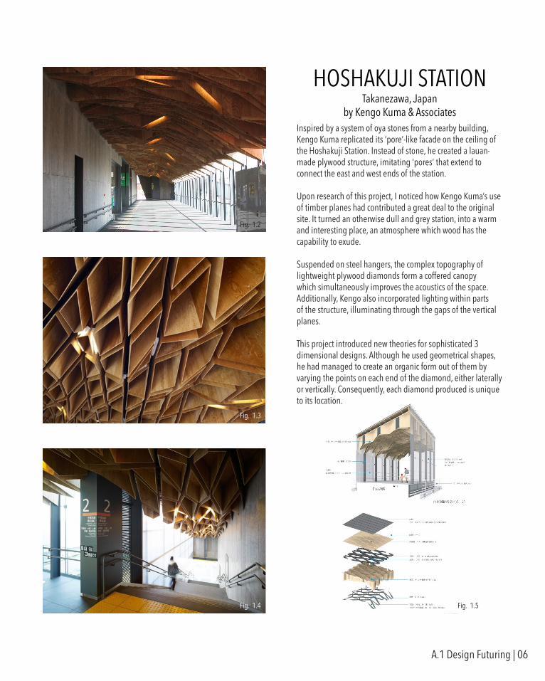
HOSHAKUJI STATIONTakanezawa, Japan
by Kengo Kuma & AssociatesInspired by a system of oya stones from a nearby building, Kengo Kuma replicated its ‘pore’-like facade on the ceiling of the Hoshakuji Station. Instead of stone, he created a lauan-made plywood structure, imitating ‘pores’ that extend to connect the east and west ends of the station.
Upon research of this project, I noticed how Kengo Kuma’s use of timber planes had contributed a great deal to the original site. It turned an otherwise dull and grey station, into a warm and interesting place, an atmosphere which wood has the capability to exude.
Suspended on steel hangers, the complex topography of lightweight plywood diamonds form a coffered canopy which simultaneously improves the acoustics of the space. Additionally, Kengo also incorporated lighting within parts of the structure, illuminating through the gaps of the vertical planes.
This project introduced new theories for sophisticated 3 dimensional designs. Although he used geometrical shapes, he had managed to create an organic form out of them by varying the points on each end of the diamond, either laterally or vertically. Consequently, each diamond produced is unique to its location.
Fig. 1.2
Fig. 1.3
Fig. 1.4 Fig. 1.5
A.1 Design Futuring | 06

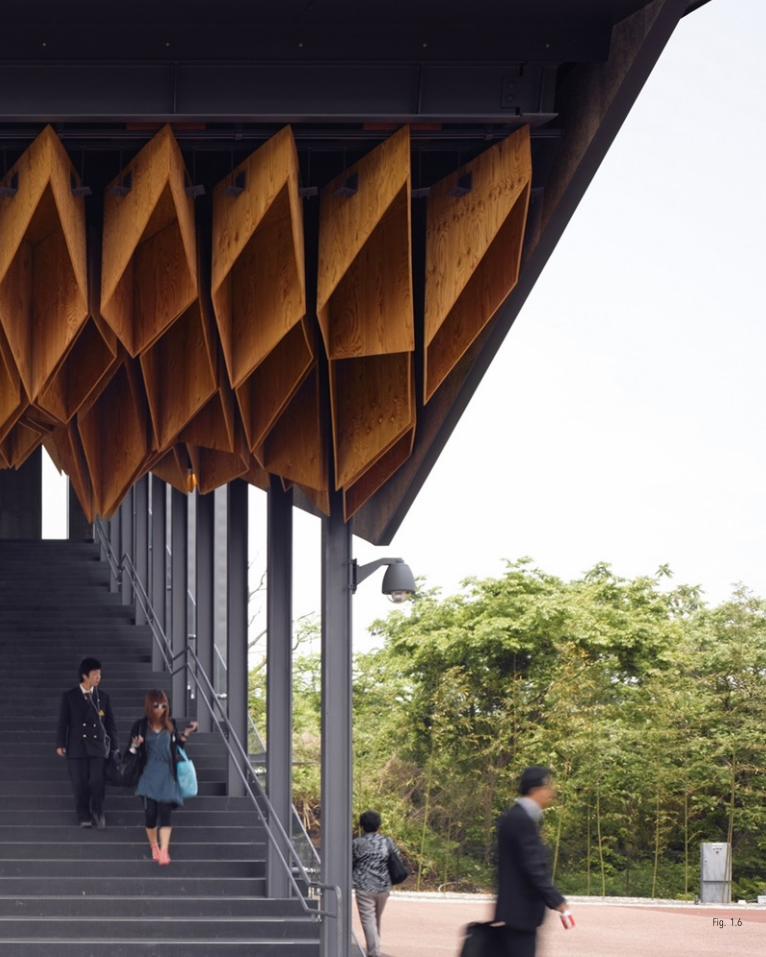
Fig. 1.6
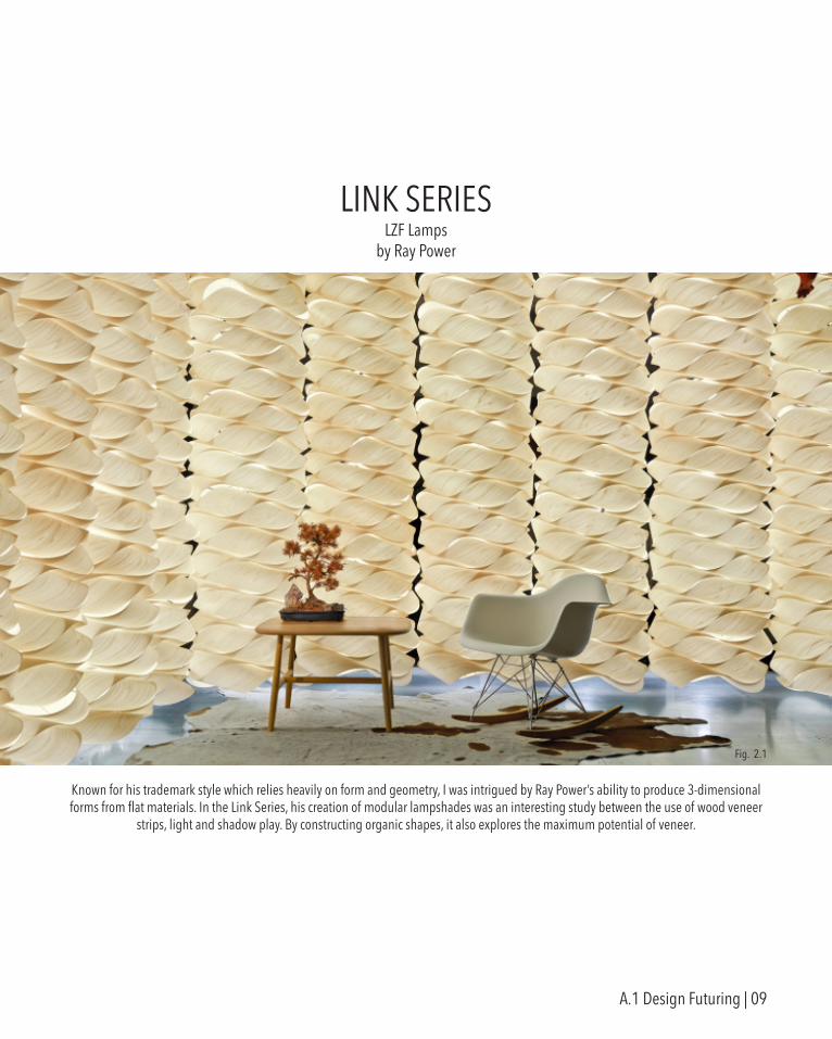
LINK SERIESLZF Lamps
by Ray Power
Known for his trademark style which relies heavily on form and geometry, I was intrigued by Ray Power’s ability to produce 3-dimensional forms from flat materials. In the Link Series, his creation of modular lampshades was an interesting study between the use of wood veneer
strips, light and shadow play. By constructing organic shapes, it also explores the maximum potential of veneer.
Fig. 2.1
A.1 Design Futuring | 09
Being modular, the idea to stack each lampshade on top of one another not only increases illumination, as a lamp should, but also produces a sculptural art piece. Which, depending on the veneer colour, brings out a different kind of ambience.
The pattern in which the veneer strip was arranged is the Möbius strip. A non-orientable surface that consists of a half twist in a closed band.
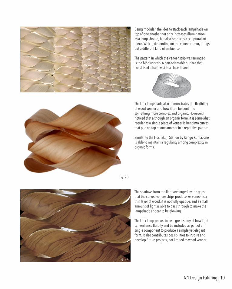
The Link lampshade also demonstrates the flexibility of wood veneer and how it can be bent into something more complex and organic. However, I noticed that although an organic form, it is somewhat regular as a single piece of veneer is bent into curves that pile on top of one another in a repetitive pattern.
Similar to the Hoshakuji Station by Kengo Kuma, one is able to maintain a regularity among complexity in organic forms.
The shadows from the light are forged by the gaps that the curved veneer strips produce. As veneer is a thin layer of wood, it is not fully opaque, and a small amount of light is able to pass through to make the lampshade appear to be glowing.
The Link lamp proves to be a great study of how light can enhance fluidity and be included as part of a single component to produce a simple yet elegant form. It also contributes possibilities to inspire and develop future projects, not limited to wood veneer.
Fig. 2.3
Fig. 2.4
Fig. 2.2
A.1 Design Futuring | 10
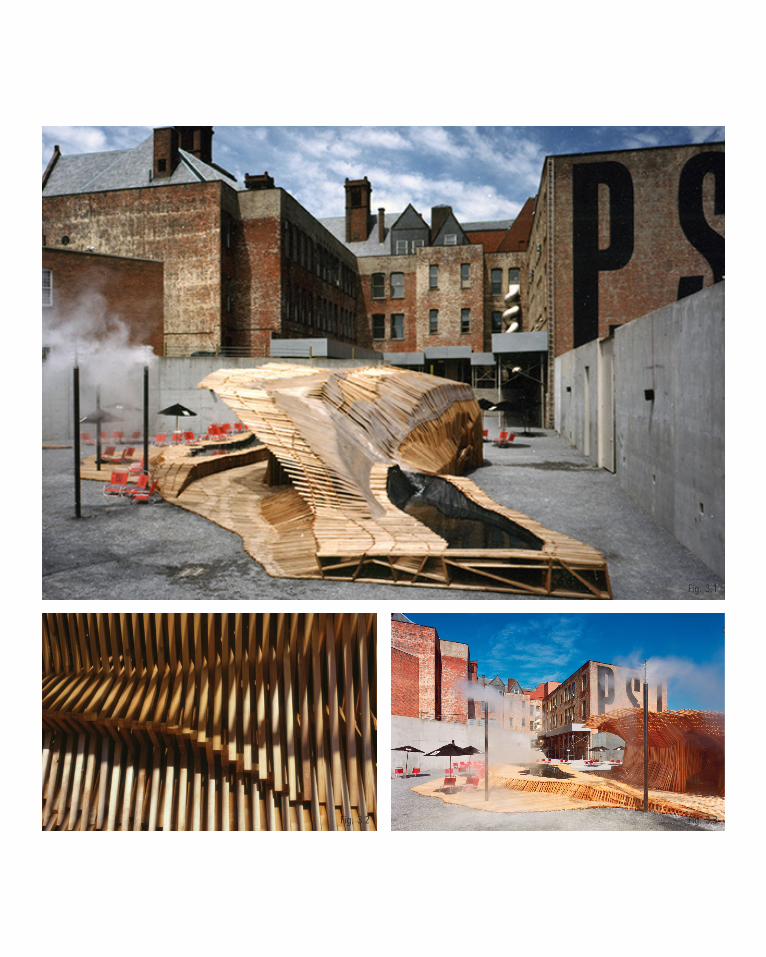
Fig. 3.1
Fig. 3.3Fig. 3.2
DUNESCAPEMoMA PS1, New York
by SHoP Architects
SHoP Architect’s philosophy is guided by performance-based design, in which form maximizes the capabilities of a building. Every building looks different and each has its own function.
This temporary installation in New York was their conception of an “urban beach”. Designed for MoMA PS1’s summer music event, and with added features like spraying water mist and a small wading pool, the structure provided a communal lounging space for people to take shelter from the summer heat.
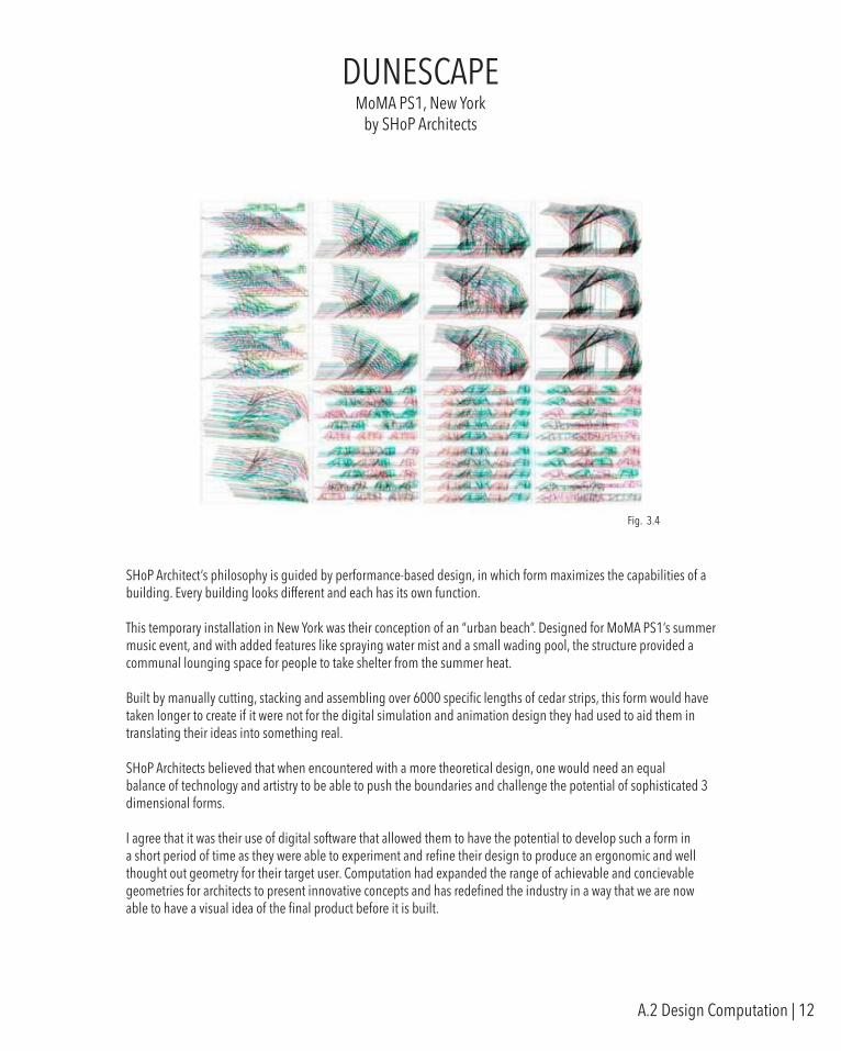
Built by manually cutting, stacking and assembling over 6000 specific lengths of cedar strips, this form would have taken longer to create if it were not for the digital simulation and animation design they had used to aid them in translating their ideas into something real.
SHoP Architects believed that when encountered with a more theoretical design, one would need an equal balance of technology and artistry to be able to push the boundaries and challenge the potential of sophisticated 3 dimensional forms.
I agree that it was their use of digital software that allowed them to have the potential to develop such a form in a short period of time as they were able to experiment and refine their design to produce an ergonomic and well thought out geometry for their target user. Computation had expanded the range of achievable and concievable geometries for architects to present innovative concepts and has redefined the industry in a way that we are now able to have a visual idea of the final product before it is built.
Fig. 3.4
A.2 Design Computation | 12
WINNIPEG SKATING SHELTERSWinnipeg, Canada
by Patkau Architects
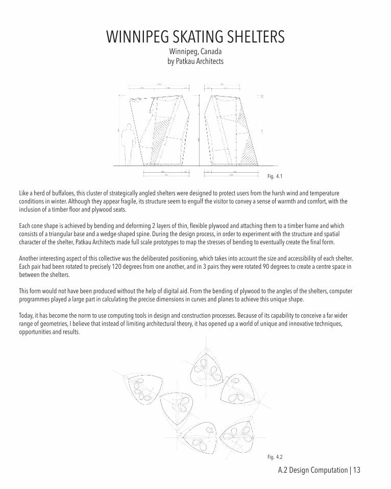
Like a herd of buffaloes, this cluster of strategically angled shelters were designed to protect users from the harsh wind and temperature conditions in winter. Although they appear fragile, its structure seem to engulf the visitor to convey a sense of warmth and comfort, with the inclusion of a timber floor and plywood seats.
Each cone shape is achieved by bending and deforming 2 layers of thin, flexible plywood and attaching them to a timber frame and which consists of a triangular base and a wedge-shaped spine. During the design process, in order to experiment with the structure and spatial character of the shelter, Patkau Architects made full scale prototypes to map the stresses of bending to eventually create the final form.
Another interesting aspect of this collective was the deliberated positioning, which takes into account the size and accessibility of each shelter. Each pair had been rotated to precisely 120 degrees from one another, and in 3 pairs they were rotated 90 degrees to create a centre space in between the shelters.
This form would not have been produced without the help of digital aid. From the bending of plywood to the angles of the shelters, computer programmes played a large part in calculating the precise dimensions in curves and planes to achieve this unique shape.
Today, it has become the norm to use computing tools in design and construction processes. Because of its capability to conceive a far wider range of geometries, I believe that instead of limiting architectural theory, it has opened up a world of unique and innovative techniques, opportunities and results.
Fig. 4.1
Fig. 4.2
A.2 Design Computation | 13
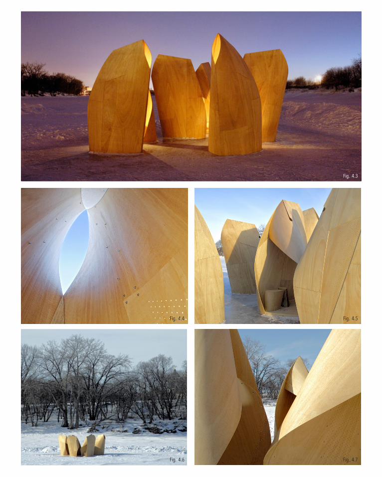
Fig. 4.3
Fig. 4.5
Fig. 4.7Fig. 4.6
Fig. 4.4
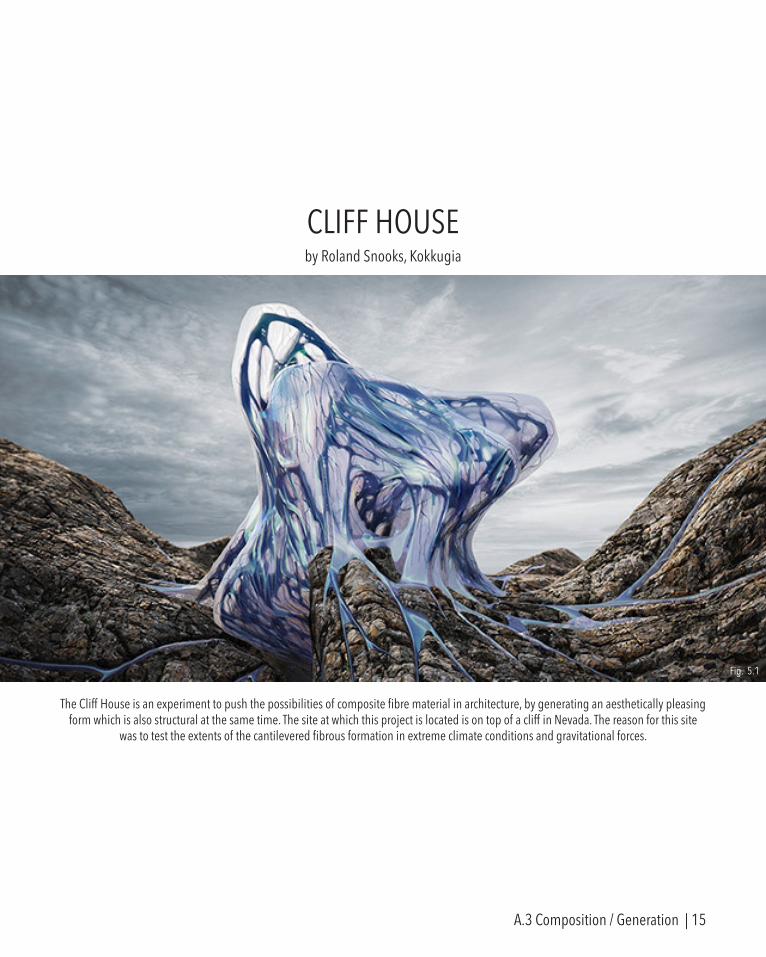
CLIFF HOUSEby Roland Snooks, Kokkugia
The Cliff House is an experiment to push the possibilities of composite fibre material in architecture, by generating an aesthetically pleasing form which is also structural at the same time. The site at which this project is located is on top of a cliff in Nevada. The reason for this site
was to test the extents of the cantilevered fibrous formation in extreme climate conditions and gravitational forces.
Fig. 5.1
A.3 Composition / Generation | 15
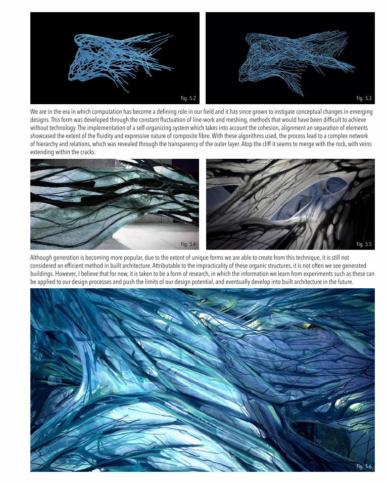
We are in the era in which computation has become a defining role in our field and it has since grown to instigate conceptual changes in emerging designs. This form was developed through the constant fluctuation of line-work and meshing, methods that would have been difficult to achieve without technology. The implementation of a self-organizing system which takes into account the cohesion, alignment an separation of elements showcased the extent of the fluidity and expressive nature of composite fibre. With these algorithms used, the process lead to a complex network of hierarchy and relations, which was revealed through the transparency of the outer layer. Atop the cliff it seems to merge with the rock, with veins extending within the cracks.
Although generation is becoming more popular, due to the extent of unique forms we are able to create from this technique, it is still not considered an efficient method in built architecture. Attributable to the impracticality of these organic structures, it is not often we see generated buildings. However, I believe that for now, it is taken to be a form of research, in which the information we learn from experiments such as these can be applied to our design processes and push the limits of our design potential, and eventually develop into built architecture in the future.
Fig. 5.4
Fig. 5.2
Fig. 5.5
Fig. 5.6
Fig. 5.3
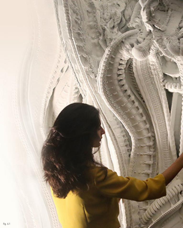
Fig. 6.1
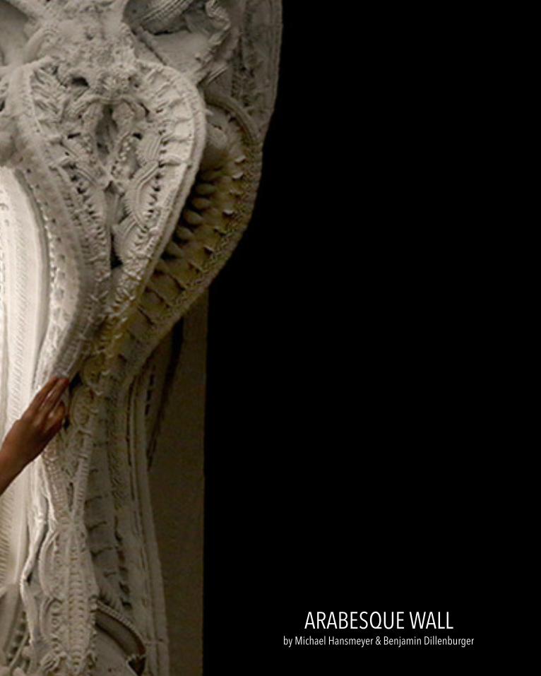
ARABESQUE WALLby Michael Hansmeyer & Benjamin Dillenburger
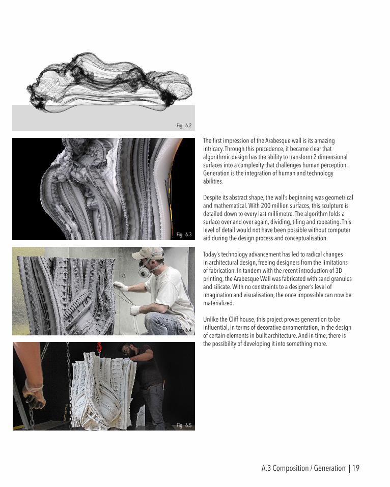
The first impression of the Arabesque wall is its amazing intricacy. Through this precedence, it became clear that algorithmic design has the ability to transform 2 dimensional surfaces into a complexity that challenges human perception. Generation is the integration of human and technology abilities.
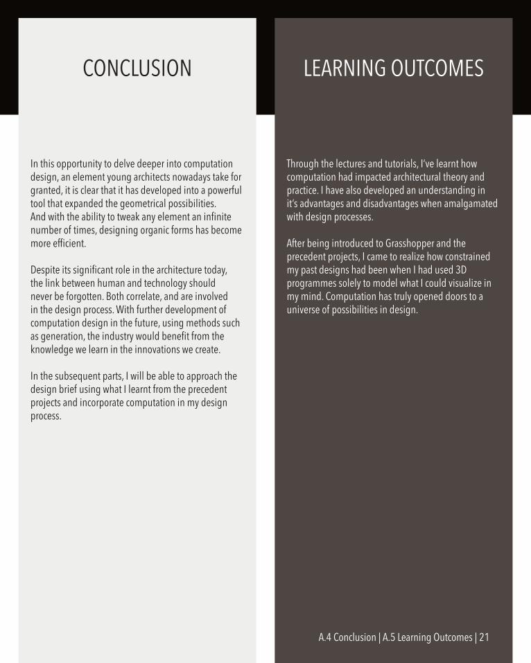
Despite its abstract shape, the wall’s beginning was geometrical and mathematical. With 200 million surfaces, this sculpture is detailed down to every last millimetre. The algorithm folds a surface over and over again, dividing, tiling and repeating. This level of detail would not have been possible without computer aid during the design process and conceptualisation.
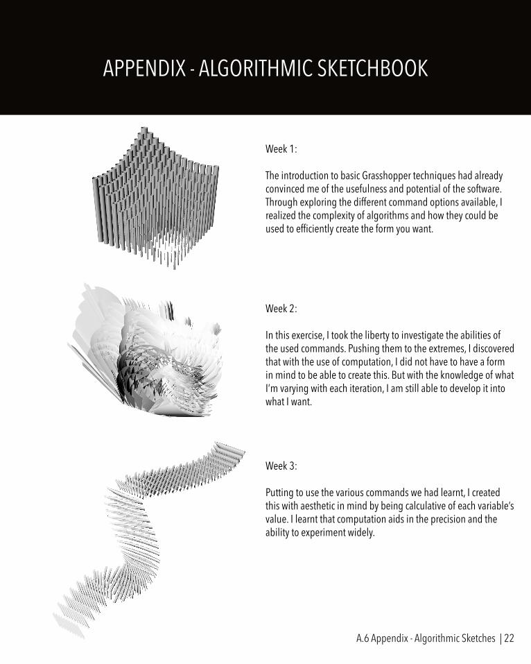
Today’s technology advancement has led to radical changes in architectural design, freeing designers from the limitations of fabrication. In tandem with the recent introduction of 3D printing, the Arabesque Wall was fabricated with sand granules and silicate. With no constraints to a designer’s level of imagination and visualisation, the once impossible can now be materialized.
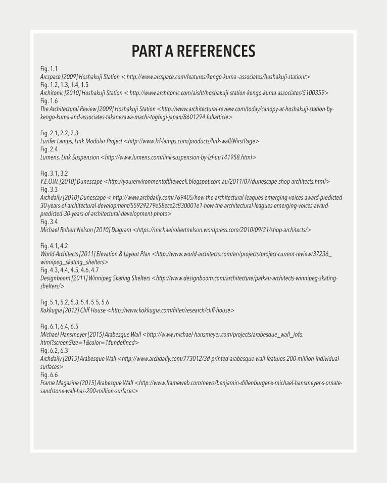
Unlike the Cliff house, this project proves generation to be influential, in terms of decorative ornamentation, in the design of certain elements in built architecture. And in time, there is the possibility of developing it into something more.
Fig. 6.2
Fig. 6.3
Fig. 6.4
Fig. 6.5
A.3 Composition / Generation | 19

Fig. 6.6
In this opportunity to delve deeper into computation design, an element young architects nowadays take for granted, it is clear that it has developed into a powerful tool that expanded the geometrical possibilities. And with the ability to tweak any element an infinite number of times, designing organic forms has become more efficient.
Despite its significant role in the architecture today, the link between human and technology should never be forgotten. Both correlate, and are involved in the design process. With further development of computation design in the future, using methods such as generation, the industry would benefit from the knowledge we learn in the innovations we create.
In the subsequent parts, I will be able to approach the design brief using what I learnt from the precedent projects and incorporate computation in my design process.
Through the lectures and tutorials, I’ve learnt how computation had impacted architectural theory and practice. I have also developed an understanding in it’s advantages and disadvantages when amalgamated with design processes.
After being introduced to Grasshopper and the precedent projects, I came to realize how constrained my past designs had been when I had used 3D programmes solely to model what I could visualize in my mind. Computation has truly opened doors to a universe of possibilities in design.
CONCLUSION LEARNING OUTCOMES
A.4 Conclusion | A.5 Learning Outcomes | 21
APPENDIX - ALGORITHMIC SKETCHBOOK
Week 1:
The introduction to basic Grasshopper techniques had already convinced me of the usefulness and potential of the software. Through exploring the different command options available, I realized the complexity of algorithms and how they could be used to efficiently create the form you want.
Week 2:
In this exercise, I took the liberty to investigate the abilities of the used commands. Pushing them to the extremes, I discovered that with the use of computation, I did not have to have a form in mind to be able to create this. But with the knowledge of what I’m varying with each iteration, I am still able to develop it into what I want.
Week 3:
Putting to use the various commands we had learnt, I created this with aesthetic in mind by being calculative of each variable’s value. I learnt that computation aids in the precision and the ability to experiment widely.
A.6 Appendix - Algorithmic Sketches | 22
PART A REFERENCESFig. 1.1Arcspace [2009] Hoshakuji Station < http://www.arcspace.com/features/kengo-kuma--associates/hoshakuji-station/>Fig. 1.2, 1.3, 1.4, 1.5Architonic [2010] Hoshakuji Station < http://www.architonic.com/aisht/hoshakuji-station-kengo-kuma-associates/5100359>Fig. 1.6 The Architectural Review [2009] Hoshakuji Station <http://www.architectural-review.com/today/canopy-at-hoshakuji-station-by-kengo-kuma-and-associates-takanezawa-machi-toghigi-japan/8601294.fullarticle>
Fig. 2.1, 2.2, 2.3Luzifer Lamps, Link Modular Project <http://www.lzf-lamps.com/products/link-wall/#firstPage>Fig. 2.4Lumens, Link Suspension <http://www.lumens.com/link-suspension-by-lzf-uu141958.html>
Fig. 3.1, 3.2Y.E.O.W. [2010] Dunescape <http://yourenvironmentoftheweek.blogspot.com.au/2011/07/dunescape-shop-architects.html>Fig. 3.3Archdaily [2010] Dunescape < http://www.archdaily.com/769405/how-the-architectural-leagues-emerging-voices-award-predicted-30-years-of-architectural-development/55929279e58ece2c830001e1-how-the-architectural-leagues-emerging-voices-award-predicted-30-years-of-architectural-development-photo>Fig. 3.4Michael Robert Nelson [2010] Diagram <https://michaelrobertnelson.wordpress.com/2010/09/21/shop-architects/>
Fig. 4.1, 4.2World-Architects [2011] Elevation & Layout Plan <http://www.world-architects.com/en/projects/project-current-review/37236_winnipeg_skating_shelters>Fig. 4.3, 4.4, 4.5, 4.6, 4.7Designboom [2011] Winnipeg Skating Shelters <http://www.designboom.com/architecture/patkau-architects-winnipeg-skating-shelters/>
Fig. 5.1, 5.2, 5.3, 5.4, 5.5, 5.6Kokkugia [2012] Cliff House <http://www.kokkugia.com/filter/research/cliff-house>
Fig. 6.1, 6.4, 6.5Michael Hansmeyer [2015] Arabesque Wall <http://www.michael-hansmeyer.com/projects/arabesque_wall_info.html?screenSize=1&color=1#undefined>Fig. 6.2, 6.3Archdaily [2015] Arabesque Wall <http://www.archdaily.com/773012/3d-printed-arabesque-wall-features-200-million-individual-surfaces>Fig. 6.6Frame Magazine [2015] Arabesque Wall <http://www.frameweb.com/news/benjamin-dillenburger-x-michael-hansmeyer-s-ornate-sandstone-wall-has-200-million-surfaces>

PART B.
MATERIAL PERFORMANCE
RESEARCH FIELD
As we were tasked to create a ceiling installation, I chose Material Performance as my starting research field, in order to study the potential of the material we would be using in our design: Wood Veneer. Every material has its own properties. Through research, one would
easily be able to find out how a material would perform under different environments. But when paired with parametric design tools, the opportunities to use those properties to aid or be apart of our conceptual designs is at our disposal.
Taking for example the projects which have considered material performance in their form-finding process, such as the Voussoir Cloud by Iwamoto and the Research Pavilion 2010 by ICD and ITKE, the potential of wood performance is demonstrated. For instance, the
Research Pavilion was based entirely on the elastic bending behaviour of birch plywood strips. The design process involved countless physical experiments and calculations to define and embed the material behaviour features in parametric principles. The outcome that was fabricated, proved the integration of design computation and materialization to be valuable. And with the assistance of parametric design
tools and today’s technology, the option to even alter a material’s behaviour is possible.
Similarly, the approach of analysing the material’s performance can be adopted when designing the ceiling installation. Rather than be reliant on its properties, we should instead utilize them for our designs.
B.1 Research Field | 25
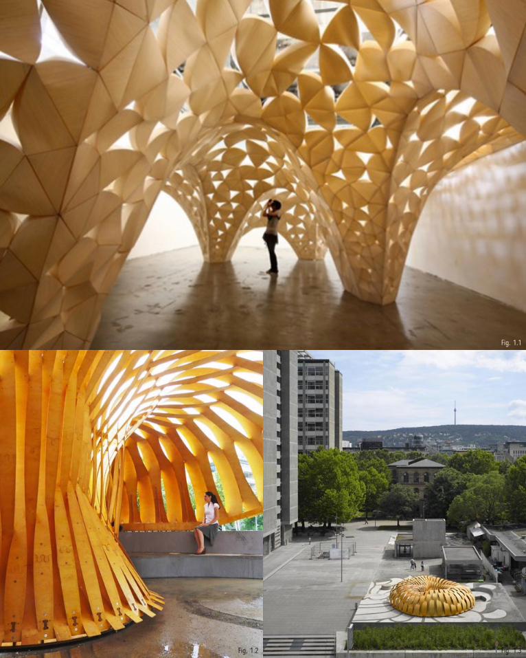
Fig. 1.1
Fig. 1.3Fig. 1.2

CASE STUDY 1.0
The Voussoir Cloud installation is a porous surface made of compressive wood elements, assembled into a system of self-supporting vault structures. Its combines light and luminous wood laminate and the effects of compression to explore the structural potential . Formed
from numerous 3 dimensional petals joined together, this project pushes the limits of wood laminate to create a more complex structural configuration.
To recreate the Voussoir Cloud, the Grasshopper definition begins with the voronoi component to segregate and define the number of vaults. The algorithm also includes Kangaroo, a physics tool which produces a simulation of the model when affected by gravitational forces
and pressures whilst constrained at certain points, in order to optimize the overall form of each vault.
Relating to the project brief, this project provoked critical factors I needed to consider for the ceiling installation. Such as; how can wood veneer be modified to be structurally self-supported, and how can i push the boundaries of wood veneer physically to replicate what is
modelled digitally.
Voussoir Cloud by Iwamoto Scott
Fig. 2.1
B.2 Case Study 1.0 | 27

SELECTION CRITERIA
The site for the ceiling installation is located in an office. The following are criteria for the ceiling installation to suit the allocated space.
1. ACOUSTICS
In an office, meetings and discussions are held regularly. The design should improve the acoustics of the interior space by absorbing,blocking and reflecting sounds.
2. SHADOWS & LIGHTING
As the installation will be mounted on the ceiling, lights can be integrated in the design or used to enhance the effects of shadows or lighting in the space.
3. AESTHETICS
The use of wood veneer can create a warm atmosphere which is suitable form for a working environment. Similarly, the form should be perceived as an art piece to beautify the office space. 4. STRUCTURE
The only support the structure would have is from the ceiling, for example by hanging the installation from rods. Hence, the design would have to be self-supportive for it to be held up in place.
5. CONSTRUCTIBILITY
The model has to be possible to fabricate to assemble and build, in order for the design to be feasible. To install on the ceiling, wood veneer should not be used in excess to keep the structure relatively lightweight.
Fig. 2.2 Fig. 2.3 Fig. 2.4
B.2 Case Study 1.0 | 28
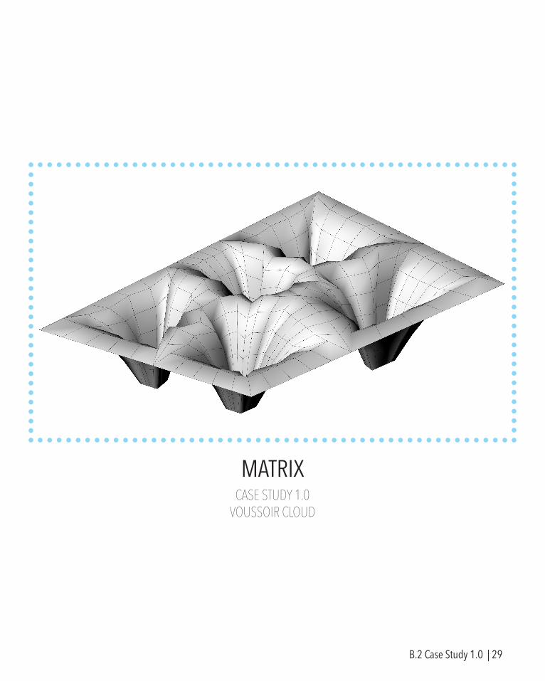
MATRIXCASE STUDY 1.0
VOUSSOIR CLOUD
B.2 Case Study 1.0 | 29
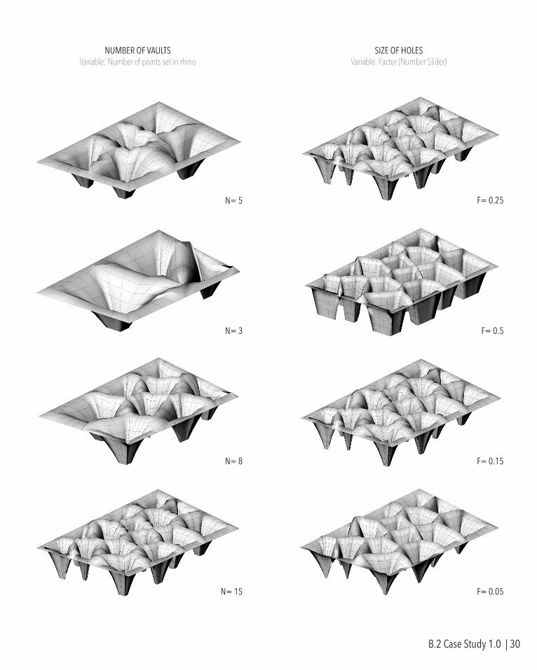
NUMBER OF VAULTSVariable: Number of points set in rhino
SIZE OF HOLESVariable: Factor (Number Slider)
N= 5 F= 0.25
N= 3 F= 0.5
N= 8 F= 0.15
N= 15 F= 0.05
B.2 Case Study 1.0 | 30
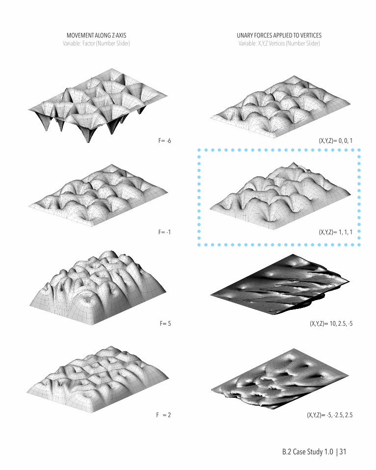
MOVEMENT ALONG Z-AXISVariable: Factor (Number Slider)
UNARY FORCES APPLIED TO VERTICESVariable: X,Y,Z Vertices (Number Slider)
F= -6 (X,Y,Z)= 0, 0, 1
(X,Y,Z)= 1, 1, 1
(X,Y,Z)= 10, 2.5, -5
(X,Y,Z)= -5, -2.5, 2.5
F= -1
F= 5
F = 2
B.2 Case Study 1.0 | 31
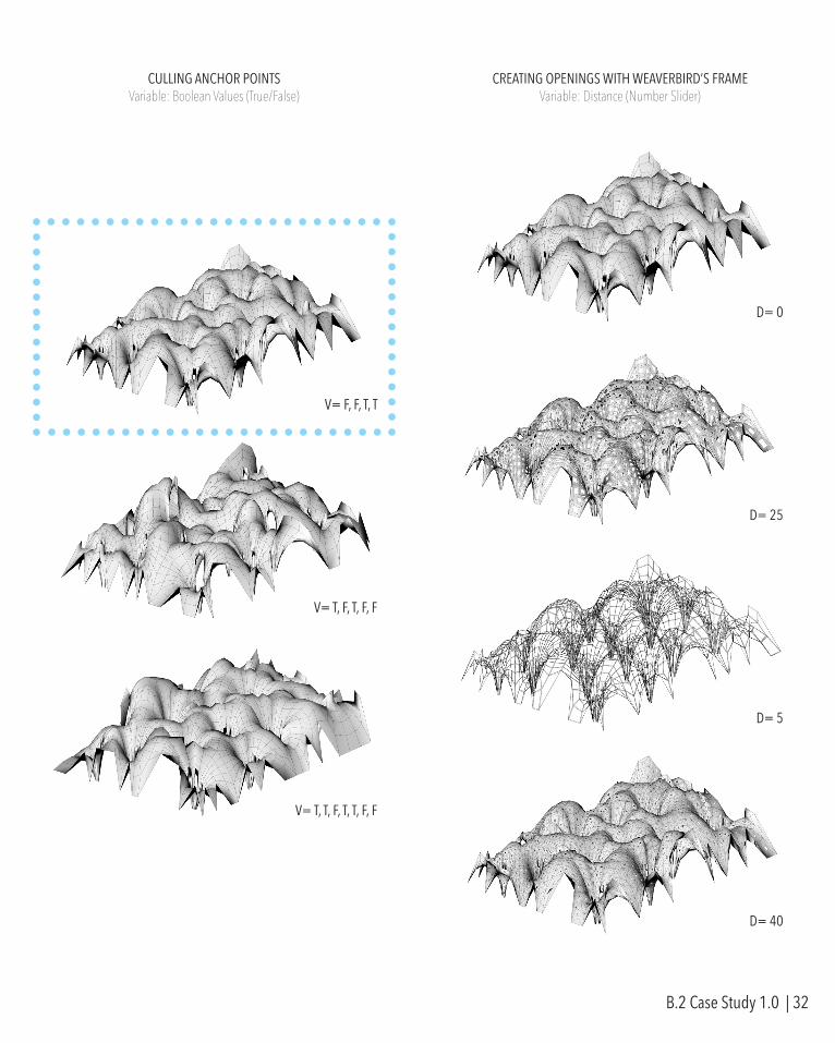
CULLING ANCHOR POINTSVariable: Boolean Values (True/False)
CREATING OPENINGS WITH WEAVERBIRD’S FRAMEVariable: Distance (Number Slider)
V= F, F, T, T
V= T, F, T, F, F
V= T, T, F, T, T, F, F
D= 25
D= 0
D= 5
D= 40
B.2 Case Study 1.0 | 32
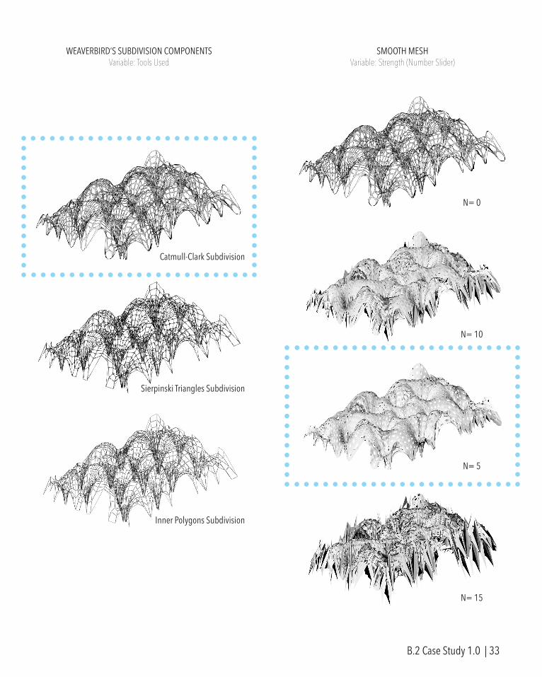
WEAVERBIRD’S SUBDIVISION COMPONENTSVariable: Tools Used
SMOOTH MESHVariable: Strength (Number Slider)
Catmull-Clark Subdivision
Sierpinski Triangles Subdivision
Inner Polygons Subdivision
N= 0
N= 10
N= 5
N= 15
B.2 Case Study 1.0 | 33
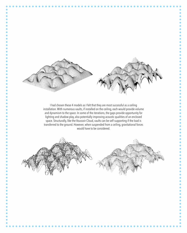
I had chosen these 4 models as I felt that they are most successful as a ceiling installation. With numerous vaults, if installed on the ceiling, each would provide volume
and dynamism to the space. In some of the iterations, the gaps provide opportunity for lighting and shadow play, also potentially improving acoustic qualities of an enclosed space. Structurally, like the Voussoir Cloud, vaults can be self supporting if the load is
transferred to the ground. However, when suspended from a ceiling, gravitational forces would have to be considered.
REVERSE ENGINEERINGCASE STUDY 2.0
RESEARCH PAVILION 2010
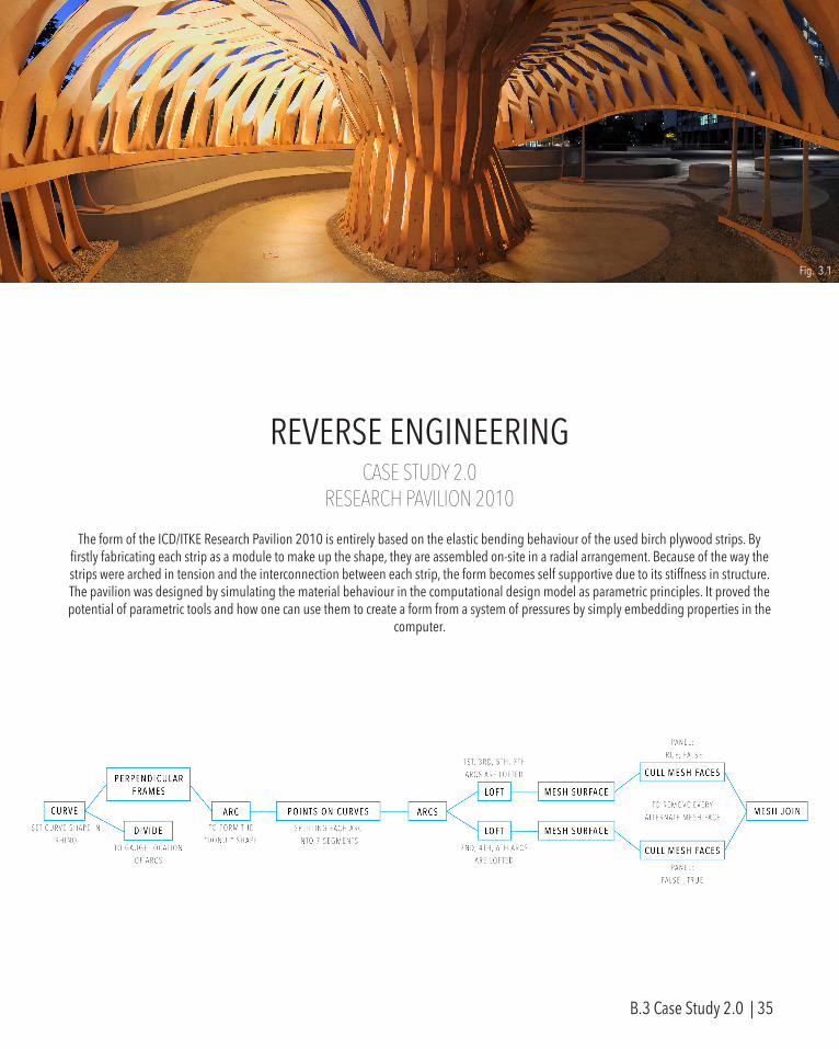
The form of the ICD/ITKE Research Pavilion 2010 is entirely based on the elastic bending behaviour of the used birch plywood strips. By firstly fabricating each strip as a module to make up the shape, they are assembled on-site in a radial arrangement. Because of the way the strips were arched in tension and the interconnection between each strip, the form becomes self supportive due to its stiffness in structure. The pavilion was designed by simulating the material behaviour in the computational design model as parametric principles. It proved the potential of parametric tools and how one can use them to create a form from a system of pressures by simply embedding properties in the
computer.
Fig. 3.1
B.3 Case Study 2.0 | 35
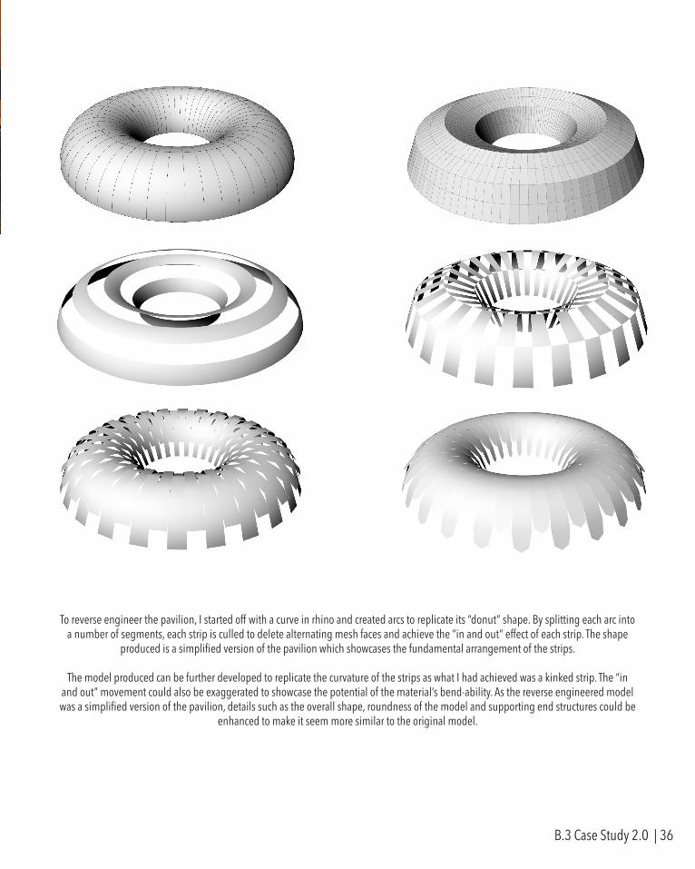
To reverse engineer the pavilion, I started off with a curve in rhino and created arcs to replicate its “donut” shape. By splitting each arc into a number of segments, each strip is culled to delete alternating mesh faces and achieve the “in and out” effect of each strip. The shape
produced is a simplified version of the pavilion which showcases the fundamental arrangement of the strips.
The model produced can be further developed to replicate the curvature of the strips as what I had achieved was a kinked strip. The “in and out” movement could also be exaggerated to showcase the potential of the material’s bend-ability. As the reverse engineered model was a simplified version of the pavilion, details such as the overall shape, roundness of the model and supporting end structures could be
enhanced to make it seem more similar to the original model.
B.3 Case Study 2.0 | 36

MATRIXTECHNIQUE: DEVELOPMENTRESEARCH PAVILION 2010
B.4 Technique: Development | 37
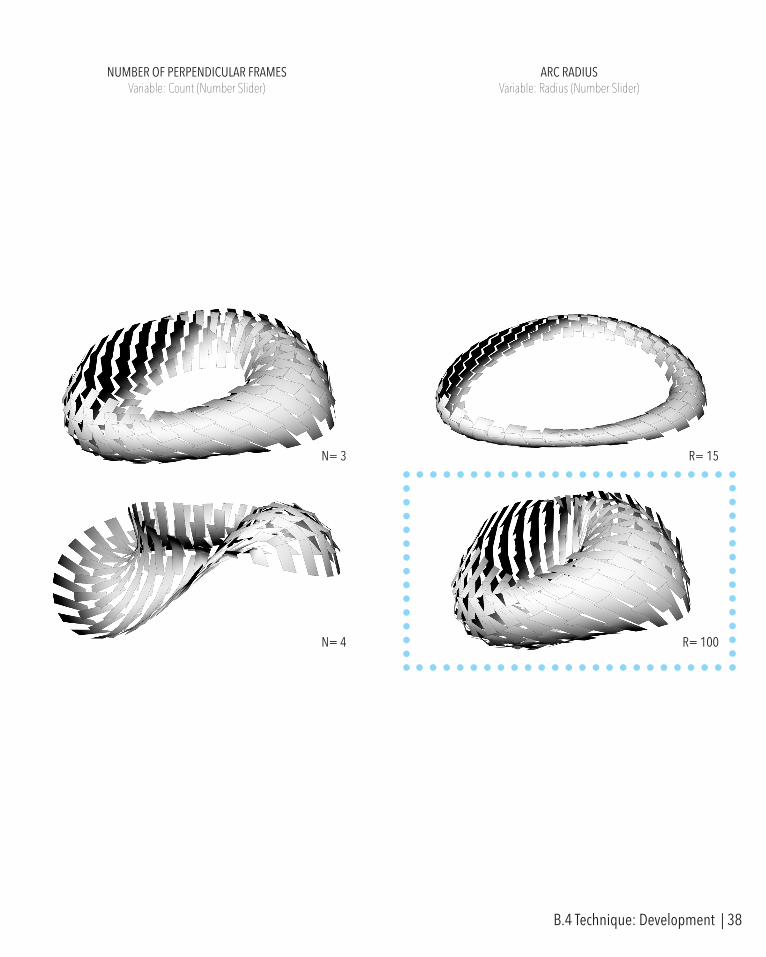
NUMBER OF PERPENDICULAR FRAMESVariable: Count (Number Slider)
ARC RADIUSVariable: Radius (Number Slider)
N= 3 R= 15
N= 4 R= 100
B.4 Technique: Development | 38
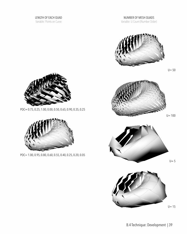
NUMBER OF MESH QUADSVariable: U Count (Number Slider)
U= 100
U= 50
U= 5
U= 15
LENGTH OF EACH QUADVariable: Points on Curve
POC= 0.75, 0.25, 1.00, 0.00, 0.50, 0.65, 0.90, 0.35, 0.25
POC= 1.00, 0.95, 0.80, 0.60, 0.55, 0.40, 0.25, 0.20, 0.05
B.4 Technique: Development | 39

USING WEAVERBIRD’S SIERPINSKI CARPETVariable: Distance (Number Slider)
CULLING MESH FACESVariable: Boolean Values (True/False)
D= 5
D= 1
D= 25
D= 50
V= T, F, F // F, T, T
V= T, F // F, T
V= F // F
V= T, F, F, T // F, F, T, T
B.4 Technique: Development | 40
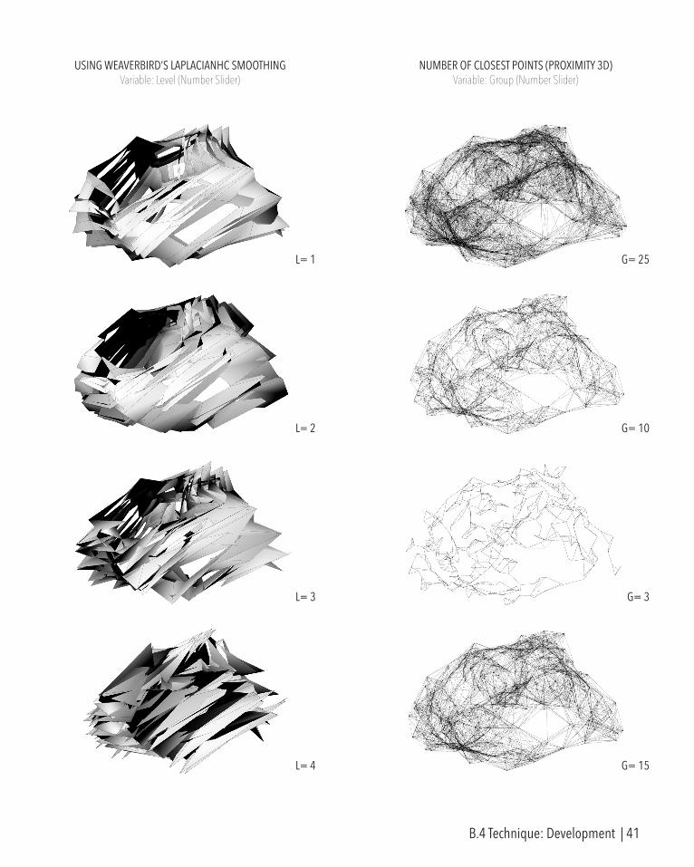
NUMBER OF CLOSEST POINTS (PROXIMITY 3D)Variable: Group (Number Slider)
G= 25
G= 10
G= 3
G= 15
USING WEAVERBIRD’S LAPLACIANHC SMOOTHINGVariable: Level (Number Slider)
L= 1
L= 2
L= 3
L= 4
B.4 Technique: Development | 41

CULLING MESH VERTICESVariable: Boolean Values (True/False)
CULLING POINTS TO LOFTVariable: Boolean Values (True/False)
V= F, F, T, T V= F, T, F, F
V= F, T
V= F, F, T
V= T, F, F, T
V= F, T
V= T, F
V= T, F, F, T
B.4 Technique: Development | 42
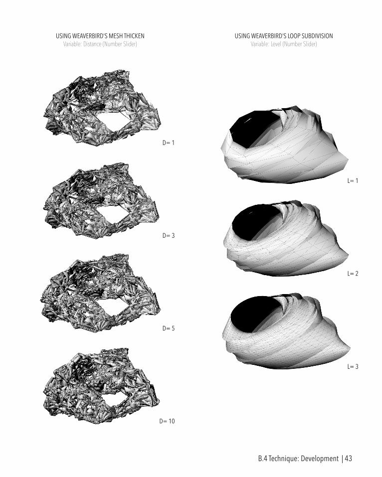
USING WEAVERBIRD’S LOOP SUBDIVISIONVariable: Level (Number Slider)
L= 1
L= 3
L= 2
USING WEAVERBIRD’S MESH THICKENVariable: Distance (Number Slider)
D= 1
D= 3
D= 5
D= 10
B.4 Technique: Development | 43
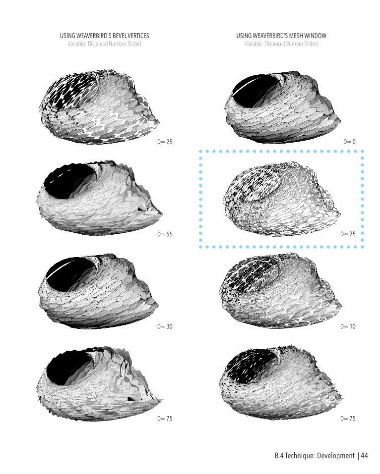
USING WEAVERBIRD’S MESH WINDOWVariable: Distance (Number Slider)
USING WEAVERBIRD’S BEVEL VERTICESVariable: Distance (Number Slider)
D= 25 D= 0
D= 25
D= 10
D= 75
D= 55
D= 30
D= 75
B.4 Technique: Development | 44
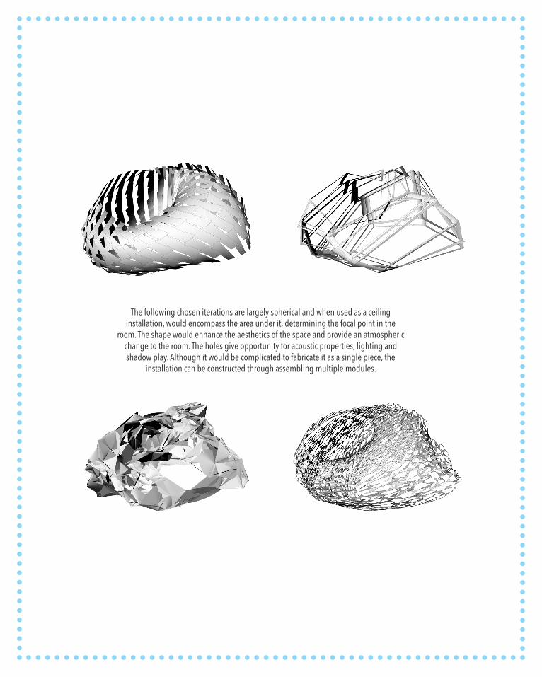
The following chosen iterations are largely spherical and when used as a ceiling installation, would encompass the area under it, determining the focal point in the
room. The shape would enhance the aesthetics of the space and provide an atmospheric change to the room. The holes give opportunity for acoustic properties, lighting and shadow play. Although it would be complicated to fabricate it as a single piece, the
installation can be constructed through assembling multiple modules.
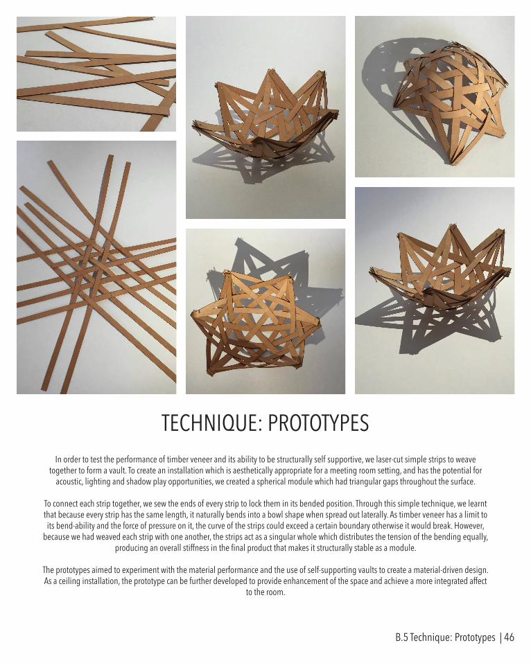
In order to test the performance of timber veneer and its ability to be structurally self supportive, we laser-cut simple strips to weave together to form a vault. To create an installation which is aesthetically appropriate for a meeting room setting, and has the potential for
acoustic, lighting and shadow play opportunities, we created a spherical module which had triangular gaps throughout the surface.
To connect each strip together, we sew the ends of every strip to lock them in its bended position. Through this simple technique, we learnt that because every strip has the same length, it naturally bends into a bowl shape when spread out laterally. As timber veneer has a limit to its bend-ability and the force of pressure on it, the curve of the strips could exceed a certain boundary otherwise it would break. However,
because we had weaved each strip with one another, the strips act as a singular whole which distributes the tension of the bending equally, producing an overall stiffness in the final product that makes it structurally stable as a module.
The prototypes aimed to experiment with the material performance and the use of self-supporting vaults to create a material-driven design. As a ceiling installation, the prototype can be further developed to provide enhancement of the space and achieve a more integrated affect
to the room.
TECHNIQUE: PROTOTYPES
B.5 Technique: Prototypes | 46
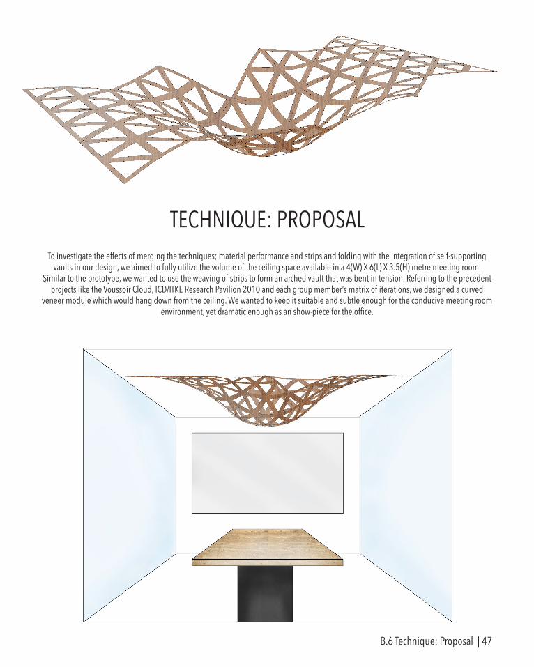
TECHNIQUE: PROPOSALTo investigate the effects of merging the techniques; material performance and strips and folding with the integration of self-supporting
vaults in our design, we aimed to fully utilize the volume of the ceiling space available in a 4(W) X 6(L) X 3.5(H) metre meeting room. Similar to the prototype, we wanted to use the weaving of strips to form an arched vault that was bent in tension. Referring to the precedent
projects like the Voussoir Cloud, ICD/ITKE Research Pavilion 2010 and each group member’s matrix of iterations, we designed a curved veneer module which would hang down from the ceiling. We wanted to keep it suitable and subtle enough for the conducive meeting room
environment, yet dramatic enough as an show-piece for the office.
B.6 Technique: Proposal | 47

The model we created suited our selection criteria for a ceiling installation. The gaps along the surface and the organic form can contribute to the acoustics of the space and also provides opportunities for installation of lighting fixtures in the ceiling, casting interesting shadows in the room. As the form is not too complex, it can be structurally stable and easily fabricated and assembled.
The Grasshopper script was developed by using a triangular grid as a starting geometry. Using the Weaverbird’s Sierpinski Carpet tool, I created a mesh of strips and triangular holes in the surface. To create an spherical vault, I used the simple method of 3 varying sizes of circles on top of one another, to easily toggle the curvature of the vault. The Sierpinski mesh was then projected onto the lofted surface of the vault.
As our concept included weaving, I found it difficult to portray the weaving among the strips and opted for a simplified model to showcase the form during interim. I believe that the Grasshopper definition can be pushed further and developed into a more accurate representation of what our group designed. The Kangaroo plug-in could be used to directly alter the gravitational forces to create vaults instead.
As we had only created a module of the vault for the interim presentation, we plan to move forward by elaborating the Grasshopper definition to provide more details to the fixture. We also plan to advance the form into a more interesting topography of vaults by varying size, depth and location in multiple modules. At the same time, retaining the beauty of our design’s simplicity and suitability for the allocated environment.
B.6 Technique: Proposal | 48
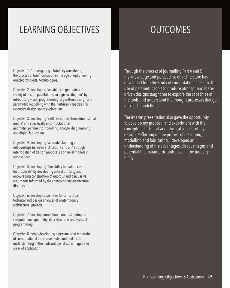
Objective 1. “interrogating a brief” by consideringthe process of brief formation in the age of optioneeringenabled by digital technologies.
Objective 2. developing “an ability to generate avariety of design possibilities for a given situation” byintroducing visual programming, algorithmic design andparametric modelling with their intrinsic capacities forextensive design-space exploration.
Objective 3. developing “skills in various three dimensionalmedia” and specifically in computationalgeometry, parametric modelling, analytic diagrammingand digital fabrication.
Objective 4. developing “an understanding ofrelationships between architecture and air” throughinterrogation of design proposal as physical models inatmosphere.
Objective 5. developing “the ability to make a casefor proposals” by developing critical thinking andencouraging construction of rigorous and persuasivearguments informed by the contemporary architecturaldiscourse.
Objective 6. develop capabilities for conceptual,technical and design analyses of contemporaryarchitectural projects.
Objective 7. develop foundational understandings ofcomputational geometry, data structures and types ofprogramming.
Objective 8. begin developing a personalized repertoireof computational techniques substantiated by theunderstanding of their advantages, disadvantages andareas of application.
Through the process of journalling Part A and B, my knowledge and perspective of architecture has developed from the study of computational design. The use of parametric tools to produce atmospheric space-driven designs taught me to explore the capacities of the tools and understand the thought processes that go into such modelling.
The interim presentation also gave the opportunity to develop my proposal and experiment with the conceptual, technical and physical aspects of my design. Reflecting on the process of designing, modelling and fabricating, I developed an understanding of the advantages, disadvantages and potential that parametric tools have in the industry today.
LEARNING OBJECTIVES OUTCOMES
B.7 Learning Objectives & Outcomes | 49
APPENDIX - ALGORITHMIC SKETCHBOOK
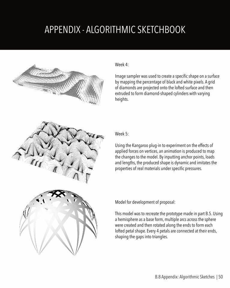
Week 4:
Image sampler was used to create a specific shape on a surface by mapping the percentage of black and white pixels. A grid of diamonds are projected onto the lofted surface and then extruded to form diamond-shaped cylinders with varying heights.
Week 5:
Using the Kangaroo plug-in to experiment on the effects of applied forces on vertices, an animation is produced to map the changes to the model. By inputting anchor points, loads and lengths, the produced shape is dynamic and imitates the properties of real materials under specific pressures.
Model for development of proposal:
This model was to recreate the prototype made in part B.5. Using a hemisphere as a base form, multiple arcs across the sphere were created and then rotated along the ends to form each lofted petal shape. Every 4 petals are connected at their ends, shaping the gaps into triangles.
B.8 Appendix: Algorithmic Sketches | 50

PART B REFERENCESFig. 1.1Iwamotoscott Architecture [2008] Voussoir Cloud < http://www.iwamotoscott.com/VOUSSOIR-CLOUD>Fig. 1.2, 1.3Achimmenges.net [2010] ICD/ITKE Research Pavilion 2010 < http://www.achimmenges.net/?p=4443>
Fig. 2.1, 2.3, 2.4Archdaily [2012] Voussoir Cloud < http://www.archdaily.com.br/br/01-54024/voussoir-cloud-iwamotoscott-architecture-mais-buro-happold>Fig. 2.2Dezeen [2008] Voussoir Cloud < http://www.dezeen.com/2008/08/08/voussoir-cloud-by-iwamotoscott/>
Fig. 3.1Digital Crafting [2010] ICD/ITKE Research Pavilion 2010 < http://www.digitalcrafting.dk/?cat=9>

PART C.
MATERIAL PERFORMANCE // STRIPS & FOLDINGS
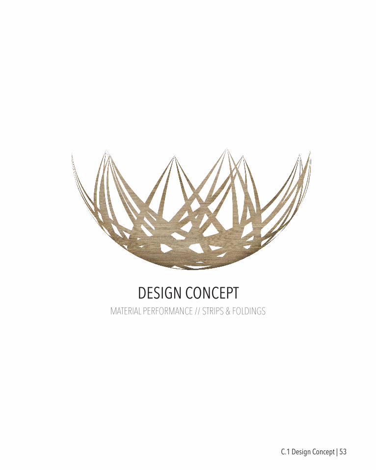
DESIGN CONCEPT
C.1 Design Concept | 53
Using our interim model as the foundation of our design, we experimented with converging strips and used a hemisphere as the base shape of the vaults on grasshopper. However, we felt that more development was needed to create a suitable yet dynamic ceiling feature for the site. Hence, we decided on multiple points we wanted to achieve and factors pointed out in the interim presentation to improve on. Changes to the design were reflected in the subsequent prototypes, refining the fabrication processes and assembly.
INTERIM FEEDBACK
1. Physical model was more interesting than the digital model
2. Thickness of strips can vary along each strip
3. Connections to join strips together can be more developed
4. Instead of looking at each vault individually, the ceiling installation can be perceived as a whole system
5. The product should be less like an “arts & crafts” project, should instead rely on parametric design to create and fabricate
CONCEPT DEVELOPMENT
1. To fully utilize the volume of the space
2. Integrate sensory effects such as shadow-play
3. To have structural integrity and constructibility
4. Develop the vault to break away from the constraints of a hemisphere
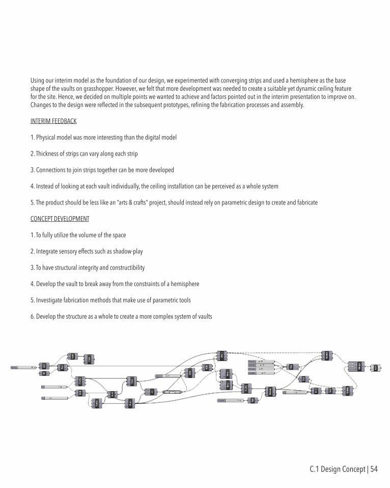
5. Investigate fabrication methods that make use of parametric tools
6. Develop the structure as a whole to create a more complex system of vaults
C.1 Design Concept | 54

As we experienced difficulties assembling individual strips into a vault, we wanted to experiment with overlaying individual petals with slits that converge at their end points, to provide a modular solution for reducing the complexity of constructing the model. We also tested different joints through 3D printing the connections between petals and each vault.
However, we noticed that the joints we made were too bulky and were not aesthetically pleasant or appropriate for the design criteria we had in mind. We also had trouble visualizing the final product as we had cut it at too small a scale and used veneer that was too rigid and easily broken.
From this prototype, we learnt that we were able to pull up and constrain points in the centre of each vault to support the structure. We also had to purchase a different type of veneer that was more suitable for curvilinear forms, and decided on paper-backed veneer that was more flexible and easier to push the limits of veneer performance to produce the undulating form we had in mind.
In our design, we aimed to have 2 core construction elements which make up the structure.
1. Strips which varied in thickness by converging at the ends
2. Non-adhesive joints that would serve dual functions of connecting vaults together and attaching the structure to the ceiling
The following prototypes display the experiments and adjustments to our first model, and the process and direction we took to achieve our final model.
PROTOTYPE ONE
TECTONICS ELEMENTS & PROTOTYPES
C.2 Tectonic Elements & Prototypes | 55
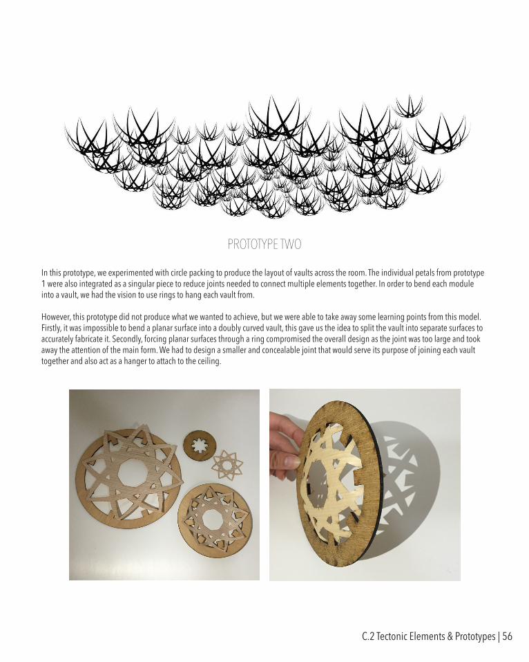
In this prototype, we experimented with circle packing to produce the layout of vaults across the room. The individual petals from prototype 1 were also integrated as a singular piece to reduce joints needed to connect multiple elements together. In order to bend each module into a vault, we had the vision to use rings to hang each vault from.
However, this prototype did not produce what we wanted to achieve, but we were able to take away some learning points from this model. Firstly, it was impossible to bend a planar surface into a doubly curved vault, this gave us the idea to split the vault into separate surfaces to accurately fabricate it. Secondly, forcing planar surfaces through a ring compromised the overall design as the joint was too large and took away the attention of the main form. We had to design a smaller and concealable joint that would serve its purpose of joining each vault together and also act as a hanger to attach to the ceiling.
PROTOTYPE TWO
C.2 Tectonic Elements & Prototypes | 56
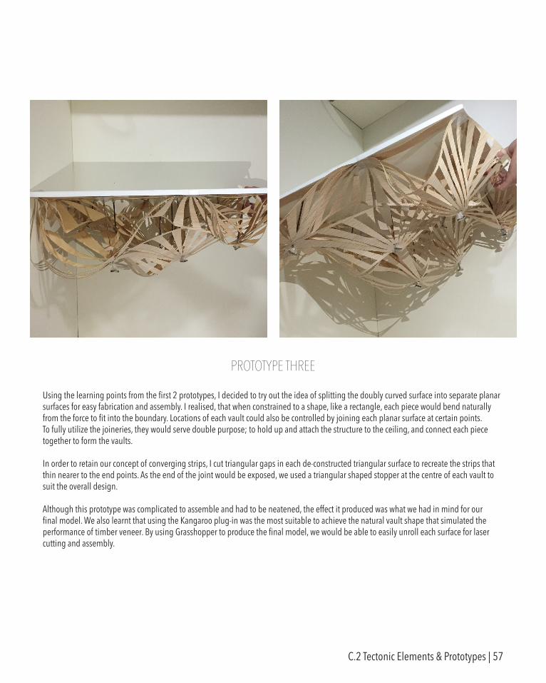
Using the learning points from the first 2 prototypes, I decided to try out the idea of splitting the doubly curved surface into separate planar surfaces for easy fabrication and assembly. I realised, that when constrained to a shape, like a rectangle, each piece would bend naturally from the force to fit into the boundary. Locations of each vault could also be controlled by joining each planar surface at certain points. To fully utilize the joineries, they would serve double purpose; to hold up and attach the structure to the ceiling, and connect each piece together to form the vaults.
In order to retain our concept of converging strips, I cut triangular gaps in each de-constructed triangular surface to recreate the strips that thin nearer to the end points. As the end of the joint would be exposed, we used a triangular shaped stopper at the centre of each vault to suit the overall design.
Although this prototype was complicated to assemble and had to be neatened, the effect it produced was what we had in mind for our final model. We also learnt that using the Kangaroo plug-in was the most suitable to achieve the natural vault shape that simulated the performance of timber veneer. By using Grasshopper to produce the final model, we would be able to easily unroll each surface for laser cutting and assembly.
PROTOTYPE THREE
C.2 Tectonic Elements & Prototypes | 57
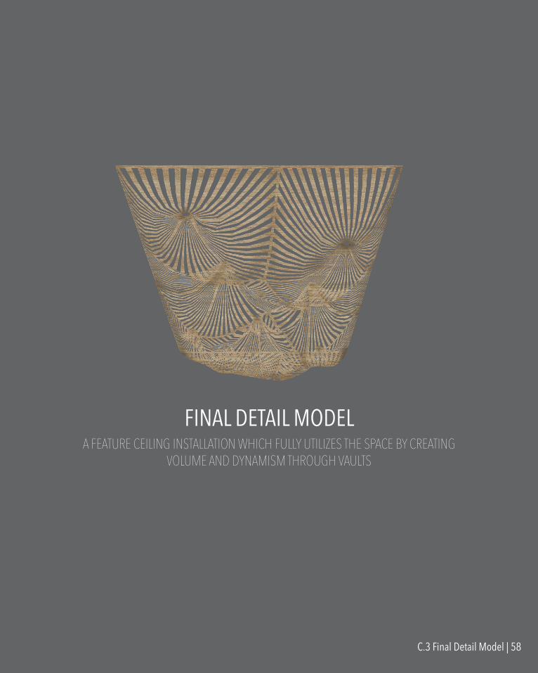
A FEATURE CEILING INSTALLATION WHICH FULLY UTILIZES THE SPACE BY CREATING VOLUME AND DYNAMISM THROUGH VAULTS
FINAL DETAIL MODEL
C.3 Final Detail Model | 58
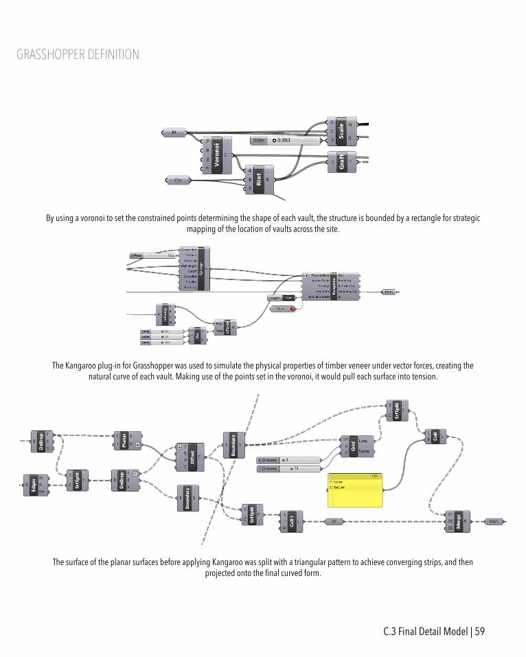
GRASSHOPPER DEFINITION
By using a voronoi to set the constrained points determining the shape of each vault, the structure is bounded by a rectangle for strategic mapping of the location of vaults across the site.
The Kangaroo plug-in for Grasshopper was used to simulate the physical properties of timber veneer under vector forces, creating the natural curve of each vault. Making use of the points set in the voronoi, it would pull each surface into tension.
The surface of the planar surfaces before applying Kangaroo was split with a triangular pattern to achieve converging strips, and then projected onto the final curved form.
C.3 Final Detail Model | 59
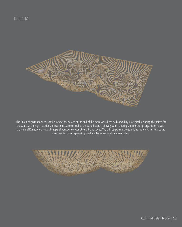
RENDERS
The final design made sure that the view of the screen at the end of the room would not be blocked by strategically placing the points for the vaults at the right locations. These points also controlled the varied depths of every vault, creating an interesting, organic form. With the help of Kangaroo, a natural shape of bent veneer was able to be achieved. The thin strips also create a light and delicate effect to the
structure, inducing appealing shadow-play when lights are integrated.
C.3 Final Detail Model | 60

PERSPECTIVES
C.3 Final Detail Model | 61
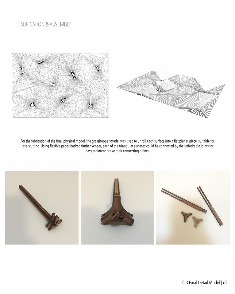
FABRICATION & ASSEMBLY
For the fabrication of the final physical model, the grasshopper model was used to unroll each surface into a flat planar piece, suitable for laser cutting. Using flexible paper-backed timber veneer, each of the triangular surfaces could be connected by the unlockable joints for
easy maintenance at their connecting points.
C.3 Final Detail Model | 62
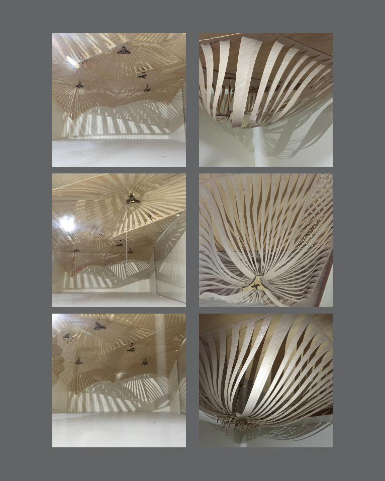
LEARNING OBJECTIVES & OUTCOMESDuring the final presentation, the feedback suggested development to the form when perceived in the 1:1 scale as there was a possibility that we had designed each module to be too large. It was also suggested to overlay multiple modules on top of one another to create a denser vault of strips. Due to the delicateness of the thin strips, thought could have been put into the method of support around the installation’s edges instead of relying solely on the presented connections.
Studio Air was an eye-opening subject which introduced parametric tools and methods that could shape designs in a way that I was never exposed to before. I was able to create and manipulate various interesting forms with self-set rules and conditions to achieve my intended design. Also benefitting from the ease of adjusting values and applying commands to refine and shape the model. This subject has ultimately taught me a new skill set which I can apply in my future.
C.4 Learning Objectives & Outcomes | 64