radiographic and computed tomographic · pdf fileradiographic and computed tomographic...
TRANSCRIPT
RADIOGRAPHIC AND COMPUTED TOMOGRAPHIC PLANNING Michael P. Kowaleski, DVM, DACVS, DECVS
Cummings School of Veterinary Medicine, Tufts University, North Grafton, MA Key Points
• The Center Of Rotation of Angulation (CORA) methodology can be used to develop breed specific, normal joint reference angles or individual joint reference angles from a normal limb
• The normal joint reference angles are used to identify the location and magnitude of a deformity
• Planning can be done on radiographic projections or three-dimensional volumetric reconstruction of computed tomographic (CT) images Angular limb deformity correction and limb alignment to correct skeletal malalignment
are commonly employed in small animal orthopedic surgery. Until recently, a unified system that was applicable to all deformities in all long bones was lacking in veterinary surgery. Recently, the Center of Rotation of Angulation (CORA) methodology has been described for use in deformity planning and correction in people, and several authors have adapted this system for use in dogs. The CORA methodology utilized an axis drawn along the long bone and two joint reference lines drawn across the joint at specific anatomic landmarks to develop reference angles for the proximal and distal joint of each long bone. Two axes exist in each bone; the anatomic axis is drawn from the center of proximal end of the bone to the center of its distal end, while the mechanical axis is drawn from the center of the proximal joint to the center of the distal joint. In bones such as the femur the mechanical and anatomic axes are different, while in other bones, such as the tibia, the axes are identical. The intersection between the joint reference line and the bone axis determine the joint reference angle.
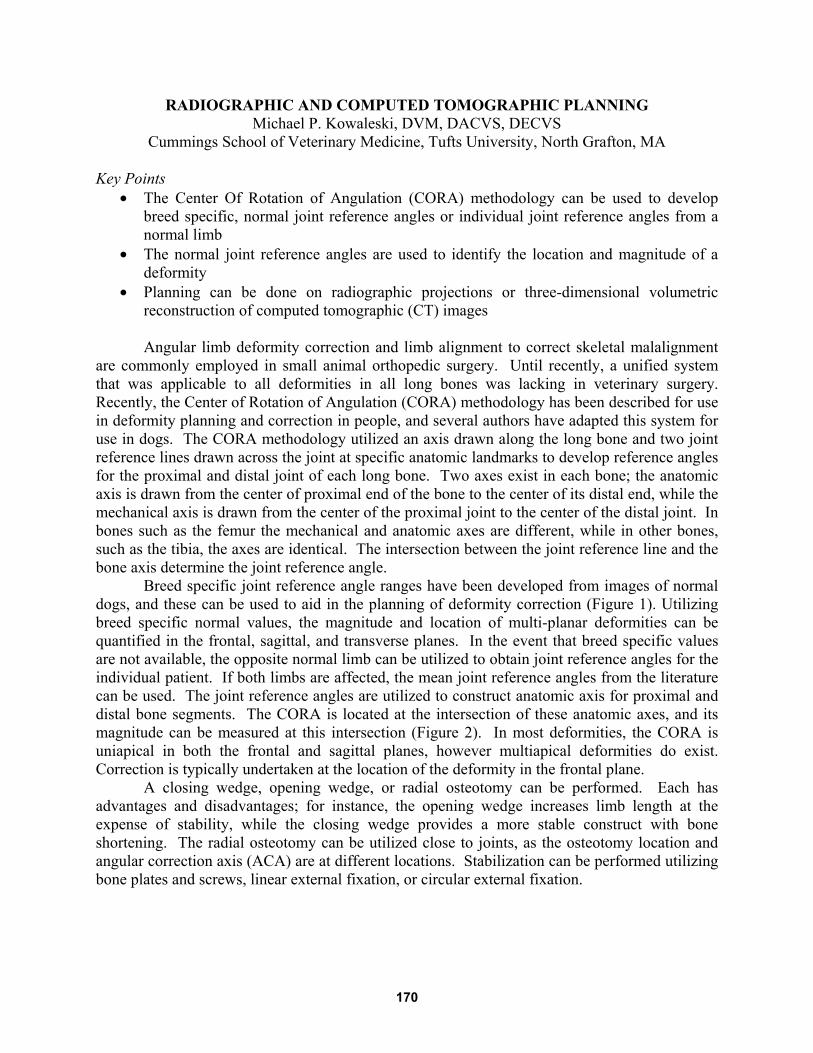
Breed specific joint reference angle ranges have been developed from images of normal dogs, and these can be used to aid in the planning of deformity correction (Figure 1). Utilizing breed specific normal values, the magnitude and location of multi-planar deformities can be quantified in the frontal, sagittal, and transverse planes. In the event that breed specific values are not available, the opposite normal limb can be utilized to obtain joint reference angles for the individual patient. If both limbs are affected, the mean joint reference angles from the literature can be used. The joint reference angles are utilized to construct anatomic axis for proximal and distal bone segments. The CORA is located at the intersection of these anatomic axes, and its magnitude can be measured at this intersection (Figure 2). In most deformities, the CORA is uniapical in both the frontal and sagittal planes, however multiapical deformities do exist. Correction is typically undertaken at the location of the deformity in the frontal plane.
A closing wedge, opening wedge, or radial osteotomy can be performed. Each has advantages and disadvantages; for instance, the opening wedge increases limb length at the expense of stability, while the closing wedge provides a more stable construct with bone shortening. The radial osteotomy can be utilized close to joints, as the osteotomy location and angular correction axis (ACA) are at different locations. Stabilization can be performed utilizing bone plates and screws, linear external fixation, or circular external fixation.
170
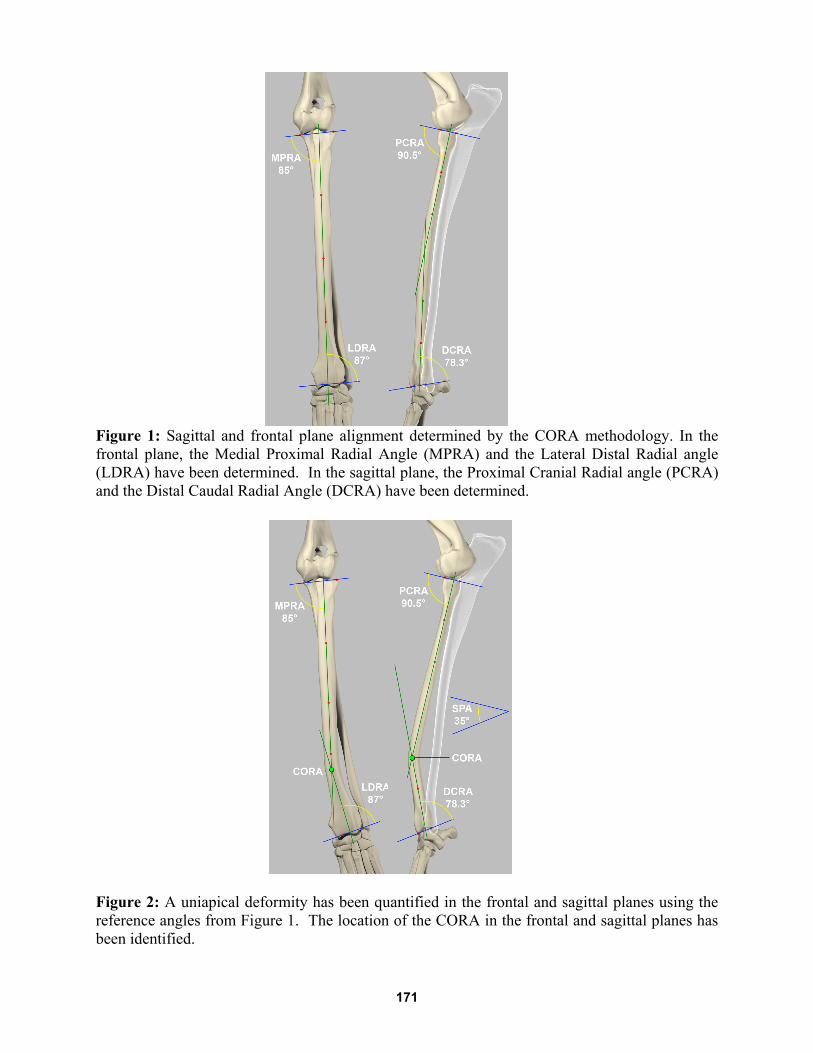
Figure 1: Sagittal and frontal plane alignment determined by the CORA methodology. In the frontal plane, the Medial Proximal Radial Angle (MPRA) and the Lateral Distal Radial angle (LDRA) have been determined. In the sagittal plane, the Proximal Cranial Radial angle (PCRA) and the Distal Caudal Radial Angle (DCRA) have been determined.
Figure 2: A uniapical deformity has been quantified in the frontal and sagittal planes using the reference angles from Figure 1. The location of the CORA in the frontal and sagittal planes has been identified.
171
Radiographic and Computed Tomographic Planning for Distal Femoral Corrective Osteotomy Accurate radiographic assessment of limb alignment is difficult, and requires heavy
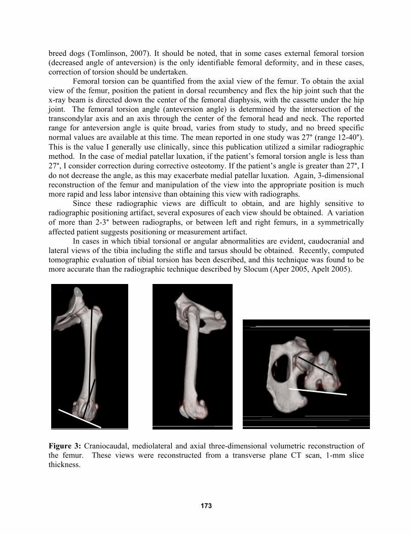
sedation or general anesthesia and precise patient positioning to avoid positioning artifact. A complete radiographic evaluation includes at least craniocaudal and mediolateral views of the femur and proximal tibia, and an axial view of the femur for femoral torsion determination. In some cases caudocranial and mediolateral views of the tibia including the stifle and tarsus may be required. Alternatively, a computed tomographic method with analysis of individual slices (Dudley 2006) or 3-dimensional volumetric reconstruction with manipulation of the volume to represent views analogous to the radiographic images can be utilized (Figure 3).
A well-positioned craniocaudal view of the femur and proximal tibia is the radiographic view that is used to screen for and quantify femoral varus deformity. It is imperative that the femur is parallel and the radiographic beam perpendicular to the radiographic cassette or detector. In cases in which diminished hip range of motion limits hip extension, the x-ray beam and cassette or detector can be angled such that the x-ray beam is perpendicular to the long axis of the femur, and the cassette or detector is perpendicular to the beam. Alternatively, the patient can be elevated in a V-trough, or a horizontal beam, craniocaudal femur can be obtained. In a well-positioned view, the fabellae appear bisected by the femoral cortices, the vertical walls of the intercondylar notch are distinct parallel lines, and the lesser trochanter is only partially visible; often the proximal femoral nutrient foramen can be identified as a small, round lucency centered between the femoral cortices in the proximal diaphysis.
The benefit of 3-dimensional volumetric reconstruction of CT images is that the image (volume) can be rapidly manipulated into the appropriate position to simulate the radiographic views. In a normal femur, the magnitude of femoral varus (or valgus) is determined by measuring the anatomic lateral distal femoral angle (aLDFA) at the intersection of the femoral anatomic axis and the distal joint reference line of the femur, using the radiographic method described by Tomlinson (Tomlinson 2007) or the computed tomographic method described by Dudley (Dudley 2006) or 3-dimensional reconstruction can be employed (Figure 3). In a femur with pathologic femoral varus or valgus, the femoral deformity is determined at the center of angulation of rotation (CORA) located at the intersection of the proximal and distal anatomical axes of the femur.
In the radiographic and CT methods, the overall length of the femur is determined, and the center of the femur at 33% and 50% of its length is identified. A line is drawn connecting these two points; this is the anatomic axis of the femur. The distal joint reference line is a line connecting the most distal aspect of the medial and lateral condyles of the femur. The aLDFA is measured at the intersection of the anatomic axis and the distal joint reference line. Comparison of the aLDFA to a breed specific reference range will determine if significant femoral varus is present. If a significant femoral varus deformity is present, the location and magnitude of the deformity must be determined. Measure the overall length of the femur, and identifying the center of the femur at 33% and 50% of its length, draw a line connecting these two points to determine the proximal femoral anatomic axis; in this case, the line is not drawn to the joint level. Draw the distal joint reference line, set the aLDFA to the breed specific value, and draw the distal anatomic axis such that the line extends along the lateral aspect of the intercondylar notch. The CORA is located at the intersection of the proximal and distal anatomic axes, and its magnitude can be measured at this location. If a breed specific normal value is not available, then the opposite normal femur can be measured as a reference. If the opposite femur is affected, the aLDFA can be arbitrarily set to 94-98°, as this is the value for a number of large
172
breed dogs (Tomlinson, 2007). It should be noted, that in some cases external femoral torsion (decreased angle of anteversion) is the only identifiable femoral deformity, and in these cases, correction of torsion should be undertaken.
Femoral torsion can be quantified from the axial view of the femur. To obtain the axial view of the femur, position the patient in dorsal recumbency and flex the hip joint such that the x-ray beam is directed down the center of the femoral diaphysis, with the cassette under the hip joint. The femoral torsion angle (anteversion angle) is determined by the intersection of the transcondylar axis and an axis through the center of the femoral head and neck. The reported range for anteversion angle is quite broad, varies from study to study, and no breed specific normal values are available at this time. The mean reported in one study was 27° (range 12-40°). This is the value I generally use clinically, since this publication utilized a similar radiographic method. In the case of medial patellar luxation, if the patient’s femoral torsion angle is less than 27°, I consider correction during corrective osteotomy. If the patient’s angle is greater than 27°, I do not decrease the angle, as this may exacerbate medial patellar luxation. Again, 3-dimensional reconstruction of the femur and manipulation of the view into the appropriate position is much more rapid and less labor intensive than obtaining this view with radiographs.
Since these radiographic views are difficult to obtain, and are highly sensitive to radiographic positioning artifact, several exposures of each view should be obtained. A variation of more than 2-3° between radiographs, or between left and right femurs, in a symmetrically affected patient suggests positioning or measurement artifact. In cases in which tibial torsional or angular abnormalities are evident, caudocranial and lateral views of the tibia including the stifle and tarsus should be obtained. Recently, computed tomographic evaluation of tibial torsion has been described, and this technique was found to be more accurate than the radiographic technique described by Slocum (Aper 2005, Apelt 2005).
Figure 3: Craniocaudal, mediolateral and axial three-dimensional volumetric reconstruction of the femur. These views were reconstructed from a transverse plane CT scan, 1-mm slice thickness.
173
Apelt D, Kowaleski MP, Dyce J: Comparison of computed tomographic and standard radiographic determination of tibial torsion in the dog. Vet Surg 2005;34:457-462 Aper R, Kowaleski MP, Apelt D, et al: Computed tomographic determination of tibial torsion in the dog, Vet Radiol Ultrasound 2005;46:187-191 Dismukes DI, Tomlinson, JL Fox DB, et al: Radiographic Measurement of the Proximal and Distal Mechanical Joint Angles in Canine Tibia, Vet Surg 2007;36:699-704 Dismukes DI, Fox DB, Tomlinson JL, et al: Determination of Pelvic Limb Alignment in the Large-Breed Dog: A Cadaveric Radiographic Study in the Frontal Plane. Vet Surg 2008;37:674-682 Dudley RM, Kowaleski MP, Drost WT, et al: Radiographic and computed tomographic determination of femoral varus and torsion in the dog, Vet Radiol Ultrasound 2006;47:546-552 Fox DB, Tomlinson JL, Cook JL, et al : Principles of Uniapical and Biapical Radial Deformity Correction Using Dome Osteotomies and the Center of Rotation of Angulation Methodology in Dogs, Vet Surg 2006;35:67-77 Paley D: Principles of Deformity Correction. (ed: Hirzenberg JE). Springer-Verlag, Berlin 2003 Tomlinson JL; Fox DB, Cook JL, et al: Measurement of Femoral Angles in Four Dog Breeds, Vet Surg 2007;36:593-598
174