computed tomographic anatomy of the temporal bone · 2014-03-27 · computed tomographic anatomy of...
TRANSCRIPT
Chat Virapongse 1
Stephen L. G. Rothman E. Leon Kier
Mahammad Sarwar
This article appears in the July / August 1982 issue of AJNR and the October 1982 issue of AJR.
Received March 9, 1981; accepted after revision January 6, 1982.
Presented at the annual meeting of the American Society of Neuroradiology, Chicago, April 1981 .
'All authors: Department of Diagnosti c Radiology, Section of Neuroradiology, Yale Universi ty School of Medicine, 333 Cedar St., New Haven , CT 06510. Address reprint requests to C. Virapongse.
AJNR 3:379-389, July / August 1982 0195-6108/ 82 / 0304- 0379 $00.00 © American Roentgen Ray Society
Computed Tomographic Anatomy of the Temporal Bone
379
With the recent development of high-resolution computed tomography (CT), there is a growing need to explore the full potential of this new method in demonstrating the detailed anatomy of the temporal bone. For this purpose, dry skulls with intact ossicles were scanned in axial and coronal projections. The detailed CT anatomy of t he temporal bone was documented, complemented by images from live patients. Because of its superior contrast resolution , CT was able to demonstrate numerous structures, such as the tympanic membrane, ossicies , and supporting structures, hitherto never or poorly visualized by any other method. In addition , the ease by which axial sections of the temporal bone could be obtained is of great benefit in displaying several structures previously difficult to evaluate.
Computed tomographic (CT) scanning has proven to be indispensable in the evaluation of intracranial pathology, but its role in the evaluation of the temporal bone anatomy and pathology has not been fully exp lored [1]. Recent improvements in CT scanners have made availab le detailed information of the temporal bone [2], and certain structures that were previously poorly visib le by other methods are now c learly seen [1 -6]. The wealth of anatom ic data displayed in vari ous projections on CT poses a diagnosti c challenge to neuroradiologists and clinicians. Furthermore, the understanding of the CT anatomy of the temporal bone is difficult due to complex structural re lations that cannot be visualized on a single plane [7]. Our systematic CT analysis of the temporal bone was undertaken to demonstrate and document this detailed anatomy.
Materials and Methods
All scans were obtained with a Pf izer 0200FS scanner in a " neuropack " configuration. The scanner contains a detector array of 30 calc ium fluoride c rystals, each 2.5 x 3. 5 mm . The detectors are collimated so that on ly the central 1 .5 x 1.5 mm are open to th e x-ray beam. The x-ray beam width is narrowed to 2 mm by a manual slide, and the slice thickn ess is collimated to 2 mm by a removable stainless steel tube-side collimator.
The scanning algorithm is modified by increasing the sampling rate by a factor of two and by decreasing the translation arm speed to about 40 sec. The combination of these two software mod ifications and decreasing the detector size improves the geometric resolution allowing visualization of 0.75 mm pins in the American Association of Physicists in Medicine phantom. Th e image is then back-projected onto 0.3 mm pixe ls and recorded in the usual manner.
Hounsfield [8] suggested that scans of the bones of the middle ear wou ld not be degraded by graininess at p ixel sizes greater than 0 .25 mm. We have successfull y backprojected the epithympanum into 0 .15 mm pi xels, but suggest that, unless the sampling rate would again be halved , 0 .3 mm pixels seem a better compromise. Because of the small pixel size, the zone of reconstruction is constric ted to only 200 c m2
.
It is possible to reconstruct only one temporal bone at a time, although both are scanned simu ltaneously. This disadvantage is c ircumvented by storing th e raw data on d isk and recomputing the opposite temporal bone from th is data at the completion of the study. If it
380 VIRAPONGSE ET AL. AJNR:3 , July / August 1982
is cruc ial to see both temporal bones at the time the scans are obtained, it is possible to back-project the scan onto 0.5 mm pixels and display a rectangular area of reconstruct ion aligned to encompass both temporal bones. The reso lution in this scanning mode is not as good as in the 0.3-mm-pixel scan, but if the data are stored on disk or magnetic tape, the two temporal bones can be recomputed with 0 .3 mm pixels at the termination of th e examinat ion.
More than 80 unprepared dry skull s were examined in an attempt to find skull s with intact ossicular chains. Ossic les are absent in commerc ially available skulls as th e result of destruction of the ligaments, tendons, and the tympanic membrane during the preparation process. In vivo, these soft-ti ssue structures form the natural support of the ossic les, tethering them to each wall of the middle ear cavity. It is not uncommon to find an intact ossicu lar c hain either in one or both ears in a newborn prepared skull , since often the tympanic membrane is left intac t, provid ing the ossic les with their lateral support. In the adult skull , as a rule, the ossic les are absent. Most of the dry skulls examined had lost their tympanic membranes and ossic les.
Dry skulls were scanned in the ax ial and coronal planes. Two techniques were considered and compared. A " low" kilovoltage technique using 80 kV and 50 mA and a " high " ki lovoltage technique using 140 kV and 35 mA were performed on each skull. The latter technique offered the best detai l, and all the CT scans in this study, inc luding scans of c linica l subjects, were performed in this manner. All scans were obtained at 40 sec.
Forty-five patients were scanned. In most, only th e axial projection was used, primarily due to the ease of patient positioning and patient comfort. Th e coronal projection was attempted in some, but occasionally resulted in a poor image due to patient motion . At the termin ation of the stud y, reconstruction of the opposite ear was performed .
The illustrations in our anatomic study are a combination of those provided from dry skulls and those from our normal c linical subjects. The individual images were chosen to display d iscrete anatomic structures, some of wh ich are best displayed in the dry skull , while oth ers require delineat ion of soft tissue best demonstrated in live pat ients.
Observations and Discussion
Our observations are divided into sections based on each major part of the ear and also on arbitrary grouping of a set of structures of special interest. Each section contains an anatomic description fo llowed by observations and comments, so that each set of anatomic structures is dealt with sequentially in its entirety .
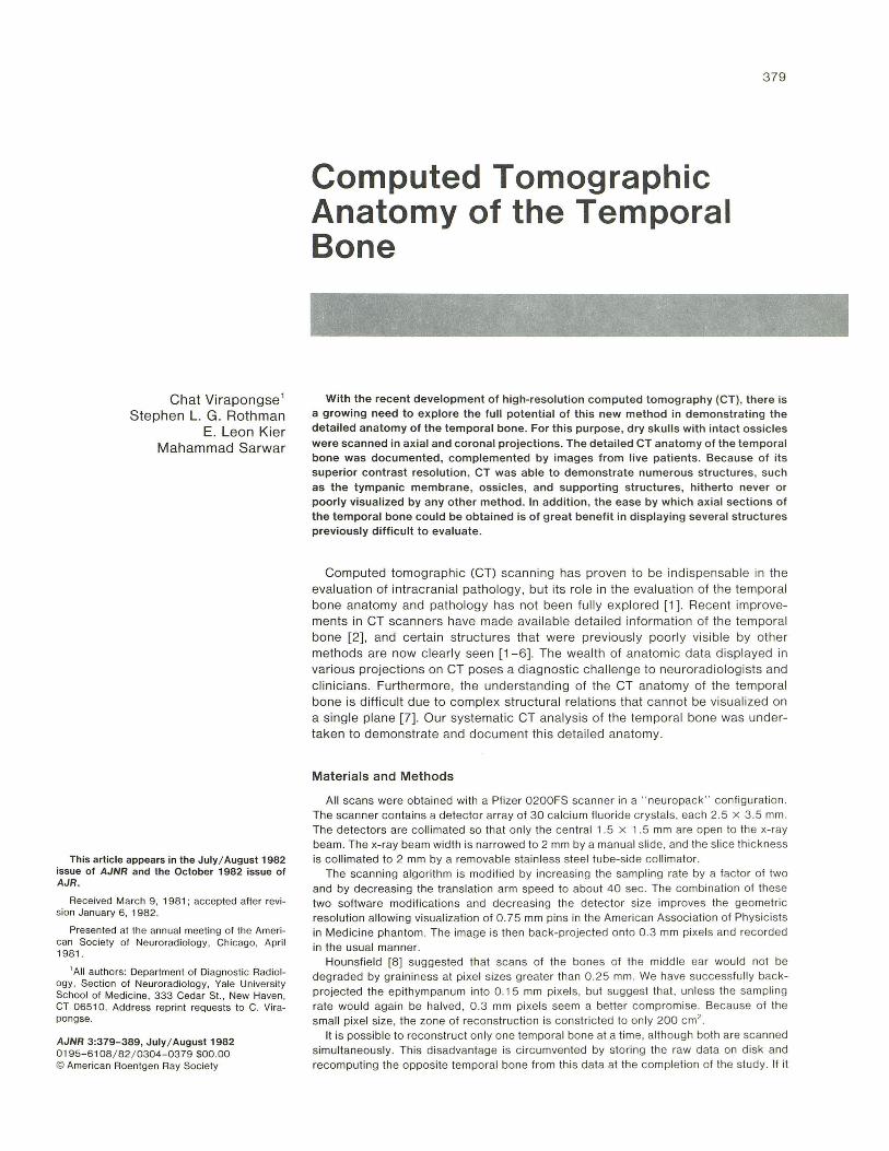
H--~4-~~~~~~--7T~~~~~~---G--~------------~~
i~~~~~~~~~~!1~~~:i~~~~~~~ ~====~~==~==~~~~~=======
A
Ex ternal Auditory Canal
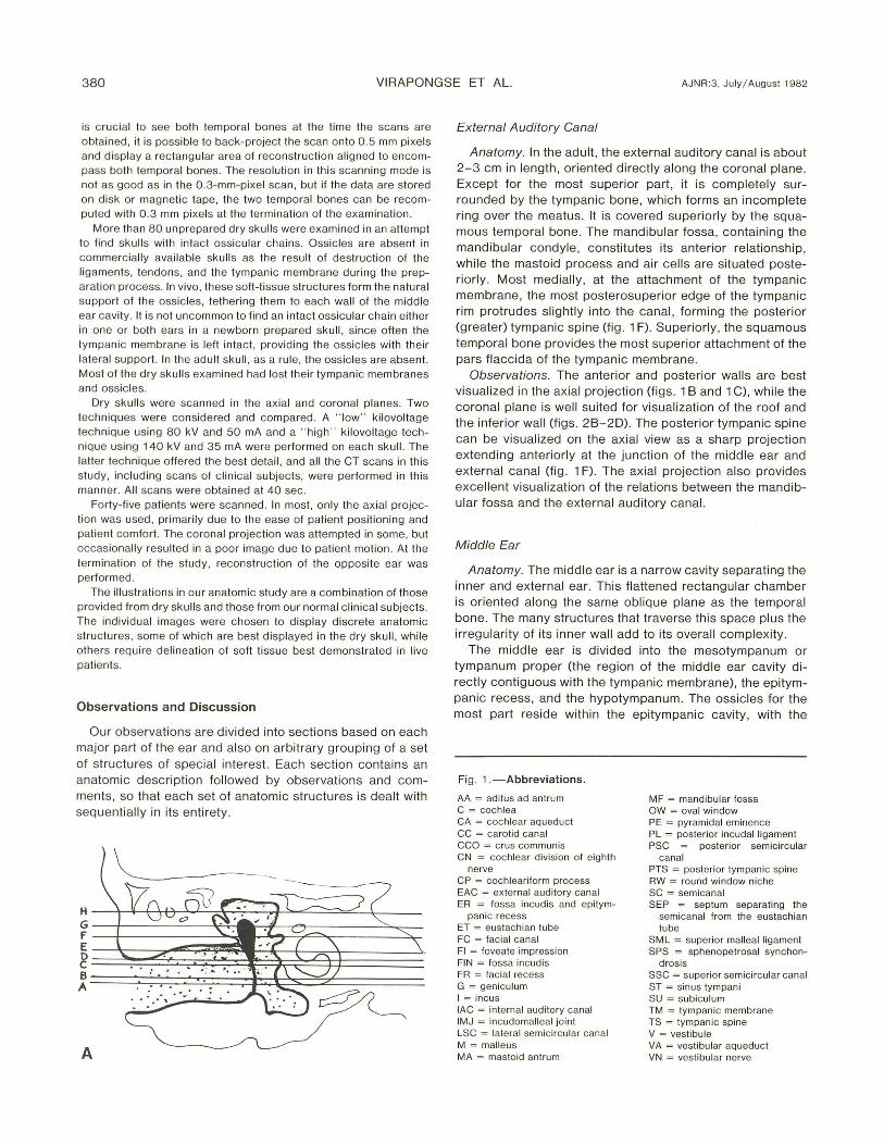
Anatomy. In the adult, the external auditory canal is about 2-3 cm in length, oriented directly along the coronal plane. Except for the most superior part, it is completely surrounded by the tympanic bone, which forms an incomplete ring over the meatus. It is covered superiorly by the squamous temporal bone. The mandibular fossa, contain ing the mandibular condyle, constitutes its anterior relationship , while the mastoid process and air ce lls are situated posteriorly. Most medially, at the attachment of the tympanic membrane, the most posterosuperior edge of the tympan ic rim protrudes slightly into the canal, forming the posterior (greater) tympanic spine (fig. 1 F) . Superiorly, the squamous temporal bone provides the most superior attachment of the pars flaccida of the tympanic membrane.
Observations. The anterior and posterior walls are best visualized in the axial projection (figs. 18 and 1 C), while the corona l plane is well suited for visualization of the roof and the inferior wall (figs . 28-20). The posterior tympanic spine can be visualized on the axial view as a sharp projection extending anteriorly at the junction of the middle ear and external canal (fig . 1 F). The axial projection also provides excellent visualization of the relations between the mandibular fossa and the external aud itory canal.
Middle Ear
Anatomy. The middle ear is a narrow cavity separating the inner and external ear. This flattened rectangular chamber is oriented along the same oblique plane as the temporal bone. The many structures that traverse this space plus the irregularity of its inner wall add to its overall complexity.
The middle ear is divided into the mesotympanum or tympanum proper (the region of the middle ear cavity directly contig uous with the tympanic membrane), the epitympanic recess , and the hypotympanum. The ossicles for the most part reside within the epitympanic cavity, with the
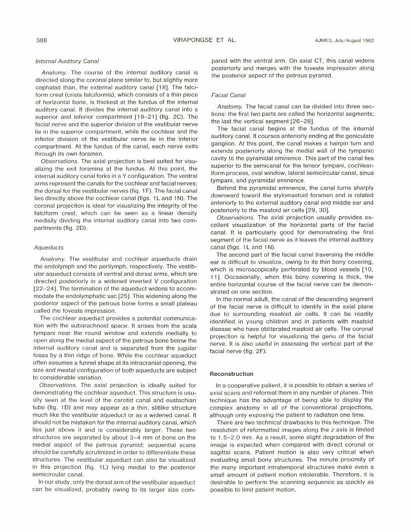
Fig . 1.-Abbreviations.
AA = ad itus ad anlrum C = cochlea CA = cochlear aqueduct CC = carot id canal CCO = crus communis CN = cochlear division of eighth
nerve CP = cochleariform process EAC = ex ternal auditory canal ER = fossa incudis and epitym-
panic recess ET = eustachian tube FC = fac ial canal FI = foveate impression FIN = fossa incudis FR = facial recess G = geniculum I = incus lAC = intern al aud itory canal IMJ = incudomalleal jo int LSC = lateral semici rcular canal M = malleus MA = mastoid antrum
MF = mandibular fossa OW = oval window PE = pyramidal eminence PL = posterior incudalligament PSC = posterior semicircu lar
canal PTS = posterior tympanic spine RW = round window niche SC = semicanal SEP = septum separating the
semicanal from the eustachian tube
SM L = superior malleal ligament SPS = sphenopetrosal synchon-
drosis SSC = superi or semicircular canal ST = sinus tympani SU = subicu lum TM = tympanic membrane TS = tympanic spine V = vestibule VA = vestibular aqueduct VN = vestibu lar nerve
AJNR: 3, July / August 1982 CT OF TEMPORAL BONE 381
B
F Fig. 1 .-A-G. A, Coronal section of right temporal bone shows levels of
ax ial views in B-O. Level A is most inferior. (Fig . 4 provides a more complete anatomiC representation .) B and C, Leve l A, live patient, passing through basal turn of cochlea. Trefoil appearance formed by round window niche, sinus tympani , and facia l recess. Air-filled bony part o f eustach ian tube is directed anterom edially parallel to carotid canal. 0 and E, Level B, live
c
E
G
ElJSTACH IIW 1UFE
STPffS& [Nfl!. WINIXlI
CPW\L Fffi COCHlEAR
~-----DIVISI~ (f
STPffDlfl!. TEIID1
8lll NEJM:
patient, also passes through basal turn of cochlea. Depressions along posterior aspect of tympanic cavity not as rounded as in B, but appear more fl attened and shallow. F and G, Level C, live patient. passes through ossicular processes and ova l window. V-shaped lucency formed by internal audi tory canal and canals for two divisions of eighth nerve. Oval window appears as breach in continuity of otic capsule.
382 VIRAPONGSE ET AL. AJNR:3, July / Augusl 1 982
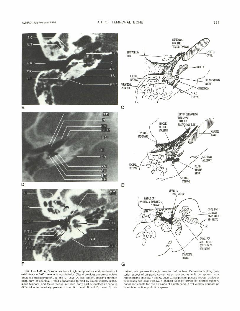
H
J
L
Fig . 1.-H-M. H and I, Through level D, juvenile temporal bone in live palient. Tensor tympanic and stapedial tendons arise from cochleariform and pyramidal processes, respectively . J and K, Through level E, dry skull , slightly above oval window , passing through ossicular processes and vestibule. L and M, Level F, live pati ent, passes through semicircular canal and
UKi PmSS (f
lNeLS
K
M
I'ASTOID AIR CElli)
COCHlEARIFatI
'i£STlBlll
facial canal. Circular lucency in petrous bone formed by lateral semic ircular canal posterolatera!ly. Vestibule and c rus communis anteromedially. Facial nerve passes anterolaterally dorsal to basal turn o f cochlea and turns sharply posteriorly at genu .
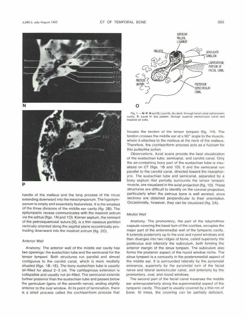
AJNR :3, July / August 1982 CT OF TEMPORAL BONE 383
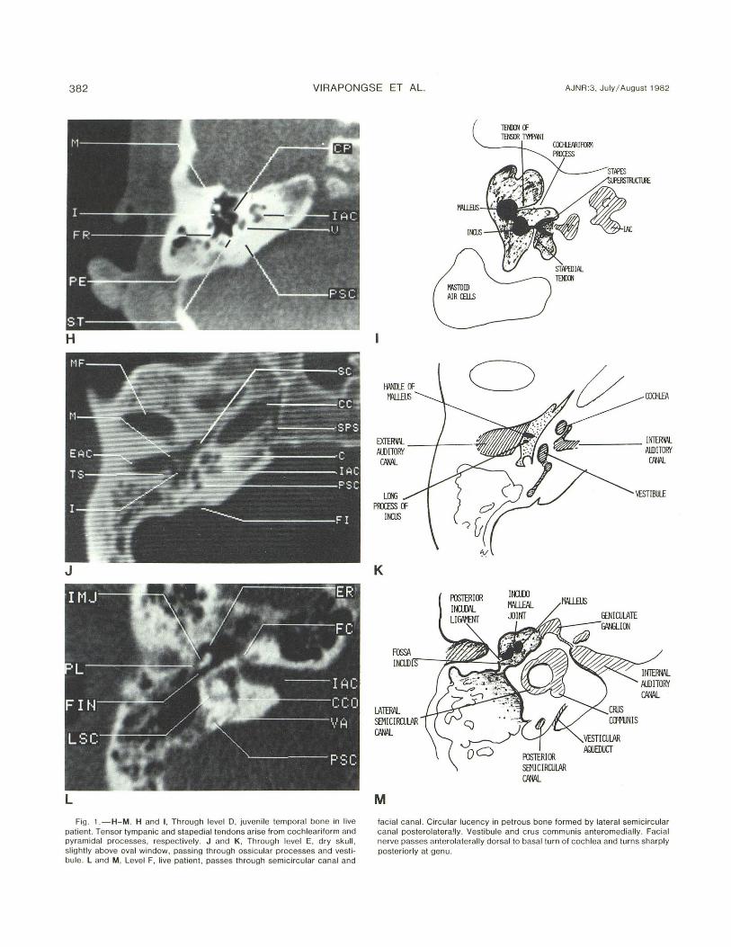
N
p
handle of the malleus and the long process of the incus extending downward into the mesotympanum. The hypotympanum is empty and essentially featureless. It is the smallest of the three divisions of the middle ear cavity (fig . 2B). The epitympanic recess communicates with the mastoid antrum via the aditus (figs. 1 Nand 10). Korner septum, the remnant of the petrosquamosal suture [9], is a thin osseous partition vertically oriented along the sagittal plane eccentrically protruding downward into the mastoid antrum (fig . 2C).
Anterior Wall
Anatomy. The anterior wall of the midd le ear cavity has two openings : the eustachian tube and the semicanal for the tensor tympani. Both structures run paralle l and almost contiguous to the carotid canal , which is more medially situated (figs . 1 B-1 E). The bony eustachian tube is usually air-filled for about 2- 3 cm. The cartil ag inous extension is co llapsible and usually not air-filled. The semicanal extends further posterior than the eustachian tube and passes below the geniculum (genu of the seventh nerve), ending slightly anterior to the oval window. At its point of termination , there is a small process called the cochleariform process that
o
SUPERIOR W\U.EAL LI~
~~;:;::;::-_ lABYRUIllH~ .J/hf // /::{<IITi'T I II FOOT I 00 (f
FACIAL CPW\L
Fig . 1 .-N-P. Nand 0 , Level G, dry skull , through facial canal epitympanic cavity . P, Level H, live patient , th rough superior semic ircular canal and mastoid air ce lls.
houses the tendon of the tensor tympani (fig . 1 H). The tendon crosses the middle ear at a 90° angle to the musc le, where it attaches to the malleus at the neck of the malleus. Therefore, the cochleariform process acts as a fulcrum for thi s pulleylike action .
Observations. Axial scans provide the best visualization of the eustachian tube, semicanal, and carotid canal. On ly the air-containing bony part of the eustachian tube is visualized on CT (figs. 1 B and 1 D) . It and the semicanal run parallel to the carotid canal, d irected toward the nasopharyn x. The eustachian tube and semicanal, separated by a bony septum that partially surrounds the tensor tympani muscle, are visualized in the axial projection (fig. 1 D). These structures are difficult to identify on the coronal projection , particularly when the petrous bone is well aerated , since sections are obtained perpendicular to their orientation. OccaSionally, however, they can be visualized (fig. 2A).
Medial Wall
Anatomy. The promontory, the part of the labyrinthine capsule covering the basal turn of the coch lea, occupies the major part of the anteromedial wall of the tympan ic cavity . It extends posteriorly up to the oval and round windows and then diverges into two ridges of bone, called superiorly the ponticulus and inferiorly the subiculum, both forming the anterior margin of the sinus tympani. The subiculum also forms the posterior aspect of the round window niche. The sinus tympani is a concavity in the posteromedial aspect of the middle ear. It is surrounded laterally by the pyramidal eminence, superiorly by the pyramidal turn of the facia l nerve and lateral semicircular canal, and anteriorly by the promontory, oval, and round windows.
The second part of the facial canal traverses the midd le ear anteroposteriorly along the superomedial aspect of the tympanic cavity. This part is usually covered by a thin rim of bone. At times , the coverin g can be partiall y defic ient,
384 VIRAPONGSE ET AL. AJNR:3, July/ August 1982
particu larly near the oval window and cochleariform process [10, 11]. The oval and round windows are located posteriorly along the medial wall. The oval window is superior and slightly ventra l to the round window, where a deep depression can be seen representing the coch lear fossula (niche) . The oval window communicates with the scala vestibuli, whil e the round window with the scala tympani; both are compartments of the perilymphatic system surrounding the membranous labyrinth.
Observations. The axial plane provides good visualization of the promontory , fossular cochlea (round window), and the subiculum (figs. 1 B and 10). The round window niche can be recognized as a sharp, deep, bony depression dorsal to the basal turn of the coch lea. The ridge of bone separating the round window from the sinus tympani is the subiculum (figs. 1 B and 10). The structures of the posteromedial wall of the tympanic cavity are best seen in this projection. The oval window is the only exception. This ovoid dehiscence, longer in its anteroposterior dimension than superoinferior dimension (2 .99 mm versus 1.41 [12]) , is difficult to visualize on the axial projection owing to partial volume effect, the slice thi ckness being 2 mm. When seen, it appears as a breach in continuity of the otic capsu le lateral to the vestibule, the stapedia l superstructure within the middle ear overlying this dehiscence more laterally (figs. 1 F and 1 G). It is eas ily seen, however , on direct coronal projection (fig. 20).
Posterior Wall
Anatomy. The posterior wall of the middle ear cavity is a complicated structure consisting of several ridges and depressions. Inferiorly, the middle ear cavity appears to extend into the mastoid and labyrinthine capsu le in a trefoil pattern of bony depression. The most medial one is the round window niche, the middle is the sinus tympani , and the most lateral is the fac ial recess (figs. 1 Band 1 0). The round window niche is separated from the sinus tympani by the subiculum , and the sinus tympani is separated from the facial recess by the pyramidal eminence . The pyramidal eminence contains the stapedius muscle and projects into the middle ear cavity in an anterosuperior direction toward the stapedial head in a beaklike manner. The pyramidal eminence is a ridge of bone, extending in an anterosuperior direction along the posterior wall , which partially hides the tympanic sinus (fig . 3). The facial nerve penetrates the posterior wall of the middle ear above and slightly lateral to the pyramidal eminence and turns 90 ° (pyramidal turn) to descend verti call y, toward the stylomastoid foramen.
Observations. The ax ial projection is ideal for the visualization of the sinus tympani and the facial recess. The ease with which the sinus tympani can be demonstrated on the ax ial projection has important c linical relevance, since this structure is difficu lt to visualize on c linical examination, being partially hidden from view by the more lateral pyramidal em inence (fig . 1 H). The size and configuration of these recesses, however, are subject to individual variat ion from rounded deep recesses to more flattened shallow ones (figs. 1 B and 10). This is also true for the pyramidal eminence,
which may not assu me a pointed triangular configuration but may be blunt and broad.
Lateral Wall
Anatomy. The lateral wall is covered to a large extent by the tympanic membrane (fig. 4) . The scutum (drum spu r), which forms the lateral wall of the epitympanic recess , projects downward for the attachment to the tympanic membrane at the tympanic incisura.
Observations . The coronal and axial views are suited for visualizing the lateral wall. The scutum is best seen in coronal section (fig. 2B).
.rioof and Floor
Anatomy. The tegmen tympani forms a thin bony roof separating the epitympanic recess from the temporal lobe. It extends posteriorly to cover the aditus and the mastoid antrum , where it is called the tegmen mastoideum. The floor of the middle ear also consists of a thin bony shell, which separates the major vessels from the middle ear cavity. The carotid artery and the jugular vein are separated most inferiorly by the caroticojugular spine, which has the appearance of an inverted triangular structure wedged between these two major vessels [9].
Observations. The coronal projection is best for demonstrating Korner septum and the tegmen tympani (fig. 2C). The thickness of the osseous floor and the hypotympanum and its relationship to the major blood vessels are best assessed on this view (fig. 20).
The caroticojugular spine can be demonstrated on axial CT as an area of bone separating the carotid canal from the jugular bulb on a low section through the temporal bone. Korner septum, the tegmen tympani, and mastoideum are difficult to identify on this projection.
Ossicles, Tendons, and Ligaments
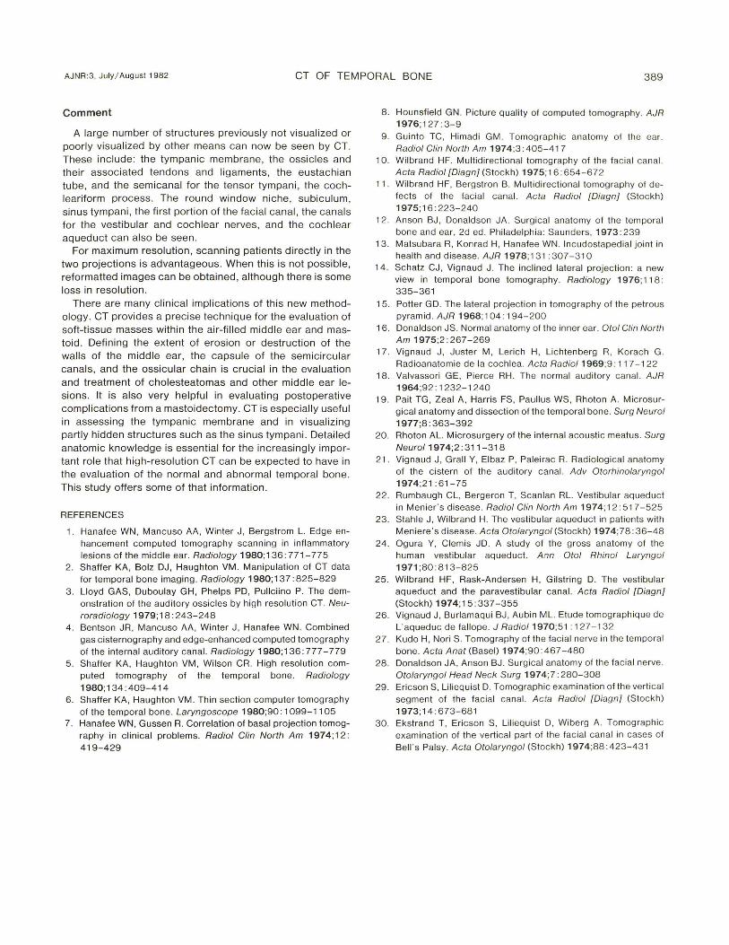
Anatomy. The auditory ossicles provide a lever mechanism for the transfer of sound energy. The malleus, incus, and stapes form a chain from the tympanic membrane to
Fig . 2.-Abbreviations.
C = cochlea CC = carot id canal CCO = crus communis CF = cri sta falciformis EAC = external auditory canal ET = eustachian lube FC = facial canal HC = hypoglossal canal HT = hypotympanum I = incus lAC = internal auditory canal JF = iugular fossa JT = jugular tubercle KS = Korner Septum LSC = lateral semicircular canal M = malleus MA = mastoid antrum
MH = malleus handle MP = mastoid process OC = occipital condyle OW = oval window P = promontory PE = pyramidal eminence PSC = posterior semicircular
canal SC = semicanal SCU = scutum SMF = stylomastoid foramen SPS = sphenopetrosal synchon-
drosis SSC = superior semicircular canal TT = tegmen tympani V = vestibule
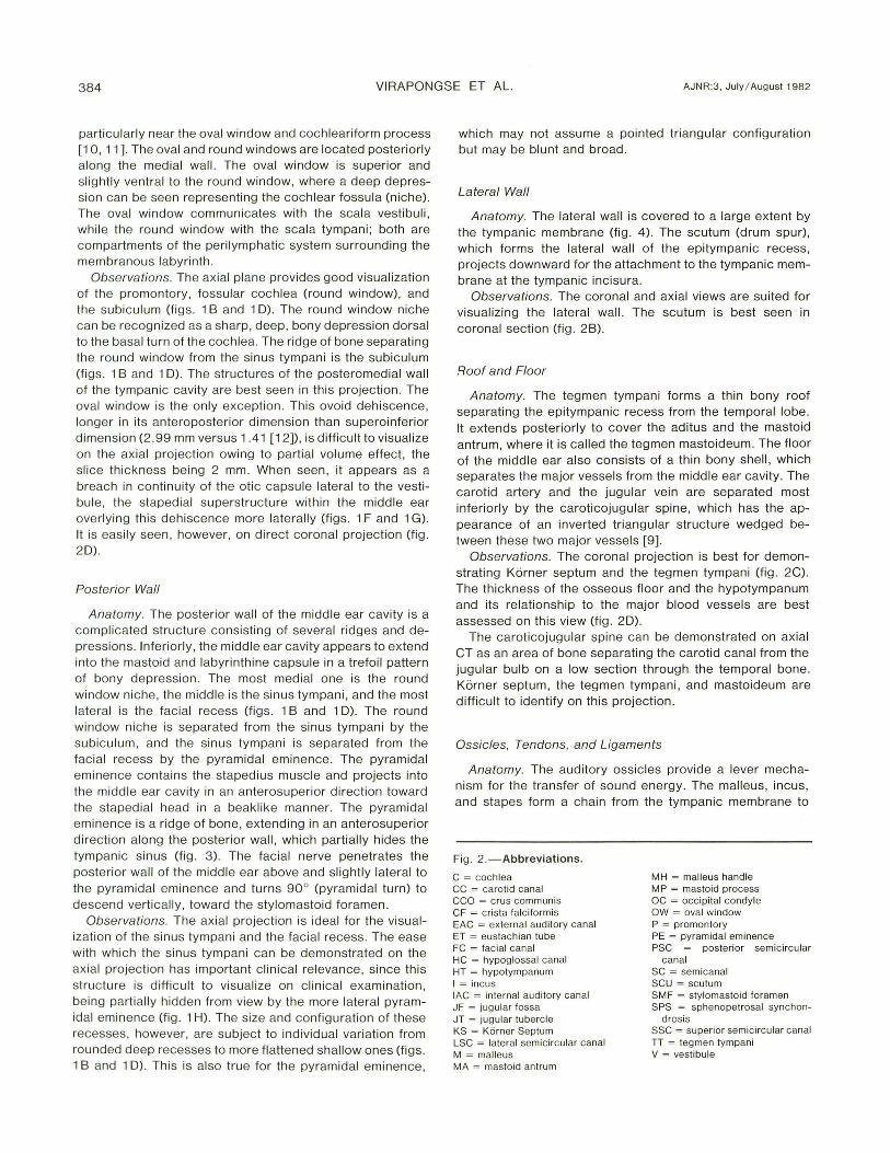
AJNR:3, July/ August 1982 CT OF TEMPORAL BONE 385
A
c
E
Fig. 2.-Coronal CT sections of dry skull, rig ht temporal bone. Successive slices 2 mm apart from anterior to posterior. A is most anterior . A , Through carotid canal and eustachian tube. B, Through cochlea and malleus. C,
B
D
F
Through basal run of cochlea of intern al auditory canal. D, Through internal audi tory canal and vestibule. E, Through vest ibule and jugular fossa. F, Through jugular fossa and vertica l part o f facial canal.

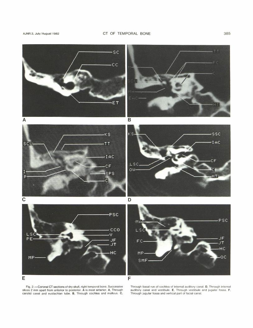
386 VIRAPONGSE ET AL. AJNR:3, July/ August 1982
Faciat cona l
Fig. 3. -Posteromedial aspect of left middle ear viewed from ex ternal ear. Promontory ex tends into two ridges, ponti culus superiorl y and subiculum inferiorly , forming ventral aspect of sinus tympani. Pyramidal eminence contains stapedius musc le, partiall y obscuring sinus tympani. (Reprin ted from [ 12].)
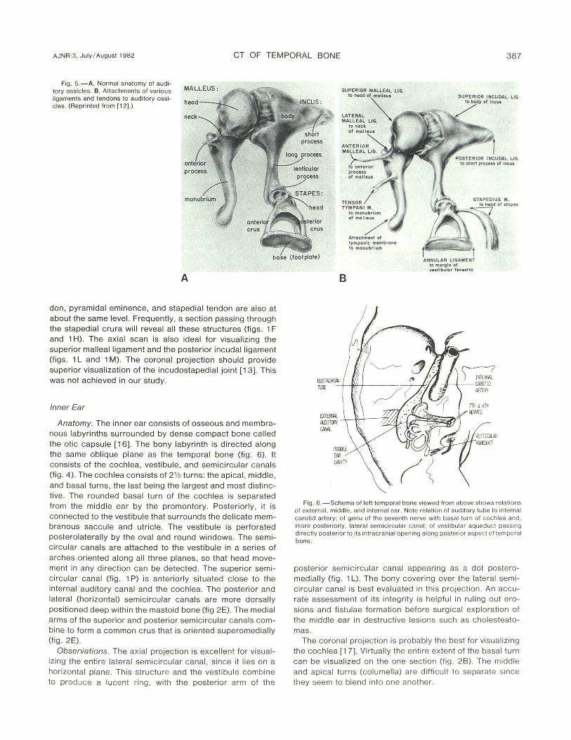
the bony labyrinth (fi g. 4) . The malleus, lying most ventrall y, consists of a head , a manubri um (handle), and an anterior process (fig . 5A) . The head arti culates wi th the body of the incus, while the manubrium and the lateral process are attached to the tympan ic membrane more laterall y . The head is round with a diameter of about 2- 3 mm. The anteri or process provides an attachment for the ante rior malleal ligament.
The incus, the largest of the three ossic les, has a body and a short and long process . The long process extends downward into the mesotympanum parallel and posteromedial to the malleal handle. Its most inferi or extension (the lenticu lar process) arti culates with the head of the stapes (fig. 1 H) [3, 13]. The short process projects dorsa lly from the body , where it is attached to the posterior wall of the epitympanic recess by the posterior incudal ligament (f igs. 1 L and 1 M). The body of the incus, inc luding its short process, is about 4-5 mm along its ante roposterior d imension. The epitympanic recess, where the inc udal body and mallea l head are located , narrows posteriorly and may be separated from the short process by 1-2 mm . This part of the epitympanic recess is called the fossa incudis (fi g. 1 L). The stapes consists of a head, which articulates with the incus, anterior and posterior cru ra, forming a crural arch (superstructure), and the stapedial foot plate . The foot plate configuration is complementary to the oval window.
The oss ic les are held suspended in the midd le ear by a seri es of struts consisti ng of ligaments and tendons (f ig. 58) . Some of these ligaments are merely folds of the mucous membrane that cover the entire middle ear cavity and the oss icul ar chain . These mucosal fo lds are considered ligaments, because they playa supporti ve role in maintain ing the integrity of the ossicu lar chain.
Latera ll y, the malleal handle is attached to the tympan ic
Fig . 4 .- Coronal view of right ear shows relati on between structu res comprising inner, middle, and ex tern al ear. Ossicular chain can be seen from its attachment to tympanic membrane, extending across middle ear to labyrinthine capsule. Eustachian tube occupy ing anterior wall of tympanic cavity passes anteromedially toward pharynx.
membrane. The anterior malleal ligament passes from the petrotympanic fi ssure (g laseri an fissure) to insert into the anterior malleal process. Mediall y, the tensor tympani tendon attaches itse lf to the neck of the malleus. It function s primarily to dampen the malleus when the malleus is subjected to vigorous sound vibrations (figs. 1 H and 11). Superiorly , the head of the malleus is attached to the roof of the epitympanic recess by the superi or mallealligament (fig. 1 N). The incus is supported by the posterior incudal ligament (fi g . 1 L) . The tendon of the stapedius musc le, whi ch inserts into the head of the stapes, serves a functi on similar to that of the tensor tympani tendon . The stapedial footplate is fastened to the rim of the oval window by the annular ligament.
From the foregoing description, it is quite apparent that the incus has the least support of all three ossic les, thus explaining its increased suscepti bility to traumatic dislocation.
Observations. The molar tooth conf igurat ion formed by the malleus and incus is a familiar lateral tomographic [9, 14 , 15] projection of the audi tory ossic les. On axial CT, secti ons are obtai ned perpend icular to the superorinferior orientati on of the ossic les . Essentiall y, sections pass through either head-body or the long processes of the ossic les. Higher cuts corresponding to the level of the internal auditory canal will usuall y also pass through the epitympanic recess and the incudomalleal articulati on (fi g. 1 L), whil e lower cuts corresponding to the external canal, drum, and mesotympanum will pass through the handle of the malleus and long process of the incus, both appearin g as two small densit ies (fig . 1 J) . The stapedial superstruc ture , formin g an arch over the oval window, lies on an ax ial plane , and, therefore, can be vi sualized in its entirety using thi s projection. The cochleari form process, tensor tympani ten-
AJNR:3, July I August 1982 CT OF TEMPORAL BONE 387
Fig. 5.-A, Normal anatomy of auditory ossic les. B, Attachments of various ligaments and tendons to audi tory ossicles . (Reprinted from [1 2].)
MALLEUS:
head
neck
SUPERIOR MALLEAL L1G. to head of molieul
LATERAL '" MALLEAL LIG. ~
to manubrium of mOI/ Attachment of tympanic membrane to manubrium
SUPERIOR INCUDAL LIG. to body of Incul
base (foot plate) t ANNULAR LIGAMENT
to moroln of vestibular fenestra
A
don , pyramidal eminence, and staped ial tendon are also at about the same level. Frequently , a section passing through the stapedial crura will reveal all these structures (figs. 1 F and 1 H). The ax ial scan is also ideal for visualizing the superior malleal ligament and the posterior incudal ligament (figs . 1 Land 1 M). The coronal projection should provide superior visualization of the incudostapedial joint [13] . This was not achieved in our study.
Inner Ear
Anatomy. The inner ear consists of osseous and membranous labyrinths surrounded by dense compact bone called the otic capsu le [16]. The bony labyrinth is directed along the same oblique plane as the temporal bone (fig. 6). It consists of the cochlea, vestibu le, and semicircu lar canals (fig. 4). The cochlea consists of 2'12 turns: the apical, middle , and basal turns, the last bei ng the largest and most distinctive . The rounded basal turn of the cochlea is separated from the middle ear by the promontory. Posteriorl y, it is con nected to the vestibule that su rrounds the delicate membranous saccule and utricle. The vestibule is perforated posterolaterally by the oval and round windows. The semicircu lar canals are attached to the vestibule in a series of arches oriented along all three planes, so that head movement in any direction can be detected. The superior semi circular canal (fig. 1 P) is anteriorly situated c lose to the internal auditory canal and the coch lea. The posterior and lateral (horizontal) semic ircular canals are more dorsally positioned deep within the mastoid bone (fig 2E). The medial arms of the superior and posterior sem icircu lar canals combine to form a common crus that is oriented superomedially (fig. 2E).
Observations. The axial projection is excellent for visualizing the entire lateral semicircular canal, since it lies on a horizontal plane. This structure and the vestibule combine to produce a lucent ring, with the posterior arm of the
B
Fig . 6.-Schema of left temporal bone viewed from above shows relations of ex ternal , middle, and internal ear. Note rel ati on of auditory tube to internal carotid artery; of genu of the seventh nerve with basal turn of coch lea and, more posteriorl y, lateral semic ircular canal; of vestibular aqueduc t passing directly posterior to its intracranial opening along posterior aspect of temporal bone.
posterior semicircular canal appearing as a dot posteromedially (fig. 1 L). The bony covering over the lateral sem icircu lar canal is best evaluated in this projection . An accurate assessment of its integrity is helpful in ruling out erosions and fistulae formation before surgical exploration of the middle ear in destructive lesions such as cholesteatomas.
The coronal projection is probably the best for vi sualizing the cochlea [1 7]. Virtually the entire extent of the basal turn can be visualized on the one section (fig. 2B). The midd le and apical turns (columella) are difficult to separate since they seem to blend into one another.
388 VIRAPONGSE ET AL. AJNR:3, July / August 1982
Internal Auditory Canal
Anatomy. The course of the internal auditory canal is directed along the coronal plane similar to, but slightly more cephalad than, the external auditory canal [18). The falc iform crest (crista falciformis), which consists of a thin piece of horizontal bone, is thickest at the fundus of the internal auditory canal. It divides the internal auditory canal into a superi or and inferior compartment [19-21] (fig. 2C). The facial nerve and the superior division of the vest ibular nerve lie in the superior compartment, wh ile the cochlear and the inferior division of the vestibular nerve lie in the inferior compartment. At the fundus of the canal, each nerve exits through its own foramen.
Observations. The ax ial projection is best suited for visuali zing the ex it foramina at the fundu s. At this point, the internal auditory canal forks in a Y configuration. The ventral arms represent the canals for the cochlear and faci al nerves; the dorsal for the vestibular nerves (fig. 1 F). The facial canal lies directly above the cochlear canal (figs. 1 L and 1 N). The coronal projection is ideal for visualizing the integrity of the falciform crest, which can be seen as a linear density medially dividing the intern al auditory canal into two compartments (fig. 20).
Aqueducts
Anatomy. The vestibu lar and cochlear aqueducts drain the endolymph and the perilymph, respective ly. The vestibular aqued uct consists of ventral and dorsal arms, which are directed posteriorly in a widened inverted V configuration [22-24). The termination of the aqueduct widens to accommodate the endolymphatic sac [25). This widening along the posterior aspect of the petrous bone forms a small plateau ca lled the foveate impression .
The cochlear aqueduct provides a potential communication with the subarachnoid space. It arises from the scala tympani near the round window and extends medially to open along the med ial aspect of the petrous bone be low the internal aud itory canal and is separated from the jugular fossa by a th in ridge of bone. Whil e the cochlear aq ueduct often assumes a funnel shape at its intracranial opening, the size and meatal configuration of both aqueducts are subject to considerable vari ation.
Observations. The ax ial projection is ideally su ited for demonstrating the coch lear aq ued uct. Thi s structure is usually seen at the level of the carotid canal and eustachian tube (fig. 10) and may appear as a th in, slitl ike structure much like the vestibular aqueduct or as a widened canal. It should not be mistaken for the intern al auditory canal, which lies just above it and is considerably larger. These two structures are separated by about 3 -4 mm of bone on the medial aspect of the petrous pyramid; seq uenti al scans shou ld be carefull y scrutinized in order to differentiate these structures. The vestibular aqueduct can also be visualized in this projection (fig. 1 L) lying medial to the posterior semicircular canal.
In our study, only the dorsal arm of the vestibular aqued uct can be visualized, probably owing to its larger size com-
pared with the ventral arm . On ax ial CT, th is canal widens posteriorly and merges with the foveate impression along the posterior aspect of the petrous pyramid.
Facial Canal
Anatomy. The fac ial canal can be d ivided into three sections: the first two parts are called the horizontal segments; the last the vertical segment [26 - 28).
The fac ial canal begins at the fundus of the internal auditory canal. It courses anteriorly ending at the geniculate gangl ion . At this point , the canal makes a hairpin turn and extends posteriorly along the medial wall of the tympanic cavity to the pyramidal eminence. This part of the canal lies superior to the semicanal for the tensor tympani, cochleariform process, oval window, lateral sem ic ircular canal, sinus tympani, and pyramidal eminence.
Behind the pyram idal eminence, the canal turns sharp ly downward toward the stylomastoid foramen and is related anteriorly to the external auditory canal and middle ear and posteriorly to the mastoid air cells [29 , 3D).
Observations. The axial projection usuall y provides excellent visualization of the horizontal parts of the fac ial canal. It is particularly good for demonstrating the first segment of the facial nerve as it leaves the internal auditory canal (figs . 1 L and 1 N).
The second part of the facia l canal traversing the middle ear is difficult to visualize, owing to its thin bony covering, which is microscopically perforated by blood vessels [10, 11). Occasionall y, when this bony covering is th ick, the entire horizontal course of the facial nerve can be demonstrated on one section .
In the normal adu lt, the canal of the descending segment of the fac ial nerve is difficu lt to identify in the axial plane due to surrounding mastoid air cells . It can be readily identified in young children and in patients with mastoid disease who have obliterated masto id air cells. The coronal projec tion is helpful for visuali zing the genu of the facial nerve. It is also useful in assess ing the vertical part of the facial nerve (fig . 2F).
Reconstruction
In a cooperative patient , it is possible to obtain a series of ax ial scans and reform at them in any number of planes. This technique has the advantage of being able to display the complex anatomy in all of the conventional projections, although only exposing the patient to radiation one time.
There are two technical drawbacks to this technique. The resolution of reformatted images along the z ax is is limited to 1.5-2.0 mm. As a result , some slight degradation of the image is expected when compared with direct coronal or sagittal scans. Patient motion is also very critical when evaluat ing small bony structures. The minute prox imity of the many important intratemporal structures make even a small amount of patient motion intolerable . Therefore , it is desirable to perform the scanni ng seq uence as quickly as possible to limit patient motion.
AJNR:3, July / August 1 982 CT OF TEMPORAL BONE 389
Comment
A large number of structures previously not vi sualized or poorly visualized by other means can now be seen by CT. These inc lude: the tympanic membrane, the ossic les and their assoc iated tendons and ligaments, the eustachian tube, and the semicanal for the tensor tympani , the cochleariform process. The round window niche, subiculum , sinus tympani , the first portion of the fac ial canal, the canals for the vestibular and cochlear nerves, and the cochlear aqueduct can also be seen.
For maximum resolution, scanning patients d irectly in the two projections is advantageous. When this is not possible, reformatted images can be obtained, although there is some loss in resolution .
There are many c linical implicati ons of thi s new methodology. CT provides a prec ise technique for the evaluation of soft-tissu e masses within the ai r-fill ed middle ear and mastoid . Defining the extent of erosion or destructi on of the walls of the middle ear, the capsule of the semic ircular canals, and the ossicular chain is crucial in the evaluation and treatment of cholesteatomas and other middle ear lesions. It is also very helpful in evaluating postoperative complications from a mastoidectomy. CT is espec ially useful in assessing the tympanic membrane and in visuali zing partl y hidden struc tures such as the sinus tympani. Detaj led anatomic knowledge is essential fo r the increasingly important role that high-resolution CT can be expected to have in the evaluation of the normal and abnormal temporal bone. This study offers some of that informati on.
REFERENCES
1. Hanafee WN , Mancuso AA , Winter J , Bergstrom L. Edge enhancement computed tomograph y scanning in inflammatory lesions of the midd le ear. Radiology 1980;136 : 77 1-775
2 . Shaffer KA, Bolz OJ , Haughton VM . Manipulation of CT data for temporal bone imaging . Radio logy 1980;137 : 825-829
3 . Lloyd GAS, Duboulay GH , Phelps PO, Pullc iino P. The demonstration of the auditory ossic les by high resolution CT. Neuraradiology 1979; 18: 243-248
4 . Bentson JR , Mancuso AA , Winter J , Hanafee WN . Combined gas c isternography and edge-enhanced computed tomography of the intern al auditory canal. Radiology 1980;136: 777 - 779
5. Shaffer KA , Haughton VM, Wilson CR. High reso lution computed tomography of th e temporal bone. Radiology 1980;134 : 409- 4 14
6. Shaffer KA , Haughton VM . Thin section computer tomography of th e temporal bone. Laryngoscope 1980;90: 1 099-11 05
7 . Hanafee WN, Gussen R. Correlation of basal projection tomography in c linica l problems. Radiol Clin North Am 1974;12 : 419-429
8 . Hounsfield GN. Picture quali ty of computed tomography. AJR 1976;127 :3-9
9 . Guinto TC, Himadi GM . Tomographic anatomy of the ear. Radiol Clin North Am 1974 ;3: 405-417
10. Wilbrand HF. Mul tidirectional tomography of the fac ial canal. Acta Radiol [Oiagn] (Stockh) 1975; 16 : 654-672
11 . Wil brand HF, Bergstron B. Mu ltidirectional tomography of defec ts of the fac ial canal. Acta Radiol [Oiagnj (Stockh) 1975; 16 : 223-240
12. Anson BJ, Donaldson JA . Surgi ca l anatomy of the temporal bone and ear, 2d ed. Phil adelphia: Saunders, 1973 : 239
13. Matsubara R, Konrad H, Hanafee WN . Incudostaped ial joint in health and disease. AJR 1978;13 1 :307-3 10
14. Schatz CJ, Vignaud J. The inclined latera l projection : a new view in temporal bone tomography. Radiology 1976 ;11 8: 335- 361
15. Potter GO. The lateral prOjec tion in tomography of the petrous pyramid . AJR 1968 ;104 :194-200
16. Donaldson JS. Normal anatomy of the inner ear . Otol Clin North Am 1975;2 :267 - 269
17. Vignaud J, Juster M, Lerich H, Lichtenberg R, Korach G. Radioanatomie de la cochlea. Acta Radio/ 1969 ;9: 11 7 -1 22
18. Valvassori GE, Pierce RH . The normal auditory canal. AJR 1964;92 : 1 232- 1 240
19 . Pait TG, Zeal A, Harri s FS, Paullus WS, Rh oton A. Microsurg ical anatomy and dissection of the temporal bone. Surg Neural 1977;8: 363 - 392
20. Rhoton AL. M ic rosurgery of the in ternal acoustic meatus. Surg Neural 1974;2: 311-3 18
2 1. Vignaud J, Grall Y, Elbaz P, Paleirac R. Rad iologica l anatomy of th e c istern of th e auditory canal. Adv Otorhinolaryngol 1974 ;21 : 61 - 75
22 . Ru mbaugh CL, Bergeron T, Scanlan RL. Vesti bu lar aqueduc t in Menier's d isease. Radiol Clin North Am 1974;12: 517-525
23. Stahle J , Wilbrand H. The vestibular aqueduct in patients wi th Meniere 's disease . Acta Otolaryngol (Stockh) 1974;78: 36-48
24. Ogura Y, Clem is JD. A study of the gross anatomy of the human vestibu lar aqueduct. Ann Otol Rhinol Laryngol 1971 ;80 : 81 3 - 825
25 . Wilbrand HF, Rask-Andersen H, Gilstring D. The vestibular aqueduct and the paravestibular canal. Acta Radiol [Oiagn] (Stockh) 1974; 15: 337 -355
26. Vignaud J, Burl amaqui BJ , Aubin ML. Etude tomog raphique de L 'aqueduc de fallope. J Radio/ 1970;5 1 : 1 27 - 132
27 . Kudo H, Nori S. Tomography of the facial nerve in the temporal bone. Acta Anat (Basel) 1974;90 : 467 -480
28. Don aldson JA, Anson BJ . Surgical anatomy of the facial nerve. Otolaryngol Head Neck Surg 1974;7 : 280-308
29. Ericson S, Liliequist D. Tomographic examination of the verti ca l segment of the fac ial canal. Acta Radiol [Oiagn] (Stockh) 1973;14 : 673 - 681
30 . Ekstrand T , Eri cson S, Liliequist 0 , Wiberg A. Tomographic examinat ion of th e vert ica l part of the fac ial canal in cases of Bell' s Palsy. Acta Otolaryngol (Stockh) 1974 ;88 : 423-43 1