range construction and maintenance
TRANSCRIPT

OPERATIONAL TRAINING
RANGE CONSTRUCTION AND MAINTENANCE
(ENGLISH)
(This publication supersedes B-GL-381-002/TS-000 dated 2005–05–01)
Issued on the Authority of the Chief of the Land Staff
B-GL-381-002/TS-001
WARNING
ALTHOUGH NOT CLASSIFIED, THIS PUBLICATION, OR ANY PART OF IT, MAY BE EXEMPT FROM DISCLOSURE TO THE PUBLIC UNDER THE ACCESS TO INFORMATION ACT. ALL ELEMENTS OF INFORMATION CONTAINED HEREIN MUST BE CLOSELY SCRUTINIZED TO ASCERTAIN WHETHER OR NOT THE PUBLICATION OR ANY PART OF IT MAY BE RELEASED.
OPERATIONAL TRAINING
RANGE CONSTRUCTION AND MAINTENANCE
(ENGLISH)
(This publication supersedes B-GL-381-002/TS-000 dated 2005–05–01)
Issued on the Authority of the Chief of the Land Staff OPI: DAT RTAM 2010–12–01
B-GL-381-002/TS-001
WARNING
ALTHOUGH NOT CLASSIFIED, THIS PUBLICATION, OR ANY PART OF IT, MAY BE EXEMPT FROM DISCLOSURE TO THE PUBLIC UNDER THE ACCESS TO INFORMATION ACT. ALL ELEMENTS OF INFORMATION CONTAINED HEREIN MUST BE CLOSELY SCRUTINIZED TO ASCERTAIN WHETHER OR NOT THE PUBLICATION OR ANY PART OF IT MAY BE RELEASED.

Range Construction and Maintenance
FOREWORD1. In accordance with the transfer of responsibilities announced by NDHQ under 7795–0 (DCDS) dated 27 January 1995, B-GL-381-002/TS-001 Operational Training, Part 2, Range Construction and Maintenance, is issued on authority of the Chief of the Land Staff.
2. This publication is effective upon receipt and supersedes B-GL-381-002/TS-001 Operational Training, Volume 3, Part 2, Range Construction and Maintenance (2005–05–01).
3. Suggestions for changes shall be forwarded through normal channels to Land Force Doctrine and Training System Headquarters, Directorate Army Training, attention Ranges and Training Area Management.
i

Range Construction and Maintenance
TABLE OF CONTENTS FOREWORD .......................................................................................................................... i CHAPTER 1 GENERAL
SECTION 1 INTRODUCTION ..........................................................................................1-1 101. Policy ......................................................................................................................1-1 102. Applicability ..............................................................................................................1-1 103. Authority ...................................................................................................................1-1 104. Amendment ..............................................................................................................1-1 105. Aim ......................................................................................................................1-1
SECTION 2 GOVERNANCE ............................................................................................1-2 106. Responsibilities ........................................................................................................1-2 107. Range Management Plans.......................................................................................1-3
SECTION 3 INSPECTION AND AUTHORIZATION OF LAND RANGES AND TRAINING AREAS...............................................................................1-5
108. General.....................................................................................................................1-5 109. Responsibilities ........................................................................................................1-5 110. Authorization of Land Ranges and Training Areas...................................................1-6 111. Designation of Land Ranges and Training Areas.....................................................1-6 112. Classification of Land Ranges and Training Areas...................................................1-7 113. Categories of UXO Contamination ...........................................................................1-7 114. Types of Dangerous Areas.......................................................................................1-8 115. Status of Land Ranges and Training Area Authorization .........................................1-8 116. Condition of Land Ranges and Training Areas.........................................................1-9 117. Inspection of Land Range and Training Areas .........................................................1-9 118. Inspection of Indoor Ranges ..................................................................................1-11
ANNEX A TO CHAPTER 1 RTA REFERENCES................................................................... 1A-1 CHAPTER 2 ESTABLISHMENT OF RANGES AND TRAINING AREAS
SECTION 1 PLANNING ...................................................................................................2-1 201. General.....................................................................................................................2-1 202. Range and Training Area Requirements..................................................................2-1 203. Establishing Ranges.................................................................................................2-2 204. Setting Up a Range ..................................................................................................2-2 205. Inspection and Maintenance Checklists ...................................................................2-3 SECTION 2 RANGE AND TRAINING AREA SIGNS...........................................................2-3 206. General.....................................................................................................................2-3 207. Location of Boundary Signs .....................................................................................2-3
SECTION 3 RANGE AND TRAINING AREA SECURITY ................................................2-4 208. Fences......................................................................................................................2-4 209. Gates and Barricades...............................................................................................2-4 210. Range Boundaries....................................................................................................2-4 211. Arc of Fire Markers...................................................................................................2-5 212. Range Flags .............................................................................................................2-5 213. Communications.......................................................................................................2-6
SECTION 4 TARGETS.....................................................................................................2-6 214. General.....................................................................................................................2-6 215. Types ......................................................................................................................2-7 216. Accessories for Conventional Ranges......................................................................2-8 217. Targets and Accessories for 25 Metre Ranges ........................................................2-9 218. Targets and Accessories for Individual and Fire-Team Combat Ranges .................2-9 219. Targets and Accessories for AFV and Anti-Tank Ranges ........................................2-9
iii

B-GL-381-002/TS-001
SECTION 5 DANGER AREAS.......................................................................................2-11 220. Danger area Templates .........................................................................................2-11
SECTION 6 RANGE FACILITIES ..................................................................................2-12 221. Target Stores and Workshop .................................................................................2-12 222. Troop Shelter .........................................................................................................2-12 223. Bunker ...................................................................................................................2-12 224. Latrine ...................................................................................................................2-13
SECTION 7 ENVIRONMENT.........................................................................................2-13 225. Sustainable Range and Training Areas .................................................................2-13 226. Environmental Officer Responsibilities...................................................................2-14 227. Precautions ............................................................................................................2-14 228. Control ...................................................................................................................2-14 229. Water Courses .......................................................................................................2-15 230. Roads ...................................................................................................................2-15 231. Tracks, Trails and Fording Sites ............................................................................2-15 232. Wildlife ...................................................................................................................2-15 233. Woodcutting ...........................................................................................................2-16 234. Trenches and Fortifications....................................................................................2-16 235. Human Waste ........................................................................................................2-16 236. Vehicles..................................................................................................................2-17 237. Engineering Work...................................................................................................2-17
SECTION 8 REPORTS AND ACCOUNTS ....................................................................2-18 ANNEX A TO CHAPTER 2 .....................................................................................................2A-1 ANNEX B TO CHAPTER 2 .....................................................................................................2B-1 ANNEX C TO CHAPTER 2 RANGE CONSTRUCTION CONSIDERATIONS ....................... 2C-1 ANNEX D TO CHAPTER 2 .................................................................................................... 2D-1 ANNEX E TO CHAPTER 2......................................................................................................2E-1 CHAPTER 3 DIRECT FIRE RANGES
SECTION 1 INTRODUCTION..........................................................................................3-1 SECTION 2 COMMON FEATURES OF DIRECT-FIRE RANGES...................................3-1 SECTION 3 15 METER CONVENTIONAL RANGE.........................................................3-2 SECTION 4 25 METER CONVENTIONAL RANGE WITH NO DANGER AREA .............3-2 SECTION 5 25 METER CONVENTIONAL RANGE WITH DANGER AREA ...................3-5 SECTION 6 CONVENTIONAL RANGES.........................................................................3-6 SECTION 7 AUSTERE RANGE.....................................................................................3-22 SECTION 8 BAFFLE RANGES......................................................................................3-24 SECTION 9 TANK AND ANTI-TANK RANGES .............................................................3-26 SECTION 10 TOW RANGE .............................................................................................3-29 SECTION 11 Armoured Fighting Vehicle BATTLE RUN..................................................3-30 SECTION 12 INDIVIDUAL/TEAM BATTLE SHOOTING RANGE....................................3-31 SECTION 13 25 M GALLERY RANGES (INDOOR) ........................................................3-33 SECTION 14 ARMOURED FIGHTING VEHICLE SIMULATION FACILITIES.................3-42 SECTION 15 LIVE-FIRE SHOOT-HOUSE.......................................................................3-44
ANNEX A TO CHAPTER 3 CONVENTIONAL RANGE INSPECTION CHECKLIST .............3A-1APPENDIX 1 TO ANNEX A TO CHAPTER 3 CONVENtIONAL RANGE MAINTENANCE
CHECKLIST .............................................................................................3A1-1 ANNEX B TO CHAPTER 3 GALLERY (INDOOR) RANGE MAINTENANCE CHECKLIST ..3B-1 ANNEX C TO CHAPTER 3 LIVE-FIRE SHOOT HOUSE INSPECTION CHECKLIST .......... 3C-1 CHAPTER 4 INDIRECT FIRE RANGES
SECTION 1 INTRODUCTION..........................................................................................4-1 SECTION 2 60 MM MORTAR..........................................................................................4-2
iv

Range Construction and Maintenance
SECTION 3 81 mm MORTAR ..........................................................................................4-3 SECTION 4 14.5 mm ARTILLERY AND 25 mm MORTAR TRAINER RANGES .............4-3 SECTION 5 105 mm AND 155 mm ARTILLERY RANGES .............................................4-4
CHAPTER 5 MISCELLANEOUS RANGES SECTION 1 DEMOLITION RANGE..................................................................................5-1 SECTION 2 FRAGMENTATION GRENADE RANGE......................................................5-3
504. General.....................................................................................................................5-3 505. Danger Area .............................................................................................................5-3 506. Fencing.....................................................................................................................5-3 507. Throwing Bay ...........................................................................................................5-3 508. Control Tower...........................................................................................................5-3 509. Assembly Shelter .....................................................................................................5-3 510. View Ports ................................................................................................................5-4 511. Maintenance.............................................................................................................5-4 512. Communications.......................................................................................................5-5 513. Targets .....................................................................................................................5-5 514. Posting Bunker .........................................................................................................5-5
SECTION 3 M 203 GRENADE LAUNCHER RANGE ......................................................5-5 515. General.....................................................................................................................5-5 516. Site ......................................................................................................................5-5 517. Range Layout ...........................................................................................................5-6
SECTION 4 MARCOM WEAPON RANGES ....................................................................5-6 518. Authority ...................................................................................................................5-6 519. Reference Book........................................................................................................5-6
SECTION 5 AIR WEAPON RANGES...............................................................................5-7 520. Authority ...................................................................................................................5-7 521. Reference Book........................................................................................................5-7
SECTION 6 ADATS AND GDF 005 35 mm ANTI-AIRCRAFT GUN ................................5-7 522. Site ......................................................................................................................5-7 523. Range Layout ...........................................................................................................5-7 524. Arcs of Fire and Flags ..............................................................................................5-7
SECTION 7 SKEET/TRAP RANGE..................................................................................5-8 525. General.....................................................................................................................5-8 526. Site ......................................................................................................................5-8 527. Safety Measures ......................................................................................................5-8 528. Ammunition ..............................................................................................................5-8 529. Target Throwers .......................................................................................................5-8 530. Targets .....................................................................................................................5-9 531. Maintenance.............................................................................................................5-9 532. Range Layout ...........................................................................................................5-9 533. Skeet or Trap Houses ..............................................................................................5-9
SECTION 8 SKEET RANGE ..........................................................................................5-10 534. Range Configuration ..............................................................................................5-10 535. Firing Points ...........................................................................................................5-10 536. Barrier Fence for Adjacent Skeet Ranges..............................................................5-10 537. Field Firing Skeet Range Layout ............................................................................5-10 538. Firing Points ...........................................................................................................5-11
SECTION 9 TRAP RANGES..........................................................................................5-11 539. Trench 5-11 540. Firing Points ...........................................................................................................5-11
ANNEX A TO CHAPTER 5..................................................................................................... 5A-1
v
B-GL-381-002/TS-001
APPENDIX 1 TO ANNEX A TO CHAPTER 5 PERMANENT DEMOLITION RANGE MAINTENANCE CHECKLIST .................................................................5A1-1
ANNEX B TO CHAPTER 5 Gallery (INDOOR) RANGE MAINTENANCE CHECKLIST .......5B-1 ANNEX C TO CHAPTER 5 LIVE-FIRE SHOOT HOUSE INSPECTION CHECKLIST .......... 5C-1 CHAPTER 6 TRAINING FACILITIES
601. General ....................................................................................................................6-1 SECTION 1 OBSTACLE COURSE..................................................................................6-1
602. Characteristics .........................................................................................................6-1 603. Types of Obstacles ..................................................................................................6-1
SECTION 2 URBAN OPERATIONS SITES.....................................................................6-2 604. General ....................................................................................................................6-2 605. Characteristics .........................................................................................................6-2 606. Design Considerations .............................................................................................6-4 607. Three-Dimensional Battlespace ...............................................................................6-6 608. Site .....................................................................................................................6-7 609. Construction .............................................................................................................6-8
SECTION 3 SMALL ARMS TRAINER............................................................................6-10 610. General ..................................................................................................................6-10 611. Safety Precautions .................................................................................................6-10 612. Maintenance...........................................................................................................6-10
SECTION 4 RAPPEL TOWER.......................................................................................6-11 613. General ..................................................................................................................6-11 614. Tower Dimensions .................................................................................................6-11 615. Design ...................................................................................................................6-11 616. Maintenance...........................................................................................................6-11
SECTION 5 GAS HUT ...................................................................................................6-12 617. General ..................................................................................................................6-12 618. Safety Precautions .................................................................................................6-13 619. Equipment Required ..............................................................................................6-13 620. Field Expedient Gas Hut ........................................................................................6-13
SECTION 6 CLOSE ENGAGEMENT AMMUNITION SIMULATION SYSTEMS ...........6-17 621. General ..................................................................................................................6-17 622. Ceass Facility Requirements .................................................................................6-17 623. Use Of Ceass Within Dnd And Non-Dnd Properties ..............................................6-18
SECTION 7 CONVOY IMPROVISED EXPLOSIVE DEVICE RANGE...........................6-19 624. General ..................................................................................................................6-19 625. Range Layout.........................................................................................................6-19 626. Site ...................................................................................................................6-20
SECTION 8 BATTLE INOCULATION RANGES ...........................................................6-20 627. General ..................................................................................................................6-20 628. Range Layout.........................................................................................................6-20 629. Site ...................................................................................................................6-21
SECTION 9 FORWARD OPERATING BASES..............................................................6-22 630. General ..................................................................................................................6-22 631. Layout ...................................................................................................................6-22 632. Site ...................................................................................................................6-23
ANNEX A TO CHAPTER 6 CONVENTIONAL SMALL ARMS RANGE INSPECTION CHECKLIST ...............................................................................................6A-1
ANNEX B TO CHAPTER 6 DEMOLITION RANGE CHECKLIST ..........................................6B-1 ANNEX C TO CHAPTER 6 GALLERY (INDOOR) SMALL ARMS RANGE INSPECTION
CHECKLIST .............................................................................................. 6C-1
vi

Range Construction and Maintenance
ANNEX D TO CHAPTER 6 GAS HUT INSPECTION CHECKLIST ....................................... 6D-1 ANNEX E TO CHAPTER 6 LIVE-FIRE SHOOT HOUSE INSPECTION CHECKLIST .......... 6E-1 ANNEX F TO CHAPTER 6 SKEET & TRAP INSPECTION CHECKLIST ............................. 6F-1 ANNEX G TO CHAPTER 6 TRAINING AREA INSPECTION CHECKLIST ..........................6G-1 ANNEX H TO CHAPTER 6 CEASS INSPECTION CHECKLIST........................................... 6H-1 ANNEX I TO CHAPTER 6 OBSTACLE COURSE INSPECTION CHECKLIST ......................6I-1 ANNEX J TO CHAPTER 6 RAPPEL TOWER INSPECTION CHECKLIST............................6J-1 ANNEX K TO CHAPTER 6 SMALL ARMS TRAINERS INSPECTION CHECKLIST............ 6K-1 ANNEX L TO CHAPTER 6 URBAN OPERATIONS TRAINING SYSTEM INSPECTION
CHECKLIST ...............................................................................................6L-1 ANNEX M TO CHAPTER 6 REDUCED TEMPLATE BAFFLE RANGE CHECK LIST .........6M-1 ANNEX N TO CHAPTER 6 RANGE CONTROL AGENCY CHECKLIST .............................. 6N-1 ANNEX O TO CHAPTER 6 GRENADE RANGE INSPECTION CHECKLIST .......................6O-1 CHAPTER 7 GLOSSARY AND DEFINITIONS
vii


Range Construction and Maintenance
TABLE OF FIGURES Figure 2A–1: Arc of fire markers ............................................................................................. 2A-1 Figure 2A–2: Range gate support showing barrier pivot......................................................... 2A-1 Figure 2A–3: Range gate support frame showing lock cover ................................................. 2A-2 Figure 2A–4: Range gate supports with concrete base .......................................................... 2A-3 Figure 2A–5: Range gate supports and barrier....................................................................... 2A-4 Figure 2B–1: 1.2 m and 1.8 m Targets used for Rapid Fire and Application Practice. These
targets are constructed locally by base workshop ..................................... 2B-1 Figure 2B–2: Falling steel plate target .................................................................................... 2B-1 Figure 2B–3: 12/59 Target for snap-shooting ......................................................................... 2B-2 Figure 2B–4: Figure targets .................................................................................................... 2B-3 Figure 2B–5: Screen for GPMG.............................................................................................. 2B-4 Figure 2B–6: Conventional range target marking devices ...................................................... 2B-4 Figure 2B–7: 25 m Range Target Frame ................................................................................ 2B-5 Figure 2B–8: 25 m Targets for application and grouping practices......................................... 2B-5 Figure 2B–9: 25 m targets for fire and movement practice ..................................................... 2B-6 Figure 2B–10: Tank turret target ............................................................................................. 2B-6 Figure 2B–11: Head-on tank target......................................................................................... 2B-7 Figure 2B–12: Broadside tank target ...................................................................................... 2B-7 Figure 2B–13: Soft-skinned troop carrier ................................................................................ 2B-8 Figure 2B–14: Anti-tank gun target ......................................................................................... 2B-8 Figure 2B–15: Machine-gun post ............................................................................................ 2B-9 Figure 2B–16: Tank pop-up and moving target..................................................................... 2B-10 Figure 2B–17: AFV target sections ....................................................................................... 2B-11 Figure 2B–18: AFV target end view ...................................................................................... 2B-11 Figure 2B–19: AFV target side view...................................................................................... 2B-12 Figure 2B–20: AFV target sectional view .............................................................................. 2B-12 Figure 2D–1: Range boundary................................................................................................ 2D-1 Figure 2D–2: Keep out sign .................................................................................................... 2D-2 Figure 2D–3: Défense de passer ............................................................................................ 2D-2 Figure 2D–4: Barrier sign ........................................................................................................ 2D-3 Figure 2D–5: No live ammunition or explosives are permitted in this room............................ 2D-3 Figure 3–1: 25 metre range with no danger area template ........................................................3-3 Figure 3–2: Example photo showing a 25 yard range with no danger area...............................3-4 Figure 3–3: Conventional range template, 5.56 mm ..................................................................3-8 Figure 3–4: Conventional range template 7.62 mm ...................................................................3-9 Figure 3–5: Dimensions of danger area for a 5.56 mm conventional range ............................3-10 Figure 3–6: Danger areas for adjoining ranges........................................................................3-11 Figure 3–7: Interim conventional range layout .........................................................................3-13 Figure 3–8: Stop Butt ...............................................................................................................3-13 Figure 3–9: Bullet catcher ........................................................................................................3-14 Figure 3–10: Marker’s gallery (Concrete)................................................................................3-17 Figure 3–11: Formation of scoops on mantlet.........................................................................3-18 Figure 3–12: Hythe pattern target frame ..................................................................................3-20 Figure 3–13: Hythe pattern target frame ..................................................................................3-21 Figure 3–14: Remote control target range ...............................................................................3-21 Figure 3–15: Typical stop butt of an austere range..................................................................3-23 Figure 3–16: Natural stop butt of an austere range .................................................................3-23 Figure 3–17: 300 m baffle range with deflectors ......................................................................3-25 Figure 3–18: Anti-tank firing bay (TPT) ....................................................................................3-27
ix

B-GL-381-002/TS-001
Figure 3–19: Anti-tank firing bay (HEAT) .................................................................................3-28 Figure 3–20: Range with fixed firing positions .........................................................................3-30 Figure 3–21: Team battle shooting range................................................................................3-32 Figure 3–22: Linatex curtain with the target boards in front.....................................................3-35 Figure 3–23: Figure 11 targets in front of the stop butt............................................................3-35 Figure 3–24: Bullet catcher: tilted steel plate ...........................................................................3-37 Figure 3–25: Double curtain: inclined metal plate Figure 3–26: Curved metal plate ..............3-38 Figure 3–27: Example of an indoor range................................................................................3-42 Figure 3–28: LAV crew gunnery trainer ...................................................................................3-43 Figure 3–29: Example of LAV simulation facility......................................................................3-44 Figure 3–30: Ballistic panel corner construction. .....................................................................3-52 Figure 3–31: Shock absorbing concrete corner intersection....................................................3-52 Figure 3–32: Shock absorbing concrete wall intersection........................................................3-53 Figure 3–33: Preliminary elevation plan steel panel shoot-house ...........................................3-54 Figure 3–34: Preliminary floor plan steel panel shoot-house...................................................3-55 Figure 3–35: Ballistic roof design (concept).............................................................................3-56 Figure 3–36: Preliminary floor plan shock absorbing concrete shoot-house ...........................3-57 Figure 3–37: Steel panel wall configuration .............................................................................3-58 Figure 3–38: Sample environmental cover exterior .................................................................3-59 Figure 3–39: Sample environmental cover interior ..................................................................3-60 Figure 3–40: Shock absorbing concrete ..................................................................................3-61 Figure 5–1: Demolition range...................................................................................................5A-1 Figure 5–2: Destruction area layout.........................................................................................5A-2 Figure 5–3: Grenade throwing bay ..........................................................................................5A-3 Figure 5–4: Viewports ..............................................................................................................5A-4 Figure 5–5: Tactical Grenade Posting Type “A” Target Trench ...............................................5A-5 Figure 5–6: Tactical Grenade Posting Type “A” Target Trench Alternative Materials .............5A-6 Figure 5–7: Tactical Grenade Posting Type “B” Target Bunker...............................................5A-7 Figure 5–8: Tactical Grenade Posting Type “C” Target Window .............................................5A-8 Figure 5–9: Grenade launcher range firing point .....................................................................5A-9 Figure 5–10: M 203 grenade launcher range layout ..............................................................5A-10 Figure 5–11: Sample trap house below ground and surface built..........................................5A-11 Figure 5–12: Typical layout of a skeet range.........................................................................5A-12 Figure 5–13: Typical trap field layout .....................................................................................5A-12 Figure 5–14: Skeet range barrier fence .................................................................................5A-13 Figure 6–1: Typical urban area.................................................................................................6-3 Figure 6–2: City core mixed building types ................................................................................6-4 Figure 6–3: Commercial ribbon..................................................................................................6-5 Figure 6–4: Residential sprawl...................................................................................................6-5 Figure 6–5: Outlying industrial areas .........................................................................................6-6 Figure 6–6: The urban environment...........................................................................................6-7 Figure 6–7: UO site layout .........................................................................................................6-8 Figure 6–8: Building types .........................................................................................................6-9 Figure 6–9: Structural steel and concrete construction..............................................................6-9 Figure 6–10: Sea-can construction..........................................................................................6-10 Figure 6–11: Rappel tower elevations .....................................................................................6-12 Figure 6–12: Tower bracing members .....................................................................................6-12 Figure 6–13: Gas hut floor plan ...............................................................................................6-14 Figure 6–14: Gas hut electrical plan ........................................................................................6-15 Figure 6–15: Gas hut ventilation plan ......................................................................................6-16 Figure 6–16: Gas hut elevation and cross section...................................................................6-17
x

Range Construction and Maintenance
Figure 6–17: CEASS facility.....................................................................................................6-19 Figure 6–18: Convoy IED range layout ....................................................................................6-20 Figure 6–19: Battle inoculation range ......................................................................................6-22 Figure 6–20: Forward operating base layout ...........................................................................6-23 Figure 6–21: Elevated Observation Post (OP).........................................................................6-24 Figure 6–22: Elevated OP base platform.................................................................................6-24 Figure 6–23: Elevated OP cross section..................................................................................6-25 Figure 6–24: Elevated OP column placement..........................................................................6-25 Figure 6–25: Elevated OP floor plan ........................................................................................6-26 Figure 6–26: Elevated OP elevations.......................................................................................6-26 Figure 6–27: Elevated OP outer lintel details...........................................................................6-27 Figure 6–28: Elevated OP column assembly ...........................................................................6-27 Figure 6–29: Elevated OP base plate ......................................................................................6-28
xi


Range Construction and Maintenance
CHAPTER 1 GENERAL
SECTION 1 INTRODUCTION
101. POLICY
1. Chapter 1 establishes Canadian Forces (CF) policy governing the administration and control of ranges and training areas (RTA).
2. B-GW-100-D56/AA-001 CF Policy for Controlling Civil Access to Dangerous DND Lands, Ranges and Training Areas (DNDP 56) contains broad policy guidance and direction pertaining to the control of civil access and protection of the public from injury or death.
3. Detailed policy and procedures governing the day-to-day operation of RTA, range and training area safety, environmental and resource management are contained in applicable references.
102. APPLICABILITY
1. This publication applies to all land based ranges, training areas, training facilities and land (DND and non-DND) used by all elements of the CF for training and testing purposes.
103. AUTHORITY
1. In accordance with the transfer of responsibilities announced by NDHQ under 7795–0 (DCDS) 27 January 1995, the Range Construction and Maintenance manual is issued on the authority of the Chief of the Land Staff (CLS). This publication is the Canadian Forces policy for land based RTA construction and maintenance. In the event of a conflict between this and other publications or instructions, the matter shall be referred to Land Force Doctrine and Training System Headquarters (LFDTS HQ), attention Directorate Army Training (DAT) Ranges and Training Area Management (RTAM).
2. The construction and maintenance standards presented in this volume correspond to minimum requirements. In most cases, additional design specifications and project approvals will be required to enable construction and/or major maintenance projects to proceed. On-site authorities may improve or modify facilities to meet their specific environmental training needs.
104. AMENDMENT
1. Requests to amend this publication may be staffed through the chain of command to LFDTS HQ Kingston, attention DAT RTA. This publication will be available in electronic format at the Army Electronic Library along with a list of amendments.
105. AIM
1. The aim of B-GL-381-002/TS-001 is to establish the basic requirements for design, functionality and maintenance in support of operational training.
2. These basic standards shall be used by facility managers and Engineer Officers when developing plans for future RTA. Personnel who are responsible for RTA maintenance shall refer to this manual for information on the inspections that must be performed and the standards of maintenance to be attained. It is intended that this manual be expanded in future years to incorporate improved technical schematics and facility designs for local implementation.
B-GL-381-002/TS-001 1-1

Range Construction and Maintenance
SECTION 2 GOVERNANCE
106. RESPONSIBILITIES
1. Environmental Chiefs of Staff (ECS) are responsible to establish policy governing the:
a. Administration and control of their respective ranges and training areas. Emphasis will be placed on developing the principles, processes and procedures necessary to achieve operational and environmental sustainability.
b. Principles and guidelines for use by commanders and senior staff to use in negotiations with the civil sector concerning applications to right of access to military ranges and training areas IAW ADM(IE) policy.
c. Maintenance of current and historical records of ranges and training area usage within the Canadian Forces Range Information System (CFRIS).
d. Acquisition and disposal of DND-owned or occupied ranges and training areas.
e. Assistance to subordinate commands, formations and bases to negotiate applications for public access to ranges and training areas and approve or disallowing access.
f. Compliance with DND/Treasury Board disposal protocol when divesting surplus ranges and training areas as needed to assure public safety and protection to the Crown for liability stemming from former DND-owned facilities.
g. Review of range development plans.
h. Classification of RTA as Type 1, Type 2, Type 3 or Type 4 dangerous areas IAW ADM(IE) policies at reference E of this Chapter based on research and historical records.
2. Formation Commanders are responsible to implement:
a. Policy that governs the administration and control of their respective RTA. Emphasis will be placed on developing the principles, processes and procedures necessary to achieve operational and environmental sustainability.
b. Procedures for use by commanders and senior staff to use in negotiations with the civil sector concerning applications to right of access to military ranges and training areas IAW ADM(IE) policy reference A at Annex A.
c. Processes that assure compliance with national policies while maximizing the ability to train.
d. Level 2 or 3 RTA Development Plan (RTADP) to be reflected in the Wing, Base or Station Range Development Plan (RDP).
e. A public information program as appropriate to the ranges and training areas under their control.
f. A system to monitor paid public announcements concerning training activities and safety notices.
3. Wing, Base, Station or Camp Commanders are responsible to:
a. apply and enforce CF policy with respect to the ranges and training areas under their jurisdiction;
B-GL-381-002/TS-001 1-2

General
b. implement applicable environmental directives;
c. control civil access to the ranges and training areas in accordance with DND policy, reference A to Annex A;
d. negotiate requests from the civil sector for access;
e. compile and maintain accurate records of RTA usage within CFRIS;
f. classify RTA as Type 1, Type 2 , Type 3 or Type 4 dangerous areas based on research and historical records IAW reference E at Annex A;
g. prepare a RDP to be included in the Base Development Plan;
h. issue paid public announcements and notices to the public concerning training activities and safety advisories; and
i. conduct public information programs as are appropriate to the specific range or training area and the ease of public access to that area. Particular attention is to be paid to the education of children.
107. RANGE MANAGEMENT PLANS
1. The Canadian Forces Organizational Orders and Queen’s Regulations and Orders establish the authorities and responsibilities that govern realty asset management. Commanders assigned custodianship over RTA have a responsibility to generate range management plans in order to:
a. Facilitate the introduction of new technologies, training methodologies and weapon systems by adapting range design to meet emerging requirements, particularly with respect to manoeuvre areas, danger areas and facility capabilities.
b. Identify and prioritize projects for development.
c. Conduct initial project analysis and cost estimates.
d. Integrate RTA development within the overarching base development plan.
e. Apply policy for the control of civilian access to RTA.
2. In developing and furthering a RDP, every effort should be made to:
a. Prioritize local initiatives for consolidation within the Area/Formation Range Development Plan and coordination with the Command Range and Training Area Development Plan;
b. Exploit existing contaminated areas to meet the need for impact areas before allowing new areas to become contaminated;
c. Consolidate existing impact areas;
d. Complete historical research and geospatial survey of all existing Type 1, Type 2 and Type 3 dangerous areas (defined below) to identify and locate existing UXO contamination;
e. Site impact areas on ground which will facilitate future range clearance operations;
f. Range Development Plans shall be prepared by the custodian for all major and minor ranges and training areas under their control. When formulating the RDP, input should be sought from the applicable command headquarters of the primary user units. The RDP may be developed from the results of a Training Needs Analysis
B-GL-381-002/TS-001 1-3

Range Construction and Maintenance
which should identify critical training requirements and the resources necessary to enable the achievement of training objectives.
g. The Range Development Plan shall form an integral part of the Base Development Plan and should cover the following:
h. History of the range to include known impact areas and known and suspected contamination and remediation plans;
i. Records providing the identification, locations, duration, activities and impact of military, industrial and recreational activities and mitigation plans for all Category A and B RTA;
j. A Conceptual Site Model (CSM) consisting of geospatial referenced data pertaining to information on military usage, topography, water and species;
k. Details pertaining to leases, permits, rights of access, claims against the crown etc.;
l. Development plans to implement new construction proposed for inclusion within the Land Force Area Range Development Plan including a timetable and cost estimates for such development;
m. Modernization plans to implement improvements to existing RTA and training facilities for inclusion within the Base Development Plan.
3. Base, Wing, Station and Camp Commanders shall integrate their RTA Management Plan with their:
a. Resource Management Plan. A Resource Management Plan will control the harvesting and extraction of resources where it serves the best interests of DND. The guiding principle is to preserve the RTA in a condition suitable to meet mandated training tasks and to sustain CF training capability and environmental viability into the future. Resource management plans must consider all second and third order effects and the potential current and future use of the RTA. Environmental Impact Assessments may be required prior to project approval.
b. Environmental Management System. Each EC is responsible to implement an EMS to achieve the objectives outlined within the Sustainable Development Strategy. RTA custodians shall enforce local Environmental Management Plans to protect and preserve the environmental and ecological condition of their RTA while sustaining its use for military purposes. Command Environmental Advisers shall be responsible to coordinate the implementation of these plans. Environmental Management Plans shall balance the need for military exploitation and the need to exercise environmental stewardship.
B-GL-381-002/TS-001 1-4

General
SECTION 3 INSPECTION AND AUTHORIZATION OF LAND RANGES AND TRAINING AREAS
108. GENERAL
1. Regular inspection of land ranges and training areas is required to verify that all training facilities remain adequate to the task, free of defect, safe to use and that all federal, provincial and municipal environmental regulations are met. Inspection reports shall be filed within CFRIS for senior management review.
109. RESPONSIBILITIES
1. Environmental Chiefs of Staff are responsible to establish policy direction to mandate:
a. subordinate commanders to conduct semi-annual inspections of all RTA according to the guidance provided in this directive;
b. reporting on the results of inspections within CFRIS;
c. the conduct of annual range and training area inspections within the command;
d. the conduct of annual preventive medicine inspections of indoor small-arms ranges;
e. corrective action when such action is beyond the scope of expertise or resources of subordinate headquarters; and
f. the apportionment of resources for RTA maintenance and modernization as needed.
2. Commander LFDTS is responsible to:
a. assist when required, to coordinate RTA inspections between the Formation Range and Training Area Inspectors;
b. promulgate additional directives as may be needed to facilitate the inspection and reporting process;
c. liaise with and act as the point of contact between the other ECs for the formalization of letters of understanding to affect RTA inspection and reporting within CFRIS;
d. approve and manage RTA license submissions within CFRIS;
e. report on the condition of RTA and advise the applicable command authority of potential license suspension; and
f. act as the CFRIS manager and coordinate updates between the Land Staff and the Army Software Support Team (ASST).
3. Formation Commanders are responsible on behalf of their ECs to:
a. conduct annual inspections of their subordinate Base, Wing, Station, Camp RTA;
b. monitor subordinate semi-annual inspections in accordance with this publication and B-GL-381-001/TS-000 Training Safety; and
c. ensure that all non-DND ranges intended for use by CF personnel are inspected by a qualified RTAI in accordance with this publication and B-GL-381-001/TS-000 Training Safety;
d. ensure annual inspections are conducted on behalf of other ECs within the command area in accordance with applicable memorandum of understanding.
B-GL-381-002/TS-001 1-5

Range Construction and Maintenance
4. Wing, Base, Station or Camp Commanders are responsible to:
a. initiate RTA Authorization or Authorization change proposals within CFRIS;
b. conduct semi-annual RTA inspections in accordance with the applicable inspection checklists within this publication;
c. correct all faults and deficiencies noted in the RTA inspection report;
d. report the results of semi-annual inspections to their respective formation headquarters and identify the extent of assistance required to correct these faults when local resources are inadequate;
e. ensure that all appropriate RTA activities are entered into the CFRIS program to maintain historical data; and
f. maintain the RTA in accordance with the appropriate checklists of chapter 6.
110. AUTHORIZATION OF LAND RANGES AND TRAINING AREAS
1. The National Defence Act (NDA) sets down the constitutional and legal basis for the establishment of DND facilities and the conduct of manoeuvres. The CF maintains policy for the management of these resources and controls their use through the issuance of site specific Training Area Authorization certificate ( i.e.. range license) which constitutes Environmental Command authority for the conduct of military training and testing at that location. The Training Area Authorization certifies that the RTA has been inspected and meets maintenance and safety requirements for the weapons, munitions and training activities listed. 2. Authority for the use of any RTA or training facility is premised on the existence of an approved and active Training Area Authorization certificate. All RTA and training facilities must be inspected and certified by a qualified Range and Training Area Inspector (RTAI) according to the applicable inspection checklist contained within this publication. Likewise, when a change in the type of weapons or ammunition is required, the applicable Wing, Base, Station or Camp staff shall apply the applicable danger area template to the proposed site according to the planned range layout and have that layout confirmed by the RCO and RTAI.
3. Once the RTAI has certified the application for a new license or change in license meets all design and safety requirement, then an application may be submitted through CFRIS to the attention of LFDTS HQ DAT RTA Licenses. The appropriate formation headquarters will initiate the proposal for those Bases, Stations, Wings or Camps that do not have CFRIS. The proposed license becomes active once the CFRIS RTA License Manager approves the license.
4. Training Area Authorization certificate are stored and managed within CFRIS and constitute the only true copy of said license. A copy of the approved licence is to be held at Range Control and if possible posted in a conspicuous place on the range or training facility.
5. When a danger area template of one RTA overlaps into another RTA, then it must be noted in the license restrictions that shall apply while that RTA is in operation. All other RTA in the danger area overlay of the RTA being used, shall be restricted from operating, until the training activity concludes.
111. DESIGNATION OF LAND RANGES AND TRAINING AREAS
1. Ranges and Training Areas and training facilities may be designated using a variety of terms. These terms are used with CFRIS or stem from other DND/CF policies that are applicable to RTA.
B-GL-381-002/TS-001 1-6

General
112. CLASSIFICATION OF LAND RANGES AND TRAINING AREAS
1. Classifications of RTA and facilities include:
a. TA—Training Area. Terrain which is suitable for the conduct of general military training.
b. RA—Restricted Area. Terrain which is unsuitable for the conduct of general military training due to UXO contamination, but which may be suitable for the conduct of mounted training within armoured vehicles.
c. AR—Air Weapons Range. Terrain that is designated as an impact area for the delivery of UXO producing air to ground ordnance.
d. DR—Demolition Range. Terrain that is designated as a demolition area which is suitable for the conduct of explosives training and may include explosive ordnance disposal and/or the destruction by explosive means of other natures of munitions.
e. SA—Small Arms Range. A facility constructed for the express purpose of small arms qualification live-fire at known distances, on a fixed axis using a permanent danger area template. The range is usually equipped with a mantlet, markers’ gallery, target frames, stop butt and firing points at 100 meter intervals. Small arms ranges exclude the use of UXO producing munitions.
f. TF—Training Facility. Training structures or apparatus (e.g. Rappel Tower, Obstacle Course, Urban Operations Site).
g. NR—Navy Range. Maritime RTA designed to meet the unique training requirements of MARCOM operations. (Although this designation is maintained in the CFRIS system, all requirements and direction for Navy ranges is the sole responsibility of MARCOM as are stipulated within MARCORDS).
113. CATEGORIES OF UXO CONTAMINATION
1. RTA shall be categorized within CFRIS to indicate the level of contamination with Unexploded Explosive Ordnance (UXO) as follows:
a. Category A—Active RTA. These sites encompass the active land ranges and training areas currently within the federal DND inventory (whether owned or leased) that are, or are suspected to be, contaminated by UXO.
b. Category B—Inactive RTA. These sites encompass the inactive land ranges and training areas that are no longer used for military purposes, but remain within the federal DND inventory (whether owned or leased) that have, or are suspected to have been contaminated by UXO.
c. Category C—Legacy. (not applicable to CFRIS). A site on land or offshore that has, or is suspected to have, UXO contamination where:
(1) the property has left the DND inventory (whether owned or leased);
(2) past CF or foreign military activity (training or operational) has occurred; and/or
(3) past federal government activities related to military munitions has occurred.
d. Category D—Special Status. (not applicable to CFRIS). These land or offshore sites, determined on a case-by-case basis, encompass those areas where a UXO hazard caused or created by a variety of known (e.g. current training, operations) or
B-GL-381-002/TS-001 1-7

Range Construction and Maintenance
unknown reasons (e.g. air crashes, shipwrecks, dumps), but for which DND has a lead agency responsibility to rectify on behalf of the Government of Canada, due to the nature of the circumstances.
114. TYPES OF DANGEROUS AREAS
1. Types of RTA dangerous areas are:
a. Type 1—High Risk/Extremely Dangerous. Areas that have a high degree of UXO and where the probability of encountering UXO is extremely high (.i.e. impact areas dedicated to artillery/mortar, armour, anti-armour and air-to-ground live firing practices) and where manoeuvre training is very restricted.
b. Type 2—Medium Risk/Dangerous. Areas that have some degree of UXO and where the probability of encountering UXO is extremely high (i.e. impact areas where the primary purpose is or was manoeuvre training but where UXO producing munitions is or was previously authorized).
c. Type 3—Moderate Risk/Moderately Dangerous. Areas contiguous to Type 1 and 2 areas where there is no assurance that the areas are free from UXO.
d. Type 4—Low Risk/Limited Danger. Areas where it is or was extremely unlikely that UXO producing munitions may have been used or landed during range practices or training exercises (e.g. small arms ranges, dry training areas, domestic sites).
115. STATUS OF LAND RANGES AND TRAINING AREA AUTHORIZATION
1. The status of a Training Area Authorization certificate within CFRIS is as follows:
a. Active. A RTA that is approved for the conduct of stipulated range operations having been inspected and certified within one calendar year as meeting the applicable safety criteria according to B-GL-381-001/TS-000 Training Safety and the maintenance criteria according to this publication and the applicable inspection checklist. The CFRIS colour designation is GREEN.
b. Active—Licence Request. A RTA Authorization that is approved for the conduct of stipulated range operations having been inspected and certified within one calendar year as meeting the applicable safety criteria according to B-GL-381-001/TS-000 Training Safety and the maintenance criteria according to this publication and the applicable inspection checklist, where a change to the current license stipulation is requested. The CFRIS colour designation is BLUE.
c. Suspended. A RTA Authorization that is revoked temporarily as a result of the RTA having been inspected within one calendar year but found not to meet the applicable safety criteria according to B-GL-381-001/TS-000 Training Safety or the maintenance criteria according to this publication and the applicable inspection checklist. The CFRIS colour designation is GREY.
d. Closed. A RTA Authorization that is not approved for the conduct of military training pending the completion of outstanding repair, remediation or reconstruction or which has been designated obsolete and is awaiting modernization or replacement. The Training Area Authorization may have been suspended one year from the date of last inspection or has been cancelled for the purpose of issuing a new Training Area Authorization at some future date. All facilities, structures and plant may be scheduled for or have been physically removed. This includes terrain that will
B-GL-381-002/TS-001 1-8

General
undergo UXO, chemical or other contaminant remediation for the purpose of clearing the RTA for future use. The CFRIS colour designation is RED.
e. Decommissioned. A RTA Authorization that is no longer used for military training and is surplus to departmental needs. The Training Area Authorization is archived. Facilities, structures and plant have been removed. Terrain has been neutralized of UXO, chemical and other contaminants. The CFRIS colour designation is PURPLE.
f. New. A RTA which does not currently have a Training Area Authorization where an application has been made within CFRIS for initial inspection and certification.
116. CONDITION OF LAND RANGES AND TRAINING AREAS
1. The condition of land ranges and training areas and training facilities are described as: a. Satisfactory. An active range, facility or training area which meets the criteria for
maintenance, environmental compliance and training safety including design, layout, structure, template and housekeeping. The colour designation within CFRIS is GREEN.
b. Unsatisfactory. An active range, facility or training area which does not meet the criteria for maintenance or environmental compliance including design, layout, structure, template and housekeeping. An unsatisfactory condition report that remains outstanding from the date of last inspection shall result in suspension of the Training Area Authorization within CFRIS. The CFRIS colour designation is ORANGE.
c. Unsafe. A range, facility or training area that does not meet the criteria according to B-GL-381-001/TS-000 Training Safety including design, layout, structure, template, maintenance and/or housekeeping. The RTA shall be closed from the date of last inspection until the safety fault is corrected and an application is made to LFDTS HQ DAT RTA Licenses for re-instatement. The CFRIS colour designation is RED.
d. Demolished. A RTA that is surplus to Departmental needs; is no longer required for military training but remains in the DND inventory awaiting disposal. The Training Area Authorization is archived for historical records. All facilities, structures and plant have been physically demolished and removed. Terrain has been neutralized of UXO, chemical and other contaminants according to national policy for land disposal. The CFRIS colour designation is PURPLE.
117. INSPECTION OF LAND RANGE AND TRAINING AREAS
1. The Wing, Base, Station or Camp Commander is responsible to conduct regular inspections of and to correct faults or deficiencies to RTA and training facilities under their control.
2. The Formation Commander is responsible to conduct annual inspections of RTA and training facilities under the control of their subordinate commanders.
3. Initial inspection of any newly constructed or reconstructed RTA facilities shall be coordinated between the formation RTAI and the Range Control Officer (RCO) and Construction Engineer Officer of the Wing, Base, Station or Camp. This initial inspection report will form the basis for a license application.
4. The formation RTAI shall refer to this directive for technical information pertaining to RTA and facility inspection criteria. The RTAI is encouraged to seek expert advice when encountering technical issues beyond their scope of training and experience.
B-GL-381-002/TS-001 1-9

Range Construction and Maintenance
5. The formation RTAI will coordinate their inspection schedule with the Wing, Base, Station or Camp operations staffs in their area of responsibility. The RTAI will be afforded unrestricted access to all training areas and facilities. Careful coordination is necessary to avoid interference with scheduled training activities. The RTAI should be accompanied by a representative of the Wing, Base, Station or Camp staff.
6. The formation RTAI shall obtain clearance from Range Control prior to entering any training area or training facility. The RTAI shall be familiar with and abide by Range Standing Orders.
7. The formation RTAI shall conduct inspections annually and submit their reports within CFRIS. Inspection reports shall designate the condition of the RTA and/or facility, list the faults and deficiencies observed and make recommendations concerning corrective actions that are required. The report shall include observations of corrective actions that are already underway and any other relevant observations or recommendations.
8. The formation RTAI shall make observations and recommendations pertaining to any condition which may be in contravention of federal environmental legislation. Consultation with the local Environmental Officer is required.
9. Inspection reports shall be filed within CFRIS at the conclusion of the inspection visit. A draft of the inspection report should be submitted to the Wing, Base, Station or Camp commander prior to the conclusion of the inspection visit.
10. When the formation RTAI concludes that a RTA or facility does not meet minimum maintenance criteria, then the Range Control Officer and Base Engineering Officer shall be advised. They will be afforded an opportunity to correct the fault or deficiency before the conclusion of the inspection visit. If the fault or deficiency can not be corrected during the remaining duration of the RTAI inspection visit, then the final report shall be filed in CFRIS. The condition shall be identified as unsatisfactory and recommend corrective actions will be listed for completion within six months of the date of the inspection report. Where identified maintenance faults or deficiencies are not corrected within six months of the date of inspection, the parent formation headquarters shall be notified and the Training Area Authorization shall be suspended. A suspended Training Area Authorization shall be reinstated by LFDTS only after a subsequent inspection and certification by the formation RTAI.
11. When the RTAI identifies a safety deficiency then the Wing, Base, Station or Camp Commander and Base operations staff shall be advised immediately. Range Control and/or Base Operations shall be instructed to cease range operations pending corrective action. If the safety deficiency can not be corrected during the remaining duration of the RTAI inspection visit, then LFDTS DAT RTA Licenses shall be informed and the final report shall be filed in CFRIS. The Wing, Base, Station or Camp Commander and the applicable formation Commander shall be so advised. The condition shall be designated as unsafe and the RTA closed by LFDTS DAT RTA Licenses until recommend corrective actions are completed. A closed Training Area Authorization shall be reinstated by LFDTS only after a subsequent inspection and certification by the RTAI.
12. The formation RTAI shall notify the Base Environmental Officer immediately upon discovery of any potential violation of federal environmental law or CF environmental policy. The Environmental Officer shall take the appropriate action and advise the RTAI of any requirement to suspend or close a RTA. The RTAI shall advise LFDTS DAT RTA Licenses accordingly. The RTA Authorization shall be reinstated only after the submission of an environmental report and recommendation by the appropriate authorities.
B-GL-381-002/TS-001 1-10

General
118. INSPECTION OF INDOOR RANGES
1. All indoor ranges shall be subjected to an inspection annually by a Preventative Medicine (P Med) Technician who will verify the adequacy of the ventilation system for the range and determine the airborne lead concentration level during a typical shooting session. These results will be forwarded to the Wing, Base, Station or Camp commander, the formation Surgeon and the ECS along with the inspection report.
2. The formation Surgeon is responsible for the implementation of a periodic blood-testing program for frequent indoor range users and for providing technical assistance in the conduct of tests for ventilation and lead contamination.
3. Ranges that do not meet the CF standards of construction, maintenance, sanitation or safety will have their license suspended until renovations have been completed and the facility has been re-inspected.
4. The following additional information shall be added to the CFRIS license application for indoor ranges:
a. the date of the most recent P Med Tech inspection;
b. the airborne lead concentration (time weighted average (TWA) in mg/m3);
c. the prescribed cleaning interval for the facility; and
d. any special instructions.
B-GL-381-002/TS-001 1-11


Range Construction and Maintenance
ANNEX A TO CHAPTER 1 RTA REFERENCES
1. B-GW-100-D56/AA-001 CF Policy for Controlling Civil Access to Dangerous DND Lands, Ranges and Training Areas.
2. LFCO 21–1 Inspection of Ranges and Training Areas.
3. LFCO 24–16 Indoor Range Management.
4. B-GL-381-001/TS-000 Training Safety.
5. 3000-43-1 (ADM(IE)/DEEM 2), 12 May 2008, ADM(IE) STANDARD 001/2008 TECHNICAL INSTRUCTION FOR UNEXPLODED EXPLOSIVE ORDNANCE (UXO) ACTIVITIES.
6. DAOD 3001–1 Certification of Ammunition and Explosives.
B-GL-381-002/TS-001 1A-1


Range Construction and Maintenance
CHAPTER 2 ESTABLISHMENT OF RANGES AND TRAINING AREAS
SECTION 1 PLANNING
201. GENERAL
1. Effective management, development and sustainment of RTA results from efficient planning and the proper coordination of priorities and allocation of resources. Each ECS shall implement an overarching management strategy to discipline and synchronize the RTA planning process with the intent of achieving DND/CF/EC objectives while remaining in compliance with federal and provincial legislation. Proper planning also enables fact based decision making by commanders and senior managers responsible for RTA. CF Wings, Bases, Stations and Camps are coming under increasing pressure from the encroachment of urban development yet it is unlikely that additional RTA will become available for military uses. Therefore the key for success is to sustain existing RTA and maximize current capability through analysis and planning.
202. RANGE AND TRAINING AREA REQUIREMENTS
1. During full spectrum operations, the field force will execute a wide range of tasks across a non-contiguous battle space ranging from war fighting to humanitarian assistance. Training areas must therefore be of sufficient space to allow the practice of combat tasks using traditional fire and manoeuvre while retaining sufficient scope for the execution of stability and humanitarian missions.
2. The dispersal of forces during focused operations may vary from the frontages below as these will become dependant on the tactical situation, with the caveat that the frontages do not represent the much greater Area of Responsibility (AOR) or Area of Interest (AOI) that can be assigned to any tactical grouping within a Task Force.
3. The RTA criteria assigned to each Land training establishment refers to the highest training level that can be achieved using the facilities and manoeuvre area and to permit live-fire training and confirmation of its constituent elements within the context of the parent organization.
4. All major land based training facilities will require general training areas that permit the conduct of Level 1–3 individual and collective training under dry and or live/simulated conditions and manoeuvre area (relatively open, uncontaminated ground) that facilitates the conduct of Level 3–6 tasks under dry/live/weapons effect simulation conditions. When adapting Joint and/or Combined training requirements within the constraints imposed by the existing RTA inventory, planners must consider using existing base infrastructure and non-public lands as a means to replicate realistic time and space considerations. The typical frontages of various tactical groupings employing a “two-up” formation are:
LEVEL ORGANIZATION FRONTAGE 4–5 Combat Team (mechanized with/without tanks) 2 to 5 kilometres 6 Battle Group (mechanized) 4 to 10 kilometres 7 Brigade (Independent mechanized) 8 to 20 kilometres 8 Division 16 to 40 kilometres
B-GL-381-002/TS-001 2-1

Range Construction and Maintenance
RANGE AND TRAINING AREA CRITERIA CRITERIA LEVEL 1, 2 and 3 LEVEL 4 and 5 LEVEL 6 LEVEL 7 Training Capacity
Individual/ Section/Platoon/Troop
Company/Squadron/ Combat Team and Schools
Battalion/Battle Group
Joint/Combined Ops Brigade/ Task Force
Size of Training Area
800 Hectares 5,000 Hectares 20,000 Hectares 80,000 Hectares
Training Capability (examples, not an exhaustive list)
Area/facilities: conventional ranges, field firing ranges; fitness, gas-hut, navigation, fieldcraft, battlecraft, corps BTS and driver training
Dry and live-fire training areas for Level 4 plus dry training area for combat team including impact areas for direct and indirect fire weapons
Dry training area for battle group plus impact areas for combat team live-fire and manoeuvre
Dry training area for brigade or task force plus impact areas for battle group live fire exercises
Requirements Pussey Hill, Estrie, Vernon, Cedar Springs
Meaford, Petawawa and Valcartier
Gagetown, Shilo, Wainwright
Suffield
203. ESTABLISHING RANGES
1. A command decision to develop new capabilities or to modernize existing facilities will generally result from recommendations that are contained within a Training Needs Analysis or from After Action or Post Operations Reports. These validated requirements will drive the design and acquisition process to produce the training capabilities and achieve the training capacity needed to support EC operations. All RTA development plans shall consider this requirement.
2. Users units should be consulted during the planning stage to incorporate their advice on weapons characteristics or tactical considerations peculiar to the RTA requirements. To this end, Annex A contains factors to be considered in the siting and construction of RTA. As long as the safety of personnel and the security of RTA equipment and infrastructure is not compromised, minor modifications may be made, provided that these modifications are deemed acceptable by the formation RTAI.
204. SETTING UP A RANGE
1. Siting. The initial selection of a propose range facility or training area will depend upon its intended use and may require the application of singular or multiple danger area templates. Initial siting should be determined by map and confirmed using geospatial referenced data.
2. Environmental Assessment. An environmental assessment may be required in accordance with DND/CF policy or federal legislation. Project managers shall consult with their environmental advisor early in the planning process for guidance on the necessity for an environmental assessment.
3. Survey. A site survey shall be conducted once a proposed site has been cleared for development or construction. The survey will be completed according to the facility design and should seek to optimize facility placement to meet the intended training needs.
4. Danger Area Template. Site design must incorporate all proposed weapon/ammunition danger area templates for land based RTA according to those contained within B-GL-381-001/TS-000 Training Safety.
B-GL-381-002/TS-001 2-2

Establishment of Ranges and Training Areas
5. Project Identification and Approval. The project approval process will normally commence with a Synopsis Sheet (Identification) anytime higher authority be required. ECS Infrastructure agencies may be required to approve large capitalization projects. Development projects will be incorporated into EC and formation range development plans for prioritization and the apportionment of resources.
6. Sustainment. Planning to set up a range must incorporate all funding considerations including design and engineering, construction, life-cycle management, maintenance, recapitalization and payment in lieu of taxes (if incurred).
7. Refer to Annex C for further guidance.
205. INSPECTION AND MAINTENANCE CHECKLISTS
1. Checklists have been inserted into each chapter to facilitate and standardize the inspection process and to assist in determining priorities for maintenance of our ranges and training areas. The checklist criteria may not be all-encompassing and situations may arise where inspections detect faults not listed. The inspection and maintenance checklists provide guidance to the RTA custodian for the prioritization resources to affect repair and maintenance requirements.
2. The inspection checklists shall be reviewed annually during the RTAI Working Group hosted by LFDTS DAT RTA Licenses.
SECTION 2 RANGE AND TRAINING AREA SIGNS
206. GENERAL
1. The requirement to post signs around and within training areas is based on the need to control access to and exit from RTA, thereby assuring the safety of military and civilian personnel in these areas. Signs are also required as a means to ensure the security of personnel and facilities from interference, breaches of security and security from theft.
2. Signs that are specific to the use of laser devices are discussed in Chapter 2 and B-GL-381-001/TS-000 Training Safety.
3. The signs presented in this section are not all inclusive and may need to be augmented with signage that is designed specifically to meet a local requirement. Signs must conform to CF/DND and Government of Canada guidelines. Signs should utilize universally understood symbols whenever possible, especially in areas that are in close proximity to children.
4. All DND RTA signs shall be presented in both official languages.
5. All range sign dimensions and NATO stock numbers can be found in Annex D, Chapter 2 of this directive.
207. LOCATION OF BOUNDARY SIGNS
1. RTA custodians (Base, Wing, Station, Camp Commanders) are responsible to ensure that all RTA boundaries under their control are marked by applicable signs. RTA custodians are also responsible to maintain all signs within their areas of responsibility.
2. Signs are required at all points that provide access to and aggress from the RTA. The number, location and interval of RTA signs shall be installed in accordance with policy at reference A of Annex A of Chapter 1.
B-GL-381-002/TS-001 2-3

Range Construction and Maintenance
3. Signs shall be posted along all public roadways, railways, waterways and recreational trails that run adjacent to the outer boundaries of DND RTA.
4. Signs shall be posted at the entrance to all direct live-fire ranges and around the designated danger area template of the impact area.
5. Signs shall be posted at 90 meter intervals around all Type 1 and Type 2 dangerous areas or any target placement site suspected of containing UXO.
6. If a barricade is installed on any road, trail or passageway, then it shall be fitted with a STOP sign. A BARRICADE AHEAD warning sign shall be installed in clear view and sufficiently ahead of the barrier to allow a vehicle operator to stop safely.
7. All the signs referred to above must be accompanied by DND No Trespassing signs.
SECTION 3 RANGE AND TRAINING AREA SECURITY
208. FENCES
1. Fences may be required to establish physical security of a facility and its contents, or to control access to and exit from a facility to assure the safety of personnel. Unless otherwise mandated in this directive or other security order, the RTA custodian must determine the location of fencing where warranted. The need to control access and provide for the safety of military and public users of DND RTA shall be a factor in determining fence construction, maintenance and funding options. Except where otherwise stated, the general requirement to erect fencing around specific facilities will be identified in Chapter 6.
2. Technical details concerning the description, erection and maintenance of the fences may be found in Construction Engineering Orders C-98-002-003/MS-003 Handbook—Description, Installation and Maintenance of Fences.
209. GATES AND BARRICADES
1. All range facilities where live firing occurs shall incorporate locking gates at all points of public access and points of access along interior range roads. Interior gates may be constructed of wood or metal such that access is controlled by virtue of the barrier being in the closed, or down position. Exterior or range boundary gates at any point of public access shall be constructed of steel and incorporate a locking mechanism. A sample gate design is illustrated at Figures A–2 to A–5.
2. Additional policy pertaining to controlled access of DND RTA is contained at reference A, Annex A, Chapter 1.
210. RANGE BOUNDARIES
1. Range boundaries shall be designated as follows:
a. Type 1, Type 2 and Type 3 dangerous areas that are not clearly bordered by a natural blocking feature (e.g. river, ridgeline) shall be fenced or otherwise demarcated with signs. Signs should be no more than 100 m apart and within sight of anyone approaching the RTA.
b. When the danger area is bounded by a river or lake, the boundary is the high water level of that river or lake. Signs must be posted where a road or pathway meets the high water mark.
B-GL-381-002/TS-001 2-4

Establishment of Ranges and Training Areas
c. When the danger area extends as far as a river or lake, or extends beyond them, the part of the river or lake inside the RTA must be included in the danger area. Signs must be erected, every 200 m, indicating that boats are not allowed to put in. These signs are erected in addition to other boundary indicators that might be found in the water, such as buoys.
d. Buoys shall be erected as boundary indicators where any danger area extends over navigable waters. Formation headquarters shall liaise with their local Canadian Coast Guard Service Officer who can assess each site individually to ensure the aids to navigation used to mark the danger area conform to Canadian regulations and are sufficient to meet the weather conditions for that area. Furthermore, sentries shall maintain visual surveillance over the danger area while the RTA is active as specified in B-GL-381-001/TS-000.
211. ARC OF FIRE MARKERS
1. Arc of fire markers, commonly referred to as Arc markers, are used mainly on ranges with fire and movement for land based direct or indirect fire weapons and in areas where moving target platforms are employed.
2. The RIGHT and LEFT hand arc of fire safety limits for each of the firing points should be clearly indicated by means of tall posts that are fitted with a high-visibility orange or red crossbar or on top of the pole as shown at Annex A. Range modernization projects or new range development shall conform to the use of arc of fire markers as outlined in NATO Standardization Agreement (STANAG), in accordance with Annex A.
3. Markers shall not be more than 1,000 m from the firing line on conventional ranges and must be visible from all firing points. For indirect fire ranges, markers should remain outside of the impact area to enable servicing.
4. In addition to the physical placement of arc of fire markers, the angle of the arc of fire shall be specified for that particular range in Range Standing Orders.
5. Figure A–1 shows arc of fire markers and their use. When markers cannot be seen clearly from all firing points, it may be necessary to have a second or a third marker.
6. When two adjoining ranges share the same arc, a right-hand arc for one and a left-hand arc for the other, it is preferable to erect a cross to avoid all possible confusion. In addition to crossbars in the form of a cross, a number may be placed in the middle. This number may be used as a reference point when required.
7. The ends of the crossbars must be illuminated during night firing. A additional light must be secured at the centre of the bar. Chapter 1 of B-GL-381-001/TS-000 Warning and Control Flags, Lights and Flares, gives more detail on the type of lights required.
212. RANGE FLAGS
1. All ranges must be equipped with and employ the following warning and control flags:
a. one 2 x 2 m RED warning flag on a 9 m flag staff in a conspicuous place on or near the range entrance to indicate that the range is in use;
b. one 2 x 2 m RED warning flag on a 9 m flag staff erected at the stop butt or markers’ gallery to indicate the status of user weapons;
c. one 2 x 2 m RED warning flag on a 9 m flag staff erected at all access controlled trail/road junctions that traverse a range boundary;
B-GL-381-002/TS-001 2-5

Range Construction and Maintenance
d. one 1 x 1.25 m RED and one GREEN flag on 4 m poles at the firing point to indicate the status of the user weapons; and
e. additional flags shall be required for the conduct of complex ranges and AFV ranges in accordance with B-GL-381-001/TS-000 Training Safety.
2. The outer boundaries or perimeter of the RTA shall be identified as clearly as is practical. The purpose is to draw people’s attention to the dangers of crossing unknowingly onto the range and into a range safety area.
3. Base, Wing, Station and Camp commanders are ultimately responsible for the placement of range flags, as is necessary, to assure safety.
4. Range flags shall be clearly visible to all personnel on the range and to approaching ground traffic and aircraft. Periodic relocation or clearance or vegetation around existing range flags may be necessary to assure continued visibility.
5. B-GL-381-001/TS-000 gives further details on the types of flags and their location.
213. COMMUNICATIONS
1. RTA operations are often characterized by a series of multiple, fast-paced and simultaneous training events that demand close coordination and control. Effective control is enabled by instant and reliable communications infrastructure. Range Control must be capable of establishing and maintaining communications with all Range Control outstations and with the training audience using the RTA.
2. Range Control. Range Control shall maintain constant communications with its own Range Control Officers and patrols. Range Control must have the capability to communicate with user units utilizing operational communications equipment.
3. Firing Point Officer/Officer In Charge of Practice. All fixed ranges shall provide communications between Range Control and the firing point officer or officer in charge of the practice. Communications may be provided through land line or radio communications and have a back up system should the primary means be disrupted
4. Emergency/Fire. Range Control shall be capable of communicating with emergency services and fire response teams.
5. Air Corridor. Range Control should have the capability to communicate with military and commercial aircraft where an authorized air corridor traverses or runs astride an active RTA. This requirement is not yet fully developed and shall not apply to RTA where no permanent Range Control capability exists.
6. Communication policies for each RTA will be explained in the Range Standing Orders provided by the Support Base.
7. The standard range control frequency is 49.90.
SECTION 4 TARGETS
214. GENERAL
1. Target design must be capable of meeting the specific training objectives of the firing practice so careful consideration must be given to target dimensions, materials, function, feedback, placement and cost. Target design may also consider other features such as an infra-red signature, sound, smoke and return fire simulation, etc.
B-GL-381-002/TS-001 2-6

Establishment of Ranges and Training Areas
2. Unless there is a suitable building close to the range for the storage and maintenance of targetry, then a sufficiently large open space shall be designated for this purpose. AFV targets will generally remain in situ until it is time to replace or repair the unit.
215. TYPES
1. Small Arms. Preliminary practice, personal weapon qualification and combat style shooting practices require a variety of target designs. Marksmanship targets will generally conform to the following:
a. Group and Zero. Figure B–1 illustrates a standard 1.2 m x 1.2 m and 1.8 m x 1.8 m target with concentric scoring rings. Frames and supports are locally fabricated of 5.08 cm x 10.16 cm lumber with a back panel of plywood, fibre board or synthetic materials. Target frames fit within the Hythe lifters to support the attachment of grouping targets or Figure 11, Figure 12 or other similar figure targets. This target allows firers to achieve a consistent group so that their mean point of impact can be adjusted to coincide with their point of aim. This target type permits indication of shot placement, including shots off the figure target, during initial marksmanship training.
b. Qualification—Application of Fire. Figures B–3 and B–4 illustrate standard 1 m x 3 m panel on a 2 m single support pole. Locally constructed of wood, fibre board or synthetic materials able to support the attachment of a Figure 11, Figure 12 or similar figure target.
c. Combat Shooting. Combat shooting may utilize targets ranging from standard figure targets on a pole mounted into the ground to computerized automated target systems with integrated scoring and effects simulation. Automated targets may be fitted with 3 dimensional figures which fall when hit thus providing instant feedback to the shooter. Systems may be configured with stationary pop-up and moving targets in a variety of sizes and designations (e.g. Blue, Red and Brown forces).
d. Falling Plates. Figure B–2 illustrates competition style targets designed to fall when struck. Locally manufactured of mild or armour steel or purchased through a civilian vendor. Steel targets may be designed with a profile similar to a Figure 11 for pistol or rifle combat shooting or may be designed as a disc in accordance with the governing rules for biathlon competition.
2. Armoured Fighting Vehicle. Crew gunnery qualification ranges and live-fire field tactical exercises must utilize targets of sufficient size to present a realistic profile of the intended target and sufficient mass to ensure detonation of all projectiles. Designs will vary, but should conform to a non-enclosed configuration that avoids the entrapment of projectiles which constitute a UXO hazard. ADM(IE) policy prohibits the use of surplus tank hulls and vehicle chassis as hard targets. ECS shall devise appropriate plans to remove and remediate legacy hard targets. AFV targets approved for use shall be designed as follows:
a. Two-dimensional Anti AFV. Targets shall be fabricated locally of wood or mild steel of sufficient mass to ensure projectile detonation and such that projectile splash is observable by the gun crew and crew commander. 2–D targets shall be placed at close to right angles to the line of fire to present the maximum profile and to reduce oblique angles of fire. Figures B–10 to B–16 illustrates various 2–D target profiles.
B-GL-381-002/TS-001 2-7

Range Construction and Maintenance
b. Three-dimensional Anti-AFV. Targets shall be fabricated locally of wood or mild steel of sufficient mass to ensure projectile detonation (HE, HESH, HEAT) and such that projectile splash is observable by the gun crew and crew commander. The 3–D design prevents entrapment of HE projectiles and thus mitigates the creation of a UXO hazard. These targets are relatively inexpensive to produce and easy to remove for salvage. Replacement shall be necessary any time that the target is perforated sufficiently to allow projectiles to pass through both sides or front to rear without hitting a solid surface. Figures B–17 to B–20 illustrates a three-dimensional design for an anti-AFV target.
3. Structural. Training units may wish to construct temporary structural targets to simulate the terminal ballistic effects when engaging fortified houses, huts, shanties, bunkers or cave complexes with direct fire weapons. Training units may develop their own designs and discuss temporary construction and removal plans with Range Control in accordance with their overarching training aims. These targets are generally temporary and may be constructed of local materials using a brick maker or similar device. More permanent facilities suitable for small arms engagement may be constructed of shock absorbing materials. All such targets must provide for the safety of personnel.
4. If other target types are required, the construction and design of these targets shall ensure that the safety of personnel and the serviceability of range equipment and infrastructure are not compromised. The Wing, Base, Station or Camp operations staffs should liaise with the training unit and Director Army Training to determine target requirements. Larger targets requirements for air and MARCOM training shall be defined within the appropriate EC training manuals.
216. ACCESSORIES FOR CONVENTIONAL RANGES
1. Targets. The various types of targets used for conventional ranges are illustrated in Figures B–1 to B–5. Until such time that modernized shot placement technology is implemented to replace current methods, conventional ranges will continue to function with manually operated Hythe target frames. Targets in varying types are obtainable through the supply system or can be produced locally by base workshops.
2. Snap/Instinctive. Snap shooting and instinctive close quarter battle shooting will normally employ targets mounted on a particle board or heavy gauge cardboard backing mounted onto a wood post. These may be manually operated, mounted within the Hythe target frame or in the ground.
3. Falling Plates. The falling plate steel target may be used for competition shooting as shown in Figure B–2. The falling plate is constructed from mild steel plate with a thickness of at least 13 mm (2”) or may be 16 mm as recommended to increase durability and prevent distortion. Falling plate targets may also be fabricated by soldering two 6.5 mm plates together in such a way as to leave a 6.5 mm space between them. Welds must be continuous along at least two opposite sides. The use of falling plate steel targets shall be restricted to ranges with an authorized danger area template for the ammunition in use.
4. Spotting Disk. Spotting discs constructed of cardboard or plastic may be used by the butt party to mark shot placement or the point of impact against the target surface. One side of the disc is painted white and the other side black. The hook or peg that passes through the disc is placed in the bullet hole to mark the shot placement. Disc sizes range from 5 cm for relays firing from up to 300 m or less and 10 cm for longer ranges. See Figure B–6.
5. Marking Triangle. Marking triangles are used by the butt party to indicate the fall of shot or point of impact against the target for each shot. The triangles are equilateral, normally
B-GL-381-002/TS-001 2-8

Establishment of Ranges and Training Areas
ranging in sizes of 40 cm to 45 cm per side. One surface of the triangle is painted white, while the other is black. Marking triangles may be constructed of plywood, plastic or fibre board. They are attached to the end of a wooden pole of sufficient length to allow personnel in the butt party to extend the point of the triangle to any point on the target so that they can indicate the point of impact without exposing any part of their body above the marker’s gallery. See Figure B–6.
6. Scoring Ring. A metal ring of concentric circles with diameters that correspond to the qualification grouping sizes, such as the one shown in Figure B–6, may be used to score the results of grouping practices. The circles within the ring shall have diameters equal to 10 cm, 20 cm and 30 cm.
217. TARGETS AND ACCESSORIES FOR 25 METRE RANGES
1. Targets. The targets used for service rifle or service pistol application and grouping practices are placed in the small frame as illustrated in Figure B–7. The various types of targets used for 25 m ranges are:
a. application and grouping practices (see Figure B–8);
b. fire and movement practices shall utilize a 1.8 m target for 100 m, 200 m, 300 m, 400 m and 500 m ranges adapted for 25 metre range (See Figure B–9);
c. snap shooting practices utilize the same targets as are used for fire and movement with the addition of a strip of plywood attached to the back. The target mechanism must be protected from fire with sandbags or equally capable material to prevent damage, ricochet and backsplash;
d. pistol application practices may utilize Figure 11/59 targets. Pistol grouping practices may utilize targets such as the type illustrated at Figure B–11. Figure B–12 shows a pistol grouping rectangle;
2. For information concerning the LFC indoor range policy, refer to LFCO 24–16.
218. TARGETS AND ACCESSORIES FOR INDIVIDUAL AND FIRE-TEAM COMBAT RANGES
1. Targets. Targets used for individual and fire-team combat ranges may vary from static paper targets on a post, to reactive direct target systems. Simple paper targets are the same as those used on conventional ranges and may be fixed or falling depending on the mechanisms employed. When employing reactive direct fire targets, care must be taken to provide proper protection for the target control mechanism. Target mechanisms should be placed within a small pit bordered by a berm with sandbags covering any exposed parts to provide protection from damage to electrical and mechanical components. Considerations on berm construction should include:
a. for static infantry targets the berm should be 3 m to 4 m thick and 1 m high; and
b. for moving infantry targets the berm should be 3 m to 4 m thick and 1.5 m high.
219. TARGETS AND ACCESSORIES FOR AFV AND ANTI-TANK RANGES
1. General. The practice of using surplus hulls, turrets and vehicle chassis is no longer authorized and therefore alternate targets types are required to provide satisfactory terminal ballistic results for tank, AFV and anti-armour weapons training.
2. Prevention of UXO Contamination. To achieve sustainability of our RTA and prevent the creation of future UXO contamination, the design of AFV and anti-tank targets must be such
B-GL-381-002/TS-001 2-9

Range Construction and Maintenance
that they do not trap high explosive projectiles within an enclosed structure. All AFV and anti-tank target designs shall conform to the direction contained within this directive.
3. Materials. Any large object with sufficient mass to initiate detonation or to produce a “flash” effect upon target strike (in the case of kinetic projectiles) should suffice as a target. Many target configurations are possible and most will attempt to simulate the size, shape and colour of the intended target. Targets may be constructed of wood however; mild steel will provide superior performance and ensure warhead detonation. Mild steel is also more effective to indicate the terminal effects of kinetic munitions and will withstand repeated use and environmental effects. Other materials may be used provided they are non-toxic and may be disposed of or reclaimed.
4. Types. AFV and anti-tanks targets may be designed in two-dimensional or -dimensional configurations. AFV and anti-tank targets may be augmented by the addition of thermal generators, noise generators and fire simulation systems. Basic types include:
a. Tank, Head-on Profile. Figure B–11 illustrates a two-dimensional, head-on tank profile that may be constructed of heavy gauge plywood or mild steel. This type may be employed as a stationary, pop-up or mobile target suspended by a simple frame. This type of target may also be used with a turret target to simulate two tanks following each other. Suitable for HEAT, HE, HESH, Sabot, cannon and small arms.
b. Tank, Broadside Profile. Figure B–12 illustrates two options for two-dimensional target designs. The first design represents a stationary tank and the second represents a moving tank. The stationary broadside profile is ideal for long-range engagements and may be used in groups of four to simulate movement of a troop in column. The moving broadside profile is more realistic and is ideal for use in simulating AFV tactical movements. Both may be used in conjunction with other profiles or may be used to augment automated direct fire target systems. Suitable for HEAT, HE, HESH, Sabot, cannon and small arms.
c. Troop Carrier. Figure B–13 illustrates a two-dimensional, broadside soft-skinned troop carrier profile that may be constructed of heavy gauge plywood or mild steel. Because of its size it may be placed at any range; it will rarely need to be concealed. If required it may also be used as a moving target for machine-guns. Suitable for HEAT, HE, HESH, Sabot, cannon and small arms.
d. Anti–tank Gun. Figure B–14 illustrates a two-dimensional, head-on profile for an anti-tank gun that may be constructed of heavy gauge plywood or mild steel. These targets are generally positioned in pairs and partially concealed in wooded areas, tall grass or crest lines and may include thermal, noise, smoke and return fire simulation. They may be also used as falling targets for machine-guns HEAT, HE, HESH, Sabot and cannon under 1500 m.
e. Machine-guns. Figure B–15 illustrates a two-dimensional, head-on profile for a machine-gun that may be constructed of heavy gauge plywood or mild steel. They may be painted dark green or black and partially concealed. These targets are generally engaged at ranges below 800 m and may be used as falling targets for machine-guns and cannon.
f. Anti-tank Pop-up. Figure B–16 illustrates a two-dimensional, head-on profile target, that can also be configured in a broadside profile target, that operates under wire or radio control to raise the target on command to present its full profile on demand. The system may also include the use of a towing vehicle
B-GL-381-002/TS-001 2-10

Establishment of Ranges and Training Areas
(Badger) or may operate on fixed rails protected by berms or trenches positioned in the target impact area. These target types are normally operated under civilian contract on a user pay basis.
g. Three-dimensional Anti-AFV. Three-dimensional targets provide improved opportunities for location and placement throughout the battle-run or manoeuvre box. The multiple hull profile and projectile strike angles will maximize target detection and engagement opportunities. Target design is simplified to permit local fabrication from wood or mild steel. The broadside silhouette may be configured to represent a number of different AFVs or armoured reconnaissance vehicles. Two side panels are cut to shape then welded or joined at the apex at approximately 30o angle to provide stability. Two end panels are then fashioned in a square or slightly tapered shape with the centre section cut out in a triangle. The cut-out must be large enough to allow the end panels to fit over the front and rear ends of the upright side panels on a slight angle 15–20o. The end panels are then welded or joined into place while the centre cut out sections are cut and welded or joined to cover the open gaps. Figures B–17 to B–20 illustrates target construction.
h. Dismounted Personnel. Figure 11/59 targets may be fixed to plywood backings and grouped in tactical formation as targets for dismounted and coaxial machine-guns. Figure 12/59 may also be used as falling targets. Mechanisms for controlling this type of target shall be adequately protected.
5. Mechanisms. The target mechanism for pop-up and moving targets, as illustrated at Figure B–16, are especially vulnerable to direct fire and/or the explosive effects of anti-tank munitions. Pop-up mechanisms must be protected behind earthen berms or be below ground in dug-outs or trenches. Sandbags may be layered over target mechanisms or an armoured steel box may be fashioned to fit a specific device. In the case of the moving target, its speed must correspond to the speed of the vehicle represented by the target. Movement may be supplied by remote winch or by a remote towing vehicle. In all cases, the mechanism must be protected from impact, blast and fragmentation.
6. Berms. Protective berms may be necessary to prevent damage to electrical and mechanical equipment. Where possible, target mechanisms should be placed within a shallow pit with additional protection provided by the berm itself as follows. Berms may be semi-permanent or constructed and remediated for a specific event. Berms may be constructed as:
a. static vehicle targets require a berm of not less than 4 m thickness (or up to 6 m thickness for more powerful munitions) and 1.5 m in height; and
b. moving vehicle target that utilizes a rail system will require a berm of not less than 5 m thickness (or up to 6.5 m thickness for more powerful munitions) and 2 m in height for the full length of the rail.
SECTION 5 DANGER AREAS
220. DANGER AREA TEMPLATES
1. Danger area templates for land based weapons and munitions are listed within B-GL-381-001/TS-000 Training Safety. The most commonly used of these are available within the Computer Assisted Range Safety Map (CARSM) software application to facilitate range configuration and training event design. Also available are a variety of specialized templates for foreign weapons and ammunition derived from operational requirements.
B-GL-381-002/TS-001 2-11

Range Construction and Maintenance
2. Templates for new weapons systems and munitions will be made available as part of the acquisition process. Once certified by the Ammunition Safety and Suitability Board, in accordance with DAOD 3002–1, new templates will be added to B-GL-381-001/TS-000 Training Safety and to CARSM by Director Ammunition and Explosive Management and Engineering (DAEME).
3. Requests for additional templates to be added to CARSM or modifications to existing land based danger area templates may be submitted with all substantiating studies, to LFDTS HQ/DAT RTAM for onward submission to DAEME acting in their capacity as the technical advisor. Based on DAEME recommendations, the ECS will approve modified danger area templates.
4. Instruction for proper application of danger area templates is contained within B-GL-381-001/TS-000 Training Safety.
5. NATO STANAG 2401 provides the technical framework within which Canadian danger area templates are designed.
SECTION 6 RANGE FACILITIES
221. TARGET STORES AND WORKSHOP
1. Target storage and target workshops may be co-located with permanent facilities such as conventional ranges or may be centrally located at a convenient access point to a manoeuvre area or larger direct fire range. Buildings will generally be of concrete block or similar construction materials and must meet all applicable building and safety codes. Structures must be sited out of danger areas or otherwise be protected from the effects of direct fire (i.e. between the mantlet and stop butt). Target stores and workshops shall be equipped with all necessary supplies, materials and tools for the construction and maintenance of the particular target type(s) used on that range and, when in use, have access to fire suppression and first aid stores. Buildings will be lockable with access controlled by Range Control. These facilities shall be included in contracted services for ice and snow removal and grounds maintenance or under other arrangements established at the discretion of the Wing, Base, Station or Camp commander. Unless there is a suitable building close to the range, a sufficiently large space should be provided for storing and repairing targets.
222. TROOP SHELTER
1. Troop shelters are required on all permanent range facilities that are in use year round. Structures will generally be of concrete block or similar construction materials and must meet all applicable building and safety codes. Shelters must be capable of accommodating approximately forty (40) personnel and be sited out of danger areas. Troop shelters shall be equipped with fixed bench seating and be fitted with heating and lighting facilities.
223. BUNKER
1. Bunkers may be required to protect personnel from the effects of blast and fragmentation while operating within an impact or other danger area (e.g. Engineers, Forward Air Controllers, Forward Observation Officers, or DND researchers). When there is a requirement for a bunker to protect personnel in close proximity to indirect fire, air delivered or MARCOM gunfire munitions, then the bunker design must be capable of protecting all occupants from the effects of a direct impact from said munitions. If the bunker is required to protect personnel in close proximity to a fixed explosive charge, then the bunker must be capable of withstanding the concussion estimated from the net explosive weight, distance from
B-GL-381-002/TS-001 2-12

Establishment of Ranges and Training Areas
the detonation and any other factors, including any primary or secondary fragmentation. Currently, there are no CF approved bunker designs. Research is continuing at the Defence Research and Development Canada (DRDC) Suffield facility into various design options using HESCO Bastion Containers. As these designs are approved and promulgated, they will be incorporated within this manual.
224. LATRINE
1. Latrines. Latrine facilities are required on all permanent ranges intended for year round use. Latrines will provide basic urinal, toilet, sink and potable water amenities, with basic toiletry and cleaning supplies.
2. Port-a-pottie. Contracted services provide the best option for the provision of latrines in the training area. Portable toilets must be positioned outside of danger areas and must be clearly visible in areas used for AFV manoeuvre or other vehicle traffic. Latrines located within established bivouacs shall be marked at night with chem-lites.
3. Disposal. Sewage containment and human waste disposal shall be conducted in accordance with federal or provincial environmental regulations, whichever are the more stringent. Human waste shall not be buried, sprayed or burned within the boundaries of any CF RTA.
SECTION 7 ENVIRONMENT
225. SUSTAINABLE RANGE AND TRAINING AREAS
1. RTA activities (military and non-military) may degrade the condition of LF RTAs rendering them unsuitable as realistic military training platforms. RTA activities may also result in non-compliance with applicable environmental legislation which can restrict Army access to LF RTAs or result in criminal charges being laid. Therefore, the incorporation of environmental considerations into RTA management decisions is critical to RTA sustainment (RTAS) and the long-term achievement of the Army-mission.
2. Within the Army, Director Land Environment (DLE) is the functional authority on environmental management and is therefore responsible for addressing environmental issues that may pose a risk to the LF RTA sustainment.
3. In 1999, DLE delivered its first Land Force Command (LFC) Environmental Management System (EMS) based on the ISO 14 000 series which, as stated in the 2003 Sustainable Development Strategy, “is now firmly embedded within the Defence management processes as an integral part of doing business.”
4. The LFC EMS constitutes the Chief of Land Staff (CLS) directive to Level 2s (L2s) regarding environmental management. It contains a list of available tools and information that will allow LFC to incorporate environmental values into its operational policies and to display due diligence in pursuing all its activities while at the same time, maintaining its operational capacity.
5. As a minimum, due diligence requires individuals to know and obey federal environmental laws and regulations; exercise caution; prepare for risks that a thoughtful and reasonable person would foresee; and respond to risks and incidents as soon as practicable.
6. This manual must be read in conjunction with the LFC EMS. Responsible persons must abide by legal requirements and foster a culture of environmental stewardship in all matters concerning the management, development and use of LF RTA.
B-GL-381-002/TS-001 2-13

Range Construction and Maintenance
7. This manual does not supplement nor supplant any direction defined in the LFC EMS nor applicable environmental legislation, direction or DND/CF policy. CF environmental staffs shall be consulted for expert advice and opinion pertaining to compliance with environmental policy for all aspects of RTA construction and maintenance.
226. ENVIRONMENTAL OFFICER RESPONSIBILITIES
1. The formation Environmental Officer is the formation commander’s chief adviser on environmental policy. The Environmental Officer is responsible to develop and implement the formation Environmental Management System.
2. The Wing, Base, Station or Camp Environmental Officer provides expert advice and opinion concerning the potential environmental impacts of military activities throughout the RTA. This includes the requirement to ensure that all development and maintenance activities and outcomes are in compliance with applicable DND/CF and federal regulations. The Environmental Officer shall be consulted at every stage of any major maintenance project and prior to the construction of new RTA and facilities.
3. The Wing, Base, Station or Camp Environmental Officer will contribute to the establishment of Conceptual Site Models using geospatial technologies in collaboration with the formation Environmental Officer, the formation Range and Training Area Management Officer and LFDTS DAT RTA Management.
4. The Environmental Officer is responsible to provide advice on the need to conduct Environmental Assessments or Environmental Impact Assessments prior to project approval being granted for RTA modernization or development.
227. PRECAUTIONS
1. Construction and maintenance projects shall include preventative measures must be in place to avoid environmental emergencies such as the spillage or release of hazardous materials into the environment. Precautions may include the establishment of refuelling points, maintenance bays, positioning of spill kits, use of approved pumps and containers, training and the securing of bulk containers to prevent upset. Precautions also include the prudent selection of sites for the handling of contaminant materials to avoid environmentally sensitive areas (wetlands, lakes, rivers, habitat, etc.)
2. Construction and maintenance projects shall include plans for the disposal of waste construction materials. Disposal methods shall meet environmental policy requirements and shall not include the indiscriminate burial of waste construction materials.
3. The siting of target points and impact areas shall minimize the spread of munitions and UXO contamination. Only approved munitions shall be used on Canadian RTA. The use of any munitions not available within the Canadian Forces Supply System shall be subject to approval by Director Land Requirements 5–5. All ammunition that is used shall be recorded within CFRIS by date, location, type, quantity and the incidence of UXO.
4. Precautionary measures shall include a review of all relevant policy. The documents listed herein shall be consulted, but since this list is not exhaustive, commanders and staffs shall consult an Environmental Officer for expert advice. The environmental field continues to evolve resulting in new regulations and policies.
228. CONTROL
1. All Range Standing Orders shall include direction for the prevention, control and mitigation of contaminant release. Measures shall include immediate actions to ensure safety,
B-GL-381-002/TS-001 2-14
Establishment of Ranges and Training Areas
secure the site, limit the release of contaminants, limit the migration or absorption of contaminants into the air/ground/water and initial steps to capture released materials (spill kits). Measures shall also include initial reporting, movement control and response from Base Immediate Reaction Teams (IRT).
2. The IRT shall be manned and equipped to provide rapid response to a contamination site with the intent of minimizing ground absorption of contaminants or their spread from the RTA into public land and waterways. Capabilities may include absorption blankets, water booms, neutralizing agents and digging equipment.
3. The Environmental Officer shall provide advice on the best control methods for situations not covered in standard operating procedures. This includes coordination of the response.
229. WATER COURSES
1. Construction and maintenance project analysis must include considerations for the potential of direct or indirect soil erosion into surrounding water courses. Silt and sediment inflow or build up in rivers, lakes and streams may have devastating consequences for fish habitat and the reproduction of aquatic species. Compliance with the Fisheries Act is mandatory.
230. ROADS
1. Road construction projects are undertaken for any number of reasons and may involve non-DND users’ right of access for the extraction of resources. Road construction projects undertaken by any third party must be approved by the applicable commander and in accordance with applicable environmental protection legislation. Environmental Officers shall be consulted on the need for Environmental Assessments.
2. Road maintenance is an annual occurrence within the RTA. Hard top and hard pack surfaces must be maintained in a condition to ensure mobility, safety and environmental protection. This includes the maintenance of verges, ditches and culverts.
3. Road remediation shall be required at the discretion of the Wing, Base, Station or Camp commander for all third party agencies where these roads or road networks would ultimately interfere with the intended use of the RTA. Contracts for access to RTA shall include remediation requirements.
231. TRACKS, TRAILS AND FORDING SITES
1. Tracks and trails shall be constructed and managed as any other hard surface or hard pack roadway. Track and trail maintenance may require the periodic clearance of brush and undergrowth, the removal of fallen trees and the trimming of overhead branches and limbs to ensure visibility and safety from injury to exposed vehicle crews.
2. Fording sites shall be approved by the Wing, Base, Station or Camp Environmental Officer. Fording sites shall be sited to minimize the potential for silt production or destruction of habit to allow vehicles to transit through the water from bank to bank. Banks and beds shall be prepared using clean construction materials and shall be inspected no less than annually to ensure effective upkeep.
232. WILDLIFE
1. All reasonable precautions shall be taken to protect indigenous wildlife from destruction. Military training, range construction and maintenance project plans shall consider the direct and indirect impacts to wildlife and their habitat to ensure continued sustainability. Wildlife shall not
B-GL-381-002/TS-001 2-15
Range Construction and Maintenance
be wilfully destroyed, harassed or otherwise interfered with during the conduct of maintenance or construction activities. The potential impacts to wildlife shall be stated within the project proposal for review and approval by the appropriate authority. The applicable local agency shall be responsible to monitor all such activities to ensure compliance.
2. Beaver dams are likely to exist within most RTA locations and may pose a hindrance to RTA construction and maintenance work. Beaver dams shall be treated as any other wildlife habitat and must be considered during the project planning process. The Wing, Base, Station or Camp Environmental Officer or Biologist shall be consulted for the development of mitigation measures when the expansion of beaver dams poses a safety risk to construction or maintenance project. The Base Construction Engineer or Defence Construction Contractor or other responsible agency shall act in accordance with these recommendations and in compliance with all applicable legislation.
3. Nothing in this document prohibits personnel from taking precautions or direct action to protect themselves from predatory animals.
233. WOODCUTTING
1. Woodcutting may be necessary to permit the completion of construction and maintenance projects and shall be considered during the project planning phase. Consideration shall be given to all direct and indirect effects to the environment and continued suitability of the RTA. The Wing, Base, Station or Camp commander shall approve all woodcutting requirements within a project proposal. The wilful damage or destruction of trees in the RTA is prohibited.
2. Grubbing may be required to prepare areas for remediation or mitigation projects such as chemical or UXO clearances. Grubbing operations may require an environmental assessment prior to project approval. The Wing, Base, Station or Camp Environmental Officer shall be consulted for advice on grubbing procedures with due consideration given to all direct and indirect effects to the environment.
3. Harvesting activities shall be strictly controlled by local commanders. All harvesting activities shall adhere to CF/DND policy.
234. TRENCHES AND FORTIFICATIONS
1. Range Standing Orders shall contain explicit direction pertaining to the locations and types of earthworks that are authorized within the RTA. Consideration must be given to tactical reality, safety, environment and the potential for UXO or other contaminants in the ground.
2. Combat trenches and defensive works may be constructed only in those areas that have been designated for that purpose. All trenches, excavations and berms shall be dismantled and the ground returned to a natural state. Excavations shall be mounded according to local soil conditions to permit soil settlement that matches the surrounding contour.
3. No defensive stores, garbage or waste shall be buried in any RTA. Range Control or the applicable local RTA manager shall inspect and ensure compliance by all land users.
235. HUMAN WASTE
1. CAT sanitation is prohibited in all CF RTA. Human waste shall be collected and managed through the use of permanent or portable latrines. All training and construction project planning shall consider this requirement to ensure due-diligence is exercised to provide latrine facilities.
B-GL-381-002/TS-001 2-16

Establishment of Ranges and Training Areas
236. VEHICLES
1. Moving vehicles shall:
a. travel on existing roads as much as feasible;
b. avoid steep slopes, bogs, marshes, shorelines, riverbanks, reforestation areas and any other areas that have been declared off-limits;
c. minimize pivot turns and avoid unnecessary damage to trees and vegetation by tracked vehicles; and
b. maintain posted speed limits to minimize road erosion and the airborne suspension of dust particles.
2. Every vehicle must be equipped with a drip pan and absorbent pad. This pan must be placed under the vehicle engine block during long halts or when parked in a harbour or leaguer. A drip pan with absorbent pad shall be deployed for all stops greater than fifteen (15) minutes for any vehicle that is known to be leaking oil. Stops greater than 60 minutes shall warrant deployment of drip pans and absorbent pads for all other vehicles that are in a good state of maintenance. Under no circumstances shall drip pans be emptied onto the ground. Prior to stowage, drip pans shall be wiped with a petroleum absorbent pad and the pad shall then be secured within a plastic bag for disposal by approved methods.
3. Unit Transport Officers shall ensure that the contents of oil drums are collected on a regular schedule and disposed of at the facilities provided for the purpose.
4. Operators shall use flex spouts, holding pans and absorbent pads to contain spills while refuelling from bulk containers.
5. Maintainers shall clean excess grease from equipment using rags which can be collected for proper disposal.
6. Vehicles shall be cleaned in approved wash bays. Washing vehicles in the RTA is prohibited.
7. All vehicles shall be prepared in accordance with specified fording procedures for that vehicle prior to crossing at approved fording sites.
8. Vehicles being prepared to move between distant geographical locations in Canada shall be cleaned thoroughly prior to loading at the railhead. Vehicles conducting a road move shall undergo a thorough cleaning prior to departure from their point of departure and again prior to entrance at the distant RTA. This process shall be repeated prior to the return to home station. This measure is necessary to control the spread of non-native invasive and noxious species.
237. ENGINEERING WORK
1. Road or bridge construction shall adhere to the following direction:
a. construction projects may require a residual risk audit or assessment prior to commencing work in areas previously cleared of UXO;
b. vehicles and machinery shall not traverse designated off-limit or restricted areas;
c. removal of vegetation and stumps shall be limited to designated areas and shall avoid areas prone to erosion, particularly along shorelines and banks;
B-GL-381-002/TS-001 2-17

Range Construction and Maintenance
d. where a risk exists of damage to a shoreline, project managers shall install a protective wall made of wooden beams or metal grating before starting work;
e. maintain the free flow of water at all times;
f. install cofferdams when building abutments and foundations for bridges and culverts;
g. culvert bottoms must be laid at least 15 cm below the natural bed of the stream or at a depth equal to one fifth of the culvert diameter;
h. in the vicinity of bodies of water, orient road drainage ditches towards vegetation, in order to reduce sedimentation in the streams;
i. reduce the slopes and install protection against erosion where necessary; and
j. systematically collect all construction debris and dispose of it at an authorized disposal location.
2. Demolition projects shall adhere to the following:
a. vehicles and machinery shall not traverse designated off-limit or restricted areas;
b. systematically collect all demolition debris (metal, wood etc.) and dispose of it in approved locations;
c. spread all loose soil to flatten slopes and conform with the natural profile of the adjacent areas;
d. use the minimum net explosive weight necessary to the task when using explosive charges on land, especially in the vicinity of a building, structure or well; and
e. the use of explosive charges must receive prior approval and comply with all environmental and safety policies.
SECTION 8 REPORTS AND ACCOUNTS
1. Annual UXO reports shall be filed IAW ADM(IE) policy.
2. Range usage and ammunition expenditures shall be entered into CFRIS for all DND/CF RTA.
3. Environmental reports shall be filed IAW the EC EMS.
B-GL-381-002/TS-001 2-18

Range Construction and Maintenance
ANNEX A TO CHAPTER 2
Figure 2A–1: Arc of fire markers
Figure 2A–2: Range gate support showing barrier pivot
B-GL-381-002/TS-001 2A-1

Range Construction and Maintenance
Figure 2A–3: Range gate support frame showing lock cover
B-GL-381-002/TS-001 2A-2

Annex A
Figure 2A–4: Range gate supports with concrete base
B-GL-381-002/TS-001 2A-3

Range Construction and Maintenance
Figure 2A–5: Range gate supports and barrier
B-GL-381-002/TS-001 2A-4

Range Construction and Maintenance
ANNEX B TO CHAPTER 2
Figure 2B–1: 1.2 m and 1.8 m Targets used for Rapid Fire and Application Practice. These targets are constructed locally by base workshop
Figure 2B–2: Falling steel plate target
B-GL-381-002/TS-001 2B-1

Range Construction and Maintenance
Figure 2B–3: 12/59 Target for snap-shooting
B-GL-381-002/TS-001 2B-2

Annex B
Figure 2B–4: Figure targets
B-GL-381-002/TS-001 2B-3

Range Construction and Maintenance
Figure 2B–5: Screen for GPMG
NOTE Measurements need to be compared to Canadian Forces Operational Shooting Program (CFOSP).
Figure 2B–6: Conventional range target marking devices
B-GL-381-002/TS-001 2B-4

Annex B
Figure 2B–7: 25 m Range Target Frame
Figure 2B–8: 25 m Targets for application and grouping practices
B-GL-381-002/TS-001 2B-5

Range Construction and Maintenance
Figure 2B–9: 25 m targets for fire and movement practice
Figure 2B–10: Tank turret target
B-GL-381-002/TS-001 2B-6

Annex B
Figure 2B–11: Head-on tank target
Figure 2B–12: Broadside tank target
B-GL-381-002/TS-001 2B-7

Range Construction and Maintenance
Figure 2B–13: Soft-skinned troop carrier
Figure 2B–14: Anti-tank gun target
B-GL-381-002/TS-001 2B-8
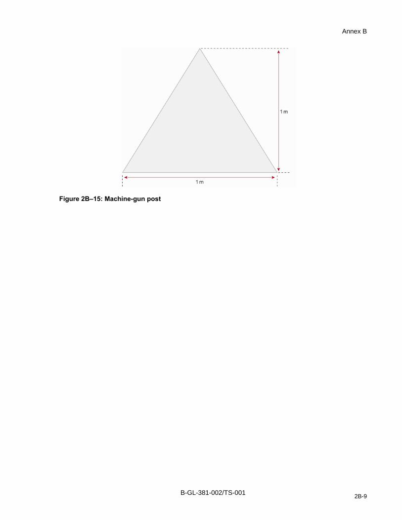
Annex B
Figure 2B–15: Machine-gun post
B-GL-381-002/TS-001 2B-9

Range Construction and Maintenance
Figure 2B–16: Tank pop-up and moving target
B-GL-381-002/TS-001 2B-10
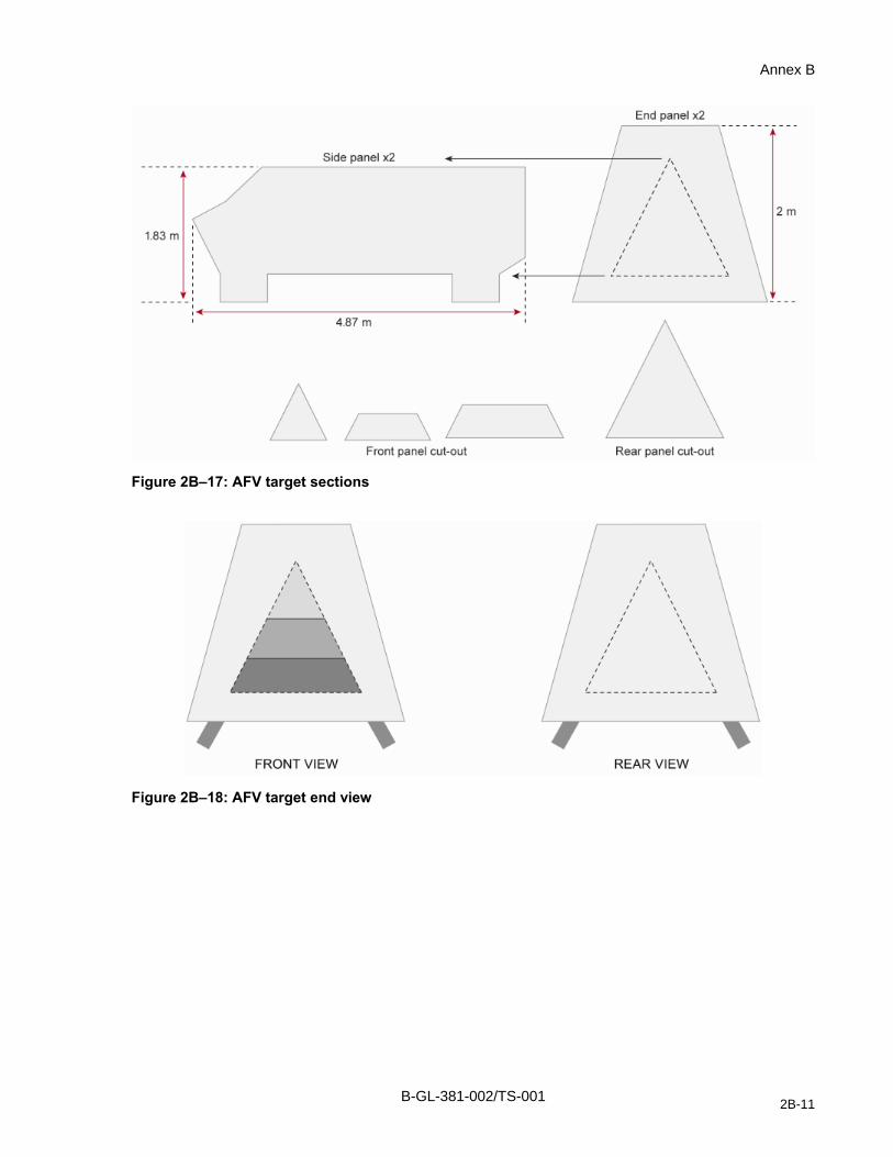
Annex B
Figure 2B–17: AFV target sections
Figure 2B–18: AFV target end view
B-GL-381-002/TS-001 2B-11

Range Construction and Maintenance
Figure 2B–19: AFV target side view
Figure 2B–20: AFV target sectional view
B-GL-381-002/TS-001 2B-12

Range Construction and Maintenance
ANNEX C TO CHAPTER 2 RANGE CONSTRUCTION CONSIDERATIONS
2C01. SETTING UP A RANGE
1. Initial planning for new range facilities must consider the intended training requirements of that area or facility in conjunction with the terrain that is currently available and any future range development plans that may be affected. Terrain must be suitable to match the tactical scenario if any, or the specific weapon, explosives, equipment or vehicle training requirements and consideration must be given to other potential uses or restrictions that may arise. New facilities must also fit within the overall RTA design to prevent potential conflicts with existing facilities (particularly the potential for overlapping danger area templates). Project managers will review the statement of requirement, project proposal, and project design schematics and then conduct a map study using a scaled template of the range. Range design features can then be compared to the terrain contour so that unsuitable sites can be eliminated according to design and site selection criteria. Once prospective site(s) have been identified on the map, future suitability analysis can be accomplished using geospatial technologies combined with on-site inspection. Concurrently, an initial environmental assessment can be conducted using a combination of geospatial applications, archival research and on-site survey. The site may also require a residual risk audit (RRA) if it has been exposed to UXO producing munitions, has been cleared, but where there is a requirement to confirm the current state of UXO contamination. The RRA will provide recommendations to guide any additional clearance operations. Once a site has been deemed suitable, then a formal environmental evaluation of the impact is carried out under the Canadian Environmental Assessment Act.
2. The initial plan should contain information and recommendations covering the following points, bearing in mind the type of range to be constructed and local conditions:
a. the name and CFRIS designation of the range;
b. the GPS coordinates and general description of location of the range;
c. the expected annual training through put and the units that will be using the range;
d. type of range or dangerous area to be designated (Type 1 through Type 4);
e. classification of the range (e.g. conventional, 25 m, field firing, AFV);
f. details of range construction;
g. physical dimensions including width and depth of the range in metres (taken from the firing point furthest away from the targets and including the danger area template;
h. the number and type of target points, target frames, trenches and vertical construction enhancements (in the case of urban facilities) to be provided or are already in existence and their centre line spacing;
i. description of the stop butt (conventional ranges);
j. composition of soil in the butts (e.g. clay, loam, sand);
k. composition of the soil under the butts (clay, loam, sand, shale, etc);
l. number and location of sample wells (to measure lead leaching);
m. length along crest;
B-GL-381-002/TS-001 2C-1

Range Construction and Maintenance
n. thickness at base;
o. above-ground height on the butt;
p. nature and description of the marker’s gallery;
q. where the distance between a stop butt and a target is 25 m or more, an assessment and decision must be made pertaining to the angle of fire from the 25 m point to the targets and the resultant danger area template based on that quadrant elevation to determine suitability to use this space as a 25 m pistol range or for close engagement instinctive shooting with the 5.56 mm;
r. design of firing points, firing pads or gun positions;
s. access roads, gates, control measures and signs;
t. the communication system to be used; in the case of the telephone, cables on all ranges should be buried; and
u. inclusion of workshops, target stores, troop shelters, latrines, water supply system and heat and lighting if necessary.
3. When assigning a land weapon system danger area template to a planned range facility, range designers shall utilize the specific weapon and ammunition templates available within the Computer Aided Range Safety Map (CARSM) program. This is the only recognized template for use in gaining a range license. For MARCOM weapon systems and air to ground munitions delivery, the appropriate danger area template shall be applied and authorized by the ECS responsible for training. Additional considerations pertaining to danger area templates shall include:
a. a list of all weapons intended to be used on the proposed range;
b. a list of all munitions intended to be used on the proposed range;
c. the likelihood of UXO contamination;
d. the maximum length and width of the danger area including the ground in front of and behind the targets or impact area. In all cases the danger area boundaries shall be marked on the range design and accompanying license submission;
e. ground features behind the targets which could eliminate or reduce the size and extent of the danger area;
f. ground features in front of the targets and slope of ground in relation to the targets;
g. the danger area shall be free of infrastructure and civilian personnel;
h. the need to construct new roads to provide access to the ranges; and
i. position of sentries, flags, notices, etc., should be marked on a map.
4. Project managers must confirm that the proposed range construction is to take place on land which is owned or leased by DND. Project managers must also confirm the locations and status of adjoining non-DND properties, public roads or access rights, right of way, and the potential for noise and smoke/dusk exposure to the public:
a. The need to divert or stop traffic.
b. Existing private use of land and land rights (grazing, haymaking, etc…).
B-GL-381-002/TS-001 2C-2
Annex C
c. If land needs to be purchased or leased, certain details have to be obtained such as the probable cost per acre, the names of the owners and the nature of their tenure. The possibility of purchasing or renting it or simply obtaining firing rights should be considered. If the intent is to use UXO producing munitions, then proposed range development shall not take place on leased lands that have never been exposed to UXO producing munitions (i.e. if it is free of UXO, it shall remain in that condition). New properties shall not be purchased or leased for the intended purpose of establishing UXO producing ranges or impact areas.
5. Inquiries concerning land lease or acquisition shall be made in such a way as not to commit DND. Land acquisition must be coordinated carefully and include all relevant Directorates.
6. Project managers will develop multiple viable options for land acquisition and identify the preferred option.
7. Local land managers shall submit land acquisition requirements and plans through their chain of command to their respective ECS for review and approval.
8. It will be necessary to conduct an inspection anytime that a range has been newly constructed or has been modernized. The inspection shall be performed by a qualified Ranges and Training Area Inspector (RTAI), together with the Base/Wing/Station or Camp Range Control Officer and a representative from the Construction Engineer office. The inspection shall certify that the range is safe and is being maintained in a satisfactory condition. A proposal for a range license may be initiated after the inspection through the LFDTS HQ DAT CFRIS manager.
9. No CF range shall be authorized to function until such time that it has been inspected, certified and a license has been authorized within CFRIS. All relevant data pertaining to the range must be entered and maintained for the lifetime of that facility. The current status of the range, including all inspection reports and usage report data, shall be maintained within the CFRIS database.
2C02. OPERATIONAL REQUIREMENT
1. Under Parliamentary authority, the CF is granted provisions for the establishment of military training facilities for use in maintaining our operational capability. This capability is built on a foundation of a high standard of individual and collective training that is the key enabler to meeting our assigned missions and tasks. The broad spectrum of training tasks that ultimately enable the projection of the national will through the use of lethal force is maintained through the exclusive use of designated installations and the ranges and training areas they contain for the express purpose of military training and testing. The CF therefore has a legal and moral responsibility to protect military personnel undergoing training through effective land management and safety policies. It also has equal responsibility to protect the general public through effective access control and by imposing limits and restrictions on the use of military property. DND P56 articulates CF policy for public access and provisions of safety for the public.
2. The existing CF inventory of RTA must be continuously assessed for suitability so as to determine the need to acquire additional lands to meet training demand, or to divest surplus lands from the Departmental inventory when these are no longer suitable for military training. Every effort must be made to maximize the use of available land and minimize demands for new lands. The future requirement for ranges and training areas cannot be foreseen in detail; therefore proper land management practices will extend the life of each facility and avoid contamination of the land.
B-GL-381-002/TS-001 2C-3


Range Construction and Maintenance
ANNEX D TO CHAPTER 2
2D01. RANGE SIGNS
1. Range boundary signs are approximately 30 cm by 40 cm. The order number is NSN-9905-21-562-6460.
2. Figure D–1 is an example of a basic range boundary sign.
Figure 2D–1: Range boundary
2D02. NO TRESPASSING SIGNS
1. These signs are approximately 40 cm by 60 cm.
2. Signs NSN-9905-21-562-6456 (French) and NSN-9950-21-562-6457 (English) are available through the supply system. Signs may be produced locally. These signs are shown in Figures D–3 to D–5.
2D03. BARRIERS AND BARRIER SIGNS
1. Any road that enters a RTA dangerous area shall be guarded by a barrier or gate which must remain closed during all training or firing practices. All access points, including barriers and gates, shall display a sign such as that illustrated in Figure D–2/D–3. A barrier warning sign shall also be posted sufficiently ahead of the barrier to ensure the driver can stop (Figure D–4) Also required is a STOP sign on the barrier (not shown).
B-GL-381-002/TS-001 2D-1

Range Construction and Maintenance
Figure 2D–2: Keep out sign
Figure 2D–3: Défense de passer
B-GL-381-002/TS-001 2D-2

Annex D
Figure 2D–4: Barrier sign
Figure 2D–5: No live ammunition or explosives are permitted in this room
B-GL-381-002/TS-001 2D-3


Range Construction and Maintenance
ANNEX E TO CHAPTER 2
2E01. ENVIRONMENTAL REFERENCES APPLICABLE TO RTA
1. Federal Environmental Legislation:
a. Canadian Environmental Protection Act (1999) and Regulations;
b. Canadian Environmental Assessment Act and Regulations;
c. Fisheries Act;
d. Migratory Birds Convention Act (1994);
e. Canada Wildlife Act (1985);
f. Transportation of Dangerous Goods Act (1992);
g. Species At Risk Act; and
h. Toxic Substances List.
2. Environmental Policies:
a. Wetlands Conservation Policy;
b. Policy for the Management of Fish Habitat; and
c. Forest Management Policy.
3. Environmental directives governing firing range construction and maintenance:
a. NDHQ/CF Sustainable Development Strategy;
b. Land Force Command’s Environmental Management System, 2005;
c. Base/unit Environmental Management Systems;
d. DAOD 2008–3 Issue and Crisis Management;
e. DAOD 4003–0 Environmental Protection and Stewardship;
f. DAOD 4003–1 Hazardous Materials Management;
g. DAOD 4003–2 Environmental Assessment;
h. DAOD 4007–0 Fire Protection Services.
4. ADM(IE) Environmental Directives:
a. ED 4003–1/2003 Spill Reporting;
b. ED 4003–02 Management of Storage Tank Systems for Petroleum and Allied Petroleum Products;
c. ED 4003–03 Management of Contaminated Sites (to be published);
d. ED 4003–4/07 To Reduce the Use of Pesticides on DND Properties;
e. ED 4003–05 Halocarbon Management;
f. ED 4003–07 Management and Monitoring of Liquid Effluents;
g. ED 4003–06 Forest management policy (to be published);
h. ED 4003–9 Hazardous Materials Management Plan;
i. Chap 2–15 Pesticides Directive
B-GL-381-002/TS-001 2E-1

Range Construction and Maintenance
j. Treasury Board Federal Contaminated Sites and Solid Waste Landfills Inventory Policy.
B-GL-381-002/TS-001 2E-2

Range Construction and Maintenance
CHAPTER 3 DIRECT FIRE RANGES
SECTION 1 INTRODUCTION
301. GENERAL
1. This chapter provides information to assist in the planning of new ranges or the verification of existing range designs. Guidance is provided to select RTA sites that will optimize utilization potential while meeting established safety standards. Specifications may be articulated where it is necessary to establish the size of the site appropriate for a particular range. These specifications may be used to assess the design requirements or the status of existing facilities such as stop butt that have been exposed to weather and erosion. DND/CF engineering standards, guidelines and criteria for permanent range facilities and vertical construction are available from Director Realty Asset Plans (DRAP) at NDHQ, which is part of Director General Realty Policy and Plans (DGRPP).
SECTION 2 COMMON FEATURES OF DIRECT-FIRE RANGES
302. GENERAL
1. Many direct-fire range facilities will incorporate common design features that alleviate the time and expense that might otherwise be incurred for custom applications. These common features are provided as a guide and may be modified to meet the specific needs of a particular range. Listed below are some of the more common design features found in land-based RTA facilities.
2. Outdoor ranges provide a realistic training environment which replicates the terrain and environmental conditions that will exist during operations. Range capabilities include the use of long-range weaponry, coordinated fire effects including fire and manoeuvre, the use of explosives and a variety of stationary and automated target systems.
303. TARGETS
1. Chapter 1 of this manual provides direction on the variety of targets that may be employed on direct-fire ranges.
304. SITE SELECTION
1. If possible, the ground selected for a range should meet the following selection criteria:
a. firm, level and well drained, providing direct line of sight from the firing point to the intended target location;
b. free of obstructions and hard materials which could cause ricochets;
c. located near existing road network;
d. located near electrical power distribution system (if facilities include electronic equipment, lights etc);
e. located away from sensitive areas;
f. large enough to accommodate the current danger area templates and larger, if possible, in order to accommodate future munitions; and
B-GL-381-002/TS-001 3-1

Range Construction and Maintenance
g. facing north/south if possible.
305. RANGE BOUNDARIES AND SIGNAGE
1. Chapter 1 of this manual gives direction on access control measures, signage and marking of ranges and range boundaries.
SECTION 3 15 METER CONVENTIONAL RANGE
306. GENERAL
1. Construction parameters for 15 m outdoor ranges are contained within CETO C-98-010-001-DD-004. Although dated, this publication provides the necessary specifications to construct a short distance conventional range suitable for pistol, rifle and carbine fire (including modern SMGs such as the 9 mm MP5).
SECTION 4 25 METER CONVENTIONAL RANGE WITH NO DANGER AREA
307. LOCATION
1. There is an ongoing requirement to conduct personal weapon qualification and instinctive quick-shot close range qualification training in areas that are conveniently located. These facilities must be carefully sited and designed to minimize the possible negative effects of noise and lead contamination. As a minimum, 25 meter conventional ranges shall be situated no less than 400 m from residential housing, hospitals and other buildings
308. DESIGN
1. Figure 3–1 gives two sectional representations of a 25 m range with no danger area.
309. DATUM LINE
1. The datum line for all elevations corresponds to the top of the target slot.
310. STOP BUTT WALL
1. As shown in Figure 3–1, the minimum height is 5.5 m. If there is no ricochet pit the height shall be 7.3 m. Width will vary with the number of firing positions. The stop butt shall be constructed on top of a concrete footing suitable for the intended weight load. The top surface of the footing shall be covered with an impermeable membrane to prevent lead leaching into the surrounding soil. The stop butt wall shall be constructed to prevent penetration by the intended ammunition.
311. BULLET CATCHER
1. The sand in the bullet catcher must be kept loose, with a mixture of 50/50 sand and sawdust, thoroughly mixed to ensure that no areas are predominantly sand. The top filling shall be spread evenly to a depth of two feet at a slope angle of 605 mils/34 degrees. The fill will be raked level when necessary to prevent tunnelling, erosion and possibility of ricochet. Average penetration should be 30 to 35 cm. Average penetrations of 25 cm or less indicates a high sand content and further mixing is required before putting the range into use.
B-GL-381-002/TS-001 3-2

Direct Fire Ranges
2. The recommended grade of sand for use in the bullet stop is based on the percentage of sand passing through a sieve:
a. Grade 4 ………. 100%;
b. Grade 10 …….. 95–100%; and
c. Grade 200 ……..0–.10%.
3. The concrete walls of the bullet catcher shall be faced with a minimum 7.5 cm thickness of pressure treated wood with a 5 cm air void, which will reduce ricochet and backsplash. A length of timber should also be fixed to the bullet catcher base.
312. MAINTENANCE
1. Sand and clay bullet catchers or stop butt shall be sanitized when bullet penetration is less than 25 cm or when results of as a site specific environmental monitoring and assessments of risk indicate a requirement for action.
2. The local Environmental Officer shall assess the risk posed by each stop butt with the implementation of a standardized sampling protocol and risk assessment process defined in the LFC EMS.
Figure 3–1: 25 metre range with no danger area template
B-GL-381-002/TS-001 3-3

Range Construction and Maintenance
Figure 3–2: Example photo showing a 25 yard range with no danger area
313. TARGET SLOT
1. This should be located immediately in front of the bullet catcher. The bullet catcher must extend 1.25 m beyond each end of the target slot. Figure 3–1 shows the 1.25 m space.
314. TARGET TRENCH
1. The target trench may be located to accommodate a mechanical target mechanism. The target trench dimensions must be adequate to provide protection against bullet strike to the target mechanism. The length will equal that of the target slot.
315. RICOCHET PIT
1. The ricochet pit shall slope from the 25 m firing point to the target trench, reaching a depth of 2 m.
2. The surface of the pit should be grass covered, or covered with sand and must be free from stones, cement or metal which may cause ricochets.
3. A wooden staircase should be constructed to allow access to the targets from the ricochet pit. The staircase should be located outside the arcs of fire. The materials used in the construction of a staircase must not pose a ricochet hazard.
316. FIRING POINTS
1. A fire trench may be constructed at the 25 m point. This would allow firing in all but the prone position.
B-GL-381-002/TS-001 3-4

Direct Fire Ranges
2. Each firing position should be grass covered. Firing points must be at least 3 m long for prone position firing. The distance between firing positions shall adhere to the following specifications:
a. rifle, carbine, shot gun and pistol firing points shall be separated by no less than 1.5 m;
b. light machine-gun points shall be separated by no less than 2 m;
c. sub-machine-gun and MP5 firing points shall be separated by no less than 3.5 m;
d. general purpose machine-gun in the light role shall be separated by no less than 4 m; and
e. 84 mm anti-tank guns using 7.62 mm gallery ammunition shall be separated by no less than 4 m.
3. A level, 2 m long step should b located at the 20 m and 15 m firing points. The front edge of the step must be the required distance from the targets.
317. WING WALLS
1. Angular wing walls set at an angle of 36o, as depicted in Figure 3–1, shall extend 6.7 m beyond the stop butt. Wing walls shall be covered with a minimum of 7.5 cm thickness of pressure treated wood with a 5 cm air void to reduce ricochet and backsplash.
2. When two 25 m ranges are constructed back to back, the wing walls will retain their offset angles. Wing walls shall be covered with a minimum of 7.5 cm thickness of pressure treated wood with a 5 cm air void to reduce ricochet and backsplash.
318. POSITION OF TARGETS
1. Target placement shall ensure shot placement against the bullet stop. A target slot and a target trench should be provided that can accommodate all current targets. The practice of placing targets at various heights must be carefully considered to avoid high, poorly placed shots that may be directed over the stop butt wall.
2. No target shall be positioned within 1.25 m of either end of the stop butt. The stop butt must catch all rounds which pass through the target considering each position and distance.
SECTION 5 25 METER CONVENTIONAL RANGE WITH DANGER AREA
319. GENERAL
1. When it is not possible to construct a stop butt with wing walls as depicted above, the 25 m range must include a danger area appropriate for all intended weapons and ammunition types. The danger area shall extend from the closest firing line to beyond the target line according to the approved template. B-GL-381-001/TS-000 Training Safety contains a complete list of danger area templates and safety requirements. Approved templates are available through CARSM.
2. With the exception of the stop butt design and danger area requirements, the design criteria outlined for the 25 m outdoor range with no danger area applies.
B-GL-381-002/TS-001 3-5

Range Construction and Maintenance
320. STOP BUTT
1. Stop butt are required to control the spread of lead contamination and to prevent ricochet. As a minimum, the dimensions for a stop butt for a 25 m conventional range with a danger area are 3 m high, extending 2 m beyond the flank targets.
2. When a natural stop butt such as a vertical cliff, a sand quarry or a wall with the required dimensions is available, a range can be constructed at reduced cost. Ranges that rely on natural features to act as a bullet stop should include a ricochet pit. Where a ricochet pit is not possible or practical, then the total elevation of the natural feature shall be raised to a height sufficient to ensure bullet capture. Total height and slope requirements are as follows:
a. When the angle of the slope is not more than 180 mils (10°) from the vertical, the height shall be 6.7 m with a ricochet pit or 9.1 m without a ricochet pit. See Figure 3–1.
b. If the slope is not more than 533 mils (30°) from the vertical, the height shall be 9.1 m with a ricochet pit and 12.2 m without one.
3. Stop butt maintenance shall be the same as above.
SECTION 6 CONVENTIONAL RANGES
321. DEFINITION
1. Conventional ranges are designed specifically for the conduct of marksmanship training and crew served weapon qualification. A conventional range is constructed as a permanent facility with fixed firing points along a fixed firing axis. Small arms conventional ranges normally feature a marker’s gallery, butt stop, target mechanisms and frames or automated target system and includes ancillary buildings (ablutions, range hut, target shed, etc.). Range design is intended to maximize shooter throughput by incorporating multiple firing lanes. Conventional ranges use a standard layout which is suitable for formal training and qualification on CF weapons to meet extant training policy. Small arms conventional ranges may be configured as:
2. 400 m conventional ranges utilize an 89 mil quadrant elevation (QE) template to permit the conduct of marksmanship training and the completion of annual personal weapon tests (PWT). The 400 m conventional range features raised firing points at 100 m intervals out to 400 m and is suitable for training and testing with all in-service 7.62 mm and 5.56 mm calibre rifles, carbines and the conduct of preliminary practices for the light machine-gun (LMG). Target engagement may also occur forward of the 100 m firing point at 75 m, 50 m and 25 m ranges. Range design must factor any restrictions imposed by the danger area template and conform to the maximum elevation (89 mils) when engaging targets at the forward firing point.
3. 600 m conventional ranges utilize an 89 mils QE template and are suitable for the conduct of preliminary practices and the conduct of annual PWT for gun crews in the light role using the 7.62 mm GPMG and for gunners assigned the 5.56 mm LMG as a personal weapon. This range is designed with raised firing points commencing at 100 m and continuing in 100 m intervals to the 600 m firing point. Range layout must consider the larger beaten zone inherent with machine-gun fire.
4. 1000 m conventional ranges utilize an 89 mils QE template and are suitable for the conduct of preliminary training and annual PWT for gun crews in the sustained fire role on the 7.62 mm GPMG and sniper rifle. Designed with raised firing points at 100 m intervals, range layout must consider the larger beaten zone inherent with machine-gun fire and the greater penetration when firing the .50 calibre round.
B-GL-381-002/TS-001 3-6

Direct Fire Ranges
322. FIRING PLANE
1. Conventional ranges should be constructed on level ground to assure an accurate trajectory across a level line of sight. As a general rule, any elevation between the firing point and target line, and corresponding line of sight, will increase the height of the Mean Point of Impact (MPI) and result in a greater frequency and range of ricochets. It is important therefore, to confirm the natural elevation of the ground and the line of sight by conducting a survey to accurately predict the maximum height and distance of the aiming point.
323. DETERMINING THE DIMENSIONS OF THE DANGER AREA
1. Conventional ranges shall employ the 89 mils QE danger area template for the ammunition and weapons intended to be used. The application of a danger area template will start by confirming that the range line of sight between the firing line and target line is level. Then the appropriate template and QE shall be applied from those in B-GL-381-001/TS-000 Training Safety or CARSM appropriate for the intended use of the range. In the following example, 5.56 mm ball ammunition will be used with a maximum QE of 89 mils/5 degrees.
2. The danger area will commence from the most advanced firing point (closest to the target) and extends beyond the stop butt over a distance of 2,400 m from the target line.
3. The total template width for any multiple of firing points is then calculated by adding the width of all firing lanes, subtract one lane (representing the value of outside space of separation) and the multiply by 4 m. The resultant figure is the total template width. Table 3–5 demonstrates a width based on the number of firers.
4. An additional 200 m is applied to the overall width of the firing lanes on each side for the first 300 m of the danger area, starting at the most advanced firing point (25 m or 100 m). (See Figure 3–3). The next step is to draw a straight line linking the following points: 1800 m beyond the target line and 350 m outside the firing lanes. For the last 600 m of the danger area the total width outside the firing lanes must be reduced to 250 m.
5. Once the danger area is established there should be no buildings, roads or pathways in this area. If roads or pathways do cross the danger area then it is necessary to establish access control to close the route during firing practices.
B-GL-381-002/TS-001 3-7

Range Construction and Maintenance
Figure 3–3: Conventional range template, 5.56 mm
B-GL-381-002/TS-001 3-8

Direct Fire Ranges
Figure 3–4: Conventional range template 7.62 mm
B-GL-381-002/TS-001 3-9

Range Construction and Maintenance
Figure 3–5: Dimensions of danger area for a 5.56 mm conventional range
324. ADJOINING RANGES
1. If there is a requirement to minimize the overall size of a danger area, then the maximum reduction of the danger area can be achieved by aligning the firing axis of two or more ranges so that the danger area overlays coincide. This positioning and alignment of ranges can be accomplished by applying the appropriate templates in CARSM. If done during the planning stage, then project managers will be able to determine the positioning of the adjoining range to achieve coincidence.
B-GL-381-002/TS-001 3-10

Direct Fire Ranges
Figure 3–6: Danger areas for adjoining ranges
325. PARALLEL RANGES
1. A reduction in the space required for the danger area of parallel ranges can be achieved by applying the danger area overlays of both ranges and noting which firing points lie outside the overlay of the parallel range. If the result is 300 m, then an entry may be made in the Range Standing Orders to permit the use of these firing points simultaneously where they are separated by a distance of 300 m. At the planning stage, if parallel ranges are to be set up these must be positioned with the required distance between them to permit simultaneous use as illustrated in Figure 3–6.
326. REDUCTION IN DANGER AREA
1. A reduction in the size of the danger area may be considered when there is a steep hill immediately behind the target line. If the hill rises vertically, or with not less than a 3:2 slope (angle of 1000 mils/56 degrees) in relation to the horizontal, to a height of at least 45 m above the line of sight, then no danger area is required beyond that line.
2. When a reduction in a weapon danger area is warranted according to the criteria stated above, the requesting unit shall submit a risk analysis through the chain of command to LFDTS HQ attention DAT RTAM. DAT RTAM and DAT Training Safety shall review the risk analysis prior to referral to ADM(Mat) DAEME who will complete a technical review and make a recommendation of risk acceptance to the CLS. The CLS shall render a decision to accept the risk and advise DAEME of the requirement for production of a reduced danger area template. Weapon danger area templates for air and naval weapons remain the responsibility of the ECS.
B-GL-381-002/TS-001 3-11

Range Construction and Maintenance
327. STOP BUTT
1. A conventional range will always have a stop butt behind the target line to capture bullets and prevent ricochet. The stop butt ensures that the bullet is captured well short of its potential maximum ricochet range to prevent the widespread distribution of heavy metals and to ensure the safety of personnel beyond the limits of the range facility. The stop butt also serves to allow the target markers to observe bullet impact into the sand as an aid in target indication. The bullet splash against the stop butt also aids the firing point coach or the Assistant Range Safety Officer (ARSO) to report point of impact to the shooter to allow corrections in sight adjustment and/or point of aim.
2. Material. Construction materials for stop butt will generally consist of sand and clay. The soil will be mounded to form a steep bank immediately behind and rising above the target line a short distance from the marker’s gallery (if so equipped). Construction materials must be free of stone or other hard objects that pose a ricochet hazard. Design of a conventional range stop butt shall meet the following specifications:
a. Height. The highest point or crest of the stop butt mound shall rise no less than 1.2 m above the line of sight measured from the top of the target, in the case of 1.8 m targets, to the crest of the mound regardless of the firing position.
b. Length. The length of the crest of the stop butt is dependant on the number of targets installed. The crest must extend no less than 6 m beyond the outer edge of the left and right flank targets. For example, a 20 lane range will require a stop butt crest length of no less than 92 m. (e.g. 20 x 4 m + 12 m).
c. Thickness. The crest line of the stop butt must be level and no less than 1.5 m thick. The thickness of the stop butt base will depend on the required slope of the forward face.
d. Density. The compactness of the sand and clay mixture (or other local soils) must be carefully managed through regular maintenance and raking to ensure sufficient penetration to a depth of 25 to 30 cm. Care must be taken in the winter months to ensure that there is no ricochet danger posed as a result of moister saturation and freezing.
e. Base. The stop butt mound shall be constructed atop an impermeable barrier of synthetic sheeting or clay to reduce the risk of contamination from lead leachate. A berm shall be constructed 1 m in front of the base extending to the stop butt flanks where to terminate in holding ponds lined with impermeable clay. The holding pond shall be of sufficient depth to allow the settlement of heavy metals suspended in rain water runoff to permit evaporation of potentially contaminated water. The holding pond must prevent water mobility and absorption into the surrounding soil where there is a risk to ground water sources.
B-GL-381-002/TS-001 3-12

Direct Fire Ranges
Figure 3–7: Interim conventional range layout
Figure 3–8: Stop Butt
B-GL-381-002/TS-001 3-13

Range Construction and Maintenance
Figure 3–9: Bullet catcher
f. Slope. The forward slope of the stop butt shall not be less than 605 mils/34 degrees in relation to the horizontal plane. Right angle brackets may be placed on the slope to preserve the angle. The slope at the ends of the stop butt may be at the natural angle of repose of the material used. See Figure 3–8.
g. Position in Relation to Targets. The distance between the targets and the stop butt can vary with the material used. When the stop butt consists of sand and clay, with no stones or rocks, it may be positioned less than 5 m from the targets. If there is any risk of backsplash then the distance shall then be at least 30 m.
h. Bullet Catcher. A stop butt shall incorporate bullet catchers to limit the ejection of bullet fragments and soil. Bullet catchers shall be 3.5 m wide by 3.5 m high as illustrated in Figure 3–9. Bullet catchers shall be covered with water resistant fabric to reduce erosion from rain and snow runoff. Bullet catchers may also be free standing and positioned directly behind the target frame for ranges that do not require a marker’s gallery (e.g. Automated Target Systems). The bullet catcher serves to capture the bullet to reduce stop butt maintenance.
328. RANGE MAINTENANCE
1. Regular maintenance of conventional ranges is necessary to assure a safe training environment for all personnel engaged in firing practices. Regular maintenance reduces the risk of tripping and falling while engaged in live-fire practices. Semi-annual inspections and maintenance will also reduce the occurrence of ricochet that results from soil compaction and the degradation of the stop butt and other range infrastructure that can pose hazards to health and safety. Regular maintenance also ensures DND compliance with environmental regulations in preventing the uncontrolled erosion of contaminated soil that could pose a risk to ground water. Prolonged firing will result in the build-up and spread of bullet fragments and contaminated soils.
2. Stop butt raking. The stop butt shall be maintained monthly by raking the soil to preserve the 34o frontal slope, and the crest and flanks IAW specifications. Raking is necessary to maintain soil consistency to allow full penetration of projectiles and to minimize soil compaction and tunnelling at the site of bullet impact. Soil that is ejected from the point of impact or is carried down the front slope by rain water and melting snow must not be allowed to wash into local water sources or to contaminate the markers’ gallery. Maintenance crews may
B-GL-381-002/TS-001 3-14

Direct Fire Ranges
collect washed out soil to be added to new soil for use in repairing bullet damage or this ejected material may be discarded IAW approved methods.
3. Stop butt tunnelling. Tunnelling is caused by the repeated impact of bullets in a concentrated area resulting in the ejection of stop butt materials and the formation of deep depressions. The resultant deformation of the stop butt shape will alter the ricochet trajectories and if left unchecked will eventually pose a safety hazard in the markers’ gallery and to the flanks of the range. The stop butt shall be repaired when the slope along the edges of the tunnelling site depression is plus or minus one or more degrees from the standard slope of 34 degrees and at any time when bullet penetration is less than 25 cm. Immediate repairs are necessary any time that bullet materials are concentrated at the surface resulting in the dispersal of bullet fragments and contaminated soil beyond the stop butt.
4. Vegetation. Grass and weeds on the firing lanes and stop butt shall not exceed 10 cm in any area of foot traffic, particularly on and between the firing points. Seedlings and noxious weeds shall be cut or removed or controlled through the use of approved herbicides.
5. Firing points. Firing points shall be raked and/or filled with soil as needed to maintain a 5 degree slope. Debris, brass casings and links (if machine-guns are approved) shall be cleared at the conclusion of each training event Land indicator stakes shall be painted, numbered and affixed firmly into the ground. If necessary, grass seed shall be applied annually.
6. Bullet catchers. The wooden frames of bullet catchers shall be inspected no less than annually to determine their state of deterioration. The wooden frame shall be replaced when its structural integrity can not contain the soil filler. The fabric cover shall be replaced when it no longer contains bullet splash or runoff.
329. REMEDIATION
1. Stop butt remediation (soil replacement) shall be undertaken when bullet penetration within the bullet catchers is less than 25 cm or when results of as a result of site specific environmental monitoring and assessments of risk indicate a requirement for action.
2. The local Environmental Officer shall assess risk posed by each stop butt with the implementation of a standardized sampling protocol and risk assessment process defined in the LFC Environmental Management System. Factors to be assessed include, but are not limited to:
a. frequency of use;
b. range location and geographic region;
c. soil type and permeability;
d. annual rainfall;
e. ecologically sensitive areas;
f. distance to groundwater;
g. risk exposure due to contaminated soils;
h. distance to surface water;
i. risk exposure due to contaminated groundwater / surface water;
j. age of the small arms range; and
k. stop butt risk exposure due to clean up practices.
B-GL-381-002/TS-001 3-15

Range Construction and Maintenance
330. TARGET NUMBERS
1. Target numbers shall be constructed of wood or other material that does not pose a ricochet hazard. Target number support frames shall be mounted to the rear of the number surface so that no metal fasteners (bolts, nails etc) are exposed.
2. Targets shall be numbered from the left to the right to ensure consistency in the reporting of range usage and lane bullet counts. Target numbers shall be positioned along the crest of the stop butt aligned with the firing position and target.
3. Target numbers shall be no less than 1.5 m square and painted in alternating colours to ensure a clear contrast with the adjacent target number and the range background. A recommended colouring scheme is as follows:
a. Target No. 1: black;
b. Target No. 2: yellow;
c. Target No. 3: red; and
d. remainder of targets are coloured sequentially in this repeating pattern.
4. Maintenance of target numbers shall ensure that the surface is clearly legible from all firing points, that the numbers of ricochet hits do not diminish the structural integrity of the target number surface or frame and that there is no risk of injury in the marker’s gallery from backsplash or flying splinters.
B-GL-381-002/TS-001 3-16

Direct Fire Ranges
Figure 3–10: Marker’s gallery (Concrete)
NOTE Drainage tiles are to be located at the base of the footing
331. MARKER’S GALLERY
1. Figure 3–10 illustrates a typical marker’s gallery suitable for a conventional range employing the Hythe target lifters. The following criteria shall be met:
a. The layout of the marker’s gallery must be at a 90 degree angle to the axis of the range. Further, the marker’s gallery and the stop butt must be parallel to ensure a direct angle of impact from rounds fired.
b. Frontal protection shall be a minimum of 1.5 m comprising no less than 23 cm reinforced concrete and 1.25 m of packed soil in the mantlet mound. Overhead protection must be provided to ensure the safety of the markers.
c. Overhead protection shall be a minimum of 8 cm reinforced concrete.
d. The marker’s gallery overhead protection shall slope slightly downward towards the targets (slope of 90 mils / 5 degrees) to prevent any ricochet off the roof surface from bouncing upward to strike the target.
e. The internal dimensions of the marker’s gallery roof shall be no less than 1.95 m high to allow personnel to stand up inside. The marker’s gallery shall be no less than 1.1 m in depth and extend for the entire width of the target frames with a 5 degree downward slope towards the target to facilitate drainage. The marker’s gallery shall be constructed of reinforced concrete, no less than 8 cm thick and covered with 15 cm of earth with adequate support beams affixed.
f. The markers must be able to observe the impact of bullets into the stop butt to aid in target indication.
g. All targets shall be clearly visible from all firing positions. See Figure 3–10.
B-GL-381-002/TS-001 3-17

Range Construction and Maintenance
h. When the ground between the farthest firing point and the marker’s gallery is level, the marker’s gallery may be constructed either above or below ground level. This also applies when there is a slight downward slope from the firing point to the stop butt. If the line of sight is uphill towards the marker’s gallery, thus increasing the ricochet distances, then the marker’s gallery should be constructed below ground. Local conditions shall be considered to ensure proper drainage and safety.
i. A small bench seat shall be fixed against the back of the gallery wall.
j. A phone connection and mounting point shall be installed near the centre of the marker’s gallery on the back wall.
332. MANTLET
1. The purpose of the mantlet is to provide frontal protection for the marker’s gallery and to reduce the number of ricochets from low shots. The mantlet shall be constructed with a minimum of 1.5 m of earth at its crest sloping downward to its base at 34 degrees. See Figures 3–10 and 3–11.
Figure 3–11: Formation of scoops on mantlet
2. The top of the mantlet must not be less than 8 cm below the bottom of the targets when these are in the correct position for firing. It may be necessary to increase this distance if the line of sight is slightly uphill, so that a gap between the target and the mantlet can be seen from all firing positions. See Figure 3–11.
3. The front slope of the mantlet must be a minimum of 605 mils/34 degrees in relation to the horizontal from the ground to the top.
4. The top of the mantlet shall be marked off with a 6 x 6 inch or two 2 x 10 inch stakes to maintain the correct height and width of the crest. This prevents the formation of scoops (Figure 3–11) that pose a risk of ricochets in all directions and creates the potential for bullets to penetrate into the gallery.
333. TARGET FRAME
1. The most common form of target frame currently in use on conventional ranges is the Hythe type, as shown in Figures 3–12 and 3–13. The Hythe target frame is constructed of steel and comes as a complete unit ready to be installed.
B-GL-381-002/TS-001 3-18

Direct Fire Ranges
2. The Hythe target frame shall be fastened to the marker’s gallery floor, aligned to the firing point and no less than 2.1 m beyond the gallery wall and the markers’ seats.
3. No part of the metal surfaces of the target frame shall pose a ricochet hazard with the upper most frame surface remaining below the line of sight.
334. FIRING POINTS
1. Firing points on conventional ranges shall be positioned in 100 m intervals commencing at the 100 m point and extending to the maximum firing line of that range. Firing points shall also be installed at the 25 m, 50 m and 75 m ranges to facilitate close quarter firing and the PWT. Care must be taken to verify that the angle of fire from the closest firing point to the target line does not exceed the QE of the danger area template for that range.
2. Firing points shall be perpendicular to the centre line of the range.
3. The firing points may be constructed at ground level where local terrain and environmental conditions permit. Low mounds may be constructed where the ground is hollow or swampy or to allow rainwater to run off. Elevated firing points should be angled in a downwards slope to maintain proper angle of fire towards the target area.
4. Firing points shall conform to the following dimensions:
a. width—4 m apart from the centre;
b. length—3 m to permit firing from the prone position; and
c. slope—89 mils/5 degrees, front higher than the rear.
5. Firing positions may be constructed of earth or a mix of sand and clay and shall be free of rocks or any hard substance that could cause ricochets. Where there is a risk to ground water from lead particulate suspended in rain water, then crushed limestone may be added to the soil. Grass shall provide a good surface for a firing point.
6. A wooden stake shall be installed adjacent to each firing point to indicate the firing lane. Stake colours shall match the applicable target number.
7. A range distance sign shall be installed at a flank of the firing line to indicate the range distance; and
8. A range flag post holder/frame shall be installed at a flank of the firing line.
335. COMMUNICATIONS
1. The Officer in Charge of the Practice (OIC) must be able to maintain positive communications with the marker’s gallery, the range gate, all sentries and range control. It is most important that all conventional ranges be equipped with a practical and efficient communication system. This may include land line and phone or a combination of phone and radio communications.
336. REMOTE CONTROL TARGETS
1. Conventional ranges may be suitable for the use of remote control/automated targetry without major structural changes being necessary.
2. Figure 3–14 illustrates a method to modify an existing conventional range to incorporate remote control targets. The existing mantlet is extended and a ditch is added along the crest in which to set the target mechanisms. The ditch is constructed of concrete at its base and an
B-GL-381-002/TS-001 3-19

Range Construction and Maintenance
additional drainage system is included. A protective cover should be installed over the target ditch to shield it.
3. An automated targetry system may also be incorporated into existing conventional ranges. Given similar modifications to the mantlet as for remote control targets, the addition of a bullet catch to the rear of the permanent target sensor will reduce maintenance requirements for the stop butt. The sensor array will also require the installation of electrical utilities and system wiring between the target sensor and firing line.
Figure 3–12: Hythe pattern target frame
B-GL-381-002/TS-001 3-20
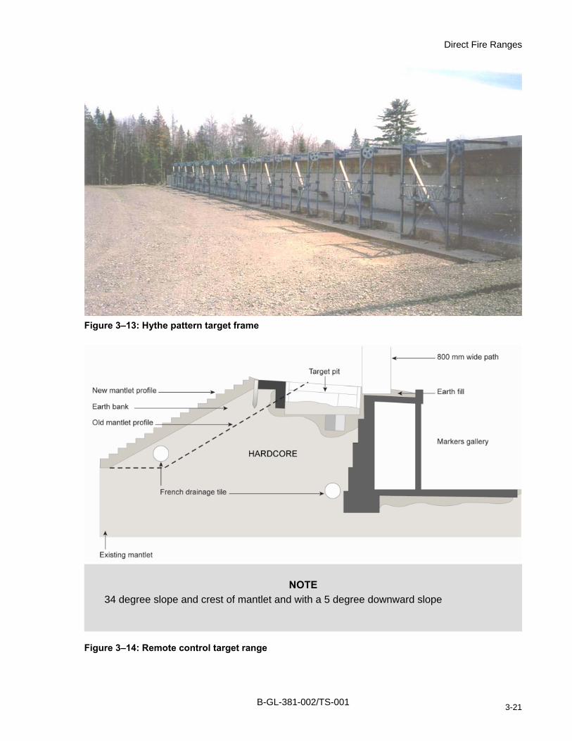
Direct Fire Ranges
Figure 3–13: Hythe pattern target frame
NOTE 34 degree slope and crest of mantlet and with a 5 degree downward slope
Figure 3–14: Remote control target range
B-GL-381-002/TS-001 3-21

Range Construction and Maintenance
SECTION 7 AUSTERE RANGE
337. GENERAL
1. Austere ranges replicate the capabilities of a conventional range, but are simplistic in design, low in cost and of temporary status. Austere ranges must be inspected and certified by a qualified RTAI and be licensed for operation within the CFRIS. All user and ammunition data must be recorded.
2. Normally there is some preparation of the firing points, while a stop butt is deemed to be necessary only when there is a possibility of ricochets. There is usually no hard shelter or latrine, no prepared parking area and no food preparation facility at these ranges. A field firing safety template shall be used to determine the safety parameters.
3. Bullet catchers may be constructed to reduce the possibility of ricochets, to help instructors to determine where the round strikes the target and to assist in the control of lead contamination. A height of 2.5 m is acceptable according to the condition of the ground. See Figure 3–15 and Figure 3–16.
338. MAINTENANCE
1. Austere ranges may not be subject to the day to day management of a parent range control element, however, when in use, austere ranges shall be maintained and inspected the same as any conventional range.
339. SAFETY
1. Austere ranges shall use a 200 mil QE template for the ammunition to be fired. Austere ranges must consider all potential safety hazards and may require the publication of Notice to Airmen (NOTAM) prior to the conduct of a range practice if near a flight corridor.
340. SIGNS
1. Austere ranges that do not have permanent perimeter fencing and the normal DND signage required of a conventional range, shall be required to post warning flags and use ground/air/water sentries at all points of exit into the danger area.
B-GL-381-002/TS-001 3-22

Direct Fire Ranges
Figure 3–15: Typical stop butt of an austere range
Figure 3–16: Natural stop butt of an austere range
B-GL-381-002/TS-001 3-23

Range Construction and Maintenance
SECTION 8 BAFFLE RANGES
341. GENERAL
1. Baffle ranges are intended to meet small arms training requirements in locations where it is not possible to apply a full danger area template. It may be possible to construct a range that utilizes a series of overhead deflectors to eliminate the potential escape of errant rounds or ricochet using a series of overhead baffles. A baffle range may provide a reasonable option to permit small arms firing in areas adjacent to other personnel and infrastructure. Baffle ranges are normally designed for ranges of 200 m to 300 m, but may be longer if resources and space permit.
342. SITE
1. The installation of a baffle range must be balanced with the need to manage noise and to control the potential spread of lead contamination.
343. DESIGN
1. Deflectors shall be installed on a series of cross beams that are positioned along the length of the range and above the firing line to ensure that no high shot can exit the facility through the open top. The deflectors shall be constructed of no less than 13 mm mild steel and shall be faced with 13 mm plywood to ensure that ricochets are not possible.
2. The side walls may be constructed of concrete faced with 7.5 cm thick pressure treated hardwood. See Figure 3–17.
3. A stop butt may be constructed on top of an impermeable layer in a fashion similar to that for an indoor range (Figure 3–25). Construction materials must be suitable to capture the most energetic projectile licensed for use in the baffle range facility. If using 5.56 mm ammunition with the tungsten core, then AR 500 Brinnel steel is recommended for the deflector plate.
4. Bullet catchers may be installed to eliminate the need for a stop butt. The bullet catcher may be constructed of ballistic absorbing blocks (vulcanized rubber compounds) or by constructing a box framed in 13 mm mild steel with AR 500 Brinnel ballistic steel deflectors IAW Figure 3–24.
B-GL-381-002/TS-001 3-24

Direct Fire Ranges
Figure 3–17: 300 m baffle range with deflectors
B-GL-381-002/TS-001 3-25
Range Construction and Maintenance
SECTION 9 TANK AND ANTI-TANK RANGES
344. GENERAL
1. Ranges that are designed for the firing of tank main armament, anti-tank (AT) weapons and AFV cannon shall seek to simulate combat conditions and the expected engagement ranges typical for that particular weapon system. Range design must consider the inclusion of attack positions, battle runs and multiple engagement and target locations. Generally, these ranges will not be designed using a static firing line except where this configuration is required for crew and gunner classification training and qualification.
2. UXO contamination will occur as a result of using explosive munitions or rocket propelled munitions which may not detonate or function as intended. Careful consideration must be given before selecting target locations to minimize the spread of UXO and the need for post-exercise and annual range clearances.
3. Ranges intended for tank, AFV or AT fire using operational or practice ammunition share a number of common requirements as follows:
a. The site must have sufficient space in which to establish all necessary danger areas in order to meet the safety requirements of the weapons employed.
b. The danger area and manoeuvre box shall not impinge upon environmentally sensitive zones.
c. Special care must be exercised when siting ranges close to the RTA boundary or adjacent to civilian populations. It may be necessary to set up barriers and/or sentries in addition to signage to keep unauthorized personnel outside the danger area.
d. The ground should be sufficiently solid to support the movement of vehicles where training ranges are concerned.
e. The tactical position of the targets and their visibility should be sufficient for the crew to be able to engage these targets.
345. HAND-HELD ANTI-TANK RANGE
1. Any section of terrain that is generally flat or is gently rising in the direction of the target area may be suitable to fire hand-held AT weapons. The area must have sufficient space to accommodate the danger area templates of weapon systems currently in use by the Land Force including the 84 mm Carl Gustav rocket launcher, the Eryx 137 mm AT missile and updated variants of the M72 rocket (which may include use of the 21 mm sub-calibre device and smaller template).
346. FIRING POINT
1. A conventional hand-held AT range may incorporate one or more firing points. Each firing point shall consist of a trench or walled bay large enough for three personnel. The firing points shall be spaced at intervals no less than 12 m apart. An example of a hand-held AT firing line incorporating four firing points suitable only for the use of TPT is illustrated at Figure 3–18. The firing bay shall be splinter-proof and provide the equivalent protection of no less than 75 cm of sand.
B-GL-381-002/TS-001 3-26

Direct Fire Ranges
2. With the exception of the Eryx, which is tripod mounted, firing points intended for HE and HEAT ammunition shall be constructed as three sided firing bays as is illustrated at Figure 3–19. A raised firing point is recommended so that rounds do not strike the ground in front of the firers.
3. The back blast danger area behind the firing bay shall be free of obstacles and debris over the entire back blast zone indicated on the appropriate Danger Area Template. If there are multiple targets or there is a moving target, the back blast danger area must be increased to match all possible angles of engagement. In addition, the ground in the back blast danger area must be level or must drop off in a slope to prevent a reflective pressure wave.
4. The firing point officer shall have a bay that is separate from the firers’ bays. It may be located in the center of two firing points or off to a flank.
5. A misfire pit shall be located no less than 12 m off to a flank. The pit shall be at least 2 m long, 1 m wide, and .5 m deep.
Figure 3–18: Anti-tank firing bay (TPT)
B-GL-381-002/TS-001 3-27

Range Construction and Maintenance
Figure 3–19: Anti-tank firing bay (HEAT)
347. TARGETS
1. Hard targets shall be used on all conventional hand-held AT ranges intended for HEAT-T ammunition. A stop butt should be sited approximately 15 m behind the target extending 6 m beyond the flanks and 1.8 m above the top of the target to ensure warhead detonation. The stop butt must be constructed of sufficiently dense material to ensure initiation of the warhead while minimizing the risk of injury from flying debris.
2. Targets locations shall be sited to meet the training requirements of the weapon system while maintaining the minimum safe distance between the target and firing point.
3. Targets shall be constructed of a minimum thickness of 13 mm hardwood, 2 sheets of 13 mm construction grade plywood or 13 mm mild steel. In accordance with ADM(Mat) policy, the use of discarded turrets, hulls or vehicle chassis is prohibited.
B-GL-381-002/TS-001 3-28

Direct Fire Ranges
348. HOLDING AREA
1. A holding area shall be designated for personnel waiting their turn to fire. The holding area may consist of a natural mound or hollow in the ground between the firing bay/trench and the waiting personnel. The waiting area should be located on one of the flanks of the firing point, outside the back blast danger area and no less than 200 m from any targets being engaged.
2. A holding area may also be constructed as per the troop shelter specifications based on local requirements.
SECTION 10 TOW RANGE
349. GENERAL
1. TOW missiles may be fired from a vehicle mount or from the missile tripod on any range that is suitable for standard anti-tank or AFV weapons fire. Ranges must meet the template requirements for a TOW danger area. Range layout and related facilities (mock villages etc.) should consider the unique nature of the TOW and its wire guidance system compared to non-guided systems. Target placement therefore should provide realistic engagement ranges with few obstacles to prevent interference with the missile trailing wire.
2. Range design must also factor in the requirement for multiple firing locations and a variety of firing angles to simulate likely tactical configurations. Firing points must allow firers to observe the missile and target at all times.
350. DANGER AREA
1. The ground behind the weapon must be free from all obstacles and debris up to a distance of 75 m and within 800 mils/45 degrees of each side of the line of fire so that protection from back blast is provided.
351. FIRING POINTS
1. The layout of firing points on a conventional TOW range must accommodate the specific vehicle upon which the TOW is mounted. When aligning vehicles for firing, a space of 10 meters shall be maintained between the hull of each vehicle and a 50 meter space shall be maintained at each flank of the firing line.
2. Firing points must be clearly identified, provide firm traction and support for the vehicle and provide an unobstructed line of sight to the target area.
3. Figure 3–20 illustrates a typical conventional range layout using fixed firing positions.
B-GL-381-002/TS-001 3-29

Range Construction and Maintenance
Figure 3–20: Range with fixed firing positions
SECTION 11 ARMOURED FIGHTING VEHICLE BATTLE RUN
352. SITE
1. Locations chosen for AFV battle runs shall be capable of accommodating tactical movement along roadways and permit cross country mobility. Command and gunnery training will require long- and intermediate engagement ranges while fostering the use of proper tactics, techniques and procedures. The site shall feature a mixture of terrain and natural obstacles with slightly undulating ground where targets can be positioned for engagement at desired distances. The manoeuvre box should provide ample space and opportunities to practice all arms battle tasks.
2. Range markings shall be placed at all points of access to the range and all range gates and appropriate range flags shall be installed IAW this policy. The battle run must be clearly marked and identified so that there is no confusion between the crews, RSO and ARSOs.
B-GL-381-002/TS-001 3-30

Direct Fire Ranges
3. Communications will be provided by the internal communication capability of the training unit. Additional communication requirements may be met using rebroadcast facilities to enable communications links with Range Control. Target communications must be tested and verified prior to range conduct.
4. Targets may be a mix of two or three-dimensional stationary targets and automated targetry. Target placement shall offer varying ranges and a variety of locations and should conform to known opposing force (OPFOR) tactical layouts. Targets should incorporate simfire, smoke and thermal capabilities to aid in realism. Targets and target rails shall be located on hard, well drained ground, with the operating mechanism protected in a pit and covered by sandbags. Target rails should be placed in front of natural features to limit projectile ricochet and to ensure detonation.
SECTION 12 INDIVIDUAL/TEAM BATTLE SHOOTING RANGE
353. GENERAL
1. Unlike conventional ranges, these have no precise construction specifications. The requirements are based on the training objectives and the desired tactical scenario to be achieved. This means that each organization responsible for this type of training event is free to design and set up an entirely unique configuration. Individual/team battle shooting ranges will vary in complexity and may involve several overlapping weapons templates. Range design templates shall be prepared using CARSM and submitted to and approved by the applicable Range Control Officer.
2. Individual/team battle shooting ranges may simulate jungle, forest, urban or mountainous terrain and should impose marksmanship, combat shooting, secondary weapons and decision making events. Since the aim is to be as realistic as possible, remote targetry with sound, flash and smoke effects are most suitable. Tactical engagements should provide instant feedback to the shooter (i.e. targets fall on impact).
354. SITE
1. As far as possible, the ground should be left in its natural state so that it looks like a battleground containing obstacles, trenches, etc. When constructing an urban environment, hard construction materials should give way to ballistic absorbing materials (i.e. ballistic absorbing concrete) to assure safety from ricochet and splinters. Refer to B-GL-381-001/TS-000 Training Safety. Sites should also be chosen for their ability to contain fire and permit target engagements in a wide arc so that shooters are not overly constrained by template restrictions or so that target placement becomes predictable.
2. The range should be of sufficient length and width to allow freedom of tactical movement of the individual or team (2 x soldiers). Mine tape, glow sticks and other expedient markings shall be used to define the range boundaries and control the movement of shooters and range staff. Figure 3–21 gives an indication of such a range.
3. Parallel lanes may be established in terrain that provides positive safety from direct fire and ricochet. The danger area shall conform to the applicable field firing danger area template for each weapon to be employed. The danger area is calculated as stated in B-GL-381-001/ TS-000 Chapter 2 and shall be plotted using the CARSM system.
B-GL-381-002/TS-001 3-31

Range Construction and Maintenance
Figure 3–21: Team battle shooting range
B-GL-381-002/TS-001 3-32

Direct Fire Ranges
SECTION 13 25 M GALLERY RANGES (INDOOR)
355. GENERAL
1. Gallery ranges are similar in layout to conventional ranges in that they feature fixed firing points aligned along a linear axis using designated firing lanes and targets situated at known distances. Gallery ranges are indoor facilities that may be contained within an existing structure or may be constructed as an enclosed stand-alone range with enclosed walls and a roof. Air flow is controlled and filtered by mechanical means while lighting is provided artificially. This type of range eliminates the need for a danger area beyond the range confines, so that the range can be located anywhere and used at any time.
2. The guidance provided for the construction and maintenance of conventional layout gallery ranges may be applied in the design of non-standard layouts but shall not apply to shoot-house facilities which are discussed later. Other layouts may incorporate non-linear configurations in accordance with B-GL-381-001/TS-000 Training Safety.
3. The specifications provided in this section are specific to meet range standards for .22 calibre, 9 mm and .38 calibre service ammunition. Facilities may be designed for more energetic munitions using suitably stronger materials.
4. Designs for future indoor ranges shall incorporate approved ventilation and sound suppression systems, improved target placement and retrieval systems and employ projectile decelerator type bullet traps to eliminate lead contamination and to ease the collection of spent rounds.
356. BUILDING DIMENSIONS
1. The standard length of a gallery range shall be 25 m from the firing line to the target line. For range practices that require shorter distances, the targets shall be moved closer to the firing point. Firers should not move forward of the firing point due to the likelihood of lead dust adhering to their footwear. Minimum requirements include:
a. The width of the range must be not less than 8 m. The firing area:
(1) For rifles and pistols shall be 1.5 m distance on center between firing positions.
(2) Firing positions on the left and right flanks must be at least 1.25 m from the walls.
(3) Targets shall be fixed to a cable relay system for placement and recovery or placed in the target slots provided. The centre of flank targets must be no less than 1.25 m away from side walls.
b. All gallery ranges shall be fixed with a Linatex curtain in front of the bullet catcher. For higher calibre munitions, refer to manufacturer specs.
c. A waiting area 6 to 10 m deep and a minimum 8 m wide may be constructed behind the firing line. This area can serve to allow spectators or waiting relays to sit in a safe location, so they do not interfere with the relay on the firing line.
2. The minimum height of the gallery range shall be no less than 2.75 m at the eaves. It should not be less than 2.5 m in internal height.
B-GL-381-002/TS-001 3-33

Range Construction and Maintenance
357. PROTECTION
1. Stop butt for a gallery range are incorporated into the back wall behind the target line to capture bullets and protect the rear structure. The stop butt must be capable of stopping bullets over an area 4 m high by a width extending 2 m beyond the flank line of fire. If space is insufficient, then it will be necessary to install protection to the ceiling and side walls within the angles referred to below. The dimensions above may be reduced according to the length of the range. For example, a height of 2.5 m and a width extending 1.2 m beyond the flank line of fire would be suitable for a 15 m range. The stop butt may be configured as a solid 13 mm mild steel plate that is 2 m high with a width extending at least 0.3 m beyond the flank lines of fire. In comparison, a wooden stop butt must have a thickness that provides the same protection as does a 13 mm solid steel plate. Timber joints shall be offset from each other to prevent bullets from passing through.
2. Any portion of a gallery range roof/ceiling that is within an angle of 125 mils/7 degrees from the line of sight shall be adequately protected. Protection shall take the form of a solid 13 mm steel plate or equivalent, fixed to the underside of the roof trusses. To prevent backsplash this plate, must be faced with 7.5 cm of timber and have a 5 cm air gap.
3. Exposed utility pipes, fixtures, electrical conduit or other items that must be protected shall be covered with a plate of 13 mm mild steel plate or equivalent faced with 7.5 cm of timber and have a 5 cm air gap.
4. Floors will be constructed of reinforced concrete primed and surfaced with a non-glare compound that resists moister absorption.
358. WINDOWS AND DOORS
1. Gallery ranges shall be designed to prevent the positioning of doors and windows forward of the firing line. In older structures where there are doors or windows within an angle of 90 mils/5 degrees from the line of fire, then they shall be protected to prevent direct hits from passing through them. As with the ceiling, all exposed openings shall be covered with a solid13 mm mild steel plate faced with 7.5 cm of timber and 5 cm air gap.
2. Windows and doors shall be closed, locked and blacked out during all firing practices. Windows shall not be opened after the conclusion of firing until the ventilation system indicates clear air.
B-GL-381-002/TS-001 3-34

Direct Fire Ranges
359. A TYPICAL INDOOR RIFLE RANGE
Figure 3–22: Linatex curtain with the target boards in front
Figure 3–23: Figure 11 targets in front of the stop butt
B-GL-381-002/TS-001 3-35

Range Construction and Maintenance
360. SIDE WALLS
1. Side walls shall be painted in a non-glare colour and be free of cracks or other imperfections that pose a health or safety risk. Side walls will be free of projections resulting from structure or building utilities that would pose a ricochet hazard or potential for damage to building systems resulting from bullet impact. All jutting surfaces will be protected by mild steel deflectors.
2. The same protective measures apply to all wall sections inside the 90-mil/5 degree angle.
361. STEEL DEFLECTORS
1. Deflector plates shall be of solid 13 mm mild steel and faced with 2.5 cm hardwood timber. The deflector plate shall be positioned at an angle of 533 to 800 mils/30 to 45 degrees from the angle of elevation. The length varies according to need.
2. Vertical deflectors may be used along the side walls to protect certain pieces of equipment. They shall extend at least 60 cm above the targets.
3. To protect older fixed post target stands, a 10 cm high deflector shall be positioned vertically at the foot of the targets and extending from one side wall to the other. This will provide protection from misdirected shots and from ricochets off the ground.
362. BULLET CATCHER
1. To prevent backsplash and fragments it is necessary to install a Linatex curtain in front of the bullet catcher.
2. Stop butts that are constructed of timbers and back filled with sand and sawdust require a considerable amount of maintenance to ensure serviceability. They also result in flying dust and debris and are difficult to replace when it is time to remove and clean the facility of lead contaminants. Timber and sand stop butts shall be replaced with any of the following variety bullet catcher:
a. Ballistic-absorbing vulcanized rubber blocks available from commercial vendors offer significant improvements in performance and contaminant control.
b. Box-style bullet catchers may be constructed of 13 mm mild steel for the box construction and a series of horizontal louvers welded to the side walls and back plate. For the munitions listed above, the louvers shall be constructed of no less than 13 mm mild steel. The louvers are placed at an angle of 800 mils/45 degrees to the horizontal plane. These plates may be filled with sand to help absorb impact energy. Another option is to use AR 500 Brinell steel for the louvers which are welded to the side walls of the box leaving a 13 mm space between the louver and rear plate to allow spent rounds and fragments to fall to a collection tray at the bottom of the bullet catch box. See Figure 3–24.
c. A single or double Linatex curtain backed with an additional section of timber beams. It must be noted that Linatex does not perform satisfactorily with 38 mm wade cutter or frangible ammunition and is not recommended. See Figure 3–25.
d. A solid metal plate angled at 800 mils/45 degrees with curve or trough at the base. See Figure 3–26.
e. A combination of various methods may be used along with the Linatex to reduce noise, ricochets and fragmentation while at the same time providing resistance.
B-GL-381-002/TS-001 3-36

Direct Fire Ranges
3. If a sand-filled bullet catcher is used, it is desirable to add 50 per cent sawdust to the sand in the part where the bullets penetrate. In addition, the sand must be removed or cleaned after every 30,000 rounds per range.
4. Any bullet catcher of this design intended for higher energy ammunition shall be constructed of AR 500 Brinell steel. Mild steel shall not be used in the construction of bullet catches if the intent is to stop 5.56 mm ammunition with the tungsten penetrator.
Figure 3–24: Bullet catcher: tilted steel plate
B-GL-381-002/TS-001 3-37

Range Construction and Maintenance
Figure 3–25: Double curtain: inclined metal plate
Figure 3–26: Curved metal plate
B-GL-381-002/TS-001 3-38

Direct Fire Ranges
363. POSITION OF TARGETS
directly in line with the line of fire. Targets shall not be
on which to fix the targets. The frame has 15 cm
ated interval is maintained between firers, then the number of firing
movable bays that separate pistol shooters to reduce the
provided with movable firing platforms. Platforms should be 2.5 m long, 1 m wide and 50 cm high in front and 30 cm high at the back.
4. The interior space forward of the firing line shall not contain any exposed metal surfaces with the exception of the exposed sections of approved stop butt.
365. LIGHTING
1. The target line and firing line shall be illuminated by artificial means using approved fluorescent or incandescent lighting that replicates daylight conditions. Lighting shall be protected from direct fire and ricochet and should be positioned to provide indirect lighting into the intended area. Skylights, if installed in the roof or side walls, shall be restricted to the area behind the firing line. Firers should not be exposed to the direct rays of the sun nor should any shadow or inconsistent levels of lighting interfere with shooter vision. Should inconsistent lighting exist at certain times of the day, then the skylights or windows shall be blackened.
2. Alternately, one reflector spotlight bulb may be used for each target for larger gallery ranges. The light must be installed so that it does not produce glare.
3. Low level light shooting using night vision goggles (NVG) or similar sight systems is possible when the gallery range is fitted with light dimmers (rheostat). If the gallery range is intended for use during low light level shooting, then lighting controls shall be placed in a location from which the RSO can control them. The RSO shall be able to see all shooters at all times during low level light shooting.
4. Electric wires and devices must be protected behind steel deflectors as stipulated in paragraph 14.
366. PAINTWORK
1. All surfaces around the stop butt area shall be covered with flat black paint to reduce glare and reflections. The same applies to other areas that may produce reflections or glare. Shiny finishes on the range should be avoided.
1. Targets shall be centered andpositioned in locations that cause the shooter to fire diagonally across the lane. The height oftargets shall be appropriate for the intended firing position so that the weapon attitude is maintained at a parallel angle to the floor.
2. Frames or panels must be providedheight and it is fixed at 5 cm from the deflector under the targets. The line of sight must be at the same level as the barrel of the weapon used.
364. FIRING POINTS
1. So long as the mandpoints will be dictated by the available space (firing line width) and the weapons used (as above) and in B-GL-381-001/TS-000.
2. Ranges shall be equipped with distance between firers to 1 m on center. Existing ranges shall be retrofitted with movable bays when they are scheduled for a major overhaul so that the distance between firers can be reduced to 1 m on centre.
3. All ranges should be
B-GL-381-002/TS-001 3-39

Range Construction and Maintenance
2. Paint shall be approved for use in DND facilities and shall resist moister absorption. All permeable surfaces shall be covered with approved paint. Painting shall conform to policy
and lead contaminants are expelled from the muzzle and breach during
r
ms
easures shall be part of routine maintenance in order to re
oor firing ranges:
up of ranges with mops and soap and water or with a vacuum cleaner with a HEPA filter system shall be carried out after completion of each
material to facilitate thorough cleaning. During
st be cleaned weekly.
tion shall be activated during cleanup and remain in operation for at
a. hearing conservation warning signs shall be posted on the range access door and in a prominent location inside the gallery range;
direction contained within CETO C-98-009-003-MS-001.
367. VENTILATION
1. Smoke, fumesthe firing process and must be controlled to prevent any risk of health and safety code violations. All gallery ranges shall be equipped with approved ventilation systems that meet Health Canada standards and CF Medical Services Instructions (MSI) health and safety requirements. Fresh air should be vented into the gallery from behind the firing points. Contaminated air shall be collected by the ventilator, passed through a High Efficiency Particulate Air (HEPA) filter and then vented out of the gallery behind the stop butt so that firersbreathe as little contaminated air as possible. The ventilation system shall be activated whenever the range is in use and remain in operation for at least one hour after firing. The ventilation system shall also operate when cleaning is underway and for at least one hour aftecleaning is completed.
2. CETO (C-98-015-001/DD-006) provides guidelines for the design of ventilation systein indoor firing ranges to limit the concentration of lead in the atmosphere inside the range.
368. HOUSEKEEPING
1. The following housekeeping mprotect the health and safety of personnel who are exposed to toxic lead contaminants that afound in CF ind
a. Wet cleanequipped shooting session/day. All horizontal surfaces, not including ceilings, are to be cleaned. Table tops and other range fixtures and furnishings are to be constructed of smooth imperviousdean-up, personnel shall wear approved respiratory protective equipment (Respirators, Toxic Dust) and disposable coveralls.
b. Floors of rooms adjacent to firing range mu
c. The ventilaleast one hour after clean up is terminated.
d. Every six months, all surfaces including walls, ceilings, ducts and horizontal surfaces, must be cleaned.
e. Clothing worn during range use and/or range cleaning shall be laundered separately from all other items.
2. The use of indoor firing ranges for storage of excess supplies like tables or chairs is prohibited.
3. The use of cloth bedding and mattresses for firing surfaces is prohibited. Only non-absorbent, easily cleanable rest pads NSN 7830-21-862-5368 are authorized.
369. WARNING SIGNS
1. Gallery ranges shall display the following warning signs:
B-GL-381-002/TS-001 3-40

Direct Fire Ranges
b. lead hazard warning signs shall be posted on the range access door and in a
osted on the interior surface of all doorways; and
370. NOISE
1. Acoustwalls of the gastructural mem lding code requirem
2.
371. ITIN
1. assemble and
2. ear of the firing area. ed in the same room, the two areas should be
d
ly as an oors forward of the firing line shall permit one way traffic out of the the outside.
3. and ensure all
4. range. Warnin ve range area and to people outside of the range. WSee Fig 3–
373. ORE
d have a storeroom in which to keep supplies and equipment g implements, etc.
ve a second exit for personnel safety and to conform to fire safety
prominent location inside the gallery range;
c. range danger sign shall be posted on the exterior surface of the doorway;
d. exit signs shall be p
e. first aid station sign shall be posted behind the firing line.
REDUCTION
ic panels or other suitable soundproofing material shall be installed within the llery range to prevent internal reverberations and sound transfer through adjacent bers. All soundproofing materials shall meet applicable fire ratings IAW buients.
A Linatex curtain behind the targets will also help to diminish noise.
WA G AREA
The waiting area is the area specifically designated to allow the next relay of firers toget ready.
It is preferable that this waiting area be a separate room with direct access to the r If the waiting area must be locat
separated by a partition with a single opening. This opening should be the width of a door anprovide access to the rear of the firing area.
372. ACCESS
1. Any door that is located forward of the firing line shall be used exclusiveemergency exit. Emergency drange, but block access from
2. Range doors shall be lockable from the inside.
Range Standing Orders shall stipulate that the Range Safety Officer personally check doors are locked before firing commences.
There shall be a warning light system used to indicate the operational status of the g lights shall be visible to shooters in the actiarning lights shall be under the control of the Range Safety Officer.
ure 27.
ST ROOM
1. Each gallery range shoulsuch as targets, frames, cleanin
2. The storeroom may be located in front of the firing line but must conform to the specifications indicated in the paragraphs above.
3. The storeroom shall haregulations.
B-GL-381-002/TS-001 3-41

Range Construction and Maintenance
Figure 3–27: Example of an indoor range
SECTION 14 ARMOURED FIGHTING VEHICLE SIMULATION FACILITIES
ms are normally housed within a
all be large enough to accommodate all system components and the host room along the flanks for personnel to move about the system.
on the
ust ventilation system, if there is a requirement to operate the vehicle engine or any
6. Overhead and wall-mount lighting ed along with a dimmer control to allow variable lighting
it lines with unobstructed enter and exit
374. GENERAL
1. All AFV miniature ranges that utilize lasers and scale landscapes have been discontinued as a supported training methodology. The latest generation of AFV navigation and gunnery simulators operate as an add-on system to the parent vehicles normal operating systems. Figure 3–28 illustrates a typical simulation system.
375. SITE
1. AFV simulators may be deployable, but these systebuilding or hanger to protect the hardware and software components. The fundamental requirement is to provide a safe and suitable training and operating environment. Figure 3–29 illustrates a typical metal sprung hanger suitable to house an AFV simulation system.
2. The site shvehicle allowing sufficient
3. The site must have sufficient structural strength to support the weight of the host vehicle and weight of the system. For example, the LAV Crew Gunnery Trainer weights 1400 kg that must be added to the weight of a LAV III.
4. The site shall have sufficient head clearance for vehicle and crew when standinghighest point of the vehicle.
5. The simulator bay shall be equipped with positive pressure ventilation system and a vehicle exhaauxiliary gas powered appliance.
shall be installlevels.
7. The site should generally be located close to unroutes.
B-GL-381-002/TS-001 3-42

Direct Fire Ranges
376. WARNING SIGNS
.
r
rs and crew commanders when positioning the
Figure 3–28: LAV crew gunnery trainer
1. Warning signs are required to control all exits, entrances and movement in the facility
2. Warning signs shall be installed to alert personnel to the presence of overhead mechanical doors.
3. Warning signs shall be installed to alert personnel to the presence of overhead wires osources of power.
4. Warning signs shall be installed to alert personnel to a carbon monoxide hazard.
5. Vehicle bay numbers shall be installed at the front of each vehicle bay. Bay numbers shall be painted on the floor to guide drivevehicle next to the simulator.
B-GL-381-002/TS-001 3-43

Range Construction and Maintenance
Figure 3–29: Example of LAV simulation facility
377. MOCK-UP
1. Mock-ups of bunkers or defensive works may be constructed in the vicinity of the simulator to be incorporated within the training scenario. Camouflage netting, sandbags and timbers may be installed subject to local fire regulations. Mock-ups that are not part of a permanent simulation setup must be approved by local authorities.
SECTION 15 FIRE SHOOT-HOUSE
378. GENERAL
1. Close combat shooting skills are required by personnel who must fight and work within an urban environment or complex terrain where target engagements will be at relatively short range. This type of training facility is designed and shall be employed specifically for the conduct of live-fire close-quarter target engagement. The following section specifies the minimum design, construction and template requirements and establishes the policy for facility inspection and range license management. While variations in product are permitted, all must conform to the minimum requirements that are stipulated in this policy.
2. Live-fire shoot-house training safety is premised on the successful integration of facility design and administrative controls. Facility design must achieve projectile containment within the authorized template and the administrative controls must ensure positive control and safety. Administrative controls include completion of the prescribed training progression by the training audience, use of qualified instructors, safety policies, exercise procedures, facility inspections and regular maintenance.
LIVE-
B-GL-381-002/TS-001 3-44

Direct Fire Ranges
379. SITE
1. The location of a live-fire shoot-house must balance the need for safety, convenience and the training tasks to be completed (e.g. individual, collective or both). The site should be on flat, level ground with good drainage, road access, parking and power source. The site should have sufficient space for ancillary structures such as a troop shelter, toilets and a CEASS facility. Site selection may consider locations that are encompassed within or outside of an existing danger area template. Facilities sited within a 360 degree danger area template will have many training scenario options and may only require a weather shelter. Alternately, a shoot-house sited in an area that is not authorized for live-fire and in close proximity to other infrastructure will require an approved reduced danger area template or ballistic covering. Site selection shall also consider the potential for lead particulate and noise contamination to adjacent work or living areas.
2. Potential locations for shoot-house construction may require an Environmental Assessment (EA) in accordance with Chapter 1 Section 2 and Chapter 12. The EA shall be conducted IAW the Canadian Environmental Assessment Act and confirm that construction and operation of the facility conforms to federal law, provincial legislation and CF environmental policy. The Wing, Base, Station or Camp Environmental Officer shall be consulted for advice on the requirement for an EA.
380. DESIGN FEATURES
igured with a minimum of one entry and one exit ite ends of the structure. Facilities will maximize training flexibility when ry points incorporating a 360 degree arc of fire.
ms.
st be firing down hallways).
Facilities that are constructed with a ballist nvoke the muzzle to wall distances that are used to determine wall heig
3. Wall Height. Minimum wall height shall be 2.44 nd the maximum distance of the muzzle to the ballistic wall. Wall heights
m x .27 x 7.44 m = 3.5 m; and 5’ + .27 x 25’11” = 12’0”/1.52 x .27 x 7.9 m = 3.65 m.
1. 360 Degree Arc. Facilities shall be confpoint, ideally at opposdesigned with four ent
2. Modular/Reconfigurable. Shoot-house facilities shall feature no less than four rooWall panels should be reconfigurable to create various room dimensions and permit the inclusion of hallways and alternate passageways. Muzzle to wall maximum distances mumaintained through facility design or administrative controls (i.e. no
ic cover need not ihts above the minimum height.
m (8 feet). Wall height is determined in relation to room size athat permit the configuration of larger internal rooms can be calculated by applying an average weapon height of 1.52 m (5 feet) at the horizontal standing position, plus a maximum error allowance at 266.66 mils QE (15o) multiplied by the distance from the muzzle to the target wall. This calculation is expressed as: (muzzle height) + (aiming error of 266.66 mils (15o) QE expressed as .27) x (muzzle to wall distance) equals wall height. The following sample calculations can be used to determine room dimension/wall height ratio:
5’ + .27 x 11’1” = 8’0”/1.52 m x .27 x 3.38 m = 2.44 m; 5’ + .27 x 13’3” = 8’6”/1.52 m x .27 x 4.04 m = 2.59 m; 5’ + .27 x 14’10” = 9’0”/1.52 m x .27 x 4.52 m = 2.74 m; 5’ + .27 x 17’0” = 9”6”/1.52 m x .27 x 5.18 m = 2.89 m; 5’ + .27 x 18’6” = 10’0”/1.52 m x .27 x 5.64 m = 3.05 m; 5’ + .27 x 20’9” = 10’6”/1.52 m x .27 x 6.2 m = 3.2 m; 5’ + .27 x 22’2” = 11’0”/1.52 m x .27 x 6.75 m = 3.35; 5’ + .27 x 24’5” = 11’6”/1.52
B-GL-381-002/TS-001 3-45

Range Construction and Maintenance
4. Should facilities be reconfigured where the distance between the muzzle and wall r
as
pe
l constructed above the ballistic walls oriented to the centerline of
feature
en doorways at each entrance. Load/unload bays shall be it ballistic barrier.
construction materials
overed
es or
of 13 mm AR 500 Brinell
anels and wall
e airspace allows the tion slot at the base of the wall. s that utilize armour steel and ballistic low access to a clean-out along the shall be removed during regular
scribed in this section.
e constructed of free standing ballistic tainment. The thickness of shock-
e sufficient to capture the most energetic projectile to be used according to manufacturer product specifications.
surface exceeds the required wall height (i.e. firing diagonally across the room into a corner, olarger room dimensions) then other control measures must be imposed to establish the safe distance (e.g. shooter closer to target, re-position targets, lower muzzle height, facility re-configuration).
5. Entrance/Exit Ballistic Barrier. A ballistic barrier, constructed to the same standardthe internal ballistic walls, shall be positioned at each entrance/exit of the shoot-house. Entrance/exit ballistic barriers shall be designed to contain a projectile fired on a horizontal trajectory from any potential direction inside the facility. No projectile shall be capable of escabeyond the entrance/exit ballistic barrier.
6. Control Platform. Facilities shall be fitted with an elevated observation and controplatform. This platform shall bethe structure. The platform must provide full visibility into each room. The platform shallnon-skid walking surfaces and handrails. The elevated platform is for the exclusive use of theOIC Practice from which to exercise control and safety of the practice. The platform shall not be used by visitors as an observation point.
7. Load/Unload Bay. Facilities shall be fitted with a load/unload bay close to but not impeding access into the oppositioned within the entrance/ex
381. WALL CONSTRUCTION
1. Ballistic Walls. The ballistic walls of the shoot-house must be capable of stopping the flight of the most energetic projectile to be used within the facility. Wall may be of armour steel, shock-absorbing concrete or composite rubber blocks as are commonlyavailable through commercial sources. Walls constructed of armour steel plate shall be cby ballistic absorbing panels as described below, also available through commercial sources. Walls must be free of ricochet hazards and all seams must prevent penetration by projectilprojectile fragments.
2. Armour Steel Construction. Steel wall construction shall besteel. An AR rating above 500 is not approved for use as this imparts greater brittleness and increased risk of cracking. Steel wall panels must be cut square and straight to ensure proper fitand elimination of gaps. Where steel panels abut one another, a separate steel strip shall be fixed over the joint on the inside surface to eliminate the risk of projectile or fragment penetration.
3. Ballistic Panels. Ballistic panels shall be constructed of 5 cm vulcanized rubber. Pshall be pressed onto mounting spikes on the surface of the ballistic steel wall surfaces joints allowing a 13 mm airspace between the wall and ballistic panel. Thprojectile to decelerate, fragment and drop to the collec
4. Wall Panel Cleanout. Wall construction methodpanels shall incorporate a removable ballistic cover to albottom of all wall surfaces. Lead and copper fragments cleaning and maintenance according to the procedure de
5. Ballistic Block Construction. Facilities may bblocks designed with overlapping seams to achieve full conabsorbing concrete or composite rubber blocks shall b
B-GL-381-002/TS-001 3-46

Direct Fire Ranges
6. Wall Supports. Wall supports as are necessary to ensure the structural integrity offacility, shall be limited to external surfaces only. Connection joints that are on any internal wall surfaces shall be covered by ballistic absorbing material.
382. FLOOR CONSTRUCTION
the
ks, stones or other ricochet hazards (care must be ;
ood sub-floor and ballistic absorbing material.
in or adjacent to an area not approved for orate a ballistic cover. The ballistic cover design must
ted projectiles. The cover must also prevent ricochet and
alls will provide containment. Roof design shall ensure a 30o to 45o
optimum gauge of mild steel to protect against errant projectile penetration using
n
idual engineer designs will be required for each structure to meet site specific height, span and weight factors.
1. Floors shall be constructed of materials able to capture misdirected projectiles and prevent backsplash. Floors shall provide the same degree of ballistic protection as the ballistic walls. Floors shall provide a level, unobstructed surface with good traction under normal environmental conditions (less ice and snow). Floors may be constructed as follows:
a. sand/clay mixture free of roctaken to ensure spent brass casings are not imbedded into the soil after use)
b. sand/clay covered with construction grade plywood and anti-slip covering (minor risk from wood splinters);
c. sand/clay covered with ballistic absorbing material; or
d. concrete covered by a plyw
383. ROOF CONSTRUCTION
1. Ballistic Cover. Facilities that are sited withlive-fire training are required to incorpensure total containment of misdirecbacksplash to protect those participating in the training activity. The ballistic cover shall be designed so as not to enclose the facility (thus creating an indoor range scenario). The cover shall be a separate free standing structure supported by integrated pillars. The cover shall be offset from the upper-most edge of the ballistic walls by a minimum of 1.82 m (6’) to provide proper ventilation.
2. Ballistic Cover Design. A flat or hip roof design fitted with skirts that extend below the height of the ballistic wprojectile impact angle optimized against the most likely angle of error (e.g. +266.66 mils to 1200 mils). Ballistic covers may be constructed from 13 mm mild steel covered with a minimumof 5 cm of ballistic absorbing material so that it provides the same degree of protection from ricochet and backsplash as do the ballistic walls.
3. Minimum Standard Against Perforation. Authoritative research is required todetermine thethe 7.62 mm and 5.56 mm projectiles with the tungsten core. The 7.62mm and 5.56mm projectiles do not achieve maximum flight stabilization before 200 meters and tend to yaw upon initial exit from the muzzle. This initial yaw results in reduced penetration potential when engaging targets at close range. Trials conducted at (CFB Petawawa, March 2008, direct & oblique impact and July 2008 direct impact) conclude that single impacts by the 7.62 mm and 5.56 mm projectiles will damage, but will not penetrate 12 mm mild steel. The conclusion was made that 13 mm mild steel covered by a ballistic absorbing panel will provide adequate containment.
4. Ballistic Cover Structure. The ballistic cover shall be supported by a free standing structure of pillars and trusses not connected to the shoot-house. Support pillars shall be set ofootings suitable for the gross structure weight and the roof trusses shall attach to the external cover surfaces to ensure an unobstructed interior ceiling. The ballistic cover must be of sufficient height to permit unobstructed movement on the catwalk. Indiv
B-GL-381-002/TS-001 3-47

Range Construction and Maintenance
5. Environmental Cover. A non-ballistic cover may be constructed over shoot-houses in order to protect the facility from environmental conditions. If constructed over an open roof facility, then the structure must be made of materials that do not pose a ricochet danger.
hall be covered by ballistic absorbing materials. resistant and provide proper ventilation and lighting.
ental
covers shall in
384. ACCES
1. controlled acce not sited in a restricted access area shall be enclosed by a sta ard IAW C-98-002-003/MS-003 Descriptio ensure lic hich
ination. Local conditions shall determine optimal fence to
ge
Gates. Facilities that are sited within a controlled access area do not require
nal
for entrance and clearing live-fire training will any
-GL-
Structural supports that pose a ricochet hazard sStructures must be wind and weather
6. Ventilation. Ballistic and environmental covers shall not enclose the shoot-house facility. Covers shall be free standing and allow a minimum space of 1.82 m between the top of the ballistic wall and closest cover section. This measure is necessary to ensure effectiveventilation for breathing, smoke dissipation and control of particulate matter. Environm
corporate movable wall panels to ensure adequate ventilation.
S CONTROL
Fencing. Perimeter fencing is not required around facilities that are located within a ss area. Facilities that are
nd 2 m chain link perimeter fence with barb wire overhangn, Installation and Maintenance of Fences. Perimeter fencing is required to
pub safety during training events and to prevent unauthorized access to areas wmay contain lead particulate contamfacility distance but shall not be so close as to impede access to and movement around the facility by the training audience.
2. Signs. Signs shall be displayed in accordance with Chapter 9 and be in both official languages. Facilities that are sited within a controlled access area shall display a Firing Ransign at the entrance point. Facilities that are sited in areas with no access control shall displayRange Firing signs and No Trespassing signs on all four quadrants attached to the perimeter fence.
3. Doors and lockable doors or gates. Facilities that are sited in areas where there is no access control shall be fitted with lockable doors on the facility and a lockable gate on the perimeter fence. Interdoor frames and may be constructed of wood or be covered with ballistic absorbing material.Doors shall not be fitted with glass windows. Doors may be fitted with low strength hinges and locking mechanisms to permit ballistic breaching.
4. Windows. Shoot-house facilities intended not normally require windows on the external wall surfaces. Windows will not be fitted tointerior wall panel. External windows necessary to facilitate defensive skills training shall be covered by movable ballistic panels equal in performance to the ballistic walls.
385. AMMUNITION, EXPLOSIVES, PYRO
1. Ammunition. Amour piercing and, tracer shall not be used against the walls or bullettraps within a shoot-house due to their unique performance characteristics. Facilities shall be able to contain current operational ammunition natures including:
a. 7.62 mm;
b. 5.56 mm;
c. 9mm; and
d. 12 Gage Slug frangible (for ballistic breaching of door frames only).
2. Explosives. If the facility is situated within or can accommodate an explosives danger area template, then explosive breaching may be conducted on external doorways IAW B
B-GL-381-002/TS-001 3-48

Direct Fire Ranges
381-001/TS-000 Training Safety, Chapter 7 Tactical Explosive Breaching. External door construction must permit easy replacement of doors and door frames and minimize the risk fragmentation. Explosives shall not be employed within the facility. Special consideration sbe given to the positioning and construction methods used to erect the entrance/exit ballistic barriers to account for the effects of explosive overpressure and blast wave reflection. Refe
from hall
r to
use
any combination of Figure 11, Figure 12, automated targets or
ic
ell d will be covered with ballistic absorbing material to prevent ricochet and backsplash.
nt by the training audience. Care must be
e line extending shall not aim at or fire above the bottom edge of
e
3. -house facilities shall employ both red and green visual controls designe staff. Green and red signals shall indicate when weapons are ready o loaded and clear. Visual signal devices shall be mounted atop the bal
4. access
manufacturer specifications.
3. Pyrotechnics. The design of shoot-house will accommodate the use of certain natures of pyrotechnics due to the open top and ventilation space between the walls and roof. Theof pyrotechnic training aids is governed by B-GL-381-001/TS-000 Training Safety.
386. TARGETS AND PROPS
1. Targets. Targets may belife-size mannequins. Targets shall not pose a ricochet hazard.
2. Target Placement. Targets must be placed so that the maximum allowable distance between the muzzle and ballistic wall for the given wall height is not exceeded. Target placement at room corners must be confirmed to remain within the allowable distance. Targets shall not be placed above the no-fire line of 1.82 m. Target engagement is permitted only withinthe confines of the shoot-house facility. Rounds will not be fired into the facility from the breaching position.
3. Bullet Traps. Bullet traps are required in all live-fire shoot-house facilities. The ballistwalls are not intended to be employed as the primary bullet stop as the bullet trap adds an additional layer of safety while reducing the deposit of lead and copper particulate behind the wall panels. Bullet traps also ensure sustained operation due to reduced stress on the ballistic wall panels. Bullet traps may be constructed in accordance with Figure 2–3 using AR 500 Brinsteel anBullet traps may also be constructed using ballistic absorbing blocks supported by wood or metal frames as necessary. All framing that poses a ricochet hazard shall be covered by ballisticabsorbing material.
4. Props. Furniture and props, including replicated defensive preparations, may be added to the training scenario. Props shall not pose a ricochet or fragmentation hazard nor shall they be positioned in such a way as to impede movemetaken to ensure props do not create a tripping hazard.
387. CONTROL MEASURES
1. No-fire Line. All shoot-house facilities shall display a red or orange no-fir.6 m from the top of the ballistic wall. Shooters the no-fire line.
2. Audio Signal. All shoot-house facilities shall employ an audio alarm system to signal thimmediate cessation of firing. The audio alarm shall be controlled by the OIC Practice. Secondary audio signals may be employed to control training.
Visual Signal. All shootd to be visible to safetyr when weapons are un
listic walls.
Range Flags. All shoot-house facilities shall employ range flags at all facilitypoints to signal when the range is in use or when weapons are unloaded and clear.
B-GL-381-002/TS-001 3-49

Range Construction and Maintenance
388. DANGER AREA TEMPLATE
1. Open Roof. An open roof configuration may be used where the approved danger area template for the most energetic munitions to be fired can be contained within an existing dangearea. Where training is to be conducted from all directions, the danger area will extend in a 360 degree arc. Refer to B-GL-381-001/TS-000 Training Safety for approved weapon templates.
r
x C.
all confirm serviceability, be er
paying evidence of shot concentrations that could indicate localized saturation in
c
all not include sweeping or any wiping action that disturbs lead
nough to clear the floor.
let traps will ease the collection and disposal of copper
2. Ballistic Cover. With the addition of a ballistic cover, the template is reduced to within the confines of the facility.
389. INSPECTION AND MAINTENANCE
1. Inspection Checklist. Anne
2. Ballistic Panels. Ballistic absorbing panels shall be inspected prior to all live-fire practices. The OIC Practice and RSO (if assigned separately) shsecurity of attachment and coverage of all seams and ricochet hazards. Ballistic panels shall rotated as required to extend product life and will be replaced in accordance with manufacturguidelines.
3. Ballistic Blocks. Ballistic absorbing blocks shall be inspected prior to all live-fire practices. The OIC Practice and RSO (if assigned separately) shall confirm serviceabilityparticular attention toaccordance with manufacturer specifications.
4. AR 500 Brinell Panels. The armoured steel plate used in the construction of ballistiwalls shall be inspected at six month intervals. The OIC Practice and RSO (if assigned separately) shall check exterior wall surfaces for evidence of dimpling, cracking or penetration. Evidence of dimpling will require the repositioning of targets or repositioning of the wall panel. Evidence of cracking or penetration will require a complete replacement of the armoured steel plate panel.
5. Surface Cleaning. The facility shall be cleared of debris after every training event. Cleaning methods shcontaminant particles. Periodic cleaning of wall and floor surfaces shall be conducted using a vacuum. Vacuums shall be fitted with HEPA filters. Personnel shall wear appropriate protective coverings and breathing protection. In the event of a significant accumulation of brass casingsduring the conduct of training, training will pause long e
6. Bullet Traps. The use of bulfragments and lead particulate. Bullet traps shall be cleaned at the conclusion of training. Cleaning and disposal methods shall comply with Part 7, Division 8 of the Canadian Environmental Protection Act and DAOD 4003.
7. Disposal of Ballistic Absorbing Material. The disposal of ballistic absorbing material shall be in accordance with manufacturer guidelines and in accordance with Part 7, Division 8 of the Canadian Environmental Protection Act and DAOD 4003.
8. Disposal of Projectile Fragments. Projectile fragments shall be cleaned from the debris tray at six month intervals. Personnel shall wear protective coverings and breathing protection. Disposal shall be in accordance with Part 7, Division 8 of the Canadian Environmental Protection Act and DAOD 4003.
9. Disposal of Lead Particulate. Particulate shall be cleaned using a vacuum. Disposal of the bags containing particulate material shall be in accordance with Part 7, Division 8 of the Canadian Environmental Protection Act and DAOD 4003.
B-GL-381-002/TS-001 3-50

Direct Fire Ranges
10. Runoff Control. Site preparation shall include provisions to prevent rain water from
t n options. Modular construction offers the best option for layout
e considered a minimum
panels used to cover shoot-house walls e designed to prevent open seams. Figure 3–30
carrying contaminant matter into the surrounding ground water table or wetlands. Drainage systems must incorporate a holding pond or similar means to capture heavy metals for eventual recovery and disposal.
390. SHOOT-HOUSE DESIGN
1. General. The following schematics are representative of shoot-house design and are nointended to constrain desigflexibility and those represented herein shall b
2. Ballistic Panel Overlap. The ballistic absorbing constructed of AR 500 Brinell steel shall billustrates an effective configuration.
3. Corner Design. Ballistic absorbing material shall be used to encase room corners or other structural members that have the potential to trap projectiles and create unpredictable ricochet trajectories.
B-GL-381-002/TS-001 3-51

Range Construction and Maintenance
Figure 3–30: Ballistic panel corner construction.
4. Ballistic Block Overlap. Shock absorbing concrete shall be configured as T-blocks to prevent open seams.
Figure 3–31: Shock absorbing concrete corner intersection
B-GL-381-002/TS-001 3-52
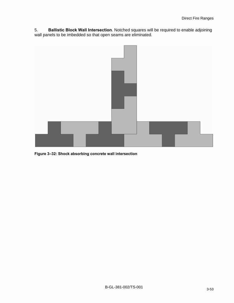
Direct Fire Ranges
5. Ballistic Block Wall Intersection. Notched squares will be required to enable adjoining wall panels to be imbedded so that open seams are eliminated.
Figure 3–32: Shock absorbing concrete wall intersection
B-GL-381-002/TS-001 3-53

Range Construction and Maintenance
Figure 3–33: Preliminary elevation plan steel panel shoot-house
B-GL-381-002/TS-001 3-54

Direct Fire Ranges
Figure 3–34: Preliminary floor plan steel panel shoot-house
B-GL-381-002/TS-001 3-55
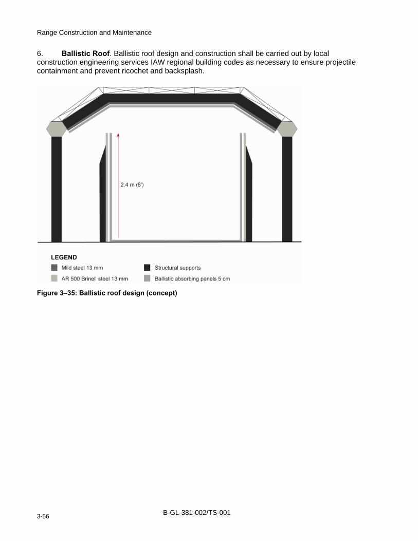
Range Construction and Maintenance
6. Ballistic Roof. Ballistic roof design and construction shall be carried out by local construction engineering services IAW regional building codes as necessary to ensure projectile containment and prevent ricochet and backsplash.
Figure 3–35: Ballistic roof design (concept)
B-GL-381-002/TS-001 3-56

Direct Fire Ranges
Figure 3–36: Preliminary floor plan shock absorbing concrete shoot-house
B-GL-381-002/TS-001 3-57

Range Construction and Maintenance
Figure 3–37: Steel panel wall configuration
B-GL-381-002/TS-001 3-58

Direct Fire Ranges
Figure 3–38: Sample environmental cover exterior
B-GL-381-002/TS-001 3-59

Range Construction and Maintenance
Figure 3–39: Sample environmental cover interior
B-GL-381-002/TS-001 3-60

Direct Fire Ranges
Figure 3–40: Shock absorbing concrete
B-GL-381-002/TS-001 3-61


Range Construction and Maintenance
ANNEX A TO CHAPTER 3 CONVENTIONAL RANGE INSPECTION CHECKLIST
1. Base/Station/Camp/Unit: _________________________
2. Range/Training Area (Name and Type): _____________
3. Date of Inspection: ______________________________
4. Inspected by: __________________________________
Serial Description of Item
Satis
fact
ory
Uns
atis
fact
ory
Uns
afe
Dem
olis
hed
a. Is a CHQ—or NDHQ—approved Weapons Range Authorization Form posted in a conspicuous place?
1
b. Is it current, and does it accurately describe the type of weapons for which the range is to be used and pertinent limitations?
2 Are there any indications that the range is being used incorrectly, or that live firing is being conducted using weapons for which the range is not designed (as described in serial 1)?
a. Are approved range orders, as applicable, posted in a conspicuous location on the range and protected from the elements?
b. Are they complete and up-to-date?
3
c. Are danger area traces and templates available for the applicable weapons or, conversely, are danger areas illustrated on a map or scaled sketch of the range? (Chapter 2 of B-GL-304-003/TS-0A1.)
a. Does new local construction, i.e. urban development, or change in the layout of the ranges (addition of new installations, new roads or tracks, etc) in any way affect the present range boundaries or use of the range?
b. In the event of changes occurring (as described in 4a above), can danger area traces or templates still be applied to the range configuration and still assure adequate safety margins? (See appropriate Annex to Chapter 2 B-GL-304-003/TS-0A1.)
c. Are arc markers on ranges clearly visible and correctly located?
4
d. Can present danger areas be reduced further (by adjustments to the arcs or relocation of the firing points) on field firing type ranges without decreasing the effectiveness of the range?
a. Is the present condition of the ground in the danger area (e.g. ice, frozen ground, excess undergrowth, and unearthed boulders) likely to lead to a greater incidence of ricochets?
5
b. Should temporary limitations be placed on firing until the condition has been remedied or other corrective
B-GL-381-002/TS-001 3A-1

Range Construction and Maintenance
Serial Description of Item
Satis
fact
ory
Uns
atis
fact
ory
Uns
afe
Dem
olis
hed
measures taken? 6 Are communication facilities in place, functioning and adequate, considering
the layout, type of range and its location for the following:
a. the butts; b. sentry posts at access points on the range
boundaries; and
c. the base HQ and the range? 7 Are range boundaries clearly indicated by notice boards, trespassing signs,
RED flags or lights at access points and prominent locations as required by Chapter 1 of B-GL-304-003/TS-0A1?
8 Are warning and control flags and lights available in the correct sizes and colours for the various ranges?
9 Are warning systems, flags and lights serviceable? 10 Does thick undergrowth or tall grass affect visibility of target areas or are
they likely to present a fire hazard when firing smoke or HE?
11 Are restricted impact areas shown on all range control maps and are they up to date?
12 Are danger area and ricochet templates appropriate and up-to-date for each training area or range?
13 Are controls in effect to prevent live or spent ammunition being removed from the range by unauthorized personnel?
14 Are range clearance operations conducted? How often? By whom? 15 What is the level of training of personnel and what training is given prior to
clearance operations?
16 Does Range Control or the supporting base have qualified personnel and staff for the destruction of duds and misfired ammunition?
17 Are blinds reported and recorded and, if so, when are they destroyed and by whom?
18 What are range scrap disposal procedures and are they in accordance with B-GL-304-003/TS-003?
19 Are containers available for spent casings and links? 20 If the range has a workshop area for weapon cleaning, target storage, etc, is
the entrance correctly signed, with sign DND 9905-21-855-4667 forbidding persons to take live ammunition inside?
ASSESSMENT OF OVERALL CONDITION ACTION REQUIRED
B-GL-381-002/TS-001 3A-2
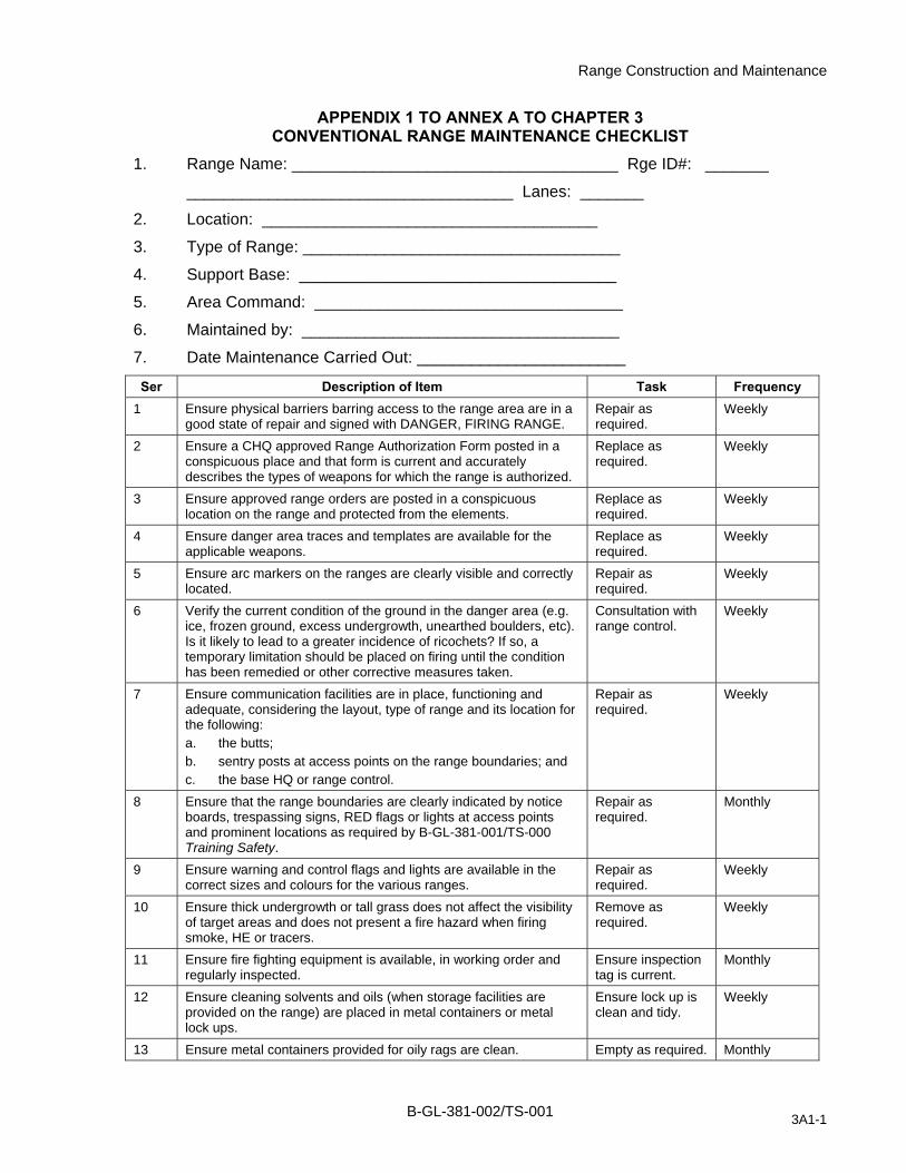
Range Construction and Maintenance
APPENDIX 1 TO ANNEX A TO CHAPTER 3 CONVENTIONAL RANGE MAINTENANCE CHECKLIST
1. Range Name: ____________________________________ Rge ID#: _______
____________________________________ Lanes: _______
2. Location: _____________________________________
3. Type of Range: ___________________________________
4. Support Base: ___________________________________
5. Area Command: __________________________________
6. Maintained by: ___________________________________
7. Date Maintenance Carried Out: _______________________
Ser Description of Item Task Frequency 1 Ensure physical barriers barring access to the range area are in a
good state of repair and signed with DANGER, FIRING RANGE. Repair as required.
Weekly
2 Ensure a CHQ approved Range Authorization Form posted in a conspicuous place and that form is current and accurately describes the types of weapons for which the range is authorized.
Replace as required.
Weekly
3 Ensure approved range orders are posted in a conspicuous location on the range and protected from the elements.
Replace as required.
Weekly
4 Ensure danger area traces and templates are available for the applicable weapons.
Replace as required.
Weekly
5 Ensure arc markers on the ranges are clearly visible and correctly located.
Repair as required.
Weekly
6 Verify the current condition of the ground in the danger area (e.g. ice, frozen ground, excess undergrowth, unearthed boulders, etc). Is it likely to lead to a greater incidence of ricochets? If so, a temporary limitation should be placed on firing until the condition has been remedied or other corrective measures taken.
Consultation with range control.
Weekly
7 Ensure communication facilities are in place, functioning and adequate, considering the layout, type of range and its location for the following: a. the butts; b. sentry posts at access points on the range boundaries; and c. the base HQ or range control.
Repair as required.
Weekly
8 Ensure that the range boundaries are clearly indicated by notice boards, trespassing signs, RED flags or lights at access points and prominent locations as required by B-GL-381-001/TS-000 Training Safety.
Repair as required.
Monthly
9 Ensure warning and control flags and lights are available in the correct sizes and colours for the various ranges.
Repair as required.
Weekly
10 Ensure thick undergrowth or tall grass does not affect the visibility of target areas and does not present a fire hazard when firing smoke, HE or tracers.
Remove as required.
Weekly
11 Ensure fire fighting equipment is available, in working order and regularly inspected.
Ensure inspection tag is current.
Monthly
12 Ensure cleaning solvents and oils (when storage facilities are provided on the range) are placed in metal containers or metal lock ups.
Ensure lock up is clean and tidy.
Weekly
13 Ensure metal containers provided for oily rags are clean. Empty as required. Monthly
B-GL-381-002/TS-001 3A1-1

Range Construction and Maintenance
Ser Description of Item Task Frequency 14 Ensure heating appliances (where applicable) are properly
maintained and operating instructions posted. Repair as required.
Weekly
15 Ensure target frames are serviceable. If they present a ricochet hazard, the exposed metal must be faced with the appropriate thickness of wood.
Repair as required.
Weekly
16 Ensure there is a suitable stop butt and that it is in good repair. Repair as required.
Monthly
17 Ensure bullet catchers are raked at least once a week if firing has taken place.
Maintain as required.
Weekly
18 Check for evidence of "tunnelling" in the stop butt. Repair as required.
Weekly
19 Ensure all firing points are in serviceable condition. Repair as required.
Weekly
20 Ensure personnel shelters (including shelter areas in the butts) weapon pits, firing trenches, etc, are in serviceable condition and adequate for the protection of the numbers of personnel for which designed.
Repair as required.
Monthly
21 Ensure lighting systems that are installed on the outdoor ranges are functioning.
Repair as required.
Weekly
22 Ensure mechanical target apparatus (if applicable) is serviceable and properly maintained.
Repair and grease as required.
Monthly
23 If the range has a workshop area for weapon cleaning, target storage, personnel shelters, etc, ensure the entrance is correctly signed, with sign DND 9905-21-855-4667 forbidding persons to take live ammunition inside.
Replace as required.
Monthly
24 Ensure target number boards are in a good state of repair. Repaint or replace as required.
Monthly
25 Ensure surface protection or ground cover is stable. (not more than 5% loss)
initiate construction or landscaping upgrades
repair annually
B-GL-381-002/TS-001 3A1-2

Range Construction and Maintenance
ANNEX B TO CHAPTER 3 GALLERY (INDOOR) RANGE MAINTENANCE CHECKLIST
1. Range Name: ___________________________________Rge ID#: _______
___________________________________Lanes: _______
2. Location: ___________________________________
3. Type of Range: _________________________________
4. Support Base: _________________________________
5. Area Command: ________________________________
6. Maintained by: _________________________________
7. Date Maintenance Carried Out: _____________________
Ser Description of Item Task Frequency 1 Ensure physical barriers, barring access to the indoor range area
are in a good state of repair and signed with DANGER, FIRING RANGE.
Repair as required. Weekly
2 Ensure that a CHQ approved range authorization form is posted in a conspicuous place and that it's current and accurately describes the type of weapons authorized.
Affix as required. Weekly
3 Ensure the following warning signs are posted: "HEARING PROTECTION REQUIRED" "NO EATING/DRINKING IN THIS AREA" "POTENTIAL LEAD CONTAMINATION HAZARD" "NO SMOKING"
Affix as required. Weekly
4 Ensure all electrical switches, light bulbs, are in good working order. Replace as required.
Weekly
5 Ensure firing stands for pistols/revolvers if applicable are in good condition.
Repair as required. Weekly
6 Ensure bullet catchers are raked and sifted (replace sand/sawdust (50/50) after 30,000 rds have been fired).
Rake as required. Monthly
7 Ensure target frames are serviceable. Replace as required.
Monthly
8 Ensure Linatex curtain is serviceable and in good condition (if applicable).
Replace as required.
Monthly
9 Ensure that containers for spent casings are available and that the spent casings are periodically disposed of.
Action as required. Monthly
10 Ensure fire fighting equipment available is in good working order, and regularly inspected.
Ensure inspection tag is current.
Monthly
11 Are cleaning solvents and oils, (when storage facilities are provided on the range) placed in metal containers, or metal lock-ups?
Ensure lock-up is clean and tidy.
Weekly
12 Ensure metal containers provided for oily rags are clean. Empty as required. Monthly 13 Ensure the heating appliances (where applicable) are properly
maintained and operating instructions posted. Repair as required. Weekly
14 Ensure the floors, walls and firing platforms are clean and the lane and firing point marking lines are visible.
Clean and paint as required.
Monthly
15 Ensure all obstructions forward of the firing points on the side walls, ceilings and floors, which are liable to cause ricochets/back-splash are protected.
Repair as required. Monthly
B-GL-381-002/TS-001 3B-1

Range Construction and Maintenance
16 Ensure all lights, electrical fixtures and conductors located forward of the firing point are protected.
Repair as required. Monthly
17 Ensure the target frames are serviceable. If they present a ricochet hazard, the exposed metal must be faced with appropriate thickness of wood.
Repair as required. Weekly
18 Ensure that the area of the stop butts is painted flat black. Paint as required. Monthly 19 Ensure ventilation exhaust fans are working. Repair as required. Weekly 20 Ensure any extra doors into the range area can be bolted from the
inside. Repair as required. Weekly
21 Ensure that the approved range orders are posted in a conspicuous location on the range.
Replace as required.
Weekly
22 If the range has a workshop area for cleaning weapons, target storage, etc, is the entrance correctly signed forbidding persons to take live ammunition inside?
Replace sign as required.
Weekly
23 Ensure right of use form (if applicable) is displayed and is current. Replace as required.
Weekly
24 Ensure personal respirators and disposable coveralls are used during range cleaning.
Replace protective equipment as required.
Weekly
25 Ensure that the lead exposure table, OCCUPATIONAL USE PERMISSIBLE EXPOSURE LIMITS IN INDOOR FIRING RANGES (NO RESPIRATORY PROTECTED) from B-GL-381-001/TS-000 is posted in a conspicuous location on the range.
Replace as required.
Weekly
26 Ensure that the PMed Tech date of inspection for Airborne Lead Concentration is not out of date.
Contact the Pre Med Tech as required.
Monthly
B-GL-381-002/TS-001 3B-2

Range Construction and Maintenance
ANNEX C TO CHAPTER 3 LIVE-FIRE SHOOT HOUSE INSPECTION CHECKLIST
1. Facility Name: ________________________________
2. Facility ID No: ________________________________
3. Location: ____________________________________
4. Support Base: ________________________________
5. Area Command: ______________________________
6. Inspected By: ________________________________
7. Date of Inspection: ____________________________
Serial Description of Item
Satis
fact
ory
Uns
atis
fact
ory
Uns
afe
Dem
olis
hed
GENERAL INFORMATION 1 Does Range Control Standing Orders reflect all requirements as
posted in applicable safety and maintenance manuals?
2a 2b
Does a proper template diagram exist for the facility? If not, does a waiver exist and is it documented in the CFRIS pgm?
3a
3b
On initial inspection does the ricochet template interfere with any public access road networks? Are other activities (Mil/Civ) performed during a live fire shooting practice within the vicinity of the structure or within a ricochet template. How many buildings/rooms make up this site? What size is the area encompassing the site? Is there an AAR building or structure in the vicinity?
4a
4b
Does Range Control hold a certificate from an engineering authority (since the last annual inspection) stating that all structures within the site have been inspected and are structurally sound?
X-ray/Scan of the AR500 walls and surfaces for structural integrity.
5a
5b
Is the structure(s) on a hard or soft prepared site? Are any environmental test wells in place to monitor possible leeching?
SITE EXTERIOR
6a
6b
Is the site secured with fencing and locked when not in use. In the case of non-existent fencing, are all doors at the site locked? Are warning signs posted, keeping unauthorized personnel out of the area when the site is in use?
7 Is the site clean and in good order? Are there signs of un-repaired training activities, e.g.: holes, refuse, or salvage?
B-GL-381-002/TS-001 3C-1

Range Construction and Maintenance
Serial Description of Item
Satis
fact
ory
Uns
atis
fact
ory
Uns
afe
Dem
olis
hed
8 Is a copy of the CFRIS licence posted in a conspicuous location at the site and protected from the elements?
9 Is the license current and does it accurately describes the type of training for which the site is to be used and any restrictions listed?
10 Are there indications that the site is being used incorrectly? 11 Any undue damage has occurred due to misuse of the structures?
e.g.: bullet strikes to the outer walls.
12 Does the structure appear to be solid? 13 Are there signs of rust in any of the target bullet stops of the structure
or bullet containment systems?
14 Are the bolts securing the main structure in place and tightly secured?
15 Are all doors and windows properly hinged and appear to be in good working condition?
16 Are there any signs of cracks, dimpling or faults on the outer shell of the structure?
17 Are all electronic devices installed and serviceable? 18 Is a tunnel system in place? Are access ports free and clear of
debris?
19 Are all sidewalks and prepared roadways in good condition without heaving/large cracks?
BUILDING/ROOM INTERIORS 20 Are there any signs of misuse of the buildings? 21 Is the interior clean and free of former training debris? 22 Are safety rails on stairwells secure and stable? 23 Are any surfaces susceptible to ricochets within the designated
engagement height/area?
24 Is the building interior free of animal nests and feces? 25a
25b
Is all training aids (bullet traps) within the structure or storage areas in good condition and providing a purpose? Are all rubber panels secured in place and in good condition?
UPPER LEVEL 26 Is there a ladder or stairwell provided to access upper walkway
(catwalk)?
27 Are railings and anchors secure in place? 28 Is a serviceable warning system in place for the OIC Prac?
B-GL-381-002/TS-001 3C-2

Annex C
Serial Description of Item
Satis
fact
ory
Uns
atis
fact
ory
Uns
afe
Dem
olis
hed
29 Does the upper structure provide a safe vantage point for the OIC at all entrances to the facility? Is the catwalk structured in such a way as to allow the OIC Prac to remain behind active shooters throughout the range practice?
ASSESSMENT OF OVERALL CONDITION: ACTION REQUIRED
NOTES This checklist may vary on the complexity of the Live Fire Shoot House
1. This inspection checklist is to be completed and filed by the inspecting officer at regular intervals in accordance with command directives. 2. The checklist may be used as the basis of a report or returned to Command Headquarters when so required. 3. When, in the opinion of an inspector, a live shoot house site does NOT meet the required safety standard, the CFRIS license will be suspended and all shooting activities will cease. 4. A report will be submitted, through the local operations staff and command channels, to DAT. The local construction engineer section will take corrective action prior to the reinstatement of the license.
B-GL-381-002/TS-001 3C-3


Range Construction and Maintenance
CHAPTER 4 INDIRECT FIRE RANGES
SECTION 1 INTRODUCTION
401. GENERAL
1. Indirect fire ranges will normally be positioned within an area that represents a natural operational environment and should require little preparation prior to use.
2. Several basic requirements must be met when locating and preparing an indirect fire range:
a. The training area and impact areas intended for use as an indirect fire range must be sufficiently large to permit the tactical movement and mobility of the training unit(s) and accommodate the specific danger areas for each weapon system.
b. Ranges that are limited in size and developed especially for mortars, must position the target or impact area so that round impacts are always visible from the firing point or the control tower.
c. One or more locations for observers and fire controllers shall be provided. These must be sufficiently elevated to afford a clear view of the impact area. They must be splinter and blast-proof for all intended munitions to be fired on the range.
d. Artillery ranges may also be used for mortars that have smaller danger areas.
3. Impact areas that are transacted by roads or trails shall be fitted with barriers and may require sentry posts to keep unauthorized personnel from entering the danger area.
4. The location of the impact area must not present a fire hazard to other base infrastructure, training areas or areas bordering the RTA.
5. All danger area boundaries must be clearly indicated as directed within Chapter 1 of B-GL-381-001/TS-000 Training Safety. The various signs to be posted are described in Chapter 1 of this volume.
6. The following infrastructure shall be provided on a conventional indirect fire range employing fixed gun positions located outside of the danger area and away from the firing points:
a. a troop shelter with heating and lighting;
b. sanitation facilities; and
c. a dry area for projectiles not used on the firing points (ammo point).
B-GL-381-002/TS-001 4-1

Range Construction and Maintenance
SECTION 2 60 MM MORTAR
402. GENERAL
1. The range should be at least 1500 m square.
2. Arc markers must be set up about 300 m in front of the firing positions. See Chapter 1.
403. DANGER AREA
1. The danger area for the 60 mm mortar is indicated in B-GL-381-001/TS-000 Training Safety Chapter 5, Annexes Y and Z. The 60 mm danger area template within CARSM shall be used to template this range.
2. The safety area extends 300 m behind the firing positions. Allowance must be made for this fact in the selection of rest areas and other sites specified in paragraph 7 of the introduction to this chapter.
404. FIRING POINT
1. When establishing a conventional range to fire the 60 mm mortars, sufficient space must be available at the firing line to permit positions to be in line at intervals of no less than 20 m. A maximum of four mortars may be in any one position with the firing line extending not more than 150 m.
2. In a conventional range setting, the 60 mm mortar must be fired from behind a splinter-proof cover. This cover shall be constructed as a low wall of packed earth 1 m in thickness and 80 cm high or double sandbagged to the front of a concrete block wall at least 80 cm high IAW B-GL-381-001/TS 000 Training Safety Annex Z. The wall shall extend at right angles to the center of the danger area template and be of sufficient length to provide adequate cover for the crew from their own weapon and those of each flanking weapon given all potential angles of impacts occurring at the minimum safe distance. This may be accomplished more effectively by angling each end of the wall at 30o or by creating a curved earthen wall.
3. The danger area of a 60 mm mortar extends to the rear of the base plate firing position equal to the minimum safe distance of the munitions in use and may extend to max of 300 m. Conventional 60 mm mortar ranges shall be designed to ensure that personnel who are not actively engaged in the firing of the 60 mm mortars are safety beyond the danger area and all buildings or other infrastructure are outside as well. As a minimum, personnel may be protected from accidental detonations by a low-wall constructed to the same standards as the wall in front of the firing position or be protected in a blast-proof bunker.
B-GL-381-002/TS-001 4-2

Indirect Fire Ranges
SECTION 3 81 MM MORTAR
405. GENERAL
1. The preceding guidance concerning to ground and firing points required for the 60 mm mortar also apply to the 81 mm mortar.
2. One or more observation posts (OP) may be necessary. The observers must be able to order a correction of fire from their position.
406. DANGER AREA
1. The danger area template for the 81 mm mortal will vary considerably according to the type of ammunition and the number of charges used. B-GL-381-001/TS-000 Training Safety lists these templates. When locating and constructing a 81 mm mortar range, the danger area templates that are within CARSM shall be used
SECTION 4 14.5 MM ARTILLERY AND 25 MM MORTAR TRAINER RANGES
407. GENERAL
1. The general requirements for an artillery or mortar trainer range are similar to those designed for operational ammunition. Overhead firing is permitted only if the OP is covered with 50 cm of earth or is adequately protected in some other way.
2. A flagpole must be erected in the most advantageous position possible in the range area so that a 2 x 2 m flag can be hoisted when the range is in operation.
3. All range boundaries must be marked as indicated in Chapter 1 of B-GL-381-001/TS-000 Training Safety and Chapter 1 of this volume.
408. CONSTRUCTION
1. When selecting a location for artillery or mortar trainers, the site shall be no less than 1,000 m square. The site shall be designed according to a scale of 1:10 (e.g. obstacles, variations in level, surface irregularities and buildings).
2. Once the site has been prepared, a map of the area shall be produced to a scale of 1:50,000 as follows:
a. establish reference points on the ground;
b. establish coordinates for the map;
c. plot the reference points on a sheet of grid paper to a scale of 1:50 000; and
d. fill in the details, including contour lines.
3. If the range is to be used on a repeated basis, then an appropriate store facilities and a troop shelter should be constructed near the firing points.
4. OPs shall be constructed to provide forward fire controllers an unobstructed view of the impact area. Normal radio communications shall be backed up with a land line between the OP and firing point.
B-GL-381-002/TS-001 4-3

Range Construction and Maintenance
5. One or more OPs may be located around the perimeter of the range or within the range boundaries. All OP locations shall be known in relation to the grid for the range and be marked clearly on the scale map.
409. FIRING POSITIONS
1. Firing positions may be selected for firing into the impact area from any direction, provided the location selected is on the same grid as is the range.
2. The location of the firing positions should provide the Gun Position Officer (GPO) with a good view of the range to ensure no one enters the range.
410. DANGER AREA
1. The danger area for the 14.5 mm shell is indicated in B-GL-381-001/TS-000 Training Safety. The danger area template within CARSM shall be used in the design of this range.
SECTION 5 105 MM AND 155 MM ARTILLERY RANGES
411. GENERAL
1. The site must be sufficiently large to include three regimental deployment areas, i.e. three areas of about 1 km square with access between them.
2. A suitable location 1500 m in front of the deployment area is required for setting up three OPs.
3. The impact area shall be approximately 3100 m long by 1600 m wide.
4. The site should be sufficiently large for targets to be engaged at the mean firing range of the weapon with the longest range that can be used.
412. DANGER AREA
1. Application of a danger area template for an artillery weapon will depend on a variety of factors including hardness of the ground, the number of charges used, the type of ammunition and various environmental factors.
2. B-GL-381-001/TS-000 Training Safety describes the danger area templates for the 105 mm and 155 mm howitzers on hard and soft ground. When designing a range for the 105 mm and 155 mm projectiles, the appropriate template shall be obtained in CARSM.
413. FIRING POSITIONS
1. Firing positions should be located to best represent the natural terrain encountered during operations with gun positions no less than 35 m apart. Dry level ground with no overhead obstacles and clear exit and enter routes is recommended.
B-GL-381-002/TS-001 4-4

Range Construction and Maintenance
CHAPTER 5 MISCELLANEOUS RANGES
SECTION 1 DEMOLITION RANGE
501. TYPES
1. The requirement for any particular type of demolition range will be determined in meeting the training capability or the explosive destruction tasks of the user units. Properly sited and designed demolition ranges can limit the propagation of noise and blast waves and mitigate the spread of demolitions scrape and energetic residue. The viability of trying to mitigate or remediate explosive residue will be determined by the type of soil or rock strata in the local area and so consultation with an Environmental Officer is advised. Figure 5–1 illustrates a typical demolition range layout.
2. Conventional demolition ranges are designed and constructed to maximize the safety and efficiency of formal demolitions classification training. Conventional demolition ranges incorporate all necessary danger area templates, initiation and firing points and permanent range structures as are needed for preparation of explosive materials, provision of range stores and troop shelter.
3. Field firing ranges are designed to accommodate tactical field training employing a variety of weapons and explosives. The field firing range may include the use of a manoeuvre box for the coordination of danger area templates according to the tactical scenario. Demolition tasks will be conducted within a tactical scenario under realistic operational conditions. Refer to B-GL-381-001/TS-000 Chapter 8.
4. Munitions disposal/destruction areas are designed to be used by CF Ammunition Depots and CF Bases for the destruction of surplus, obsolete and expired munitions. These may be co-located with conventional demolition ranges. Demolition destruction areas shall be licensed in accordance with C-09-153-001/TS-000 Explosive Safety Manual, Volume 1. Demolition destruction areas that are designated under control of the CF Ammunition Depots do not fall under the jurisdiction of the Chief of the Land Staff (CLS). See Figure 5–2.
502. SITE
1. The site chosen should have the following features and facilities:
a. a danger area radius of at least 1000 m;
b. rock free soil;
c. clear of surface or underground water source;
d. a nearby dead-end road;
e. good drainage;
f. minimum brush and trees to reduce the risk of fire;
g. bunker;
h. troop shelter;
i. ammunition points;
j. dry preparation shelter for fuse assembly; and
B-GL-381-002/TS-001 5-1

Range Construction and Maintenance
k. steel cutting area with earthen berm or splinter-proof wall.
2. There should be no obstacles within the danger area radius, such as:
a. a road or railroad with traffic;
b. power or gas lines above or under the ground;
c. buildings, tunnels or pipes that could be damaged;
d. rocks that could be propelled by an explosion; or
e. an air corridor or flight path.
3. Impact areas shall be planned to coincide with pre-existing impact areas.
4. As with the other types of ranges, the flags, signs and barriers must be in place when the range is in operation.
503. RANGE FEATURES AND FACILITIES
1. B-OW-320-009/FP-002 and B-GL-381-001/TS-000 Training Safety provide the danger area radius for each demolition.
2. Earthen Berm. Conventional demolition ranges configured with multiple firing points shall be constructed with earthen berms that separate individual firing points and provide protection for any building or structure that rests within the danger area. Berms shall run parallel to one another or at a right angle to any adjacent structure and be constructed using a rise over run ratio of no less that 3:2 m to a maximum height and minimum separation that meets the maximum combined net explosive weight requirements as licensed for that facility. Berms must not impede the movement of training or safety staff.
3. Bunker. Bunkers shall be located at the minimum safe distance from the firing point according to that specified for the combined net explosive weight licensed for that facility. Bunkers shall provide protection to troops from explosive overpressure, fragments and splinters. B-GL-361-012/FP-000 Accommodations, Installations and Engineering Services provides guidance on protection required with respect to such buildings however detailed specification have not yet been disseminated. The minimum safe distance of a bunker shall be no less than 90 m from the demolition point.
4. Dry Preparation Shelter. A blast-proof shelter shall be constructed on all conventional demolition ranges for the purpose of initiation set preparation. This area shall not be used in combination with or for the storage of explosive charges.
5. Troop Shelter. A troop shelter may be constructed out of the danger area to provide protection from the elements and a dry training area for waiting serials. An administration area may include parking lots, latrines etc.
6. Warning System. A warning system shall be available on all conventional demolition ranges. This system may consist of hand-held devices or may be attached to poles positioned at each quadrant of the conventional demolition range.
B-GL-381-002/TS-001 5-2

Miscellaneous Ranges
SECTION 2 FRAGMENTATION GRENADE RANGE
504. GENERAL
1. Conventional grenade ranges are specifically intended for classification training and qualification on the use of operational fragmentation grenades. These facilities are designed to permit preparation and use of fragmentation grenades under maximum safety conditions. The design features that are intended to ensure safety shall be maintained in satisfactory condition at all times
505. DANGER AREA
1. Conventional fragmentation grenade ranges shall have a clearly marked danger area in a 300 m radius around the detonation area IAW B-GL-381-001/TS-000 Training Safety.
506. FENCING
1. Where positive access control cannot be assured using sentries or other means, then the danger area shall be demarcated by means of a fence. The fence shall meet the construction requirements established in C-98-002-003/MS-003 Description, Installation and Maintenance of Fences. Danger warnings and flags should be put up in suitable places to indicate that the range is in operation.
507. THROWING BAY
1. Throwing bays shall be constructed of brick or concrete as shown in Figure 5–3. The throwing bay must be large enough to allow freedom of movement for the thrower and ARSO wearing full personal protective ensemble. The throwing bay shall be enclosed by walls 1.35 m in height and faced with 7.5 cm of pressure treated hardwood. The top surface of the throwing bay wall forward to the target area shall be flush with a slight incline at the interior edge to ensure the roll-out of any grenade into the target area that should land on top of the throwing bay wall. Entrance to each throwing bay shall be from a rear gallery that runs parallel to the throwing wall and which acts to isolate the throwing bays from the administration area and other throwing bays. Throwing bays shall be linked by a walled gallery to an adjacent safety bay. The throwing bay shall be fitted with a blast and fragmentation proof view port. Base Construction Engineering (BCE) is responsible for all construction standards.
508. CONTROL TOWER
1. A control tower shall be constructed on all conventional fragmentation grenade ranges. The control tower will provide a protected enclosure for the OIC Practice/RSO above and centered between the throwing bays. The control tower shall be constructed of brick or concrete with all exposed surfaces covered with a minimum of 7.5 cm of pressure treated wood. The OIC shall have an unobstructed view of the entire danger area through blast and fragmentation proof view ports. Access to the control tower shall be through a rear stairway constructed of wood or metal construction materials, with all exposed surfaces covered as above.
509. ASSEMBLY SHELTER
1. An assembly shelter is required to hold and protect personnel waiting their turn to throw grenades. The assembly shelter shall be constructed to the same standard as the throwing bays and control tower and all exposed surfaces that pose a ricochet hazard shall be faced with 7.5 cm of pressure treated hardwood. Figure 5–4 illustrates the design relationships between the
B-GL-381-002/TS-001 5-3

Range Construction and Maintenance
assembly shelter, the safety/preparation bay and the throwing bay in addition to the control tower. Two designs are possible IAW Figure 5–4.
510. VIEW PORTS
1. The control tower, throwing bays and assembly shelter shall be fitted with blast and fragmentation proof view ports to allow the OIC/RSO, ARSOs, throwers and spectators to see the detonation and effects of the fragmentation grenades.
2. View port specifications are as follows:
a. Each port shall be constructed of two layers of glazing consisting of an outer sacrifice layer (facing the detonation area) and an inner main protective layer (facing the safe area). The outer layer shall sustain damage from fragmentation while protecting the inner layer and personnel. The sacrifice and protective layers shall be separated by a 75 mm (3 in) airspace constructed as follows:
(1) protective layer shall be 31.75 mm (1 ¼ in) thick Lexgard RS 1250 Laminate; and
(2) sacrifice layer shall be two back/back Lexan 9034 sheets each of minimum thickness 12.7 mm (1/2 in).
b. This method of construction is suitable for current issue fragmentation grenades. Grenade range licenses shall not exceed the explosive charge beyond that of the C13 Grenade, Hand, Fragmentation.
511. MAINTENANCE
1. View Ports. The sacrifice layer shall be replaced at the first instance that the glazing is assessed to have deteriorated to a point just prior to the protective layer being exposed to blast and fragmentation. At no time should the protective layer be directly exposed to blast or fragmentation. The protective layer shall be replaced immediately upon detection of damage or deterioration (e.g. pitting or cracking). Follow supplier’s recommendations for regular maintenance/ replacement schedule.
2. Doors, Hinges and Gates. All doors, hinges and gates shall remain fully functional, fastened securely, painted and shall not pose a snagging hazard (e.g. protruding screws, nails, splinters).
3. Facing. All front walls, control tower, stairs and the inside of the throwing bays shall be covered by 7.5 cm thick facing of pressure treated hardwood to absorb fragmentation and eliminate ricochets into the throwing bays or observation areas.
4. Impact Area. At the completion of each firing exercise, all depressions in the impact areas shall be filled in with sand or soil available outside the impact area. No digging in the impact area is allowed.
5. Housekeeping. The site shall remain free of litter, target parts, grenade scrap or any foreign materials not directly related to the range practice. Grass and weeds shall not be allowed to grow in the impact area and all other grounds shall be cut to a height of 10 cm or less.
6. Snow and Ice Removal. When conducting grenade practices in the winter months and prior to any grenade practice, snow removal shall be undertaken to clear the impact area. Snow removal equipment must provide adequate protection against blast and fragmentation to protect the operator.
B-GL-381-002/TS-001 5-4

Miscellaneous Ranges
512. COMMUNICATIONS
1. The control tower should be fitted with a loud speaker system where communication with the throwing bays is impeded by the protective view ports and enclosed concrete structure. Communications with Range Control must also be assured using traditional fixed land line or radio equipment. The OIC/RSO shall remain in continuous contact with Range Control and the various shelter and bays on the grenade range.
513. TARGETS
1. Targets for fragmentation practices shall consist of Figure 11 on a support post supported by a base. No ricochet causing materials shall be placed in the danger area. No objects that may trap or otherwise obscure or hide a misfired fragmentation grenade shall be placed in the target area. Range practices shall be conducted IAW B-GL-381-001/TS-000 Training Safety and applicable Range Standing Orders.
514. POSTING BUNKER
1. Posting bunkers are designed to permit the placing or dropping of fragmentation grenades into a blast and fragment-proof structure so that the grenadier is protected from the explosive effects of the grenade.
2. Site selection must ensure that the bunker is isolated from the majority of troops manoeuvring in the surrounding area. While tactical reality is important, safety is paramount.
3. Inspection and maintenance shall be performed after three grenades are detonated in Type A trenches or after one detonation in a Type B bunker. Figures 5–5 to 5–8 illustrate various options for posting bunker design.
SECTION 3 M 203 GRENADE LAUNCHER RANGE
515. GENERAL
1. The C-149 High Explosive and M433 HEDP ammunition may only be fired into a Type 1 dangerous area otherwise designated as a closed impact area. The small size of the M 203 projectile prevents easy location should a misfire occur therefore the UXO hazard risk is high. Firing of the high explosive projectile is not to take place on a standard grenade range.
516. SITE
1. Points to consider when choosing a location to construct a M 203 range: a. the area must be sufficiently large to accept the M 203 danger area template and
where possible, avoid roads, trails and other infrastructure where workers may be required to cross the ground (e.g. power/communications lines);
b. level or slightly undulating ground should be selected to permit grenadiers to develop their skills in target identification, round placement and judging of distances;
c. the impact area shall be firm and free of natural features that can trap and hide projectiles. Soft surfaces and areas where it would be difficult to locate duds should be avoided; and
d. the impact area should be relatively free of vegetation and away from environmentally sensitive and protected areas.
B-GL-381-002/TS-001 5-5

Range Construction and Maintenance
2. All conventional grenade launcher ranges shall be designated as a Type 1 dangerous area. The dedicated high impact area will be fenced off and posted with signs to warn and keep out unauthorized personnel. See annex AG, page 2AG–1 of B-GL-381-001/TS-000 Training Safety for the danger area templates for the various categories of ammunition.
517. RANGE LAYOUT
1. The firing point shall consist of a series of fire trenches and fire walls. Each position must be large enough for two soldiers. Each position shall be no less than 6m apart from edge to edge. Figure 5–9 illustrates the dimensions of a fire trench and fire wall.
2. Conventional grenade launcher ranges shall be designed to provide a protective barrier for the OIC/RSO.
3. The safety barrier shall be constructed in a manner that will allow the OIC/RSO to see and communicate with the firers and observe all of the impact area.
4. Alternately, a control tower may be constructed in place of the OIC/RSO safety barrier. The control tower shall be constructed to the same specifications as those for a conventional fragmentation grenade range. The control tower must enable the OIC/RSO to see and communicate with all the firers and observe all of the impact area.
5. The ready wall is used to protect waiting serials for their turn to embark onto the firing point.
6. All front walls shall be covered by 7.5 cm thick facing of pressure treated hardwood to reduce ricochets into the firing points or observation areas.
7. Appropriate high explosive no-fire lines will be established for the HEDP M433 and the HE/SD 149 in the target area. See Figure 5–10.
SECTION 4 MARCOM WEAPON RANGES
518. AUTHORITY
1. While this publication provides guidance and policy on the construction and maintenance of land based ranges and facilities common to the three Environmental Commands, responsibility for the design, construction and maintenance of MARCOM weapon ranges is vested in the Chief of Maritime Staff (CMS).
2. When a RTA custodian (Base, Wing Station or Camp Commander) is responsible for both maritime and land weapon ranges, then the MARCOM N3 shall be responsible for the design, construction and maintenance of MARCOM ranges to ensure that there is as little conflict as possible with the land based facilities in that installation. MARCOM/N3 and LFDTS/DAT retain staff responsibilities for their respective ranges.
519. REFERENCE BOOK
1. Orders and instructions governing MARCOM ranges and Range Standing Orders are contained in Maritime Command Orders (MARCORDS).
B-GL-381-002/TS-001 5-6

Miscellaneous Ranges
SECTION 5 AIR WEAPON RANGES
520. AUTHORITY
1. While this publication provides guidance and policy on the construction and maintenance of land based ranges and facilities common to the three Environmental Commands, responsibility for the design, construction and maintenance of air to air and air to ground weapon ranges is vested in the Chief of Air Staff.
2. When a RTA custodian (Base, Wing Station or Camp Commander) is responsible for both air and land weapon ranges, then the AIRCOM A3 shall be responsible for the design, construction and maintenance of air ranges to ensure that there is as little conflict as possible. 1 Canadian Air Division A3 and LFDTS DAT retain staff responsibilities for their respective ranges.
521. REFERENCE BOOK
1. C-07-010-011/TP-000 Canadian Forces Air Weapon Ranges, is the reference work on the construction of the various types of range, targets, danger areas, etc. This publication also identifies the names of all authorized air weapon ranges and provides information on the inspection of these ranges.
SECTION 6 ADATS AND GDF 005 35 MM ANTI-AIRCRAFT GUN
522. SITE
1. Point and area anti-air weaponry, including the ADATS and the GDF 35 mm anti-aircraft gun, do not require the construction of conventional range facilities to complete classification and continuation training. Therefore, the primary requirement for an anti-aircraft firing range is to assure a firm and clear firing surface, good all-round visibility and sufficient space for the particular danger area to be used. The danger areas for air-defence weapons are described in B-GL-381-001/TS-000 Training Safety.
2. All GDF 005 35 mm ranges intended for training with HEI, HEI-T, HEI-P or SAPHEI-T shall be designated Type 1 dangerous areas.
3. Ranges shall not be sited to intersect or straddle a commercial air corridor. A NOTAM shall be published for all ranges that are templated for air-defence weapon systems.
523. RANGE LAYOUT
1. Ranges should be designed to assure positive control of all UXO producing ammunition so that unnecessary contamination is avoided. Ranges should provide firing positions on elevated terrain to assure a clear line of sight for gunners, radar and lasers. Entrance and exit routes must remain clear of UXO if dismounted movement is a probability otherwise; travel shall be restricted to mounted movement as per Type 1 dangerous area restrictions.
524. ARCS 0F FIRE AND FLAGS
1. The arcs of fire are normally marked out by ribbons on the gun or by pegs opposite the gun. Sometimes outside arcs of fire are indicated by arc of fire markers as explained in Chapter 1. Range boundaries shall be marked IAW Chapter 1. All areas used shall be marked for laser safety as well.
B-GL-381-002/TS-001 5-7

Range Construction and Maintenance
SECTION 7 SKEET/TRAP RANGE
525. GENERAL
1. Recreational trap and skeet ranges provide a safe and environmentally sustainable venue for sport and competition shooting. Single (skeet or trap) or dual-purpose (skeet and trap) ranges are designed to simulate fast moving flying targets to practice shooters in the application of range, elevation and lead.
2. A range can be laid out for simultaneous skeet and trap shooting. If the range is designed for both types of shooting, it must be evaluated and designed accordingly.
526. SITE
1. Skeet and trap ranges shall be sited on firm level ground that is free of vegetation. Skeet and trap ranges shall not be sited near or adjacent to environmentally sensitive areas including waterways, wetlands or protected habitat.
527. SAFETY MEASURES
1. The danger area template for skeet and trap ranges shall be applied to cover all firing points and direction of fire and must be suitable to accommodate the most energetic projectiles to be discharged. B-GL-381-001/TS-000 Training Safety contains trap and skeet range danger area templates in a 300 m radius.
2. Reductions to published danger area templates must be requested by the applicable range custodian through DAT RTA to DAEMG who acts as the ballistic template authority for the Land Force.
3. Range boundaries shall be marked with posts or poles erected 40.25 m from each house. The distance is measured longitudinally from each house passing through the crossing point.
528. AMMUNITION
1. Skeet and trap ranges on DND facilities are prohibited from using lead shot IAW federal environmental policy. All facilities shall use approved non-toxic shot. Range licenses shall not be approved for facilities that use lead shot.
529. TARGET THROWERS
1. Skeet and trap ranges utilize mechanical trap machines or target throwers that launch brittle disks out and across the firing lane. Firing points are positioned behind the target throwers to enable shooters to engage and hit the targets in flight as they are launched on a variety of fixed flight lines within the range template.
2. Mechanical target throwers must be maintained in good operating condition to reliably throw targets within the target flight line. If a manual target thrower is used, the operator must be familiar with its operation and the safety zone boundaries.
3. In a skeet range, it is important to ensure consistency in terms of firing direction and height. To help verify the target flight line, a post or pole should be erected at the crossing point of targets thrown from the high and low houses. The post must be erected approximately 5.5 m in front of firing point No. 8.
B-GL-381-002/TS-001 5-8
Miscellaneous Ranges
530. TARGETS
1. Skeet and trap ranges on DND facilities are prohibited from using clay pigeons that contain polycyclic Aromatic Hydrocarbons (PAH) IAW federal environmental policy. All such facilities shall use approved non-toxic clay pigeons. Range licenses shall not be approved for facilities that continue to use PAH contaminated targets.
531. MAINTENANCE
1. Skeet and trap ranges will be cleaned of all visible pellets, ammunition casings and target fragments three times annually. Grounds shall be free of litter, grass cut and snow removed seasonally to assure freedom of movement.
2. All doors, hinges and gates shall remain fully functional, fastened securely, painted and shall not pose a snagging hazard (e.g. protruding screws, nails, splinters).
532. RANGE LAYOUT
1. The live zone of trap and skeet ranges includes the area where the firing points and the houses (or trap houses) are located. It also includes the area in front of the firing points to a depth equivalent to the length of the flight line of the targets thrown, i.e. approximately 65 m.
533. SKEET OR TRAP HOUSES
1. Skeet houses (or trap houses) are located on each side of the range. The high house is to the left and the low house to the right, approximately 38.8 m apart. Figures 5–11 and 5–12 illustrate a typical range layout. These structures contain the target thrower mechanisms and may contain targets.
2. Ranges with several adjacent skeet shooting ranges may use combination high-low houses.
3. House exteriors may be painted beige or off white to allow shooters to easily distinguish thrown targets.
4. The houses are designed to contain a manual or automatic-loading target thrower. The critical dimensions of the houses, i.e. height and width, are determined by the user or governing body of the sport. Normally, building specifications are available through the governing body of the sport, target manufacturers or ammunition manufacturers.
5. The dimensions of unmanned houses are to be determined by the user.
6. Houses containing manual target throwers require operators. Construction specifications for these types of houses are specified below and aim to protect thrower operators.
7. The cabin side and back walls (and door, if applicable) must:
a. withstand shot impact in the operator’s work area, to a height of 2.5 m from the floor;
b. if the house is to be of wood frame construction, then the outer surface must be faced with two layers of 5.08 cm boards fastened together to ensure overlap of joints; and
c. if the house is of concrete or concrete block construction, no other protection is necessary.
8. If operators are visible (in their normal working position) from firing points 1, 7 or 8, a steel plate shield must be fitted to the exterior of the house to protect the operator from stray
B-GL-381-002/TS-001 5-9

Range Construction and Maintenance
projectiles. The shield must be designed to ensure that operators (in their normal working positions) are not exposed to projectiles fired into the house from any firing point.
9. Other than the door and the opening from which the targets are thrown, there should be no openings or windows in the area of the house used by the operators.
10. In a prominent location in the house, a warning sign must be posted that states the following:
a. do not look out the shield when the range is in operation;
b. do not put your hand in the shield when the range is in operation; and
c. do not leave the protected area of the house unless you have been granted permission to do so by the RSO.
11. Houses with manual target throwers must be equipped with a YELLOW flag (approx. 30 cm x 45 cm) mounted on a short flagstaff. The house operators must use the flag to signal a cease-fire to the RSO and shooters in the event that a target thrower malfunctions or requires reloading.
SECTION 8 SKEET RANGE
534. RANGE CONFIGURATION
1. A skeet range is configured with two houses that flank the range, with a high house on the left flank and a low house on the right, from which targets are projected from a throwing mechanism. Each is located at opposite ends of the half moon set at a radius of 19.2 m. Seven firing points are positioned along the half moon with an eighth point located at the centre of the range, halfway between the high and low houses. See Figure 5–12.
535. FIRING POINTS
1. Skeet range firing points:
a. must be clearly identified;
b. must be level and provide shooters with good traction in inclement weather; and
c. gravel or concrete pads/walkways are recommended.
2. The recommended size of a firing point is 90 cm square, i.e. 90 cm x 90 cm.
3. Figure 5–12 illustrates a typical skeet range layout. The specific location of the firing points must comply with the requirements contained in the regulations governing the sport.
536. BARRIER FENCE FOR ADJACENT SKEET RANGES
1. When a range contains at least two adjacent skeet ranges, a fence must separate the ranges. The fence is required to protect shooters in adjacent ranges from targets and projectiles that may inadvertently stray into the adjacent range.
2. The barrier fence must meet or exceed the construction requirements set out in Figure 5–14. A minimum height of 3.07 m and minimum length of 12.2 m shall be maintained.
537. FIELD FIRING SKEET RANGE LAYOUT
1. These ranges are easy to build and operate. They include a manual or automatic target thrower as well as one or several firing points. See Figure 5–12 for range layout.
B-GL-381-002/TS-001 5-10

Miscellaneous Ranges
538. FIRING POINTS
1. Field firing skeet range firing points:
a. Must be clearly identified.
b. Must be situated crosswise in relation to the target thrower.
c. Must be level and provide a proper foundation for shooters in inclement weather; gravel or concrete pads/walkways are recommended.
d. The recommended size of firing points is 90 cm square.
SECTION 9 TRAP RANGES
1. A typical trap field layout includes a single trench located in front of a series of firing points placed in a triangular shape. See Figure 5–13.
539. TRENCH
1. This structure contains the target thrower(s) and target stocks. Trenches are designed to contain manual or automatic-loading target throwers. The floor area of a typical trench is approximately 2.4 m2. The trench may be surface built or partly below ground level. The governing body of the sport determines trench dimensions, i.e. height and width.
2. Trenches equipped with manual target throwers will be occupied by the operator. Construction requirements for these types of trenches are indicated below. Trench design shall ensure full protection for the operator.
3. Visible parts of the trench (roof, side and back walls) must be able to withstand shot impact and be constructed of no less than 10 cm thickness of poured concrete or other material that meets this requirement (i.e. filled concrete blocks). It is recommended that the roof be made of reinforced concrete or mild steel.
4. The sides or rear of the trench shall not be constructed with windows or openings.
5. A sign must be posted in a prominent location inside the working area in the trench warning the operators not to leave the trench unless permission to do so is granted by the RSO.
6. Trenches with manual target throwers must be equipped with a YELLOW flag (approx. 30 cm x 45 cm) mounted on a short flagstaff. The trench operator must use the flag to signal a cease-fire to the RSO and shooters in the event that a target thrower malfunctions or requires reloading.
540. FIRING POINTS
1. Trap field firing points shall:
a. Be clearly identified.
b. Be level and provide a proper foundation for shooters in inclement weather; gravel or concrete pads/walkways are recommended.
c. Use the 90 cm square recommended size firing points. See Figure 5–13 for a typical trap field layout.
d. Use the recommended size skeet range barrier fence. See Figure 5–14 for fence layout.
B-GL-381-002/TS-001 5-11


Range Construction and Maintenance
ANNEX A TO CHAPTER 5
Figure 5–1: Demolition range
B-GL-381-002/TS-001 5A-1

Range Construction and Maintenance
Figure 5–2: Destruction area layout
B-GL-381-002/TS-001 5A-2

Annex A
Figure 5–3: Grenade throwing bay
B-GL-381-002/TS-001 5A-3

Range Construction and Maintenance
Figure 5–4: Viewports
B-GL-381-002/TS-001 5A-4

Annex A
B-GL-381-002/TS-001 5A-5
Figure 5–5: Tactical Grenade Posting Type “A” Target Trench

Range Construction and Maintenance
Figure 5–6: Tactical Grenade Posting Type “A” Target Trench Alternative Materials
B-GL-381-002/TS-001 5A-6

Annex A
Figure 5–7: Tactical Grenade Posting Type “B” Target Bunker
B-GL-381-002/TS-001 5A-7

Range Construction and Maintenance
Figure 5–8: Tactical Grenade Posting Type “C” Target Window
B-GL-381-002/TS-001 5A-8

Annex A
Figure 5–9: Grenade launcher range firing point
B-GL-381-002/TS-001 5A-9

Range Construction and Maintenance
Figure 5–10: M 203 grenade launcher range layout
B-GL-381-002/TS-001 5A-10

Annex A
Figure 5–11: Sample trap house below ground and surface built
B-GL-381-002/TS-001 5A-11

Range Construction and Maintenance
Figure 5–12: Typical layout of a skeet range
Figure 5–13: Typical trap field layout
B-GL-381-002/TS-001 5A-12

Annex A
Figure 5–14: Skeet range barrier fence
B-GL-381-002/TS-001 5A-13


Range Construction and Maintenance
APPENDIX 1 TO ANNEX A TO CHAPTER 5 PERMANENT DEMOLITION RANGE MAINTENANCE CHECKLIST
1. Range Name: __________________________________ Rge ID#: _______
_____________________________________________ Lanes: _______
2. Location: ___________________________________
3. Type of Range: _________________________________
4. Support Base: _________________________________
5. Area Command: ________________________________
6. Maintained by: ___________________________________
7. Date Maintenance Carried Out: _______________________________
Ser Description of Item Task Frequency 1 Ensure physical barriers barring access to the range area are
in a good state of repair and are signed with "DANGER DEMOLITION RANGE".
Repair as required.
Weekly
2 Ensure that a CHQ approved range authorization form is posted in a conspicuous place and that it is current and accurately describes the types and quantities of explosives that are authorized.
Replace as required.
Weekly
3 Ensure warning signs to clearly prohibit and discourage unauthorized entry to the range area are in good condition and are serviceable
Replace as required.
Monthly
4 Ensure approved range orders are posted in a conspicuous location on the range and are protected from the elements.
Replace as required.
Weekly
5 Ensure communication facilities are in place (if applicable) taking into consideration the layout, type of range and its location for the following: a. the control point; b. sentry posts at access points on the range boundaries; and c. Range Control.
NOTE When using electrically initiated explosive devices (EIED), all safety precautions outlined in B-GL-381-001/TS-000 to be strictly adhered to when using radio transmitters.
Carry out complete radio functional check to ensure components are serviceable.
Weekly
6 Ensure all trees; dry grass and undergrowth within a radius of 60 m from the disposal point are removed.
Cut and clear as required.
Monthly
B-GL-381-002/TS-001 5A1-1

Range Construction and Maintenance
Ser Description of Item Task Frequency 7 Verify the present condition of the ground in the danger area,
i.e. ice, frozen ground, excess undergrowth, unearthed boulders, scrap metal, etc. Is it likely to lead to a greater incidence of ricochets? If so, a temporary limitation should be placed on demolition activities until the condition has been remedied or other corrective measures taken.
NOTE All munitions scrap is to be certified free of explosive by a qualified ammunition technician prior to transfer to the scrap yard.
Consult with Range Control. Remove any objects that could cause ricochets.
Weekly
8 Ensure fire fighting equipment is available, in working order and has been regularly inspected.
Ensure inspection tag is current.
Monthly
9 Ensure heating appliances in the troop shelter (if applicable) are properly maintained and operating instructions posted.
Repair as required.
Monthly `
10 Ensure detonator storage area (if applicable) is clean and in good repair.
Repair as required.
Monthly
11 Ensure observation bunker is clean, in good repair and the armoured glass has no cracks or fragmentation damage.
Repair as required.
Monthly
12 Ensure crater blowing area is clean and all craters are filled in.
Consult with user units. See *Note*
Weekly
13 Ensure steel cutting area is clean and tidy. Consult with user units. See *Note*
Weekly
14 Ensure concrete cutting area is clean and tidy. Consult with user units. See *Note*
Weekly
15 Ensure mine warfare area is clean and tidy.
Consult with user units. See *Note*
Weekly
16 Ensure material and scrap yard is emptied on a regular basis. Arrange with the CE Section to have the scrap material disposed of as required.
Monthly
17 Ensure warning flags/lights are the correct size and colour and are in good condition.
Replace as required.
Weekly
NOTE The user is responsible to fill all the craters, clean up all the debris and return the area to its original condition at the end of the practice session.
B-GL-381-002/TS-001 5A1-2

Range Construction and Maintenance
ANNEX B TO CHAPTER 5 GALLERY (INDOOR) RANGE MAINTENANCE CHECKLIST
1. Range Name: __________________________________ Rge ID#: _______
______________________________________________ Lanes: _______
2. Location: ___________________________________
3. Type of Range: _________________________________
4. Support Base: _________________________________
5. Area Command: ________________________________
6. Maintained by: _________________________________
7. Date Maintenance Carried Out: _____________________
Ser Description of Item Task Frequency 1 Ensure physical barriers, barring access to the indoor range
area are in a good state of repair and signed with DANGER, FIRING RANGE.
Repair as required.
Weekly
2 Ensure that a CHQ approved range authorization form is posted in a conspicuous place and that it’s current and accurately describes the type of weapons authorized.
Affix as required. Weekly
3 Ensure the following warning signs are posted: "HEARING PROTECTION REQUIRED" "NO EATING/DRINKING IN THIS AREA" "POTENTIAL LEAD CONTAMINATION HAZARD" "NO SMOKING"
Affix as required. Weekly
4 Ensure all electrical switches, light bulbs, are in good working order.
Replace as required.
Weekly
5 Ensure firing stands for pistols/revolvers if applicable are in good condition.
Repair as required.
Weekly
6 Ensure bullet catchers are raked and sifted (replace sand/sawdust (50/50) after 30,000 rds have been fired).
Rake as required. Monthly
7 Ensure target frames are serviceable. Replace as required.
Monthly
8 Ensure Linatex curtain is serviceable and in good condition (if applicable).
Replace as required.
Monthly
9 Ensure that containers for spent casings are available and that the spent casings are periodically disposed of.
Action as required.
Monthly
10 Ensure fire fighting equipment available is in good working order, and regularly inspected.
Ensure inspection tag is current.
Monthly
11 Are cleaning solvents and oils, (when storage facilities are provided on the range) placed in metal containers, or metal lock-ups?
Ensure lock-up is clean and tidy.
Weekly
12 Ensure metal containers provided for oily rags are clean. Empty as required.
Monthly
13 Ensure the heating appliances (where applicable) are properly maintained and operating instructions posted.
Repair as required.
Weekly
B-GL-381-002/TS-001 5B-1

Range Construction and Maintenance
14 Ensure the floors, walls and firing platforms are clean and the lane and firing point marking lines are visible.
Clean and paint as required.
Monthly
15 Ensure all obstructions forward of the firing points on the side walls, ceilings and floors, which are liable to cause ricochets/back-splash are protected.
Repair as required.
Monthly
16 Ensure all lights, electrical fixtures and conductors located forward of the firing point are protected.
Repair as required.
Monthly
17 Ensure the target frames are serviceable. If they present a ricochet hazard, the exposed metal must be faced with appropriate thickness of wood.
Repair as required.
Weekly
18 Ensure that the area of the stop butts is painted flat black. Paint as required. Monthly 19 Ensure ventilation exhaust fans are working. Repair as
required. Weekly
20 Ensure any extra doors into the range area can be bolted from the inside.
Repair as required.
Weekly
21 Ensure that the approved range orders are posted in a conspicuous location on the range.
Replace as required.
Weekly
22 If the range has a workshop area for cleaning weapons, target storage, etc, is the entrance correctly signed forbidding persons to take live ammunition inside?
Replace sign as required.
Weekly
23 Ensure right of use form (if applicable) is displayed and is current.
Replace as required.
Weekly
24 Ensure personal respirators and disposable coveralls are used during range cleaning.
Replace protective equipment as required.
Weekly
25 Ensure that the lead exposure table, OCCUPATIONAL USE PERMISSIBLE EXPOSURE LIMITS IN INDOOR FIRING RANGES (NO RESPIRATORY PROTECTED) from B-GL-381-001/TS-000 is posted in a conspicuous location on the range.
Replace as required.
Weekly
26 Ensure that the PMed Tech date of inspection for Airborne Lead Concentration is not out of date.
Contact the Pre Med Tech as required.
Monthly
B-GL-381-002/TS-001 5B-2

Range Construction and Maintenance
ANNEX C TO CHAPTER 5 LIVE-FIRE SHOOT HOUSE INSPECTION CHECKLIST
1. Facility Name: ____________________________________
2. Facility ID No: ____________________________________
3. Location: ________________________________________
4. Support Base: ____________________________________
5. Area Command: ___________________________________
6. Inspected By: _____________________________________
7. Date of Inspection: _________________________________
Serial Description of Item
Satis
fact
ory
Uns
atis
fact
ory
Uns
afe
Dem
olis
hed
GENERAL INFORMATION 1 Does Range Control Standing Orders reflect all requirements as
posted in applicable safety and maintenance manuals?
2a 2b
Does a proper template diagram exist for the facility If not, does a waiver exist and is it documented in the CFRIS pgm?
3a
3b
On initial inspection does the ricochet template interfere with any public access road networks? Are other activities (Mil/Civ) performed during a live fire shooting practice within the vicinity of the structure or within a ricochet template? How many buildings/rooms make up this site? What size is the area encompassing the site. Is there an AAR building or structure in the vicinity?
4a
4b
Does Range Control hold a certificate from an engineering authority (since the last annual inspection) stating that all structures within the site have been inspected and are structurally sound? X-ray/Scan of the AR500 walls and surfaces for structural integrity.
5a 5b
Is the structure(s) on a hard or soft prepared site? Are any environmental test wells in place to monitor possible leeching?
SITE EXTERIOR
6a
6b
Is the site secured with fencing and locked when not in use? In the case of non-existent fencing, are all doors at the site locked? Are warning signs posted, keeping unauthorized personnel out of the area when the site is in use?
7 Is the site clean and in good order? Are there signs of un-repaired training activities, e.g. holes, refuse, or salvage?
8 Is a copy of the CFRIS licence posted in a conspicuous location at the site and protected from the elements?
B-GL-381-002/TS-001 5C-1

Range Construction and Maintenance
Serial Description of Item
Satis
fact
ory
Uns
atis
fact
ory
Uns
afe
Dem
olis
hed
9 Is the license current and does it accurately describes the type of training for which the site is to be used and any restrictions listed?
10 Are there indications that the site is being used incorrectly? 11 Any undue damage has occurred due to misuse of the
structures?.e.g.: bullet strikes to the outer walls.
12 Does the structure appear to be solid? 13 Are there signs of rust in any of the target bullet stops of the structure
or bullet containment systems?
14 Are the bolts securing the main structure in place and tightly secured?
15 Are all doors and windows properly hinged and appear to be in good working condition?
16 Are there any signs of cracks, dimpling or faults on the outer shell of the structure?
17 Are all electronic devices installed and serviceable? 18 Is a tunnel system in place? Are access ports free and clear of
debris?
19 Are all sidewalks and prepared roadways in good condition without heaving/large cracks?
BUILDING/ROOM INTERIORS 20 Are there any signs of misuse of the buildings? 21 Is the interior clean and free of former training debris? 22 Are safety rails on stairwells secure and stable? 23 Are any surfaces susceptible to ricochets within the designated
engagement height/area?
24 Is the building interior free of animal nests and feces? 25a
25b
Is all training aids (bullet traps) within the structure or storage areas in good condition and providing a purpose? Are all rubber panels secured in place and in good condition?
UPPER LEVEL 26 Is there a ladder or stairwell provided to access upper walkway
(catwalk)?
27 Are railings and anchors secure in place? 28 Is a serviceable warning system in place for the OIC Prac? 29 Does the upper structure provide a safe vantage point for the OIC at
all entrances to the facility? Is the catwalk structured in such a way as to allow the OIC Prac to remain behind active shooters throughout the range practice?
B-GL-381-002/TS-001 5C-2

Annex C
Serial Description of Item
Satis
fact
ory
Uns
atis
fact
ory
Uns
afe
Dem
olis
hed
ASSESSMENT OF OVERALL CONDITION: ACTION REQUIRED
NOTES This checklist may vary on the complexity of the Live Fire Shoot House
1. This inspection checklist is to be completed and filed by the inspecting officer at regular intervals in accordance with command directives. 2. The checklist may be used as the basis of a report or returned to Command Headquarters when so required. 3. When, in the opinion of an inspector, a live shoot house site does NOT meet the required safety standard, the CFRIS license will be suspended and all shooting activities will cease. 4. A report will be submitted, through the local operations staff and command channels, to DAT. The local construction engineer section will take corrective action prior to the reinstatement of the license.
B-GL-381-002/TS-001 5C-3


Range Construction and Maintenance
CHAPTER 6 TRAINING FACILITIES
601. GENERAL
1. Training facilities consist of specialized buildings or devices that are used by CF members to practice military skills. The following sub-sections describe various facilities that are currently in use. The list is not all inclusive and will be updated to reflect evolving capabilities.
SECTION 1 OBSTACLE COURSE
1. A-PD-050-015/PT-002 defines the requirements for physical training and conditioning required to prepare military members for the rigors of operational duty. Obstacle course training facilities are one means to provide a demanding physical fitness conditioning method in a relatively small space.
602. CHARACTERISTICS
1. The characteristics of obstacle courses will reflect the needs of the training establishment to which they belong. The predominant characteristic is to impose a physical barrier or constraint on human movement such that physical exertion, stamina and agility are required to surmount each station in order to complete the course. The various obstacles will naturally be based upon the operational task requirements of each environmental command, to which personnel can combine individual effort with team work. The terrain, space, climate and resources available will also dictate the inclusion or exclusion of some features.
2. Obstacle courses should include as many natural barriers and terrain variations as is possible. This will provide personnel with a true picture of the basic principles involved.
3. By designing a course with overlapping or zigzag routes, a variety obstacles can be incorporated with minor adjustments to the main feature. By adding a few lengths of rope, wire or signal cable, additional tasks involving rope climbing or the crossing of improvised bridges, may be included. With the further addition of lengths of fence or hedge and wire obstacles of varying heights and widths, it is possible to incorporate several types of vaults, gate rolls and crawling.
4. The length and arrangement of the obstacle course will naturally depend upon the area and shape of the ground available. The obstacles need not be arranged in a straight line; even in a small space an excellent obstacle course can be made by using ingenuity in the number and arrangement of the obstacles. It adds to the value of the training if the ground is undulating, so that the movement between obstacles takes place either uphill, downhill or across rough country.
603. TYPES OF OBSTACLES
1. The following list provides examples of obstacles that can be included in obstacle courses and which a soldier should know how to negotiate either as an individual or as a member of a team:
a. anti-tank ditches of various patterns;
b. balance walks made of planks, logs, felled trees or walls, at various heights;
c. structures providing external scaling and internal clearing;
d. bunkers of various types;
B-GL-381-002/TS-001 6-1

Range Construction and Maintenance
e. cliffs, rocks or quarries, for scaling with or without ropes;
f. overhead cover or wire entanglements of various heights for crawling;
g. ditches of widths varying between 1 and 3 meters;
h. drain pipes, for climbing to and from upper storeys of buildings;
i. fences of all types;
j. gaps to be crossed under enemy fire;
k. gates;
l. hedges, for rolling over, crawling or breaking through;
m. downward jumps of various heights;
n. ravines crossed by means of rope bridges;
o. streams of varying widths, depths and currents, for crossing by means of improvised aids, wading or swimming;
p. climbing ropes–vertical, horizontal or inclined–at various heights and angles;
q. rope ladders;
r. scrambling nets, preferably immediately before or after a water obstacle;
s. roofs constructed of various materials and varying heights and angles;
t. rubble, creating a demolished building effect;
u. stepping stones of varying heights and distances apart;
v. swings across water obstacles or through windows; and
w. trees of various sizes, for climbing.
2. Base Commanders should consider fencing of the obstacle course when it is deemed that use by unauthorized personnel could result in serious accident or injury. This will also limit DND liability.
SECTION 2 URBAN OPERATIONS SITES
604. GENERAL
1. The principles of attack and defence must be considered when designing urban operations (UO) facilities. How these principles are translated into site plans will depend on the intended training level to be accommodated and may range from a small cluster of two or three buildings, a small village, a collection of farm buildings or a medium sized town. Small sites can meet the training needs at the sub sub-unit level while larger sites will be suitable for all-arms tactical groupings. A key consideration when designing and locating UO facilities is the need for live-fire, dry training and whether the site will include instrumentation using Weapons Effect Simulator or similar systems.
605. CHARACTERISTICS
1. Site parameters may be determined by the contemporary operating environment (COE) or may be driven by the need to create a more generic environment that achieves the full spectrum of operations (FSO) requirements. Generally, UO facility design should seek to
B-GL-381-002/TS-001 6-2

Training Facilities
balance immediate operational needs while enabling the inclusion of as many arm/UO battle tasks, tactics, techniques and procedures as are viable for the specific location.
2. Site parameters will be determined by the requirement to simulate the density of construction, population, street patterns, compartmentalization, economic sectors, modernization and the presence of utility systems characteristic of most European or Third World cities. Differences that are driven by COE requirements will be size, level of development and style. Considerations will include:
a. Most major cities throughout the world have European characteristics featuring complex street patterns, concrete and steel high-rise structures, distinct economic and ethnic sections and contiguous shantytowns or refugee districts. All of these features hinder tactical movement and radio communications.
b. Variations in cities are caused mainly by differences in economic development and cultural needs. Developed and developing countries differ more in degree and style rather than in structure and function. Major urban trends are: high rise apartments, reinforced concrete construction, truck related industrial storage, shopping centres, detached buildings, suburbs and apartments.
c. The spatial expanse of cities in the last three decades presents problems for urban operations. The increased use of reinforced concrete construction is only one example of the trend to use more durable construction materials, which in turn, affects how forces will attack or defend such an area. These structures are spread throughout apartment complexes, shopping centres and industrial sectors on the outskirts of town.
3. A typical urban area reminiscent of most European and Third World population centers consists of the city core, commercial zone, core periphery, residential sprawl, outlying industrial areas and outlying high-rise concentrations. Most urban areas resemble the model shown in Figure 6–1.
Figure 6–1: Typical urban area
B-GL-381-002/TS-001 6-3

Range Construction and Maintenance
606. DESIGN CONSIDERATIONS
1. In most cities, the core has undergone more recent development than the core periphery. As a result, the two regions are often quite different. Typical city cores of today consist of high-rise buildings, which vary greatly in height. Modern planning for built-up areas allows for more open spaces between buildings than in old city cores or in core peripheries. Outlying high-rise areas are dominated by this open construction style more than city cores (Figure 6–2).
Figure 6–2: City core mixed building types
2. Commercial ribbon developments are rows of stores, shops, and restaurants built along both sides of major streets throughout built-up areas. Usually, such streets are wide, open and offer excellent observation and killing zones for the defender. The buildings are uniformly two to three stories tall, about one story taller than the dwellings on the streets behind them (Figure 6–3).
3. The core periphery consists of streets with continuous fronts of brick or concrete buildings. The building heights are fairly uniform: 2 or 3 stories in small towns, 5 to 10 stories in large cities
4. Residential sprawl and outlying industrial areas consist of low buildings that are 1 to 3 stories tall. Buildings are normally detached and arranged in irregular patterns along the streets with many open areas (Figures 6–4 and 6–5).
B-GL-381-002/TS-001 6-4

Training Facilities
Figure 6–3: Commercial ribbon
Figure 6–4: Residential sprawl
B-GL-381-002/TS-001 6-5

Range Construction and Maintenance
Figure 6–5: Outlying industrial areas
5. Smaller towns, particularly the centre or older sections, feature houses with little or no space between them on small narrow streets, with the occasional park or open areas laid out in an irregular manner. 6. Villages are characterised as a compact cluster of homes dispersed with open spaces between them along a few streets, with one central street where shops or offices may be located.
607. THREE-DIMENSIONAL BATTLESPACE
1. UO site plans must consider the three-dimensional nature of modern warfare and design underground systems that are representative of modern cities and towns. Most European houses have cellars, usually self-contained, which differ with the type of building. Many towns have sewage systems or passages for electric or telephone cables, which are frequently large enough to permit passage of troops. Some cities have underground railways, subways or rivers. It is important to include the tactical implications of any underground systems during the design phase.
B-GL-381-002/TS-001 6-6

Training Facilities
Figure 6–6: The urban environment
608. SITE
1. UO facilities will be sited to best achieve the intended training aim. Facilities should be adjacent to existing roads or in an area suitable for the construction of new routes. Facilities should be located near existing utility services and provide ease of access for maintenance and repair.
2. UO sites should be located in an area that affords multiple entrance and exit routes and is situated in undulating and lightly forested terrain.
3. UO sites shall not incorporate natural wetlands or waterways as obstacles or be located in or adjacent to environmentally sensitive areas.
4. An engineering survey shall be completed to assess the suitability of proposed sites to support vertical construction, training activities and traffic.
5. An environmental assessment shall be completed by the RTA custodian prior to project approval being granted by the Base, Station, Wing or Camp Commander.
B-GL-381-002/TS-001 6-7

Range Construction and Maintenance
609. CONSTRUCTION
1. Steel and Concrete. Permanent UO sites may be constructed of structural steel and ing codes. Door and window frames should be steel with
have been ea-cans may be configured as single and multiple story
e on
concrete block IAW local buildstairways constructed steel or concrete covered with anti-slip surfaces. Structures shall be capable of accommodating rappel points along the roof and be able to withstand the overpressure of a hovering helicopter.
2. Sea-can. UO sites may incorporate or be configured entirely of sea-cans that converted for use as training facilities. Sstructures, with adjoining interior spaces to represent a realistic urban environment. Sea-cans do not require foundations but should rest on a packed gravel bed with good drainage.
3. Shock Absorbing Concrete. UO sites may be constructed of shock absorbing concretto permit live-fire training. These facilities shall be templated for the munitions and weapsystems to be used and may be configured in any layout that meets the local unit’s training objectives. Firing would be enabled on all exterior and interior spaces subject to safety considerations.
Figure 6–7: UO site layout
B-GL-381-002/TS-001 6-8

Training Facilities
Figure 6–8: Building types
Figure 6–9: Structural steel and concrete construction
B-GL-381-002/TS-001 6-9

Range Construction and Maintenance
Figure 6–10: Sea-can construction
4. All sites must maintain minimum safety distances when dealing with ammunition natures such as pyrotechnics and Close Engagement Ammunition Simulation System (CEASS). All safety requirements will be adhered to IAW all related published CF documents.
SECTION 3 SMALL ARMS TRAINER
610. GENERAL
1. The small arms trainer (SAT) is reaching the end of its operational life. It is imperative that these older systems and the infrastructure in which they reside are maintained in operational condition until such time that they are replaced by the Unit Weapons Trainer.
611. SAFETY PRECAUTIONS
1. The SAT utilizes CO2 to activate the simulated weapon recoil mechanism. This inert gas reduces moisture in the system to extend the life of the mechanical components and to ensure efficient and reliable operation. The CO2 passing through the system lines can pose a degree of risk if adequate ventilation is unavailable. CO2 being heavier than air may accumulate near the floor and displace the oxygen posing a suffocation hazard. Excess CO2 may cause personnel to fall asleep before the overexposure is detected. Prolonged exposure to CO2 may be fatal.
2. Periodic CO2 build-up in the room should never be ignored, and should be remedied at once. All SAT facilities equipped with CO2 pressure systems shall be fitted with CO2 detectors placed near and at the same level as the firing line.
612. MAINTENANCE
1. The SAT facility shall be clean and free of debris. Regular maintenance shall be performed to ensure all doors and windows are operational and free of defect. SAT system lines shall be hidden in the sub-floor along with the electrical connections between the projector, computer consol, firing line and screen area.
B-GL-381-002/TS-001 6-10

Training Facilities
2. Facilities that convert to compressed air shall utilize government approved compressors and tanks fitted with particle and moisture filters. Compressor and tank units shall be fitted with safety valves and pressure gauges to prevent over-pressurization.
SECTION 4 RAPPEL TOWER
613. GENERAL
1. Rappel towers are designed to simulate the effects of height and structure to practice rope descent techniques prior to conducting descents from buildings, rock faces or helicopters. Rappel towers shall include a low-wall rappel station, a high-wall rappel station and a free-rappel station (helicopter skid).
614. TOWER DIMENSIONS
1. IAW B-GL-392-003/FP-001 Rappelling Techniques and Procedures, the rappel tower is normally built of wood and is a freestanding structure with cross members, uprights and a base pole. The low-wall is approximately 4.5 m (15’) and the high-wall is approximately 12 m (40’). Both walls are constructed from pressure treated hard wood. The free-rappel station is approximately 12 m (40’) high and constructed with a metal skid and is open between the main structural supports from the skid to the ground. The free rappel station must not have any obstacles or potential snag hazards between the skid and the ground. A series of ladders shall extend to each rappel station, with railings to ensure user’s safety as required by health and safety regulations.
615. DESIGN
1. All sites shall include approved tie down points, rings and anchors or posts to secure ropes. The landing zone shall be covered with a 300 mm layer of “type 1” sand and have 400 mm of sand in the center to naturally drain water to the outer edges of the site. All the steel shall be hot galvanized. The designs at Figure 6–11 and 6–12 are representative only. All rappel tower designs are to be prepared by a qualified structural engineer and approved by local authorities.
616. MAINTENANCE
1. A structural engineer shall inspect all rappel towers annually. A core sample of the primary wooden support poles will be taken every five years to confirm the integrity of the wood. Galvanized steel facilities shall be inspected annually to ensure structural integrity of all connectors and components. When new towers are constructed, it is recommended that stairways be used vice a vertical ladder.
B-GL-381-002/TS-001 6-11

Range Construction and Maintenance
Figure 6–11: Rappel tower elevations
Figure 6–12: Tower bracing members
SECTION 5 GAS HUT
617. GENERAL
1. IAW B-GJ-005-311/FP-020, gas huts are designed to expose individuals to a controlled contaminated environment in order to instil confidence in the use of their individual protective ensemble (IPE) and to confirm training in individual drills. The agent CS is used to confirm this training. In addition, CS discourages individuals from attempting to ease the burden of discomfort created by the protective equipment. Therefore proper usage of IPE can be confirmed by using this agent. The gas hut is not considered an end result of nuclear, biological and chemical (NBC) training but rather a stage in the progression of the training cycle.
B-GL-381-002/TS-001 6-12

Training Facilities
618. SAFETY PRECAUTIONS
1. The following safety precautions shall be observed:
a. only CS pellets shall be used to charge the hut;
b. they shall be charged to concentrations only as specified by B-GJ-005-311/FP-020; and
c. the hut shall be located to minimize the risk of inadvertently exposing unprotected personnel.
2. Location considerations shall include maintenance of prudent distances from roads, buildings, water ways, vegetation and walkways and shall take into account the prevailing winds at the training site. The effects of wind direction and wind speed must be minimized to reduce the inherent risk of inadvertent exposure of unmasked personnel.
619. EQUIPMENT REQUIRED
1. The following equipment and facilities are required for an authorized gas hut to be used:
a. the building has both an entrance and exit;
b. the building is located at least 100 m from the nearest building, road, waterways and vegetation or other area that may be used by unmasked personnel;
c. a red flag shall be raised during gas hut operations;
d. an electric hot plate, stove or heat source capable of temperatures in excess of 150o C is required to cause the training agent to convert to an aerosol. The heat source shall be mounted on a stable platform elevated above floor level with fire retardant protective covers placed on all surfaces within 30 cm of the heat source;
e. a flat, metal container or dish shall be used to hold the agent during heating and dispersal;
f. a fan positioned on or near the floor is required to circulate the agent throughout the hut;
g. a fan of sufficient capacity to ventilate the structure shall be installed to exhaust CS aerosol from the interior of the hut after use; and
h. appropriate warning signage and fencing.
620. FIELD EXPEDIENT GAS HUT
1. Any reasonably airtight building or tent may serve as a field expedient gas hut IAW the parameters stated in the above paragraph. Expedient gas huts shall be cleaned thoroughly with soap and water and dried completely prior to any subsequent use.
B-GL-381-002/TS-001 6-13

Range Construction and Maintenance
Figure 6–13: Gas hut floor plan
B-GL-381-002/TS-001 6-14

Training Facilities
Figure 6–14: Gas hut electrical plan
B-GL-381-002/TS-001 6-15

Range Construction and Maintenance
Figure 6–15: Gas hut ventilation plan
B-GL-381-002/TS-001 6-16

Training Facilities
Figure 6–16: Gas hut elevation and cross section
SECTION 6 CLOSE ENGAGEMENT AMMUNITION SIMULATION SYSTEMS
621. GENERAL
1. The close engagement ammunition simulation system (CEASS) enables the conduct of force on force training employing a dye-making projectile weapon system. This capability allows troops to practice individual identification, selection and engagement of close range targets and the basic section level tactics employed during operations. The CEASS reinforces the need to properly execute battle drills and UO tactics, techniques and procedures. Practical application of these lessons in a non-lethal yet realistic environment enables the refinement of the skills necessary to clear buildings, trenches and bunkers.
622. CEASS FACILITY REQUIREMENTS
1. CEASS facilities may be purpose built using new or existing structures. The basic principle is to provide a complex and challenging environment of rooms, hallways,
B-GL-381-002/TS-001 6-17

Range Construction and Maintenance
passageways, stairs and upper/lower floors within which the CEASS projectile can be used
all local ive
y use tempered glass windows
be e of structural defect and provide a smooth,
airs may be constructed of steel or wood and shall be fitted with non-slip surfaces.
CETO (C-98-015-001/DD-006)
safely, resulting in no structural damage or safety concerns.
2. Buildings converted to or purpose built to create a CEASS range shall meetbuilding and safety codes. The facilities should be fitted with easily replaceable and inexpensdoors to practice forced entry into rooms. CEASS facilities maprovided these are shatterproof and resistant to the projectiles to be fired (9mm or 5.56mm practice, dye-marking).
3. The internal structure may be constructed of wood frame covered with construction grade plywood or drywall sufficient in thickness to resist penetration. Alternately, rooms mayconstructed of concrete block. Walls shall be fresnag free surface.
4. CEASS facilities should include variable control lighting covered in shatter proof shields. Facilities may also include video and sound recording devices to aid in the after action reviewprocess.
5. CEASS facilities may incorporate an overhead catwalk for use by the OIC practice and instructors.
6. St
7. CEASS facilities shall be equipped with a ventilation system as per the requirements foran indoor range (see Chapter 3, Section 8 and ). Facilities
al
. quire annual inspection but must conform to the
intended for use with flash-bangs or other pyrotechnic devices, including CS agent shall be fitted with a fan capable of exhausting all smoke and aerosol after the completion of training.
8. CEASS facilities shall contain fire suppression equipment (fire extinguisher IAW loccodes) and a first aid kit.
623. USE OF CEASS WITHIN DND AND NON-DND PROPERTIES
1. CEASS may be used inside DND buildings IAW B-GL-381-001/TS-000 Training SafetyImprovised training facilities do not rerequirements stated within this policy.
2. Permanent CEASS facilities shall be licensed IAW indoor range requirements.
B-GL-381-002/TS-001 6-18

Training Facilities
Figure 6–17: CEASS facility
SECTION 7 CONVOY IMPROVISED EXPLOSIVE DEVICE RANGE
624. GENERAL
1. The convoy improvised explosive device (IED) range is intended to simulate an attack by small arms and improvised explosives to practice convoy elements in avoidance, counter-ambush, counter-IED and extraction procedures. The convoy IED lane is designed to incorporate blue, red and brown elements with a variety of targets at staggered distances within a small built-up area. This range design is not intended for use with battle simulation explosive charges.
625. RANGE LAYOUT
1. The convoy IED lane may be constructed along any existing route that would simulate the required training scenario. Structures may be of plywood or shock absorbing concrete construction to eliminate the risk of ricochet. All metal surfaces shall be covered with no less than 7.5 cm of hard wood. All glass shall be removed.
2. The range shall be laid out in an irregular linear configuration to permit target engagements at and between each IED station. Targets may be fixed, automatic or a combination of both to simulate blue, red and brown elements.
B-GL-381-002/TS-001 6-19
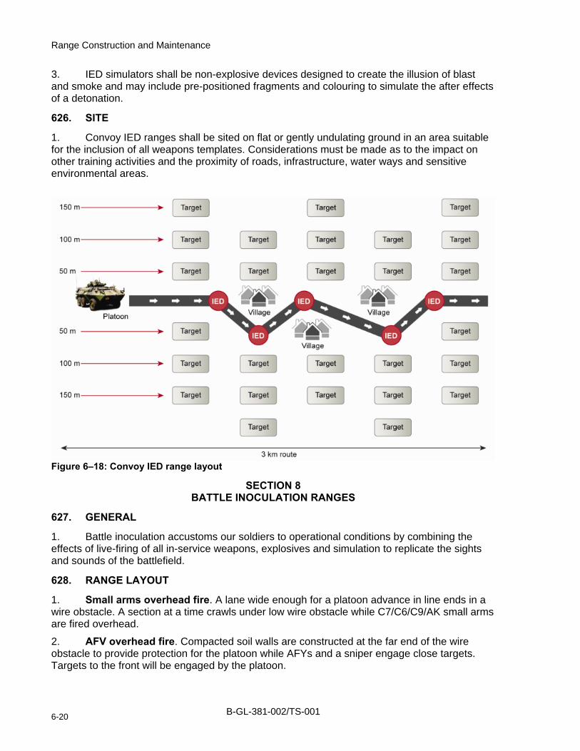
Range Construction and Maintenance
3. IED simulators shall be non-explosive devices designed to create the illusion of blast and smoke and may include pre-positioned fragments and colouring to simulate the after effects of a detonation.
626. SITE
1. Convoy IED ranges shall be sited on flat or gently undulating ground in an area suitable for the inclusion of all weapons templates. Considerations must be made as to the impact on other training activities and the proximity of roads, infrastructure, water ways and sensitive environmental areas.
Figure 6–18: Convoy IED range layout
SECTION 8 BATTLE INOCULATION RANGES
627. GENERAL
1. Battle inoculation accustoms our soldiers to operational conditions by combining the effects of live-firing of all in-service weapons, explosives and simulation to replicate the sights and sounds of the battlefield.
628. RANGE LAYOUT
1. Small arms overhead fire. A lane wide enough for a platoon advance in line ends in a wire obstacle. A section at a time crawls under low wire obstacle while C7/C6/C9/AK small arms are fired overhead.
2. AFV overhead fire. Compacted soil walls are constructed at the far end of the wire obstacle to provide protection for the platoon while AFYs and a sniper engage close targets. Targets to the front will be engaged by the platoon.
B-GL-381-002/TS-001 6-20

Training Facilities
3. Rocket propelled grenade simulation. Compacted soil walls extend in line to allow the platoon to advance to a point where the rocket propelled grenade (RPG) impact sounds initiate action. The platoon will seek protection between compacted soil walls while simulated explosions from an RPG impact in close proximity (via speaker system).
4. Improvised explosive device detonation. Light armoured vehicles (LAV) are positioned at the end of the compacted soil walls into which the platoon mounts. The LAVs advance along a short corridor and stop adjacent to a prepared BATSIM that is detonated to replicate an improvised explosive device (IED) explosion.
5. Artillery, mortar and close air fire. A corridor extends beyond the IED station through which a platoon is ordered to dismount, advance and clear the route. The loud speaker recording will simulate voice traffic from the fire support coordination centre (FSCC) to indicate enemy contact and call for fire support. Another series of compacted soil walls will afford protection to the troops who will take cover as a close air support mission is executed at danger close followed by artillery and mortar fire missions at danger close targets.
629. SITE
1. Battle inoculation ranges shall be sited on flat, well drained ground in an area suitable for the inclusion of all weapons templates. Considerations must be made as to the impact on other training activities and the proximity of roads, infrastructure, water ways and sensitive environmental areas.
B-GL-381-002/TS-001 6-21

Range Construction and Maintenance
Figure 6–19: Battle inoculation range
SECTION 9 FORWARD OPERATING BASES
630. GENERAL
1. A forward operating base (FOB) is a temporary facility that enables a unit or sub-unit element to command, act, sense, shield and sustain operations. The dimensions of a fob are dependant upon the size of the unit and related support elements. Construction methods are dependant upon the duration of stay and available construction. B-GL-361-012/FP-000 Accommodations, Installations and Engineering Services provides specific details as to regulations and codes to follow when engineer resources are to construct a FOB.
631. LAYOUT
1. Detailed layout will be dependant upon the mission of the tasked element and threat level and must take into consideration the types of threats that must be countered. Threats will include snipers, indirect rocket, artillery and mortar fire, chemical agents or suicide bombers.
B-GL-381-002/TS-001 6-22

Training Facilities
2. The schematic at figure 6–20 provides a generic layout and identifies the minimum operations, logistics and fighting emplacements. Consideration should be given to the construction of blast-proof walls to segment the compound thereby limiting the effects of blast and shrapnel weapons.
632. SITE
1. A fob may be located on any dominating ground that is relatively flat, well drained and provides unobstructed entrances and exits. Consideration should be made into incorporating the fob within the overall tactical scenario or a variety of training events and the potential impact the facility might have on other training activities.
2. Sites should be considered for their proximity to roads, infrastructure, water ways and to avoid sensitive environmental areas.
Figure 6–20: Forward operating base layout
B-GL-381-002/TS-001 6-23
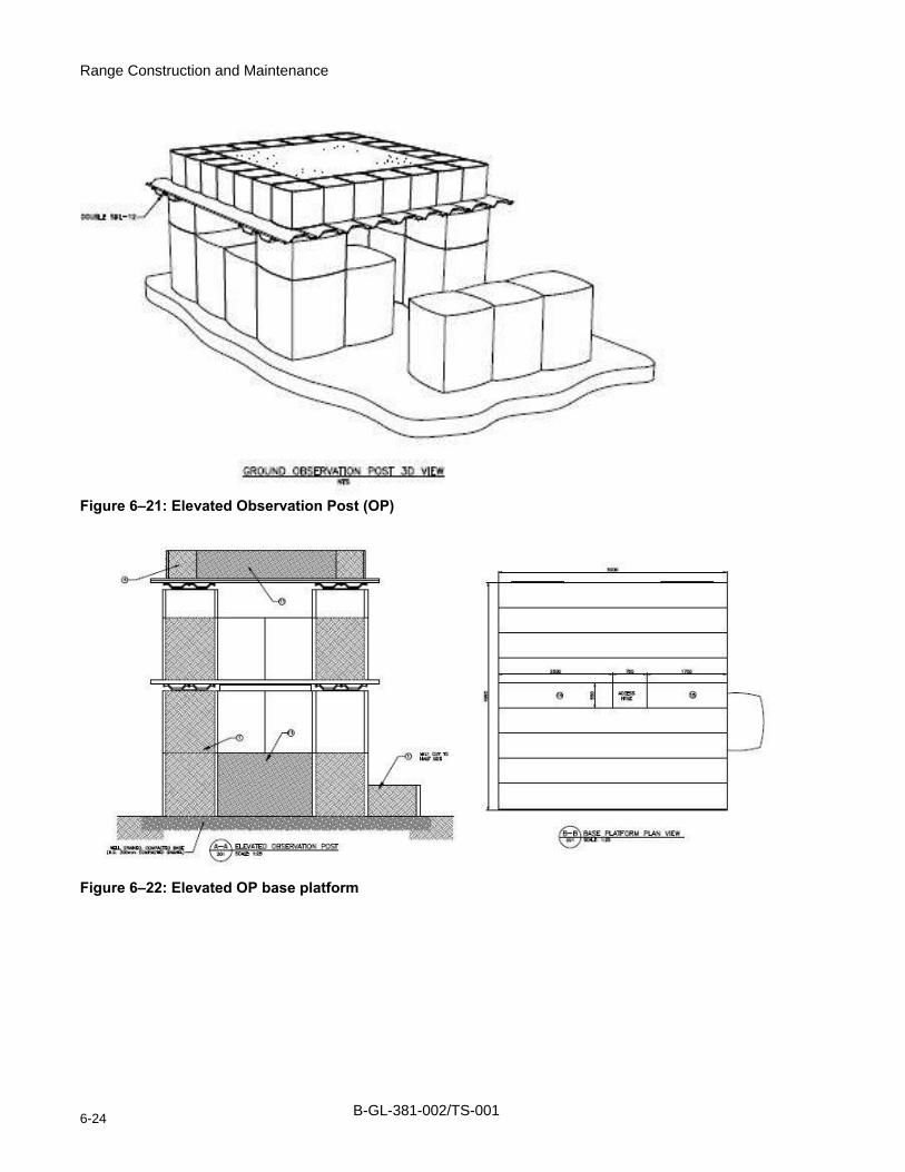
Range Construction and Maintenance
Figure 6–21: Elevated Observation Post (OP)
Figure 6–22: Elevated OP base platform
B-GL-381-002/TS-001 6-24
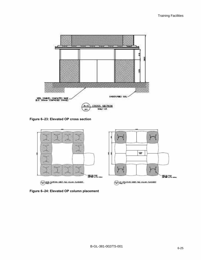
Training Facilities
Figure 6–23: Elevated OP cross section
Figure 6–24: Elevated OP column placement
B-GL-381-002/TS-001 6-25

Range Construction and Maintenance
Figure 6–25: Elevated OP floor plan
Figure 6–26: Elevated OP elevations
B-GL-381-002/TS-001 6-26

Training Facilities
Figure 6–27: Elevated OP outer lintel details
levated OP column assembly
Figure 6–28: E
B-GL-381-002/TS-001 6-27

Range Construction and Maintenance
Figure 6–29: Elevated OP base plate
B-GL-381-002/TS-001 6-28

Range Construction and Maintenance
ANNEX A TO CHAPTER 6 CONVENTIONAL SMALL ARMS RANGE INSPECTION CHECKLIST
1. Facility Name and Facility ID No:________________________________
2. Location: ___________________________________________________
3. Support Base: ________________________________________________
4. Area Command: ______________________________________________
5. Inspected By: ________________________________________________
6. Date of Inspection: _____________________________
Serial Description
Satis
fact
ory
Uns
atis
fact
ory
Uns
afe
N/A
a. Is a Copy of the CFRIS license posted in a conspicuous place?
1
b. Is it current, and does it accurately describe the type of weapons for which the range is to be used and pertinent limitations?
2 Are there any indications that the range is being used incorrectly, or that live firing is being conducted using weapons for which the range is not designed (as described in serial 1)?
a. Are approved range orders, as applicable, posted in a conspicuous location on the range and protected from the elements?
b. Are they complete and up-to-date?
3
c. Are danger area traces and templates available for the applicable weapons or, conversely, are danger areas illustrated on a map or scaled sketch of the range? (Chapter 2 of B-GL-381-001/TS-000 Training Safety)
a. Does new local construction, e.g. urban development, or change in the layout of the ranges (addition of new installations, new roads or tracks) in any way affect the present range boundaries or use of the range?
b. In the event of changes occurring (as described in 8a above), can danger area traces or templates still be applied to the range configuration and still assure adequate safety margins? (see appropriate Annex to Chapter 2 B-GL-381-001/TS-000 Training Safety)
4
c. Are arc markers on ranges clearly visible and correctly located?
B-GL-381-002/TS-001 6A-1

Range Construction and Maintenance
Serial Description
Satis
fact
ory
Uns
atis
fact
ory
Uns
afe
N/A
d. Can present danger areas be reduced further (by adjustments to the arcs or relocation of the firing points) on conventional ranges without decreasing the effectiveness of the range?
a. Is the present condition of the ground in the danger area (e.g. ice, frozen ground, excess undergrowth, unearthed boulders) likely to lead to a greater incidence of ricochets?
5
b. Should temporary limitations be placed on firing until the condition has been remedied or other corrective measures taken?
6 Are communication facilities in place, functioning and adequate, considering the layout, type of range and its location for the following:
a. the butts; b. sentry posts at access points on the range
boundaries; and
c. the Range Control and the range? 7 Are range boundaries clearly indicated by notice boards,
trespassing signs, RED flags or lights at access points and prominent locations as required by Chapter 1 of B-GL-304-003/TS-0A1?
8 Are warning and control flags and lights available in the correct sizes and colours for the various ranges?
9 Are warning systems, flags and lights serviceable? 10 Does thick undergrowth or tall grass affect visibility of target
areas or are they likely to present a fire hazard when firing?
11 Are restricted areas shown on all range control maps and are they up to date?
12 Are controls in effect to prevent live or spent ammunition being removed from the range by unauthorized personnel?
13 Are range clearance operations conducted? How often? By whom?
14 What is the level of training of personnel and what training is given prior to clearance operations?
15 Does Range Control or the supporting base have qualified personnel and staff for the destruction of duds and misfired ammunition?
16 Are duds reported and recorded and, if so, when are they destroyed and by whom?
B-GL-381-002/TS-001 6A-2

Annex A
Serial Description
Satis
fact
ory
Uns
atis
fact
ory
Uns
afe
N/A
17 What are range scrap disposal procedures and are they in accordance with B-GL-381-003/TS-000 Range Clearance?
18 Are containers available for spent casings and links? 19 If the range has a workshop area for weapon cleaning, target
storage, etc, is the entrance correctly signed, with sign DND 9905-21-855-4667 forbidding persons to take live ammunition inside?
20 Is fire fighting equipment available, in working order and regularly inspected?
21 Are cleaning solvents and oils placed in metal containers or metal lockups?
22 Are metal containers provided for oily rags? 23 Are heating appliances properly maintained and operating
instructions posted?
24 Are all firing points built according to specifications in B-GL-381-002/TS-000?
25 Are firing points separated by the required distances according to B-GL-381-001/TS-000 Training Safety?
26 Are troop shelters (incl. the butts), weapon pits, throwing bays or firing trenches etc, in serviceable condition and adequate for the protection of the numbers of personnel for which it is designed?
27 Are appropriate safety signs posted in administration areas as required according to B-GL-381-001/TS-000 Training Safety?
28 Is the range clear of debris and refuse and the grounds well maintained?
29 Are target frames serviceable? 30 Do target frames present a ricochet hazard (exposed metal
faced with 2.5cm wood)?
31 Are any construction flaws evident in the Marker’s Gallery? 32 Are benches in place and in good condition? 33 Is the mantlet built according to specifications in
B-GL-381-002/TS-000 Range Construction and Maintenance?
34 Is scooping evident on the mantlet? 35 Is there a suitable stop butt or bullet trap? 36 Is the stop butt built according to specifications in
B-GL-381-002/TS-000 Range Construction and Maintenance?
37 Is tunnelling evident and if so, does it exceed stop butt slope angles or minimum penetration requirements?
B-GL-381-002/TS-001 6A-3
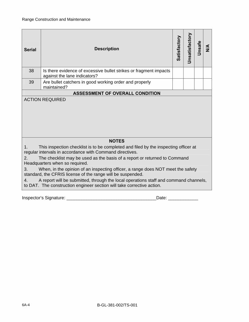
Range Construction and Maintenance
Serial Description
Satis
fact
ory
Uns
atis
fact
ory
Uns
afe
N/A
38 Is there evidence of excessive bullet strikes or fragment impacts against the lane indicators?
39 Are bullet catchers in good working order and properly maintained?
ASSESSMENT OF OVERALL CONDITION ACTION REQUIRED
NOTES 1. This inspection checklist is to be completed and filed by the inspecting officer at regular intervals in accordance with Command directives. 2. The checklist may be used as the basis of a report or returned to Command Headquarters when so required. 3. When, in the opinion of an inspecting officer, a range does NOT meet the safety standard, the CFRIS license of the range will be suspended. 4. A report will be submitted, through the local operations staff and command channels, to DAT. The construction engineer section will take corrective action.
Inspector’s Signature: ____________________________________Date: ____________
B-GL-381-002/TS-001 6A-4

Range Construction and Maintenance
ANNEX B TO CHAPTER 6 DEMOLITION RANGE CHECKLIST
1. Facility Name and Facility ID No:________________________________
2. Location: ___________________________________________________
3. Support Base: ________________________________________________
4. Area Command: ______________________________________________
5. Inspected By: ________________________________________________
6. Date of Inspection: _____________________________
Serial Description
Satis
fact
ory
Uns
atis
fact
ory
Uns
afe
N/A
1 Are the barriers and fencing in good order and are they properly marked with DND signage <<Danger Range Area >>?
2 Are the warning flags in good order, the right colours and in the right locations?
3 Is a copy of the CFRIS Authorization posted in a conspicuous location at the site and protected from the elements?
4 Are warning sign indicating a Demolition range visible and properly installed?
5 Are the Range Standing Orders up to date and do they reflect all requirements as posted in applicable safety and maintenance manuals?
6 Is the safety bunker in good condition and is the viewing port/glass clear with no cracking from fragmentation?
7 Is the fire fighting equipment available and in working condition?
8 Is the communication system in working order? Is there comms between the control bunker? The range entrance? Any strategic locations? And with range control?
B-GL-381-002/TS-001 6B-1

Range Construction and Maintenance
Serial Description
Satis
fact
ory
Uns
atis
fact
ory
Uns
afe
N/A
9 Are all trees, grasses and wooded materials removed from the detonation site for a 60m radius? Are all ricochet causing materials removed from the detonation site?
10 Are all craters filled in or raked at the end of an exercise?
11 Are the steel cutting areas clean and in order?
12 Are the concrete cutting areas clean and in order?
13 Are the mine warfare areas clean and in order?
14 Are the used materials and rubbish clean from the range regularly?
ASSESSMENT OF OVERALL CONDITION
ACTION REQUIRED
NOTES 1. This inspection checklist is to be completed and filed by the inspecting officer at regular intervals in accordance with Command directives.
2. The checklist may be used as the basis of a report or returned to Command Headquarters when so required.
3. When, in the opinion of an inspecting officer, a range does NOT meet the safety standard, the CFRIS license of the range will be suspended.
4. A report will be submitted, through the local operations staff and command channels, to DAT. The construction engineer section will take corrective action.
Inspector’s Signature: ________________________________Date: ____________
B-GL-381-002/TS-001 6B-2

Range Construction and Maintenance
ANNEX C TO CHAPTER 6 GALLERY (INDOOR) SMALL ARMS RANGE INSPECTION CHECKLIST
1. Facility Name and Facility ID No:________________________________
2. Location: ___________________________________________________
3. Support Base: ________________________________________________
4. Area Command: ______________________________________________
5. Inspected By: ________________________________________________
6. Date of Inspection: _____________________________
Serial Description of Item
Satis
fact
ory
Uns
atis
fact
ory
Uns
afe
N/A
a. Is a copy of the CFRIS licence posted in a conspicuous location at the site and protected from the elements?
1
b. Is it current, and does it accurately describe the type of weapons for which the range is to be used and pertinent limitations?
2 Are there any indications that the range is being used incorrectly, or that live firing is being conducted using weapons for which the range is not designed (as described in serial 1)?
a. Are approved range orders, as applicable, posted in a conspicuous location on the range?
b. Are they complete and up-to-date?
c. Are physical barriers barring access to the range area in good state of repair and signed with DANGER, FIRING RANGE?
d. Are warning signs posted?
e. Are Hearing Protection Required signs posted?
3
f. Are No Drinking/Eating signs posted?
g. Are Potential Lead Contamination Hazard signs posted?
h. Are No Smoking signs posted?
B-GL-381-002/TS-001 6C-1

Range Construction and Maintenance
Serial Description of Item
Satis
fact
ory
Uns
atis
fact
ory
Uns
afe
N/A
a. Is the Rounds Fired register up to date?
b. Is the Range Use register up to date?
c. Is the range inspected prior to firing?
d. Is the range inspected monthly, by a designated Range Safety Officer?
4
e. Is there a list of Range Safety Officers (RSO) posted and are they qualified in accordance with B-GL-381-001/TS-000 Training Safety?
a. Is First Aid equipment readily available during all firing exercises?
5
b. Is First Aid assistance available from qualified first aiders in accordance with CFAO 9-20?
Are controls in effect to prevent live or spent casings being removed from the range by unauthorized personnel:
a. Are spent casings collected and counted at the conclusion of firing?
b. Are unused live rounds collected and counted at the conclusion of firing?
c. Are fires and safety staff required to give a declaration at the conclusion of firing?
6
d. Are containers available for spent casings and are they periodically disposed of in accordance with CFP 181?
7 Is fire fighting equipment available, in good working order and regularly inspected?
8 Are cleaning solvents and oils (when storage facilities are provided on the range) placed in metal containers or metal lock-ups?
9 Are metal containers provided for oily rags?
B-GL-381-002/TS-001 6C-2

Annex C
Serial Description of Item
Satis
fact
ory
Uns
atis
fact
ory
Uns
afe
N/A
10 Are temperature control utilities or appliances properly maintained and are operating instructions posted?
11 Are the firing points safe, free of obstruction and covered in a non-absorbent, easily cleaned rest pad/mats that are in serviceable condition?
12 Are floors, walls and firing platforms cleaned using proper methods after each firing day?
13 Where pistols/revolvers are authorized, are firing stand or partitions available and in use?
14 Are all obstructions including lights, electrical fixtures and plumbing fixtures forward of the firing points on the side walls, ceilings and floors which are liable to cause ricochet or backsplash protected in accordance with B-GL-381-002/TS-000 Range Construction and Maintenance?
15 Are target frames in serviceable condition and functional?
16 Do target frames pose a ricochet hazard because of exposed metal?
17 What is the condition of the 7.5 cm wood facing?
18 What is the condition of the stop butt or bullet trap?
19 How well does the stop butt/bullet catch prevent ricochet and backsplash?
20 How effective is the sand mixture in the stop butt at containing rounds?
21 How well are the stop butts maintained through raking and sifting?
22 How effective is the maintenance routine in controlling tunnelling in the stop butt?
23 What is the condition of blackout painting on all down range surfaces?
B-GL-381-002/TS-001 6C-3

Range Construction and Maintenance
Serial Description of Item
Satis
fact
ory
Uns
atis
fact
ory
Uns
afe
N/A
24 How effective is the lighting system in providing proper levels of illumination?
25 Are air cleaners/filters in good working order, properly maintained and inspected?
26 Is the interior of the range acoustically treated to reduce noise levels?
27 If extra internal doors exist in the range, how effective is the locking system in controlling unauthorized access?
28 Is the range clear of debris and refuse and well maintained?
29 What is the status of use of personal respirators and disposable coveralls during range cleaning?
30 Are the methods used to clean the range in accordance with B-GL-381-002/TS-000 Range Construction and Maintenance?
ASSESSMENT OF OVERALL CONDITION
ACTION REQUIRED
B-GL-381-002/TS-001 6C-4

Annex C
Serial Description of Item
Satis
fact
ory
Uns
atis
fact
ory
Uns
afe
N/A
NOTES 1. This inspection checklist is to be completed and filed by the inspecting officer at regular intervals in accordance with Command directives.
2. The checklist may be used as the basis of a report or returned to Command Headquarters when so required.
3. When, in the opinion of an inspecting officer, a range does NOT meet the safety standard, the CFRIS license of the range will be suspended.
4. A report will be submitted, through the local operations staff and command channels, to DAT. The construction engineer section will take corrective action.
Inspector’s Signature: ____________________________________Date: ____________
B-GL-381-002/TS-001 6C-5


Range Construction and Maintenance
ANNEX D TO CHAPTER 6 GAS HUT INSPECTION CHECKLIST
1. Facility Name and Facility ID No:________________________________
2. Location: ___________________________________________________
3. Support Base: ________________________________________________
4. Area Command: ______________________________________________
5. Inspected By: ________________________________________________
6. Date of Inspection: _____________________________
Serial Description of Item
Satis
fact
ory
Uns
atis
fact
ory
Uns
afe
N/A
1 Is a copy of the CFRIS licence posted in a conspicuous location at the site and protected from the elements?
2 Do Range Standing Orders reflect all requirements as posted in applicable safety and maintenance manuals?
3 Is the facility secured with fencing and locked when not in use?
4 Are Chemical Warning and No Trespassing signs posted keeping unauthorized personnel out?
5 Is the emergency telephone or communications in location?
6 Is the gas hut located at least 100 m from the nearest building, road, waterway, vegetation or other area?
7 Is an electric hot plate, stove or heat source capable of temperatures in excess of 150o C in place?
8 Is a flat, metal container used to hold the agent during heating and dispersal?
9 Has the heat source been mounted on a stand or table at least 60 cm above floor level and protective covering been placed on nearby surfaces?
Notes: 1. Satisfactory: Divisible in three conditions: E: Excellent, G: Good, F: Fair.
2. Unsatisfactory: Damage to infrastructure causing undue damages.
3. Unsafe: Faults which could cause injury or death to personnel.
B-GL-381-002/TS-001 6D-1

Range Construction and Maintenance
Serial Description of Item
Satis
fact
ory
Uns
atis
fact
ory
Uns
afe
N/A
10 Is a fan placed to circulate the agent throughout the hut? This shall be placed on or near the floor to re-suspend and circulate the particles?
11 Has the gas hut been inspected by the fire department within the past 12 months?
12 Are warning signs posted outside the gas hut indicating: No open eating/drinking/smoking?
14 Are there separate entrance and exit doors with panic bars inside?
15 Are there any obstructions inside?
16 Is the gas hut cleaned?
17 Are ventilation exhaust fans of sufficient capacity installed and working?
18 Is there adequate lighting?
19 Is fire-fighting equipment available, in good working order, and regularly inspected?
20 Is the gas hut in serviceable condition?
21 Is there an indication that the gas hut is being used incorrectly (storage room, classroom, etc…)?
22 Is a prominently displayed red flag being used during gas hut training to indicate that the gas hut is in operation?
Notes: 1. Satisfactory: Divisible in three conditions: E: Excellent, G: Good, F: Fair.
2. Unsatisfactory: Damage to infrastructure causing undue damages.
3. Unsafe: Faults which could cause injury or death to personnel.
6D-2 B-GL-381-002/TS-001

Annex D
Serial Description of Item
Satis
fact
ory
Uns
atis
fact
ory
Uns
afe
N/A
ASSESSMENT OF OVERALL CONDITION
ACTION REQUIRED
NOTES 1. This inspection checklist is to be completed and filed by the inspecting officer at regular intervals in accordance with Command directives.
2. The checklist may be used as the basis of a report or returned to Command Headquarters when so required.
3. When, in the opinion of an inspecting officer, a range does NOT meet the safety standard, the CFRIS license of the range will be suspended.
4. A report will be submitted, through the local operations staff and command channels, to DAT. The construction engineer section will take corrective action.
Inspector’s Signature: ____________________________________Date: ____________
Notes: 1. Satisfactory: Divisible in three conditions: E: Excellent, G: Good, F: Fair.
2. Unsatisfactory: Damage to infrastructure causing undue damages.
3. Unsafe: Faults which could cause injury or death to personnel.
B-GL-381-002/TS-001 6D-3


Range Construction and Maintenance
ANNEX E TO CHAPTER 6 LIVE-FIRE SHOOT HOUSE INSPECTION CHECKLIST
1. Facility Name and Facility ID No:________________________________
2. Location: ___________________________________________________
3. Support Base: ________________________________________________
4. Area Command: ______________________________________________
5. Inspected By: ________________________________________________
6. Date of Inspection: _____________________________
Serial Description of Item
Satis
fact
ory
Uns
atis
fact
ory
Uns
afe
N/A
GENERAL INFORMATION
1 Does Range Control Standing Orders reflect all requirements as posted in applicable safety and maintenance manuals?
2a
2b
Does a proper template diagram exist for the facility?
If not, does a waiver exist and is it documented in the CFRIS pgm?
3a
3b
On initial inspection does the ricochet template interfere with any public access road networks? Are other activities (Mil/Civ) performed during a live fire shooting practice within the vicinity of the structure or within a ricochet template?
How many buildings/rooms make up this site? What size is the area encompassing the site? Is there an AAR building or structure in the vicinity?
4a
4b
Does Range Control hold a certificate from an engineering authority (since the last annual inspection) stating that all structures within the site have been inspected and are structurally sound?
X-ray/Scan of the AR500 walls and surfaces for structural integrity.
5a
5b
Is the structure(s) on a hard or soft prepared site?
Are any environmental test wells in place to monitor possible leeching?
B-GL-381-002/TS-001 6E-1

Range Construction and Maintenance
Serial Description of Item
Satis
fact
ory
Uns
atis
fact
ory
Uns
afe
N/A
SITE EXTERIOR
6a
6b
Is the site secured with fencing and locked when not in use? In the case of non-existent fencing, are all doors at the site locked?
Are warning signs posted, keeping unauthorized personnel out of the area when the site is in use?
7 Is the site clean and in good order? Are there signs of un-repaired training activities, e.g. holes, refuse, or salvage?
8 Is a copy of the CFRIS licence posted in a conspicuous location at the site and protected from the elements?
9 Is the license current and does it accurately describes the type of training for which the site is to be used and any restrictions listed?
10 Are there indications that the site is being used incorrectly?
11 Any undue damage has occurred due to misuse of the structures, e.g. bullet strikes to the outer walls?
12 Does the structure appear to be solid?
13 Are there signs of rust in any of the target bullet stops of the structure or bullet containment systems?
14 Are the bolts securing the main structure in place and tightly secured?
15 Are all doors and windows properly hinged and appear to be in good working condition?
16 Are there any signs of cracks, dimpling or faults on the outer shell of the structure?
17 Are all electronic devices installed and serviceable?
18 Is a tunnel system in place? Are access ports free and clear of debris?
B-GL-381-002/TS-001 6E-2

Annex E
Serial Description of Item
Satis
fact
ory
Uns
atis
fact
ory
Uns
afe
N/A
19 Are all sidewalks and prepared roadways in good condition without heaving/large cracks?
BUILDING/ROOM INTERIORS
20 Are there any signs of misuse of the buildings?
21 Is the interior clean and free of former training debris?
22 Are safety rails on stairwells secure and stable?
23 Are any surfaces susceptible to ricochets within the designated engagement height/area?
24 Is the building interior free of animal nests and feces?
25a
25b
Are all training aids (e.g. bullet traps) within the structure or storage areas in good condition and providing a purpose?
Are all rubber panels secured in place and in good condition?
UPPER LEVEL
26 Is there a ladder or stairwell provided to access upper walkway (catwalk)?
27 Are railings and anchors secured in place?
28 Is a serviceable warning system in place for the OIC Prac?
29 Does the upper structure provide a safe vantage point for the OIC at all entrances to the facility?
Is the catwalk structured in such a way as to allow the OIC Prac to remain behind active shooters throughout the range practice?
B-GL-381-002/TS-001 6E-3

Range Construction and Maintenance
Serial Description of Item
Satis
fact
ory
Uns
atis
fact
ory
Uns
afe
N/A
ASSESSMENT OF OVERALL CONDITION
ACTION REQUIRED
NOTES 1. This inspection checklist is to be completed and filed by the inspecting officer at regular intervals in accordance with Command directives.
2. The checklist may be used as the basis of a report or returned to Command Headquarters when so required.
3. When, in the opinion of an inspecting officer, a range does NOT meet the safety standard, the CFRIS license of the range will be suspended.
4. A report will be submitted, through the local operations staff and command channels, to DAT. The construction engineer section will take corrective action.
Inspector’s Signature: ____________________________________Date: ____________
B-GL-381-002/TS-001 6E-4

Range Construction and Maintenance
ANNEX F TO CHAPTER 6 SKEET & TRAP INSPECTION CHECKLIST
1. Facility Name and Facility ID No:________________________________
2. Location: ___________________________________________________
3. Support Base: ________________________________________________
4. Area Command: ______________________________________________
5. Inspected By: ________________________________________________
6. Date of Inspection: _____________________________
Serial Description
Satis
fact
ory
Uns
atis
fact
ory
Uns
afe
N/A
1 Are the barriers and fencing in good order and are they properly marked with DND signage <<Danger Range Area >>?
2 Is a copy of the CFRIS Authorization posted in a conspicuous location at the site and protected from the elements?
3 Is the CFRIS Authorization up to date and exact with respect to weapons and ammunition for this facility?
4 Are the Range Standing Orders up to date and do they reflect all requirements as posted in applicable safety and maintenance manuals?
5 Is the communications system in order and in contact with range control?
6 Is there any new construction in the area which could affect range safety?
7 Is the High house and Low house in good working order?
FIRING LINE
8 Are the shooting locations properly placed on the firing line?
9 Is there a shooting point located between the two houses?
B-GL-381-002/TS-001 6F-1

Range Construction and Maintenance
Serial Description
Satis
fact
ory
Uns
atis
fact
ory
Uns
afe
N/A
10 Are the shooting points well identified?
11 Are the shooting points level, dry and providing a stable firing point?
12 Are the firing points made of gravel or concrete?
13 Are the shooting pads a minimum 90 cm squared?
ADJACENT RANGES
14 Are there adjacent ranges?
15 If Yes, are they seperated by a fence or barrier?
16 Does the fence meet the 3.07 m height and 12.2 m length?
TRAP
17 Does the shooting points line of fire create an imaginary triangular point ahead of the range as described below?
18 Are the target throwers manual or automatic?
19 Are the floor dimensions at least 2.4 m square?
20 Are the target throwers properly protected from firing?
21 Are they constructed from cement or cider block?
22 Is there a sign indicating that movement is controlled by the RSO?
23 Is there a yellow flag at the trap operator position?
24 Are all shelters designated with signs preventing ammunition within?
B-GL-381-002/TS-001 6F-2

Annex F
Serial Description
Satis
fact
ory
Uns
atis
fact
ory
Uns
afe
N/A
ASSESSMENT OF OVERALL CONDITION
ACTION REQUIRED
NOTES 1. This inspection checklist is to be completed and filed by the inspecting officer at regular intervals in accordance with Command directives.
2. The checklist may be used as the basis of a report or returned to Command Headquarters when so required.
3. When, in the opinion of an inspecting officer, a range does NOT meet the safety standard, the CFRIS license of the range will be suspended.
4. A report will be submitted, through the local operations staff and command channels, to DAT. The construction engineer section will take corrective action.
Inspector’s Signature: ____________________________________Date: ____________
B-GL-381-002/TS-001 6F-3


Range Construction and Maintenance
ANNEX G TO CHAPTER 6 TRAINING AREA INSPECTION CHECKLIST
1. Facility Name and Facility ID No:________________________________
2. Location: ___________________________________________________
3. Support Base: ________________________________________________
4. Area Command: ______________________________________________
5. Inspected By: ________________________________________________
6. Date of Inspection: _____________________________
Serial Description of Item
Satis
fact
ory
Uns
atis
fact
ory
Uns
afe
N/A
1 Are there any indications that the training area is being used incorrectly?
Are field firing exercises being conducted in the area?
a. What types of weapons are used?
b. Are danger area traces and templates available for the applicable weapons or, conversely, are danger areas illustrated on a map?
c. Are arc markers clearly visible and correctly located?
d. Is every effort made to minimize contamination due to unexploded ammunition and to limit it to as small an area as possible?
2
e. Are procedures and regulations adequate to avoid environmental contamination of virgin land?
Are the control measures to clearly prohibit and discourage unauthorized entry to the ranges and training areas effective?
a. Are effective physical means such as fencing and signing of dangerous areas provided to preserve DND control of the areas?
b. Are the areas patrolled by security personnel with sufficient regularity?
3
c. Is public access controlled?
B-GL-381-002/TS-001 6G-1

Range Construction and Maintenance
Is the natural environment protected to the extent compatible with military requirement?
a. Is the training area clean and sanitary, e.g. not littered with garbage, barbed wire, empty POL containers?
b. Are defensive positions, trenches, obstacles, latrines, etc, filled or levelled in order to return the land to its original state?
4
c. Are bivouac areas clean, latrines and garbage areas properly filled and indicated?
5 Are physical barriers, fences, gates, signs, etc, in a good state of repair?
6 Are the fireguards properly located and maintained free of vegetation?
7 Are personnel shelters, targets, markers, training aids, etc, in serviceable condition?
ASSESSMENT OF OVERALL CONDITION
ACTION REQUIRED
NOTES 1. This inspection checklist is to be completed and filed by the inspecting officer at regular intervals in accordance with Command directives.
2. The checklist may be used as the basis of a report or returned to Command Headquarters when so required.
3. When, in the opinion of an inspecting officer, a range does NOT meet the safety standard, the CFRIS license of the range will be suspended.
4. A report will be submitted, through the local operations staff and command channels, to DAT. The construction engineer section will take corrective action.
Inspector’s Signature: ____________________________________Date: ____________
B-GL-381-002/TS-001 6G-2

Range Construction and Maintenance
ANNEX H TO CHAPTER 6 CEASS INSPECTION CHECKLIST
1. Facility Name and Facility ID No:________________________________
2. Location: ___________________________________________________
3. Support Base: ________________________________________________
4. Area Command: ______________________________________________
5. Inspected By: ________________________________________________
6. Date of Inspection: _____________________________
Serial Description of Item
Satis
fact
ory
Uns
atis
fact
ory
Uns
afe
N/A
1 Are physical barriers, barring access to the CEASS area, in a good state of repair and signed with “DANGER–CEASS IN PROGRESS”?
2 Are warning signs posted?
“HEARING PROTECTION REQUIRED” and “PERSONNEL PROTECTIVE EQUPMENT (PPE)”
3 Is the Command-approved Range/Training Area Authorization form (if applicable) posted in a conspicuous location on the range and protected from the elements?
4 Is the Area Fire Marshall (AFM) approved certificate available?
5 In the case of portable sites, are there indications that the site is being left assembled and used for long periods (more than 2 months)?
6 Is the site inspected prior to training activities? Firing?
7 Are Range Standing Orders available and up to date?
8 Is the Danger Area Overlay properly applied?
9 Are walls and doors in place and well fixed?
10 Are RSOs published in Routine Orders as per CFAO 9-20 and B-GL-381-001/TS-000? When were they Qualified?
11 Is the CEASS range inspected prior to use by the user?
B-GL-381-002/TS-001 6H-1

Range Construction and Maintenance
Serial Description of Item
Satis
fact
ory
Uns
atis
fact
ory
Uns
afe
N/A
12 Are all walls and doors securely installed?
13 Is a flag or signalling system in place?
14 Are all outer walls, roof and floors protected and free of ricochet causing obstructions?
15 Is first aid equipment available during all exercises?
16 How are other building occupants warned of firing status (live or not) (sound or verbal signal)?
17 Are fire fighting materials readily available and in good order (extinguishers routinely checked)?
18 Are any extra doors into the range area secured from the inside and checked by the RSO before firing commences?
ASSESSMENT OF OVERALL CONDITION
ACTION REQUIRED
B-GL-381-002/TS-001 6H-2

Annex H
Serial Description of Item
Satis
fact
ory
Uns
atis
fact
ory
Uns
afe
N/A
NOTES 1. This inspection checklist is to be completed and filed by the inspecting officer at regular intervals in accordance with Command directives.
2. The checklist may be used as the basis of a report or returned to Command Headquarters when so required.
3. When, in the opinion of an inspecting officer, a range does NOT meet the safety standard, the CFRIS license of the range will be suspended.
4. A report will be submitted, through the local operations staff and command channels, to DAT. The construction engineer section will take corrective action.
Inspector’s Signature: ____________________________________Date: ____________
B-GL-381-002/TS-001 6H-3


Range Construction and Maintenance
ANNEX I TO CHAPTER 6 OBSTACLE COURSE INSPECTION CHECKLIST
1. Facility Name and Facility ID No:________________________________
2. Location: ___________________________________________________
3. Support Base: ________________________________________________
4. Area Command: ______________________________________________
5. Inspected By: ________________________________________________
6. Date of Inspection: _____________________________
Serial Description of Item
Satis
fact
ory
Uns
atis
fact
ory
Uns
afe
N/A
1 Do Range Standing Orders/PSP Orders reflect all requirements as posted in applicable safety and maintenance manuals?
2 Does Range Control or PSP hold a certificate from an engineering authority stating that obstacle course has been inspected and the structures certified safe?
3 Is the facility secured with fencing and locked when not in use?
4 Are Warning Signs posted keeping unauthorized personnel out of the area?
5 Are emergency telephones or communications in location?
6 Is a copy of the CFRIS licence posted in a conspicuous location at the site?
OBSTACLES When checking obstacles, the following should be considered: tension devices, hooks, tie downs, clamps, partitions and walls, sharp edges, cracks/breaks, depressions/holes, surface condition, drop pit, pads/ filled, steel posts, supports posts, ladders, supports, hazardous items, drop zones, slippery surfaces, wood rot, splinters/iron shards, rubber surfaces, tree branches, nuts/bolts/nails etc.
Obst 1
Obst 2
B-GL-381-002/TS-001 6I-1

Range Construction and Maintenance
Serial Description of Item
Satis
fact
ory
Uns
atis
fact
ory
Uns
afe
N/A
Obst 3
Obst 4
Obst 5
Obst 6
Obst 7
Obst 8
Obst 9
Obst 10
Obst 11
Obst 12
Obst 13
ASSESSMENT OF OVERALL CONDITION
ACTION REQUIRED
B-GL-381-002/TS-001 6I-2

Annex I
Serial Description of Item
Satis
fact
ory
Uns
atis
fact
ory
Uns
afe
N/A
NOTES 1. This inspection checklist is to be completed and filed by the inspecting officer at regular intervals in accordance with Command directives.
2. The checklist may be used as the basis of a report or returned to Command Headquarters when so required.
3. When, in the opinion of an inspecting officer, a range does NOT meet the safety standard, the CFRIS license of the range will be suspended.
4. A report will be submitted, through the local operations staff and command channels, to DAT. The construction engineer section will take corrective action.
Inspector’s Signature: ____________________________________Date: ____________
B-GL-381-002/TS-001 6I-3


Range Construction and Maintenance
ANNEX J TO CHAPTER 6 RAPPEL TOWER INSPECTION CHECKLIST
1. Facility Name and Facility ID No:________________________________
2. Location: ___________________________________________________
3. Support Base: ________________________________________________
4. Area Command: ______________________________________________
5. Inspected By: ________________________________________________
6. Date of Inspection: _____________________________
Serial Description of Item
Satis
fact
ory
Uns
atis
fact
ory
Uns
afe
N/A
1 Do Range Standing Orders reflect all requirements as posted in applicable safety and maintenance manuals?
2 Does Range Control hold a certificate from an engineering authority stating that rappel tower has been inspected?
3 Is there an emergency telephone or communications in location?
4 Has a core sample been taken if the wooden structure is more than five years old?
GROUND LEVEL
5 Is the LZ covered with 400 mm sand type 1 and clear of any obstructions?
6 Is the facility secured with fencing and locked when not in use?
7 Are warning signs posted keeping unauthorized personnel out of the area?
8 Does the tower appear to be a solid structure?
9 Are there signs of rot around the tower base?
10 Are the bolts securing the main structure in place and tightly secured?
B-GL-381-002/TS-001 6J-1

Range Construction and Maintenance
Serial Description of Item
Satis
fact
ory
Uns
atis
fact
ory
Uns
afe
N/A
11 Are spacer blocks between support beams secure and in place?
12 Are support beams showing signs of aging, such as large cracks forming?
13 Is the planking of the rappel surfaces secure and free of nail/screw heads surfacing?
FIRST STATION
14 Is the ladder secure and is anti-slip tape in place if required?
15 Is the platform flat and free from potential hazards such as cupping planks and loose screws?
16 Are safety rails secure and stable?
17 Are safety chains installed across open areas when not in use?
18 Are rappel beams and anchors securely in place?
19 Is the edge of the rappel platform protected with anti-slip tape or other material (coco matting, rubber) and in good condition?
SECOND STATION
20 Is the ladder secure and is anti-slip tape in place if required?
21 Is the platform flat and free from potential hazards such as cupping planks and loose screws?
22 Are safety rails secure and stable?
23 Are safety chains installed across open areas when not in use?
24 Are rappel beams and anchors securely in place?
25 Is the edge of the rappel platform protected with anti-slip tape or other material (coco matting, rubber) and in good condition?
FREE-RAPPEL STATION
B-GL-381-002/TS-001 6J-2

Annex J
Serial Description of Item
Satis
fact
ory
Uns
atis
fact
ory
Uns
afe
N/A
26 Is the platform flat and free from potential hazards such as cupping planks and loose screws?
27 Is the edge of the rappel platform protected with anti-slip tape or other material (coco matting, rubber) and in good condition?
28 Are safety chains installed across open areas when not in use?
29 Is the metal skid correctly installed and secured?
30 Are all the anchors in place, correctly installed and secured?
31 Is a copy of the CFRIS licence posted in a conspicuous location at the site and protected from the elements?
32 Is there a flag pole in a prominent location?
ASSESSMENT OF OVERALL CONDITION
ACTION REQUIRED
NOTES 1. This inspection checklist is to be completed and filed by the inspecting officer at regular intervals in accordance with Command directives.
2. The checklist may be used as the basis of a report or returned to Command Headquarters when so required.
3. When, in the opinion of an inspecting officer, a range does NOT meet the safety standard, the CFRIS license of the range will be suspended.
4. A report will be submitted, through the local operations staff and command channels, to DAT. The construction engineer section will take corrective action.
B-GL-381-002/TS-001 6J-3

Range Construction and Maintenance
Inspector’s Signature: ____________________________________Date: ____________
B-GL-381-002/TS-001 6J-4
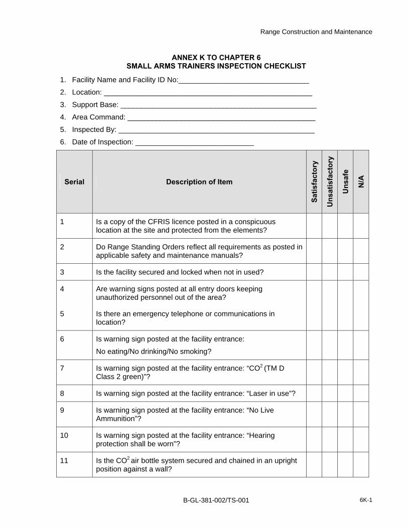
Range Construction and Maintenance
ANNEX K TO CHAPTER 6 SMALL ARMS TRAINERS INSPECTION CHECKLIST
1. Facility Name and Facility ID No:________________________________
2. Location: ___________________________________________________
3. Support Base: ________________________________________________
4. Area Command: ______________________________________________
5. Inspected By: ________________________________________________
6. Date of Inspection: _____________________________
Serial Description of Item
Satis
fact
ory
Uns
atis
fact
ory
Uns
afe
N/A
1 Is a copy of the CFRIS licence posted in a conspicuous location at the site and protected from the elements?
2 Do Range Standing Orders reflect all requirements as posted in applicable safety and maintenance manuals?
3 Is the facility secured and locked when not in used?
4 Are warning signs posted at all entry doors keeping unauthorized personnel out of the area?
5 Is there an emergency telephone or communications in location?
6 Is warning sign posted at the facility entrance:
No eating/No drinking/No smoking?
7 Is warning sign posted at the facility entrance: “CO2 (TM D Class 2 green)”?
8 Is warning sign posted at the facility entrance: “Laser in use”?
9 Is warning sign posted at the facility entrance: “No Live Ammunition”?
10 Is warning sign posted at the facility entrance: “Hearing protection shall be worn”?
11 Is the CO2 air bottle system secured and chained in an upright position against a wall?
B-GL-381-002/TS-001 6K-1

Range Construction and Maintenance
Serial Description of Item
Satis
fact
ory
Uns
atis
fact
ory
Uns
afe
N/A
12 Is the valve cover firmly closed when not in use?
13 Is the valve protective cover in place?
14 Is the CO2 detector in good order and situated at the firing point level?
15 Does the CO2 detector have the required/mandated visual and audio alarms installed and are they in good working order?
16 Is there adequate lighting?
17 Are the firing platforms in good condition?
18 Is the ventilation exhaust in order?
19 Is the Unit Safety Officer inspecting the facility monthly?
20 Are wires and cables laid out in a safe manner that avoids obstruction and tripping?
ASSESSMENT OF OVERALL CONDITION
ACTION REQUIRED
B-GL-381-002/TS-001 6K-2

Annex K
Serial Description of Item
Satis
fact
ory
Uns
atis
fact
ory
Uns
afe
N/A
NOTES 1. This inspection checklist is to be completed and filed by the inspecting officer at regular intervals in accordance with Command directives.
2. The checklist may be used as the basis of a report or returned to Command Headquarters when so required.
3. When, in the opinion of an inspecting officer, a range does NOT meet the safety standard, the CFRIS license of the range will be suspended.
4. A report will be submitted, through the local operations staff and command channels, to DAT. The construction engineer section will take corrective action.
Inspector’s Signature: ____________________________________Date: ____________
B-GL-381-002/TS-001 6K-3


Range Construction and Maintenance
ANNEX L TO CHAPTER 6 URBAN OPERATIONS TRAINING SYSTEM INSPECTION CHECKLIST
1. Facility Name and Facility ID No:________________________________
2. Location: ___________________________________________________
3. Support Base: ________________________________________________
4. Area Command: ______________________________________________
5. Inspected By: ________________________________________________
6. Date of Inspection: _____________________________
Serial Description of Item
Satis
fact
ory
Uns
atis
fact
ory
Uns
afe
N/A
GENERAL INFORMATION
1 Do Range Control Standing Orders reflect all requirements as posted in applicable safety and maintenance manuals?
2 Does Range Control hold a certificate from an engineering authority stating that all structures within the site have been inspected and are structurally sound?
3 How many buildings make up this site? What size is the area encompassing the site?
4 Does a proper template diagram exist for the facility?
SITE EXTERIOR
5 Is the site secured with fencing and locked when not in use. In the case of non-existent fencing, are all doors at the site locked?
6 Are warning signs posted, keeping unauthorized personnel out of the area when the site is in use?
7 Is the site clean and in good order? Are there signs of unrepaired training activities, e.g. holes, refuse and salvage?
8 Is a copy of the CFRIS licence posted in a conspicuous location at the site and protected from the elements?
B-GL-381-002/TS-001 6L-1

Range Construction and Maintenance
Serial Description of Item
Satis
fact
ory
Uns
atis
fact
ory
Uns
afe
N/A
9 Is the licence current and does it accurately describe the type of training for which the site is to be used and any restrictions listed?
10 Are there indications that the site is being used incorrectly?
11 Has any undue damage occurred due to misuse of the structures?
12 Does the structure appear to be solid?
13 Are there signs of rot in any of the wooden elements of the structure?
14 Are the bolts securing the main structure in place and tightly secured?
15 Are all doors and windows properly hinged and in good condition?
16 Are there any signs of major cracks or faults in the brick of the structures?
17 Are any rappel rails installed on the roof?
18 Is a tunnel system in place and access ports free and clear of debris?
19 Are all sidewalks and prepared roadways in good condition without heaving/large cracks?
BUILDING INTERIORS
20 Are there any signs of misuse of the buildings?
21 Is the interior clean and free of former training debris?
22 Are safety rails on stairwells secure and stable?
23 Are safety chains installed across open areas when not in use?
24 Is the building interior free of animal nests and feces?
B-GL-381-002/TS-001 6L-2

Annex L
Serial Description of Item
Satis
fact
ory
Uns
atis
fact
ory
Uns
afe
N/A
25 Are all furniture/training aids within the structure in good condition and serving their intended purpose?
UPPER LEVEL / ROOF TOP
26 Is there a ladder provided to enter the attic?
27 Are rappel beams and anchors securely in place?
ASSESSMENT OF OVERALL CONDITION
ACTION REQUIRED
NOTES 1. This inspection checklist is to be completed and filed by the inspecting officer at regular intervals in accordance with Command directives.
2. The checklist may be used as the basis of a report or returned to Command Headquarters when so required.
3. When, in the opinion of an inspecting officer, a range does NOT meet the safety standard, the CFRIS license of the range will be suspended.
4. A report will be submitted, through the local operations staff and command channels, to DAT. The construction engineer section will take corrective action.
Inspector’s Signature: ____________________________________Date: ____________
B-GL-381-002/TS-001 6L-3


Range Construction and Maintenance
ANNEX M TO CHAPTER 6 REDUCED TEMPLATE BAFFLE RANGE CHECK LIST
1. Facility Name and Facility ID No:________________________________
2. Location: ___________________________________________________
3. Support Base: ________________________________________________
4. Area Command: ______________________________________________
5. Inspected By: ________________________________________________
6. Date of Inspection: _____________________________
Serial Description
Satis
fact
ory
Uns
atis
fact
ory
Uns
afe
N/A
1 Are the barriers and fencing in good order and are they properly marked with DND signage <<Danger Range Area >>?
2 Is a copy of the CFRIS Authorization posted in a conspicuous location at the site and protected from the elements?
3 Is the license current and are all weapons and ammunitions information’s correct and restrictions shown?
4 Are the Range Standing Orders up to date and do they reflect all requirements as posted in applicable safety and maintenance manuals?
5 Is there proper communication means available between RC and the range?
6 Is there any new construction or development which impacts this facility?
7 Are the Arc markers clearly visible and in the right position?
8 Are there any signs the range is being used incorrectly or with unauthorized ammunitions?
9 Is the bullet catch free of ricochet materials and properly maintained?
B-GL-381-002/TS-001 6M-1

Range Construction and Maintenance
Serial Description
Satis
fact
ory
Uns
atis
fact
ory
Uns
afe
N/A
10 Are there any unsafe temporary repairs?
11 Are the range boundaries properly marked with approved signage?
12 Is the range properly marked with appropriately coloured Range flags or a lighting system as per B-GL-381-002/TS-000 guide lines?
13 Are the flags or light system in good condition?
14 Is the range facility properly maintained? How often? And by who?
15 Is fire fighting equipment available and in good order? Has it been regularly inspected as per fire orders?
16 Are cleaning materials kept in order and inside of a proper metal storage system?
17 Is there a fire rated metal refuse container for all used cleaning materials?
18 Is all heating equipment kept in good order and operating instruction posted?
19 Are target frames in good order?
20 Are there any ricochet hazards present?
21 Is there a stop butt and bullet recovery system, and is it in good order?
22 Are bullets and bullet materials regularly cleaned out of the bullet catch system? How often? By whom?
23 Are there signs of tunnelling in the stop butt/ bullet catch?
24 Are all shooting points in good order?
25 Are all troop sheltering locations in good order? Do they provide protection from the elements and from firing
B-GL-381-002/TS-001 6M-2

Annex L
Serial Description
Satis
fact
ory
Uns
atis
fact
ory
Uns
afe
N/A
where required?
26 Are all lighting systems in working condition and in good order?
27 Are spare bulbs available, and is the wiring damage free?
28 Is there a recycling program for casings and bullets? What is it?
29 Are all troop shelters properly signed with << No live munitions inside this building>> signs as described in the manual? Sign MDN 9905-21-855-4667 is the standard.
GENERAL COMMENTS
ACTION REQUIRED
NOTES 1. This inspection checklist is to be completed and filed by the inspecting officer at regular intervals in accordance with Command directives.
2. The checklist may be used as the basis of a report or returned to Command Headquarters when so required.
3. When, in the opinion of an inspecting officer, a range does NOT meet the safety standard, the CFRIS license of the range will be suspended.
4. A report will be submitted, through the local operations staff and command channels, to DAT. The construction engineer section will take corrective action.
Inspector’s Signature: ____________________________________Date: ____________
B-GL-381-002/TS-001 6M-3


Range Construction and Maintenance
ANNEX N TO CHAPTER 6 RANGE CONTROL AGENCY CHECKLIST
1. Facility Name and Facility ID No:________________________________
2. Location: ___________________________________________________
3. Support Base: ________________________________________________
4. Area Command: ______________________________________________
5. Inspected By: ________________________________________________
6. Date of Inspection: _____________________________
Serial Description of Item Comments 1 Is the Base Control Agency manned to
perform its task?
a. Are the personnel properly trained and properly supervised?
b. Are the personnel duly qualified to perform their functions?
2 Are the following functions performed adequately?
a. allocation of individual ranges to users;
b. preparation and promulgation of range schedules;
c. preparation, review, amending and promulgation of range standing orders;
d. marking the ranges and issuing press notices of firing when required; and
e. compiling and maintaining accurate range records containing the following data:
(1) use of range by unit, weapon ammunition nature and number of rounds fired;
(2) exact location and marking of located but undestroyed duds;
(3) suspected location of other undestroyed duds; and
Notes: 1. Satisfactory: Divisible in three conditions: E: Excellent, G: Good, F: Fair.
2. Unsatisfactory: Damage to infrastructure causing undue damages.
3. Unsafe: Faults which could cause injury or death to personnel.
B-GL-381-002/TS-001 6N-1

Range Construction and Maintenance
Serial Description of Item Comments (4) location and marking of safe
routes.
3 Is the communication system on ranges and training areas used for live firing exercises working adequately?
4 Are the following emergency systems adequate and are they tested occasionally?
a. Medical? b. Fire-fighting? c. Recovery?
5 Is the general maintenance of the ranges and training areas adequately coordinated by the range control agency?
6 Are range and training area inspections carried out at regular intervals?
7 Are actions taken to ensure users conduct immediate post-firing range sweeps?
8 Is the system used for the destruction of any duds reported in the Ammunition Control Certificate, Figure 1–3 of B-GL-381-001/TS-000, effective?
9 Are the ranges and training areas patrolled on a regular basis?
10 Are the impact areas, ranges and training areas, classified by types corresponding with the information stated in the Range/Training Area Authorization Form in accordance with B-GL-381-002/TS-000?
11 Is the Range Development Plan current? 12 Is the Range Clearance Plan current?
GENERAL COMMENTS ACTION REQUIRED
Notes: 1. Satisfactory: Divisible in three conditions: E: Excellent, G: Good, F: Fair.
2. Unsatisfactory: Damage to infrastructure causing undue damages.
3. Unsafe: Faults which could cause injury or death to personnel.
6N-2 B-GL-381-002/TS-001

Annex N
Serial Description of Item Comments NOTES
1. This inspection checklist is to be completed and filed by the inspecting officer at regular intervals in accordance with Command directives. 2. The checklist may be used as the basis of a report or returned to Command Headquarters when so required. 3. When, in the opinion of an inspecting officer, a range does NOT meet the safety standard, the CFRIS license of the range will be suspended. 4. A report will be submitted, through the local operations staff and command channels, to DAT. The construction engineer section will take corrective action.
Inspector’s Signature: ____________________________________Date: ____________
Notes: 1. Satisfactory: Divisible in three conditions: E: Excellent, G: Good, F: Fair.
2. Unsatisfactory: Damage to infrastructure causing undue damages.
3. Unsafe: Faults which could cause injury or death to personnel.
B-GL-381-002/TS-001 6N-3


Range Construction and Maintenance
ANNEX O TO CHAPTER 6 GRENADE RANGE INSPECTION CHECKLIST
1. Facility Name and Facility ID No:________________________________
2. Location: ___________________________________________________
3. Support Base: ________________________________________________
4. Area Command: ______________________________________________
5. Inspected By: ________________________________________________
6. Date of Inspection: _____________________________
Serial Description
Satis
fact
ory
Uns
atis
fact
ory
Uns
afe
N/A
INFORMATION GÉNÉRALE
1 Do range control standing orders reflect all requirements as posted in applicable safety and maintenance manuals?
2 Does range control hold a certificate from an engineering authority stating that all structures within the site have been inspected and are structurally sound?
3 Is a copy of the CFRIS license posted in a conspicuous location at the site?
4 Is the license current and are all weapons and ammunitions information’s correct and restrictions shown?
5 Is there a controlled area marked to indicate the appropriate template?
6 Is there proper communication means available between Range Control and the range?
7 Is there fire fighting equipment readily available to the user and in working condition?
SITE EXTERIOR
8 Are all gates installed and is signage posted indicating hazards?
9 If the range is not in a secure location are locks in place and functional restricting access?
10 Are range boundaries clearly indicated by notice boards, trespassing signs, RED flags or lights at access points and prominent locations as required?
Notes: 1. Satisfactory: Divisible in three conditions: E: Excellent, G: Good, F: Fair.
2. Unsatisfactory: Damage to infrastructure causing undue damages.
3. Unsafe: Faults which could cause injury or death to personnel.
B-GL-381-002/TS-001 6O-1

Range Construction and Maintenance
Serial Description
Satis
fact
ory
Uns
atis
fact
ory
Uns
afe
N/A
11 Is the site clean and in good order? Are there signs of unrepaired training activities, e.g. holes, refuse, or salvage?
12 Is the impact area clear of rocks and other debris? 13 Has the impact area been raked after use? 14 Is the impact area clear of any impact craters?
CONTROL TOWER
15 Are the stairs clean and in good condition? Are all ricochet surfaces covered?
16 Are the hand rails secure and in good condition? 17 Is the entrance to the tower secure with a functional lock? 18 Is the door functional and all hinges in place? 19 Are there any signs of rot on the wooden structure?
20 Is a communication device in place to the throwing bays and is it functional.
21 Are all security glass surfaces in good condition and built IAW the maintenance manual?
22 Is the entrance to the tower correctly signed with DND 9905-21-855-4667 forbidding persons to take live munitions in the tower?
23 Are the tower flags correctly mounted and in good condition? 24 Is the overall condition of the tower adequate?
THROWING BAYS 25 Are the bays constructed IAW the maintenance manual?
26 Are the protective wooden layers in good condition and to proper specifications?
27 Are the walls clear of any obstructions? 28 Are the viewing ports built to standard and in good condition?
PREPARATION BAY 29 Is the bay built IAW the manual and clean?
30 Are there any obstructions in the bay preventing safe passage?
WAITING BAY
Notes: 1. Satisfactory: Divisible in three conditions: E: Excellent, G: Good, F: Fair.
2. Unsatisfactory: Damage to infrastructure causing undue damages.
3. Unsafe: Faults which could cause injury or death to personnel.
6O-2 B-GL-381-002/TS-001

Annex O
Serial Description
Satis
fact
ory
Uns
atis
fact
ory
Uns
afe
N/A
28 Is the bay constructed IAW the maintenance manual?
29 Are there any obstructions in the bay preventing safe passage?
30 Are all viewing stations in good condition and built to specification?
31 Are the wooden surfaces in good condition and built to specification?
32 Are all doors in good condition and working properly?
33 Is the entrance to the waiting bay correctly signed with DND 9905-21-855-4667 forbidding persons to take live munitions in the tower?
TROOP SHELTER
34 Is the entrance to the troop shelter correctly signed with DND 9905-21-855-4667 forbidding persons to take live munitions in the tower?
35 Is the heating system in place and properly working? 36 Are all doors and windows in good order? 37 Are all lighting systems in good working order?
OVERALL CONDITION ASSESMENT ACTION REQUIRED
Notes: 1. Satisfactory: Divisible in three conditions: E: Excellent, G: Good, F: Fair.
2. Unsatisfactory: Damage to infrastructure causing undue damages.
3. Unsafe: Faults which could cause injury or death to personnel.
B-GL-381-002/TS-001 6O-3

Range Construction and Maintenance
Serial Description
Satis
fact
ory
Uns
atis
fact
ory
Uns
afe
N/A
NOTES 1. This inspection checklist is to be completed and filed by the inspecting officer at regular intervals in accordance with Command directives. 2. The checklist may be used as the basis of a report or returned to Command Headquarters when so required. 3. When, in the opinion of an inspecting officer, a range does NOT meet the safety standard, the CFRIS license of the range will be suspended. 4. A report will be submitted, through the local operations staff and command channels, to DAT. The construction engineer section will take corrective action.
Inspector’s Signature: ____________________________________Date: ____________
Notes: 1. Satisfactory: Divisible in three conditions: E: Excellent, G: Good, F: Fair.
2. Unsatisfactory: Damage to infrastructure causing undue damages.
3. Unsafe: Faults which could cause injury or death to personnel.
6O-4 B-GL-381-002/TS-001

Range Construction and Maintenance
CHAPTER 7 GLOSSARY AND DEFINITIONS
Active—RTA that is used for the conduct of military activities.
Ammunition—a loaded cartridge consisting of a primer, propellant and projectile.
Austere range—A simplistic range, low in cost and of temporary status.
Authority—the power to issue orders and make decisions. An expert whose views are taken as definitive.
Ballistics—the science of flight dynamics including the trajectory of an object in free flight.
Blast—concussion, an explosion.
Blast-proof—impervious, not admitting of passage or capable of being affected, i.e. nullifying the concussive effects of the blast wave.
Bullet splash—the spatter and fragmentation of a bullet upon impacting a hard surface.
Bullet trap—a safe means of stopping a projectile in flight when recovering the projectile is not required.
Bunker—a reinforced shelter located above or below ground which is impervious to blast and splinters.
Cartridge—a single unit of ammunition consisting of the case, primer and propellant with or without a projectile.
Closed—RTA that remains in the DND inventory but which is not used for military activities.
Condition—assessed state of maintenance and safety expressed as red, yellow, green or purple.
Confidence course—(see obstacle course). An obstacle course employed to encourage each participant to surmount a series of challenging situations. The primary intent is to develop individual self-reliance and confidence in individual and team capabilities.
Conventional range—a permanent facility with fixed firing points, a fixed firing axis and danger area which may include a stop butt, target frames, target system and usually includes a marker’s gallery and ancillary buildings (ablutions, range hut, target shed, etc.).
Danger area—The danger area is the area associated with a range from which unauthorized ships, personnel, equipment, and aircraft are excluded for reasons of safety, either because of the actual firing of weapons or the presence in the ground of unexploded mines or other munitions.
Danger area template—Each specific weapon and ammunition combination has a distinct danger area template. This template is the area describing the danger area of a single weapon firing that ammunition on a fixed line.
Decommissioned—Facilities, structures and plant that have been physically removed and/or destroyed, the terrain has been cleaned and all pollutants removed or neutralized. The RTA or facility is awaiting disposal and the license will have been archived.
B-GL-381-002/TS-001 7-1
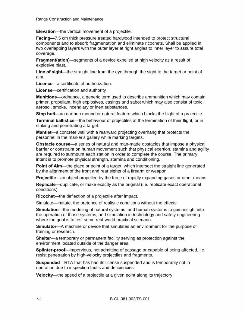
Range Construction and Maintenance
Elevation—the vertical movement of a projectile. Facing—7.5 cm thick pressure treated hardwood intended to protect structural components and to absorb fragmentation and eliminate ricochets. Shall be applied in two overlapping layers with the outer layer at right angles to inner layer to assure total coverage. Fragment(ation)—segments of a device expelled at high velocity as a result of explosive blast. Line of sight—the straight line from the eye through the sight to the target or point of aim. Licence—a certificate of authorization. License—certification and authority Munitions—ordnance, a generic term used to describe ammunition which may contain primer, propellant, high explosives, casings and sabot which may also consist of toxic, aerosol, smoke, incendiary or inert substances. Stop butt—an earthen mound or natural feature which blocks the flight of a projectile. Terminal ballistics—the behaviour of projectiles at the termination of their flight, or in striking and penetrating a target. Mantlet—a concrete wall with a rearward projecting overhang that protects the personnel in the marker’s gallery while marking targets. Obstacle course—a series of natural and man-made obstacles that impose a physical barrier or constraint on human movement such that physical exertion, stamina and agility are required to surmount each station in order to complete the course. The primary intent is to promote physical strength, stamina and conditioning. Point of Aim—the place or point of a target, which intersect the straight line generated by the alignment of the front and rear sights of a firearm or weapon. Projectile—an object propelled by the force of rapidly expanding gases or other means. Replicate—duplicate, or make exactly as the original (i.e. replicate exact operational conditions) Ricochet—the deflection of a projectile after impact. Simulate—imitate, the pretence of realistic conditions without the effects. Simulation—the modeling of natural systems, and human systems to gain insight into the operation of those systems; and simulation in technology and safety engineering where the goal is to test some real-world practical scenario. Simulator—A machine or device that simulates an environment for the purpose of training or research. Shelter—a temporary or permanent facility serving as protection against the environment located outside of the danger area. Splinter-proof—impervious, not admitting of passage or capable of being affected, i.e. resist penetration by high-velocity projectiles and fragments.
Suspended—RTA that has had its license suspended and is temporarily not in operation due to inspection faults and deficiencies.
Velocity—the speed of a projectile at a given point along its trajectory.
7-2 B-GL-381-002/TS-001