recommendations of the american association of physicists in
TRANSCRIPT
Recommendations of the American Association of Physicists in Medicine ondosimetry, imaging, and quality assurance procedures for 90Y microspherebrachytherapy in the treatment of hepatic malignancies
William A. DezarnMedical Radiation Physics Inc., Milford, Ohio 45150
Jeffery T. CessnaPhysics Laboratory, National Institute of Standards and Technology, Gaithersburg,Maryland 20899
Larry A. DeWerdDepartment of Medical Physics, University of Wisconsin-Madison, Madison, Wisconsin 53705
Wenzheng FengHeart and Vascular Center, Cardiology and Interventional Radiology, William Beaumont Hospital,Royal Oak, Michigan 48073
Vanessa L. GatesDivision of Interventional Radiology, Department of Radiology, Northwestern Memorial Hospital, Chicago,Illinois 60611
James HalamaLoyola University Medical Center, Maywood, Illinois 60153
Andrew S. KennedyWake Radiology Oncology Services, Cary, North Carolina 27518
Subir NagKaiser Permanente Radiation Oncology, Santa Clara, California 95051
Mehrdad SarfarazDepartment of Radiation Oncology, Greater Baltimore Medical Center, Baltimore, Maryland 21204
Varun SehgalDepartment of Radiation Oncology, University of California, Irvine Medical Center, Orange,California 92868
Reed SelwynRadiology and Radiological Sciences Department, Uniformed Services University of the Health Sciences,Bethesda, Maryland 20814
Michael G. StabinDepartment of Radiology and Radiological Sciences, Vanderbilt University, Nashville,Tennessee 37232
Bruce R. ThomadsenDepartment of Medical Physics, University of Wisconsin-Madison, Madison, Wisconsin 53705
Lawrence E. WilliamsRadiology, City of Hope Medical Center, Duarte, California 91010
Riad SalemDivision of Interventional Radiology, Department of Radiology, Northwestern Memorial Hospital, Chicago,Illinois 60611
(Received 8 April 2011; revised 16 June 2011; accepted for publication 17 June 2011;
published 1 August 2011)
Yttrium-90 microsphere brachytherapy of the liver exploits the distinctive features of the liver anat-
omy to treat liver malignancies with beta radiation and is gaining more wide spread clinical use.
This report provides a general overview of microsphere liver brachytherapy and assists the treat-
ment team in creating local treatment practices to provide safe and efficient patient treatment. Sug-
gestions for future improvements are incorporated with the basic rationale for the therapy and
currently used procedures. Imaging modalities utilized and their respective quality assurance are
discussed. General as well as vendor specific delivery procedures are reviewed. The current dosim-
etry models are reviewed and suggestions for dosimetry advancement are made. Beta activity stand-
ards are reviewed and vendor implementation strategies are discussed. Radioactive material
licensing and radiation safety are discussed given the unique requirements of microsphere brachy-
therapy. A general, team-based quality assurance program is reviewed to provide guidance for the
4824 Med. Phys. 38 (8), August 2011 0094-2405/2011/38(8)/4824/22/$30.00 VC 2011 Am. Assoc. Phys. Med. 4824
creation of the local procedures. Finally, recommendations are given on how to deliver the current
state of the art treatments and directions for future improvements in the therapy. VC 2011 AmericanAssociation of Physicists in Medicine. [DOI: 10.1118/1.3608909]
Key words: yttrium, microsphere, brachytherapy, radioembolization, liver, dosimetry, imaging
I. INTRODUCTION
Yttrium-90 microsphere brachytherapy of liver cancers takes
advantage of the unique vascular system of the liver. In nor-
mal liver tissue, approximately 70%–80% of the organ’s
blood flow is supplied by the portal vein, and the hepatic ar-
tery accounts for the rest. This contrasts with both hepatocel-
lular carcinoma (HCC) and metastatic tumors in the liver,
which have approximately 80%–100% of their blood flow
supplied by the hepatic artery.1 This difference in perfusion
is exploited by microsphere brachytherapy, whereby, radio-
active microspheres doped with a beta-emitting radionuclide
are used to both embolize and irradiate tumors in the liver by
delivering the microspheres through the hepatic artery to
selectively target malignant disease.
In contrast, the key limitation in any application of exter-
nal beam radiation to the liver is the lower tolerance of nor-
mal liver parenchyma to radiation compared to the dose
required to destroy tumors.2 The maximum external beam
acceptable dose to the whole liver of 35 Gy delivered in 1.8
Gy=day fractions3 is far below that which is required to
destroy solid tumor lesions, estimated at greater than 70 Gy.4
Therefore, patients selected for conformal external beam
radiation therapy must have tumors that are well defined on
CT or MR and the ability to treat safely is limited by lesion
number, distribution, and location. Microsphere brachyther-
apy provides an alternative means of treatment for patients.
Treatment with 90Y microspheres is based on cross-sec-
tional images and arteriograms for each patient. The work-
up includes triple-phase contrast CT and=or contrast
enhanced magnetic resonance (MR) imaging of the liver for
assessment of tumor and nontumor volumes, portal vein pat-
ency, and extent of extrahepatic disease. Serum chemical
analyses evaluate hepatic and renal function and determine
the presence and magnitude of elevation of tumor markers.
The clinical practice guideline recommendations for 90Y
microsphere brachytherapy were recently published by the
Radioembolization Brachytherapy Oncology Consortium
(REBOC).5 The procedure entails the injection of embolic
particles loaded with a radionuclide using transvascular
approaches. There are two components to the procedure:
(1) Embolization: injection of permanent embolic particles
and vessel embolization, and
(2) Brachytherapy: delivery of the brachytherapy device
(e.g., resin or glass microspheres).
It should be noted that different disciplines use slightly
different names for this procedure. From the brachytherapy
perspective, the terms microsphere brachytherapy and the
microbrachytherapy are used. Here, the emphasis is on the
permanent radioactive implant component of the procedure.
Interventional radiology uses the term radioembolization
which emphasizes the embolization procedures they typi-
cally perform. The practitioners of this procedure should be
aware of the differences both in discipline and in practical
use. The term microsphere brachytherapy will be used in this
report.
I.A. Microsphere rationale
The delivery of radioactive microparticles by a patient’s
vasculature dates back to the 1940s, however, the use of
microspheres embedded with a beta-emitting radionuclide,
typically 90Y, has only become clinically relevant since the
middle-1980s. Kennedy et al.6 provide a comprehensive
review of radioactive microsphere development and utiliza-
tion. As stated earlier, the hepatic artery also preferentially
provides tumors with their blood flow. Thus, the hepatic ar-
tery provides a natural pathway to tumor cells, while largely
missing normal liver cells.
Currently, two 90Y-microsphere products are available
commercially worldwide: one is composed of 90Y doped
resin (SIR-SpheresVR
; Sirtex Medical Limited, North Sydney,
Australia) and the other incorporates 90Y in a glass matrix
(TheraSphereVR
; Nordion Inc., Ottawa, Canada) (see Table I).
Neither type of microsphere demonstrates leaching of 90Y at
levels considered potentially important. Erbe and Day7 pres-
ent data for glass microspheres while the SIR-SpheresVR
User
Manual notes that trace amounts of radioactivity, 25–50 kBq
TABLE I. Properties of commercially available 90Y microspheres.
Description item SIR-SpheresVR
TheraSphereVR
Sphere material Resin Glass
Sphere diameter
(lm)
20–60 20–30
Activity in single
vial (GBq)
3 six sizes: 3, 5, 7, 10,
15, and 20
Number of spheres
per vial
40–80� 106 six sizes: 1.2–8� 106
Density (g=cm3) 1.6 3.29a)
90Y activation mode Carrier-free Reactor
Assumed activity per
sphere (Bq)
50 2500
Shelf life 24 h after
calibration
12 days after
calibration90Y average decay
energy
0.9267 MeV per disintegration
90Y half-life 2.6684 days
a)US Patent 5,302,369.
4825 Dezarn et al.: AAPM recommendations 90Y microsphere brachytherapy 4825
Medical Physics, Vol. 38, No. 8, August 2011
L�1 per GBq delivered, have been detected in patient urine
in the past.
Most often, the clinical indication for using microsphere
brachytherapy is colon adenocarcinoma metastatic to the
liver persisting despite optimal chemotherapy. Patients with
primary HCC are also eligible to be treated with micro-
spheres. Clinical experiences in a number of centers have
demonstrated the safety, efficacy, and preferred methodolog-
ical techniques of the microsphere therapy.5,8–12 However,
unlike procedures that use sealed sources common to
brachytherapy (137Cs, 103Pd, 125I, etc.), the activity and total
number of individual sources cannot be verified uniquely for90Y microspheres. No standardized methods in microsphere
brachytherapy exist for source activity measurement inde-
pendent of the manufacturers. Only approximate methods
exist for location confirmation and actual dosimetry remains
elusive. This report presents American Association of
Physicists in Medicine (AAPM) recommended methods and
standards.
I.B. Liver anatomy
To understand the complexities of microsphere brachy-
therapy dosimetry requires knowledge of the hepatic vascu-
lar physiology and anatomy. The liver is the largest gland of
the body with a normal adult mass range of 1.7–3.0 kg. It is
wedged-shaped and is situated in the upper right portion of
the abdominal cavity under the diaphragm. The liver is di-
vided into two lobes, the right lobe contains about 70% of
the liver mass and the left lobe contains about 30% of the
liver mass. The hepatic artery and the portal vein provide the
liver’s blood supply. The hepatic artery normally arrives
from the celiac trunk and delivers oxygenated blood, which
accounts for approximately 20%–30% of the liver’s blood
supply. Venous blood is delivered from the gastrointestinal
tract to the liver via the hepatic portal vein. Branches of this
vein pass between lobules and terminate in the sinusoids.
Lobules are hexagonally shaped functional units of the liver
and sinusoids are small blood vessels between rows of liver
cells. The portal vein supplies the remaining 70%–80% of
the liver’s blood supply. Blood leaves the liver by entering
the central vein in each lobule, which drains into the hepatic
vein. The hepatic vein is a conglomeration of short veins
originating in each lobe, which ultimately drain into the infe-
rior vena cava.
Various systems exist to describe the segmental anatomy
of the liver. One of the most widely used systems is the
Couinaud classification.13 This system divides the liver into
eight functionally independent segments. Each segment has
its own blood flow and biliary drainage system. The right
hepatic vein divides the right hepatic lobe into anterior and
posterior segments. The middle hepatic vein is the dividing
line between the left and the right lobes. A plane running
from the inferior vena cava to the gallbladder fossa can be
imagined to create this division. The left hepatic vein
divides the left lobe into medial and lateral parts. Finally,
the portal vein divides the liver into upper and lower
segments.
The utility of the Couinaud classification system is that
each segment acts as a self contained unit. In a surgical inter-
vention, resection of a given segment can be accomplished
without damaging the remaining segments. To maintain a
viable liver after surgery, the resection lines should parallel
the hepatic veins at the edges of the segments while main-
taining the centrally located portal veins, bile ducts, and he-
patic arteries of the unresected segments. An analogous
process can be achieved by advanced users in microsphere
brachytherapy of the liver if the delivery catheter is carefully
placed to deliver radioactive microspheres only to the
desired segments while leaving the other segments to pro-
vide liver function for the patient after treatment.
I.C. Indications=contraindications
Success in treatment of tumors in the liver by loco-re-
gional therapy relies on the presence of appropriate indica-
tions that ensure patients receive beneficial evidence-based
therapy. Since, each microsphere product has different treat-
ment approval criteria and properties, each patient case
should be individually evaluated to determine which product
is best suited for the disease presentation. Table II lists some
of the most general indications and contraindications for
microsphere brachytherapy as detailed in the REBOC report.
Please refer to manufacturer documentation for the most cur-
rent indications and contraindications.
II. IMAGING CONSIDERATIONS
Imaging of liver disease is an important aspect of both di-
agnosis and following patient response post treatment. The
following sections detail some possible imaging protocols
for various modalities. As with all patient tracking studies,
consistency in the imaging protocol course is exceedingly
important. All efforts should be made to image a given
patient with the same protocols throughout diagnosis, treat-
ment, and follow-up. Local protocols defining the appropri-
ate imaging modality to use for a given disease presentation
should be developed to prevent unnecessary imaging exams.
Periodic review of such local protocols should be made to
incorporate changes in imaging standards.
The medical images in this section are from the same
patient at the same axial plane before microsphere brachy-
therapy. Exact tumor correlations cannot be made here given
the time differences between each image set. These images
are a small sample of the available variations but are
TABLE II. Indications=contraindications for microsphere brachytherapy.
Indications Contraindications
Unresectable hepatic primary
or metastatic disease
Limited hepatic reserve
Tumor is liver-dominant Elevated bilirubin (greater than
2 mg=dl)
Life expectancy is at least 3 months Estimated lung dose greater
than 30 Gy
Uncorrectable extrahepatic
deposition
4826 Dezarn et al.: AAPM recommendations 90Y microsphere brachytherapy 4826
Medical Physics, Vol. 38, No. 8, August 2011
intended to illustrate the different information each imaging
modality brings to the patient treatment decision making
process.
II.A. Computed tomography (CT)
Triple-phase CT provides the fastest and most reproduci-
ble imaging of the liver for volume and tumor burden calcu-
lation. A triple-phase CT is a protocol for three CT image
sets. An initial noncontrast CT image set is followed by IV
contrast injection and two more CT image sets time delayed
as described in Table III. Proper imaging and volume calcu-
lation are essential for dosimetry purposes. When drawing
regions of interest and calculating volumes, the middle he-
patic vein should be used as the anatomic delineator between
the right and the left lobes. If the middle hepatic vein cannot
be seen, then the gallbladder fossa and its axis relative to the
liver may be used. This technique assumes standard arterial
anatomy with single right and left hepatic arteries. If variant
anatomy is angiographically observed, for example, an
accessory right hepatic artery, then accurate angiographic
correlations must be performed when drawing the regions of
interest for lobar or segmental volumes. This will increase
the accuracy of the volumes obtained.
The pretreatment CT scan is of the abdomen to evaluate
liver, stomach, and intestine. Table III outlines a possible CT
imaging protocol that assumes the use of a power contrast in-
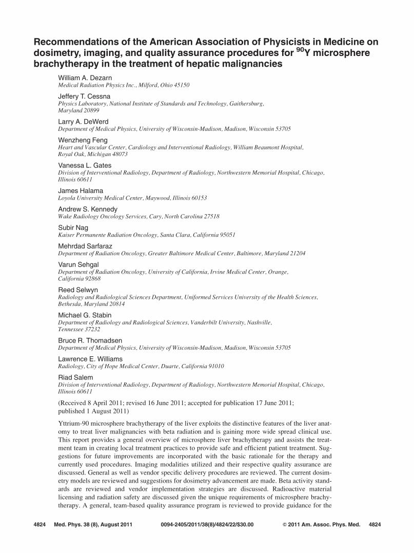
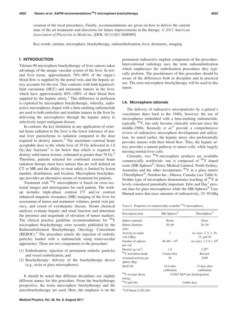
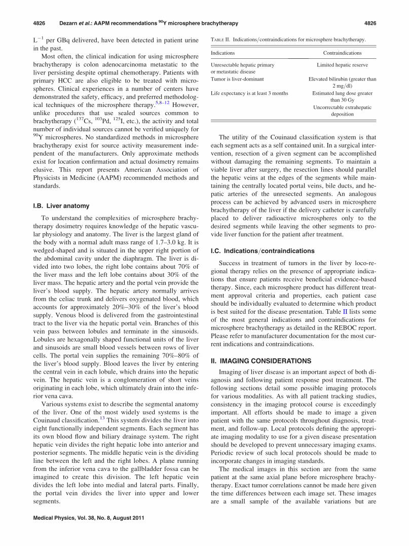
jector. Figure 1 illustrates the tumor enhancement in the an-
terior-medial liver region that occurs in the venous phase of
a three phase CT data set.
II.B. Positron emission tomography (PET)
Fluorine-18 FDG PET examinations provide physiologi-
cal data about the tumor and supplement other imaging
modalities. A PET study will identify increased metabolic
activity related to the 18F-FDG uptake. Since metabolic ac-
tivity is the intended imaging marker, patient compliance
with preimaging fasting protocols is critical.
Whole-body PET scans for liver are typically ordered 1
week before the microsphere brachytherapy procedure. The
patient fasts at least 4 h before scanning and should have
normal blood glucose levels at the time of FDG injection.
Image slices are acquired from the base of brain to the upper
thigh 1 h after IV injection of 370–555 MBq (10–15 mCi) of18F-FDG. Such a scan will typically take 20–30 min. Ideally
a PET=CT imaging scanner will be used and both the PET
and triple-phase CT imaging for treatment planning can be
completed in one session.
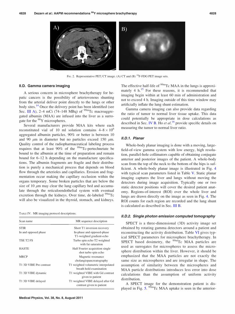
Figure 2 illustrates the PET=CT of the demonstration
patient. A slight enhancement can be seen in both images of
the anterior-medial region corresponding to the enhance-
ments noted in Fig. 1.
II.C. Magnetic resonance (MR)
MR imaging provides additional soft tissue contrast to
supplement the CT image set. Various imaging protocols,
such as the ones listed in Table VI, can aid in delineating tu-
mor volumes. Contrast studies with gadolinium (Gd) can
provide additional enhancement as needed. Given all of the
possible MR imaging protocols, it is even more important to
use a consistent imaging protocol set with MR for a particu-
lar patient. MR imaging can also be used for organ volume
measurement as mentioned in Sec. II A for CT imaging.
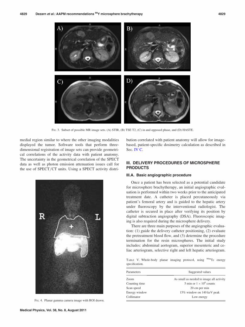
Figure 3 displays some of the MR images for the demon-
stration patient. The anterior-medial lesion that was present
on CT and PET can be seen here also. There is additional
enhancement in the right-lateral section of the liver for the
MR. Further inquiry into the time line of these images would
be necessary to determine how this MR image data will
influence the treatment plan or assessment of a patient.
TABLE III. Triple-phase CT imaging protocol.
Parameters Suggested values
Start location All phases—above diaphragm
End location All phases—though pelvic brim
Slice thickness 2.5 mm
Slice spacing 2.5 mm
Gantry angle 0�
Contrast injection rate 3–5 ml s�1
Non contrast image set Prior to any contrast studies
Arterial phase image set Use CT bolus tracking or 20–25 s delay
post contrast injection
Venous phase image set �70 s delay post contrast injection
FIG. 1. Representative three phase image set. (A) Noncontrast initial image, (B) arterial phase, and (C) venous phase. Window=level is 380=10 for the three
images.
4827 Dezarn et al.: AAPM recommendations 90Y microsphere brachytherapy 4827
Medical Physics, Vol. 38, No. 8, August 2011
II.D. Gamma camera imaging
A serious concern in microsphere brachytherapy for he-
patic cancers is the possibility of arteriovenous shunting
from the arterial deliver point directly to the lungs or other
body sites.14 Once the delivery point has been identified (see
Sec. III A), 2–4 mCi (74–148 MBq) of 99mTc macroaggre-
gated albumin (MAA) are infused into the liver as a surro-
gate for the 90Y microspheres.
Several manufacturers provide MAA kits where each
reconstituted vial of 10 ml solution contains 4–8� 106
aggregated albumin particles. 90% or better is between 10
and 90 lm in diameter but no particles exceed 150 lm.
Quality control of the radiopharmaceutical labeling process
requires that at least 90% of the 99mTc-pertechnetate be
bound to the albumin at the time of preparation and remain
bound for 6–12 h depending on the manufacture specifica-
tions. The albumin fragments are fragile and their distribu-
tion is purely a mechanical process that depends on blood
flow through the arterioles and capillaries. Erosion and frag-
mentation occur making the capillary occlusion within the
organs temporary. Some broken particles that are below the
size of 10 lm may clear the lung capillary bed and accumu-
late through the reticuloendothelial system with eventual
excretion through the kidneys. Over time, de-labeled 99mTc
will also be visualized in the thyroid, stomach, and kidneys.
The effective half-life of 99mTc MAA in the lungs is approxi-
mately 4 h.15 For these reasons, it is recommended that
imaging begin within at least 60 min of administration and
not to exceed 4 h. Imaging outside of this time window may
artificially inflate the lung shunt estimation.
Gamma camera imaging can also provide data regarding
the ratio of tumor to normal liver tissue uptake. This data
could potentially be appropriate in dose calculations as
described in Sec. IV B. Ho et al.16 provide specific details on
measuring the tumor to normal liver ratio.
II.D.1. Planar
Whole-body planar imaging is done with a moving, large-
field-of-view gamma system with low energy, high resolu-
tion, parallel-hole collimators capable of obtaining conjugate
anterior and posterior images of the patient. A whole-body
scan from the top of the neck to the bottom of the hips is suf-
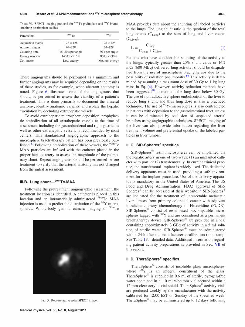
ficient. A whole-body planar image is illustrated in Fig. 4
with typical scan parameters listed in Table V. Static planar
imaging captures the liver and lungs without moving the
detectors during image acquisition. Typically one or two
static detector positions will cover the desired patient anat-
omy. Regions-of-interest (ROI) over the whole liver and
lungs are drawn directly on the image as seen in Fig. 4. The
ROI counts for each region are recorded and the lung shunt
is calculated as described in Sec. III B.
II.D.2. Single photon emission computed tomography
SPECT is a three-dimensional (3D) activity image set
obtained by rotating gamma detectors around a patient and
reconstructing the activity distribution. Table VI gives typ-
ical SPECT parameters for microsphere brachytherapy. In
SPECT based dosimetry, the 99mTc MAA particles are
used as surrogates for microspheres to assess the micro-
sphere distribution within the liver. However, it should be
emphasized that the MAA particles are not exactly the
same size as microspheres and are irregular in shape. The
assumption of similarity between the microspheres and
MAA particle distributions introduces less error into dose
calculations than the assumption of uniform activity
distribution.
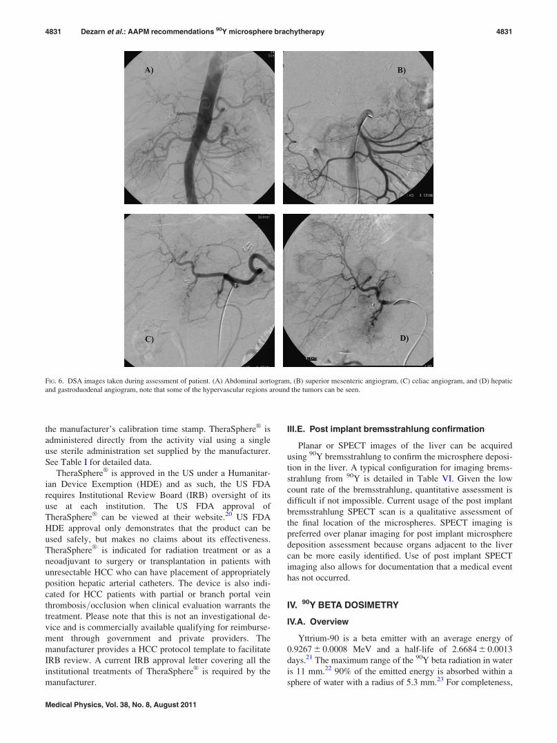
A SPECT image for the demonstration patient is dis-
played in Fig. 5. 99mTc MAA uptake is seen in the anterior-
FIG. 2. Representative PET=CT image. (A) CT and (B) 18F-FDG PET image sets.
TABLE IV. MR imaging protocol descriptions.
Scan name MR sequence description
STIR Short T1 inversion recovery
In and opposed phase In-phase and opposed-phase
T1-weighted gradient-echo
TSE T2 FS Turbo spin echo T2 weighted
with fat saturation
HASTE Half Fourier acquisition single
shot turbo spin echo
MRCP Magnetic resonance
cholangiopancreatography
T1 3D VIBE Pre contrast T1 weighted volumetric interpolated
breath hold examination
T1 3D VIBE dynamic T1 weighted VIBE with Gd contrast
given to patient
T1 3D VIBE delayed T1 weighted VIBE delayed after Gd
contrast given to patient
4828 Dezarn et al.: AAPM recommendations 90Y microsphere brachytherapy 4828
Medical Physics, Vol. 38, No. 8, August 2011
medial region similar to where the other imaging modalities
displayed the tumor. Software tools that perform three-
dimensional registration of image sets can provide geometri-
cal correlations of the activity data with patient anatomy.
The uncertainty in the geometrical correlation of the SPECT
data as well as photon emission attenuation issues call for
the use of SPECT=CT units. Using a SPECT activity distri-
bution correlated with patient anatomy will allow for image-
based, patient-specific dosimetry calculation as described in
Sec. IV C.
III. DELIVERY PROCEDURES OF MICROSPHEREPRODUCTS
III.A. Basic angiographic procedure
Once a patient has been selected as a potential candidate
for microsphere brachytherapy, an initial angiographic eval-
uation is performed within two weeks prior to the anticipated
treatment date. A catheter is placed percutaneously via
patient’s femoral artery and is guided to the hepatic artery
under fluoroscopy by the interventional radiologist. The
catheter is secured in place after verifying its position by
digital subtraction angiography (DSA). Fluoroscopic imag-
ing is also required during the microsphere delivery.
There are three main purposes of the angiographic evalua-
tion: (1) guide the delivery catheter positioning, (2) evaluate
the pretreatment blood flow, and (3) determine the procedure
termination for the resin microspheres. The initial study
includes: abdominal aortogram, superior mesenteric and ce-
liac arteriogram, selective right and left hepatic arteriogram.
FIG. 3. Subset of possible MR image sets. (A) STIR, (B) TSE T2, (C) in and opposed phase, and (D) HASTE.
FIG. 4. Planar gamma camera image with ROI drawn.
TABLE V. Whole-body planar imaging protocol, using 99mTc energy
specification.
Parameters Suggested values
Zoom As small as needed to image all activity
Counting time 5 min or 1� 106 counts
Scan speed 20 cm per min
Energy window 15% window on 140 keV peak
Collimator Low energy
4829 Dezarn et al.: AAPM recommendations 90Y microsphere brachytherapy 4829
Medical Physics, Vol. 38, No. 8, August 2011
These angiograms should be performed as a minimum and
further angiograms may be required depending on the results
of these studies, as for example, when aberrant anatomy is
noted. Figure 6 illustrates some of the angiograms that
should be performed to assess the viability of a patient’s
treatment. This is done primarily to document the visceral
anatomy, identify anatomic variants, and isolate the hepatic
circulation by occluding extrahepatic vessels.
To avoid extrahepatic microsphere deposition, prophylac-
tic embolization of all extrahepatic vessels at the time of
assessment including the gastroduodenal and right gastric, as
well as other extrahepatic vessels, is recommended by most
centers. This standardized angiographic approach to the
microsphere brachytherapy patient has been previously pub-
lished.17 Following embolization of these vessels, the 99mTc
MAA particles are infused with the catheter placed in the
proper hepatic artery to assess the magnitude of the pulmo-
nary shunt. Repeat angiograms should be performed before
treatment to verify that the arterial anatomy has not changed
from the initial assessment.
III.B. Lung shunt—99mTc-MAA
Following the pretreatment angiographic assessment, the
treatment location is identified. A catheter is placed in this
location and an intraarterially administered 99mTc MAA
injection is used to predict the distribution of the 90Y-micro-
spheres. Whole-body gamma camera imaging of 99mTc
MAA provides data about the shunting of labeled particles
to the lungs. The lung shunt ratio is the quotient of the total
lung counts (CLung) to the sum of lung and liver counts
(CLiver).
L ¼ CLung
CLung þ CLiver
(1)
Patients who have considerable shunting of the activity to
the lungs, typically greater than 20% shunt value or 16.2
mCi (600 MBq) delivered lung activity, should be disquali-
fied from the use of microsphere brachytherapy due to the
possibility of radiation pneumonitis.14 This activity is deter-
mined by assuming a maximum dose of 30 Gy to 1 kg lung
mass in Eq. (4). However, activity reduction methods have
been suggested18 to maintain the lung dose below 30 Gy.
The use of nonradioactive sphere embolization of the liver to
reduce lung shunt, and thus lung dose is also a practiced
technique. The use of 90Y-microspheres is also contradicted
in patients with deposition to the gastrointestinal tract, unless
it can be eliminated by occlusion of suspected arterial
branches using angiographic techniques. SPECT imaging of
the liver can also provide information regarding the liver
treatment volume and preferential uptake of the labeled par-
ticles in liver tumors.
III.C. SIR-SpheresVR specifics
SIR-SpheresVR
resin microspheres can be implanted via
the hepatic artery in one of two ways: (1) an implanted cath-
eter with port, or (2) transfemorally. In current clinical prac-
tice, the transfemoral implant is widely used. The dedicated
delivery apparatus must be used, providing a safe environ-
ment for the implant procedure. Use of the delivery appara-
tus is mandatory in the United States of America. The US
Food and Drug Administration (FDA) approval of SIR-
SpheresVR
can be accessed at their website.19 SIR-SpheresVR
are indicated for the treatment of unresectable metastatic
liver tumors from primary colorectal cancer with adjuvant
intrahepatic artery chemotherapy of Floxuridine (FUDR).
SIR-SpheresVR
consist of resin based biocompatible micro-
spheres tagged with 90Y and are considered as a permanent
brachytherapy device. SIR-SpheresVR
are provided in a vial
containing approximately 3 GBq of activity in a 5 ml solu-
tion of sterile water. SIR-SpheresVR
must be administered
within 24 h after the manufacturer’s calibration time stamp.
See Table I for detailed data. Additional information regard-
ing patient activity preparations is provided in Sec. VII of
this report.
III.D. TheraSphereVR specifics
TheraSphereVR
consists of insoluble glass microspheres,
where 90Y is an integral constituent of the glass.
TheraSphereVR
is supplied in 0.6 ml of sterile, pyrogen-free
water contained in a 1.0 ml v-bottom vial secured within a
12 mm clear acrylic vial shield. TheraSphereVR
activity vials
are produced weekly by the manufacturer with the activity
calibrated for 12:00 EST on Sunday of the specified week.
TheraSphereVR
may be administered up to 12 days following
TABLE VI. SPECT imaging protocol for 99mTc preimplant and 90Y brems-
strahlung postimplant studies.
Parameters 99mTc 90Y
Acquistion matrix 128� 128 128� 128
Azimuth angles 64–128 64–128
Counting time 15–30 s per angle 30 s per angle
Energy window 140 keV=15% 80 keV=30%
Collimator Low energy Medium energy
FIG. 5. Representative axial SPECT image.
4830 Dezarn et al.: AAPM recommendations 90Y microsphere brachytherapy 4830
Medical Physics, Vol. 38, No. 8, August 2011
the manufacturer’s calibration time stamp. TheraSphereVR
is
administered directly from the activity vial using a single
use sterile administration set supplied by the manufacturer.
See Table I for detailed data.
TheraSphereVR
is approved in the US under a Humanitar-
ian Device Exemption (HDE) and as such, the US FDA
requires Institutional Review Board (IRB) oversight of its
use at each institution. The US FDA approval of
TheraSphereVR
can be viewed at their website.20 US FDA
HDE approval only demonstrates that the product can be
used safely, but makes no claims about its effectiveness.
TheraSphereVR
is indicated for radiation treatment or as a
neoadjuvant to surgery or transplantation in patients with
unresectable HCC who can have placement of appropriately
position hepatic arterial catheters. The device is also indi-
cated for HCC patients with partial or branch portal vein
thrombosis=occlusion when clinical evaluation warrants the
treatment. Please note that this is not an investigational de-
vice and is commercially available qualifying for reimburse-
ment through government and private providers. The
manufacturer provides a HCC protocol template to facilitate
IRB review. A current IRB approval letter covering all the
institutional treatments of TheraSphereVR
is required by the
manufacturer.
III.E. Post implant bremsstrahlung confirmation
Planar or SPECT images of the liver can be acquired
using 90Y bremsstrahlung to confirm the microsphere deposi-
tion in the liver. A typical configuration for imaging brems-
strahlung from 90Y is detailed in Table VI. Given the low
count rate of the bremsstrahlung, quantitative assessment is
difficult if not impossible. Current usage of the post implant
bremsstrahlung SPECT scan is a qualitative assessment of
the final location of the microspheres. SPECT imaging is
preferred over planar imaging for post implant microsphere
deposition assessment because organs adjacent to the liver
can be more easily identified. Use of post implant SPECT
imaging also allows for documentation that a medical event
has not occurred.
IV. 90Y BETA DOSIMETRY
IV.A. Overview
Yttrium-90 is a beta emitter with an average energy of
0.9267 6 0.0008 MeV and a half-life of 2.6684 6 0.0013
days.21 The maximum range of the 90Y beta radiation in water
is 11 mm.22 90% of the emitted energy is absorbed within a
sphere of water with a radius of 5.3 mm.23 For completeness,
FIG. 6. DSA images taken during assessment of patient. (A) Abdominal aortogram, (B) superior mesenteric angiogram, (C) celiac angiogram, and (D) hepatic
and gastroduodenal angiogram, note that some of the hypervascular regions around the tumors can be seen.
4831 Dezarn et al.: AAPM recommendations 90Y microsphere brachytherapy 4831
Medical Physics, Vol. 38, No. 8, August 2011
it should be noted that 90Y decays over 99.98% of the time
via b� decay to the ground state of 90Zr. A small fraction of
the radionuclide (�0.01%) b� decays to the excited 0þ state
of 90Zr, which subsequently decays to the ground state via in-
ternal conversion, internal pair production (eþ e�), or two-
photon deexcitation. The miniscule internal pair production
branching ratio24 is (31.86 6 0.47)� 10�6 and might be use-
ful for the nondestructive assay of 90Y.
The average absorbed dose to the liver and tumor is cur-
rently estimated by assuming uniform uptake in these source
tissues. Measurement of the whole-tissue uptake may be
made by a variety of methods including the geometric mean
technique.25 Lung dose may be estimated using the shunting
fraction of the activity and again assuming uniform distribu-
tion in the pulmonary space. Such dose estimates are aver-
ages for whole organs and tumors.
Bremsstrahlung and beta cross-organ doses (e.g., from
tumor to liver) can be added to the above procedure if activ-
ity data can be obtained in voxel format. With conventional
gamma cameras and 99mTc MAA as the tracer, there are
several imaging methods that can provide such information,
such as the CT-assisted matrix inversion (CAMI) technique
for 2D images and SPECT imaging for 3D images.26 Given
patient-specific 3D voxel activity distributions, 90Y kernels
are available to generate the dose to adjacent voxels in both
normal tissues and tumor sites. These kernels include
bremsstrahlung effects, but do not take into account bone-
soft tissue inhomogeneities. The latter could be significant
in lung–rib interfaces and would require Monte Carlo radia-
tion transport calculations.
IV.B. Current dosimetry models
The schema developed by the Medical Internal Radiation
Dose (MIRD) Committee of the Society of Nuclear Medi-
cine is the current dosimetry standard for 90Y micro-
spheres.27 This schema assumes a uniform distribution of the
activity throughout the mass of interest. The dose rate in a
generic tissue mass, D�
, is given by
D�¼ k
A
mEh i; (2)
where k is a constant to yield the dose rate in desired units, Ais the source activity, m is the mass of tissue in which the
radiation is absorbed, and Eh i is the average energy emitted
per nuclear transition. For beta particle decay, it is also
assumed that there is no production of bremsstrahlung and
all of the decay energy is completely absorbed within the
mass. The radioactive source is permanently implanted in
the patient with no removal from the region, so the effective
half-life is simply the radioactive half-life. The absorbed
dose, calculated by integrating the dose rate over all time, is
then given by the following:
D ¼ k Eh iA0
m
ð1
0
e�lnð2Þt=T1=2 dt ¼ kA0
mEh i
T1=2
lnð2Þ : (3)
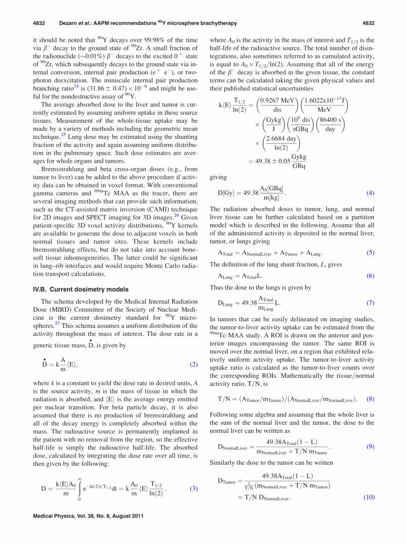
where A0 is the activity in the mass of interest and T1=2 is the
half-life of the radioactive source. The total number of disin-
tegrations, also sometimes referred to as cumulated activity,
is equal to A0� T1=2=ln(2). Assuming that all of the energy
of the b� decay is absorbed in the given tissue, the constant
terms can be calculated taking the given physical values and
their published statistical uncertainties
k Eh iT1=2
lnð2Þ ¼0:9267 MeV
dis
� �1:6022x10�13J
MeV
� �
� Gykg
J
� �109 dis
sGBq
� �86400 s
day
� �
� 2:6684 day
ln 2ð Þ
� �
¼ 49:38 6 0:05Gykg
GBq
giving
D½Gy� ¼ 49:38A0½GBq�
m½kg� : (4)
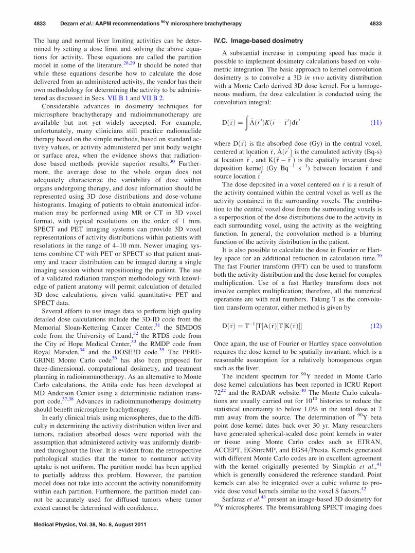
The radiation absorbed doses to tumor, lung, and normal
liver tissue can be further calculated based on a partition
model which is described in the following. Assume that all
of the administered activity is deposited in the normal liver,
tumor, or lungs giving
ATotal ¼ ANormalLiver þ ATumor þ ALung: (5)
The definition of the lung shunt fraction, L, gives
ALung ¼ ATotalL: (6)
Thus the dose to the lungs is given by
DLung ¼ 49:38ATotal
mLung
L: (7)
In tumors that can be easily delineated on imaging studies,
the tumor-to-liver activity uptake can be estimated from the99mTc-MAA study. A ROI is drawn on the anterior and pos-
terior images encompassing the tumor. The same ROI is
moved over the normal liver, on a region that exhibited rela-
tively uniform activity uptake. The tumor-to-liver activity
uptake ratio is calculated as the tumor-to-liver counts over
the corresponding ROIs. Mathematically the tissue=normal
activity ratio, T=N, is
T=N ¼ ATumor=mTumorð Þ= ANormalLiver=mNormalLiverð Þ: (8)
Following some algebra and assuming that the whole liver is
the sum of the normal liver and the tumor, the dose to the
normal liver can be written as
DNormalLiver ¼49:38ATotal 1� Lð Þ
mNormalLiver þ T=N mTumor
: (9)
Similarly the dose to the tumor can be written
DTumor ¼49:38ATotal 1� Lð Þ
1T=N
mNormalLiver þ T=N mTumorð Þ¼ T=N DNormalLiver: (10)
4832 Dezarn et al.: AAPM recommendations 90Y microsphere brachytherapy 4832
Medical Physics, Vol. 38, No. 8, August 2011
The lung and normal liver limiting activities can be deter-
mined by setting a dose limit and solving the above equa-
tions for activity. These equations are called the partition
model in some of the literature.28,29 It should be noted that
while these equations describe how to calculate the dose
delivered from an administered activity, the vendor has their
own methodology for determining the activity to be adminis-
tered as discussed in Secs. VII B 1 and VII B 2.
Considerable advances in dosimetry techniques for
microsphere brachytherapy and radioimmunotherapy are
available but not yet widely accepted. For example,
unfortunately, many clinicians still practice radionuclide
therapy based on the simple methods, based on standard ac-
tivity values, or activity administered per unit body weight
or surface area, when the evidence shows that radiation-
dose based methods provide superior results.30 Further-
more, the average dose to the whole organ does not
adequately characterize the variability of dose within
organs undergoing therapy, and dose information should be
represented using 3D dose distributions and dose-volume
histograms. Imaging of patients to obtain anatomical infor-
mation may be performed using MR or CT in 3D voxel
format, with typical resolutions on the order of 1 mm.
SPECT and PET imaging systems can provide 3D voxel
representations of activity distributions within patients with
resolutions in the range of 4–10 mm. Newer imaging sys-
tems combine CT with PET or SPECT so that patient anat-
omy and tracer distribution can be imaged during a single
imaging session without repositioning the patient. The use
of a validated radiation transport methodology with knowl-
edge of patient anatomy will permit calculation of detailed
3D dose calculations, given valid quantitative PET and
SPECT data.
Several efforts to use image data to perform high quality
detailed dose calculations include the 3D-ID code from the
Memorial Sloan-Kettering Cancer Center,31 the SIMDOS
code from the University of Lund,32 the RTDS code from
the City of Hope Medical Center,33 the RMDP code from
Royal Marsden,34 and the DOSE3D code.35 The PERE-
GRINE Monte Carlo code36 has also been proposed for
three-dimensional, computational dosimetry, and treatment
planning in radioimmunotherapy. As an alternative to Monte
Carlo calculations, the Attila code has been developed at
MD Anderson Center using a deterministic radiation trans-
port code.37,38 Advances in radioimmunotherapy dosimetry
should benefit microsphere brachytherapy.
In early clinical trials using microspheres, due to the diffi-
culty in determining the activity distribution within liver and
tumors, radiation absorbed doses were reported with the
assumption that administered activity was uniformly distrib-
uted throughout the liver. It is evident from the retrospective
pathological studies that the tumor to nontumor activity
uptake is not uniform. The partition model has been applied
to partially address this problem. However, the partition
model does not take into account the activity nonuniformity
within each partition. Furthermore, the partition model can-
not be accurately used for diffused tumors where tumor
extent cannot be determined with confidence.
IV.C. Image-based dosimetry
A substantial increase in computing speed has made it
possible to implement dosimetry calculations based on volu-
metric integration. The basic approach to kernel convolution
dosimetry is to convolve a 3D in vivo activity distribution
with a Monte Carlo derived 3D dose kernel. For a homoge-
neous medium, the dose calculation is conducted using the
convolution integral:
Dðr*Þ ¼ð
~Aðr*0ÞKðr*� r*0Þdr
*0 (11)
where Dðr*Þ is the absorbed dose (Gy) in the central voxel,
centered at location r*, ~Aðr*0Þ is the cumulated activity (Bq-s)
at location r*0
, and Kðr*� r*0Þ is the spatially invariant dose
deposition kernel (Gy Bq�1 s�1) between location r*
and
source location r*0
.
The dose deposited in a voxel centered on r*
is a result of
the activity contained within the central voxel as well as the
activity contained in the surrounding voxels. The contribu-
tion to the central voxel dose from the surrounding voxels is
a superposition of the dose distributions due to the activity in
each surrounding voxel, using the activity as the weighting
function. In general, the convolution method is a blurring
function of the activity distribution in the patient.
It is also possible to calculate the dose in Fourier or Hart-
ley space for an additional reduction in calculation time.39
The fast Fourier transform (FFT) can be used to transform
both the activity distribution and the dose kernel for complex
multiplication. Use of a fast Hartley transform does not
involve complex multiplication; therefore, all the numerical
operations are with real numbers. Taking T as the convolu-
tion transform operator, either method is given by
Dðr*Þ ¼ T�1½T½Aðr*Þ�T½Kðr*Þ�� (12)
Once again, the use of Fourier or Hartley space convolution
requires the dose kernel to be spatially invariant, which is a
reasonable assumption for a relatively homogenous organ
such as the liver.
The incident spectrum for 90Y needed in Monte Carlo
dose kernel calculations has been reported in ICRU Report
7222 and the RADAR website.40 The Monte Carlo calcula-
tions are usually carried out for 1010 histories to reduce the
statistical uncertainty to below 1.0% in the total dose at 2
mm away from the source. The determination of 90Y beta
point dose kernel dates back over 30 yr. Many researchers
have generated spherical-scaled dose point kernels in water
or tissue using Monte Carlo codes such as ETRAN,
ACCEPT, EGSnrcMP, and EGS4=Presta. Kernels generated
with different Monte Carlo codes are in excellent agreement
with the kernel originally presented by Simpkin et al.,41
which is generally considered the reference standard. Point
kernels can also be integrated over a cubic volume to pro-
vide dose voxel kernels similar to the voxel S factors.42
Sarfaraz et al.43 present an image-based 3D dosimetry for90Y microspheres. The bremsstrahlung SPECT imaging does
4833 Dezarn et al.: AAPM recommendations 90Y microsphere brachytherapy 4833
Medical Physics, Vol. 38, No. 8, August 2011
not have adequate resolution for dose distribution calcula-
tion. Therefore an MAA-SPECT image, which could be
obtained at the same time of lung shunt study, is used for
dose calculation. The MAA-SPECT counts per voxels are ar-
bitrary values that depend on many factors including acquisi-
tion time and reconstruction algorithm. In addition, there
would be some background counts introduced by the recon-
struction algorithm in spite of the fact that microspheres are
exclusively administered and retained in the liver (except for
a few percent lung shunt). Hence, the relative SPECT counts
in each voxel of the image is converted to absolute activity
by normalizing the total counts minus background to the
total 90Y administered activity. The radiation absorbed dose
distribution is calculated by convolving the activity distribu-
tion obtained from the SPECT images with a dose kernel for90Y. Isodose lines can be derived from the 3D dose distribu-
tion and displayed on the corresponding CT scans registered
to the SPECT scans. The dose-volume histogram of the tu-
mor, liver, and other organs can be derived from the calcu-
lated dose distribution and the volumes transferred from the
CT scan. Research into more sophisticated methods to cor-
rect SPECT counts to activity is being conducted and is
called quantitative SPECT or QSPECT.32,44,45 It should be
noted that these research systems are not in widespread use
at this time and no commercial system exists for microsphere
brachytherapy dosimetry.
One caveat must be introduced in a voxel-based strategy.
Traditionally, it has been assumed that there is essentially no
movement of radioactivity in source tissues. There has been
little attempt to measure the kinetics of 99mTc MAA away
from deposition sites due to the degradation of the MAA par-
ticles over time. Moreover, the 6 h half-life of 99mTc may
not be useful for long-term follow-up that is relevant to the
64 h half-life of 90Y. If kinetics measurements are possible,
the obvious question is the following of individual voxels in
the tissues. SPECT=CT and PET=CT scanners could prove
useful in this application.
V. MICROSPHERE ACTIVITY MEASUREMENTSTANDARDS
V.A. 90Y calibration—international standards
Physical measurement standards for the determination of
radioactivity are typically held by a country’s National Me-
trology Institute (NMI). For the United States, the NMI is
the National Institute of Standards and Technology (NIST).
This standard is most often in the form of a primary mea-
surement method, i.e., a method that relies on first principals
instead of a calibration factor for an instrument. Due to the
high efficiency of the method, approximately 98% for 90Y,
liquid-scintillation (LS) counting is routinely used for activ-
ity measurements of beta-emitting radionuclides in solution.
Two different methods may be used to determine the effi-
ciency: the CIEMAT=NIST (Centro de Investigaciones
Energeticas, Medioambientales y Technologicas) efficiency
tracing method46,47 or the Triple-to-Double Coincidence Ra-
tio method.48 Both of these methods are used at NIST.
Although this method is straight forward, care must be taken
to ensure that liquid-scintillation cocktails remain stable
over the duration of counting. Typically, expanded uncer-
tainties (k¼ 2 or two standard deviations) of less than 1%
can be achieved. NIST disseminates the activity standard for90Y through the yearly production of Standard Reference
Materials and through the availability of calibration services.
Comparisons between NMIs are overseen by the Interna-
tional Committee for Weights and Measures (CIPM). For
signatories of the Mutual Recognition Arrangement (MRA),
these results are tabulated in the Key Comparison Database.
The most recent comparison of 90Y was published in 2005.49
Eight laboratories measured the activity of aliquots of solu-
tion distributed by NIST. The standard deviation of the mean
of the reported results was 0.05%, well below the individual
stated uncertainties, indicating consistency in the Y-90 inter-
national standard.
V.B. SIR-SpheresVR activity standard
SIR-SpheresVR
do not have a NIST traceable calibration at
the publication of this report; however, activity measure-
ments of 90Y SIR-SpheresVR
have been performed at The
Australian Nuclear Science and Technology Organization
(ANSTO) and the Australian Radiopharmaceuticals and
Industrials (ARI). ANSTO is the Australian designated labo-
ratory for radioactivity measurements. The clinical data used
to support the FDA application was based on an ion chamber
calibration that is still in use for the production and release
of the products. Each vial of microspheres is calibrated indi-
vidually within a 610% range. When new customers start
use, the manufacturer provides an activity from the batch
report for the first three microsphere vials shipped. This
allows the customer to normalize their ion chamber to the
same calibration as the manufacturer. Further calibration val-
ues can be requested as needed by the user.
It is also noteworthy that activity measurements made
using dose calibrators will vary as the distribution of 90Y
varies within the dose calibrator and the sample container.
For example, an activity measurement made on a sample of
settled, 90Y labeled, SIR-SpheresVR
microspheres will vary
considerably from the activity measured using the same
quantity of 90Y in an yttrium-chloride solution where the ac-
tivity is homogeneously distributed throughout the sample
container. Similarly, there are geometry dependent varia-
tions in activity measurements when different shaped sample
containers are used. For this reason, Sirtex recommends to
its customers that all activity measurements be made on ma-
terial in the shipping vial, not the V bottomed v-vial used for
patient delivery.
Mo et al.50 detailed another calibration of the activity of
SIR-SpheresVR
independent of the manufacturer and it is
briefly described. For the production of SIR-SpheresVR
, it was
necessary to relate measurements made during production to
Australian national standards for measurement of 90Y. Cali-
bration factors were determined for four different ionization
chamber models using an intermediate geometry of the pro-
duction and the final geometry. Ionization chamber measure-
ments were made on samples of SIR-SpheresVR
using the
4834 Dezarn et al.: AAPM recommendations 90Y microsphere brachytherapy 4834
Medical Physics, Vol. 38, No. 8, August 2011
ionization chambers at ARI. Following these measurements,
the microspheres were chemically digested to yield a solu-
tion containing only liquid. During the sample digestion,
care was taken to account for losses from solution by collec-
tion and measurement of the vapors from the reaction. The
resulting solution was measured on the ANSTO secondary
standard ionization chamber.
While this work established a procedure for activity mea-
surement and quality control of the SIR-SpheresVR
product,
the ionization chamber models used are not routinely used or
available in the US. Therefore, the calibration factors deter-
mined are not generally useful for US clinical measurements.
Also of concern is the fact that the link from measurements
at ARI to US national radioactivity measurement standards
is based on an ionization chamber measurement of a pure so-
lution of the beta emitter. This measurement has an inher-
ently higher uncertainty than direct liquid-scintillation
measurements. The main uncertainty in SIR-SpheresVR
comes
from the volume and homogeneity of the sample. A change
in the volume of SIR-SpheresVR
can affect the activity meas-
urements due to geometry differences. Similarly, the homo-
geneity of the sample can affect the activity measurements
of the sample. Part of SIR-SpheresVR
training requires the
technician to resuspend the SIR-SpheresVR
prior to measuring
the activity. An additional problem comes from the lack of
uniformity on the shipping vials. The variations in the thick-
ness of the glass in parts of the vials lead to variations in the
penetration of the betas through the glass and into the wall
of the chamber.
An independent, nondestructive spectroscopic analysis of
SIR-SpheresVR
at the University of Wisconsin has measured
an activity 26% higher than the manufacturer indicated
activity.51 Section V E gives more details on this
measurement.
V.C. TheraSphereVR activity standard
Nordion participates in the NIST Radioactivity Measure-
ment Assurance Program (NRMAP). Dial settings have been
determined for the measurement of TheraSphereVR
by NIST
in commercially available Capintec dose calibrators.52 NIST
maintains a secondary measurement standard for routine cal-
ibration of TheraSphereVR
. Nordion routinely verifies its dose
calibrator measurements with NIST, for the full range of
available dose sizes.
TheraSphereVR
user sites are supplied with TheraSphereVR
dose vial information on vials initially shipped. The meas-
ured activity value of the dose vial, referenced to the speci-
fied calibration date and time, is provided to the user site.
This allows for site specific determination of dose calibrator
settings and geometry factors to establish equivalency with
Nordion measurements. The site specific factors determined
can then be applied to subsequent TheraSphereVR
activity
vials received.
TheraSphereVR
is supplied with the dose vial contained
in a nonremovable acrylic shield. The acrylic shield is an
integral part of the safety shielding for the product. User
sites will need to use a dose calibrator “dip stick” that
will hold the TheraSphereVR
dose vial in its acrylic shield
in a repeatable, fixed position. The highest accuracy of
dose calibrator measurements is achieved if all of the
microspheres are located at the bottom tip of the dose v-
vial. Prior to dose calibrator measurement, it is recom-
mended to gently rock and tap the acrylic shield to ensure
that the microspheres are located at the bottom of the v-
vial. The dose vial should always be measured and main-
tained upright at all times.
V.D. Vendor to local clinic
Determining the 90Y reference activity for the local clinic
is an integral part of the microsphere brachytherapy pro-
gram. Both vendors will supply reference activity samples to
users upon request to establish a local standard. Typically,
dose calibrators in the nuclear medicine department are used
at a given clinic to verify activity values. Variations in con-
tainer materials and source position within the dose calibra-
tor can affect the local calibration standard.50,53,54 In the
absence of a well defined local calibration procedure, varia-
tions in activity measurements on the order of 10% can
occur.55,56 Given no availability of an Accredited Dosimetry
Calibration Laboratory (ADCL) traceable activity standard
for microspheres, a fixed geometrical technique for reference
activity measurements should be established at the local
clinic level and used consistently.
For example, the same container and the same position
within the dose calibrator should be used consistently. Using
a vendor supplied reference activity vial, dose calibrator set-
tings can be determined by the following simple procedure:
(1) vary the dose calibrator calibration value and record the
measured activity and (2) graph the measured activity di-
vided by the vendor calibration as a function of calibrator
setting. The point that the quotient reaches one is the dose
calibrator calibration value to use for the local clinic.
In order to determine the postprocedure residual activity,
both microsphere products discuss a method using a survey
meter at four compass points around a container holding the
items to be measured. Preimplant, an initial reading is taken
with only the delivery vial placed in the container. The sur-
vey meter response for this measurement is equated with the
calibrated activity being delivered to the patient. Following
the procedure, the delivery vial and the delivery tubing are
placed in the container and measured with the same survey
meter. The ratio of the final reading to the initial reading is
taken as the fraction of the activity not delivered and sub-
tracted from the patient’s activity in the final dosimetry. The
accuracy and precision of this method have not been eval-
uated. Dezarn and Kennedy56 completed a study to show
that measuring post implant residual activity in a dose cali-
brator is similar to the four compass point method. All the
residual activity from a series of microsphere brachytherapy
procedures was measured by both methods and found to
give consistent results. Given the possible inconsistencies
using a survey meter for activity measurements, it is recom-
mended to use a dose calibrator for post implant activity
determination.
4835 Dezarn et al.: AAPM recommendations 90Y microsphere brachytherapy 4835
Medical Physics, Vol. 38, No. 8, August 2011
V.E. New calibration methods for 90Y
Widely used nondestructive assays of 90Y use reentrant
ionization chambers or dose calibrators to detect bremsstrah-
lung or beta radiation directly. The bremsstrahlung produc-
tion is highly dependent on the source material, its container,
and the calibrator chamber wall. The ionization current also
depends on the probability of electron detection within the
chamber, which varies with electron energy and individual
dose calibrator construction. Slight variations in the con-
tainer wall thickness, solution volume, or location within the
well can lead to an increase in the overall assay uncertainty
when using the manufacturer supplied calibration factor,
which is typically traceable to national standards. Siegel etal.53 and Zimmerman et al.54 determined volumetric correc-
tions and calibration factors for several commercially avail-
able dose calibrators for solutions of 90Y (ZevalinVR
) in a 10
ml syringe. The volume dependence varied from 0.84 to
5.20% over a volume range of 6 ml and the average dial set-
ting varied from 0.89 to 3.60%.
Based on current measurements of microsphere activity,
the uncertainties and estimates of geometrical uncertainty in
dose delivered can be combined to yield a total dose delivery
uncertainty on the order of 20%. One of the largest compo-
nents of this total is the activity measurement. Thus, an
improvement in the calibration methods and the measure-
ment of standards for microspheres would help to greatly
reduce the dose uncertainty. New calibration methods may
involve branching ratios and even measurements of particu-
late radiation.
A nondestructive spectroscopic assay51 can be employed
due to a newly updated low uncertainty positron branching
ratio of 90Y. The assay is based on the detection of the 511
keV annihilation radiation produced from the positron decay
of 90Y. The assay provides precise and relatively geometry
independent calibration factors that can be transferred to
clinical ionization chambers. Positron emitting impurities
such as 88Y should be taken into account by monitoring
other photon emissions such as 898 and 1836 keV. Recently,
this method was utilized to assay a 3 GBq sample of
SIR-SpheresVR
provided by the manufacturer. The measured
activity was (3.81 6 1.8%) GBq, 26% greater than the manu-
facturer calibrated activity.
The prescribed activity for SIR-SpheresVR
is based upon
clinical results and 90Y activities obtained by the manufac-
turer during clinical trials. The manufacturer stated activ-
ity should continue to be used until new activity standards
and dosimetric implications are studied. End users should
continue to use the manufacturer activity standard until
NIST or an ADCL can independently provide calibration
factors.
VI. RADIOACTIVE MATERIAL LICENSING ANDRADIATION SAFETY
VI.A. US NRC and agreement state regulations
The US Nuclear Regulatory Commission (NRC) regulates90Y microspheres as medical devices since the microspheres
do not interact pharmacologically, physiologically, or
biochemically within the body. In other words, 90Y micro-
spheres are not metabolized and hence are not radiopharma-
ceuticals such as 131I Lipiodol, for example. This regulation
is codified in 10 CFR 35.1000 “Other Medical Uses of
Byproduct Material or Radiation from Byproduct Material.”
NRC licensing guidance specific to 90Y microspheres can be
found at their website.57 The licensee shall follow all the
requirements in 10 CFR Part 35 for brachytherapy sources
and manual brachytherapy except where the licensing com-
mitments of 10 CFR 35.1000 provide regulatory relief. NRC
agreement states must enforce at least the NRC regulations
but may also impose further regulations. When starting a
microsphere brachytherapy program in an agreement state,
the licensee should contact the local regulatory agency for
further possible requirements.
VI.B. Authorized user and authorized medicalphysicist
A physician must satisfy the training requirements of 10
CFR 35.390 or 10 CFR 35.490 to become an authorized
user (AU) of 90Y microspheres. The basic requirements are
physicians who have completed residency training pro-
grams in radiation therapy or nuclear medicine and are cer-
tified by a medical specialty board recognized by the NRC.
Interventional radiologists may also apply for AU status for90Y microspheres by following the procedures in the NRC90Y microsphere guidance.57 Medical and health physicists
are ineligible to be an AU. Authorized medical physicist
(AMP) status is not currently defined for 90Y microspheres.
Training requirements of 10 CFR 35 to become an AMP for
other procedures can be used as a model to create local
departmental physicist training standards for 90Y micro-
spheres. In addition to the requirements of 10 CFR 35, the
individual should complete training in the operation of the
specific microsphere delivery system and become knowl-
edgeable of safety procedures and clinical use of each type
of microsphere. The physician should complete vendor
specific training and perform three cases supervised by a
vendor trainer or another AU for each type of microsphere
for which the physician is seeking AU status.
VI.C. Sealed source inventory and labelingrequirements
Leak tests are not required because the activity per micro-
sphere (the sealed source) meets the criteria in 10 CFR
35.67(f); thereby relieving the licensee from the require-
ments of performing such tests. However, semiannual physi-
cal inventory of microspheres aggregates (e.g., vials) is still
required by most regulatory agencies. The NRC guidance
states that the inventory should include the following
information:
1. radionuclide and physical form;
2. unique identification of each vial in which the micro-
spheres are contained;
3. total activity contained in each of the vial(s); and
4836 Dezarn et al.: AAPM recommendations 90Y microsphere brachytherapy 4836
Medical Physics, Vol. 38, No. 8, August 2011

4. location(s) of the vial(s).
The following additional guidance applies when the radi-
oactive microspheres are placed in vials, syringes, or radia-
tion shields that are not labeled by the manufacturer:
1. Label vials and vial radiation shields with radionuclide
and form (e.g., 90Y resin or glass microspheres).
2. Label syringes and syringe radiation shields with the radi-
onuclide, form, and therapeutic procedure (e.g., 90Y resin
or glass microspheres, brachytherapy).
VI.D. Written directive
For the purpose of written directives and medical event
reporting requirements in the NRC 90Y microsphere guid-
ance,57 “prescribed dose” means the total dose (rad or Gy).
Alternatively, prescribed activity (mCi or GBq) may be used
in lieu of prescribed dose. The written directive shall
include:
1. patient or human research subject’s name;
2. treatment date;
3. signature of the AU for 90Y microspheres;
4. treatment site;
5. radionuclide (including the physical form [90Y
microspheres]);
6. prescribed dose or prescribed activity;
7. maximum dose(s)=activity(ies) that would be acceptable
to the specified site(s) outside the primary treatment site
due to shunting (e.g., lung and gastrointestinal tract)
8. manufacturer;
9. and, if appropriate for the type of microsphere used, the
statement “or dose=activity delivered at stasis.”
The licensee shall record the administered dose=activity
delivered to the primary treatment site and to the other speci-
fied site(s). If the administration was terminated because of
stasis, then the total dose=activity to the treatment site is the
value of the total dose=activity administered when stasis
occurred and the administration was terminated. The record
should be prepared within 24 h after the completion or termi-
nation of the administration and must include the name of
the individual who made the assessment, the date, and the
signature of an AU for 90Y microspheres, if terminated due
to stasis.
Stasis in the context of microsphere brachytherapy means
that blood flow through a given region has been stopped.
VI.E. Medical event
A medical event is defined in 10 CFR 35.3045 “Report
and notification of a medical event.” The elements of this
regulation that apply to microsphere brachytherapy are par-
aphrased here. The actual documentation required will
depend on the licensee’s Radioactive Material License.
Administration of 90Y microspheres must be performed in
accordance with the written directive. If stasis is docu-
mented as a treatment endpoint in the written directive and
reached in a treatment, a medical event has not occurred.
Treatment procedures should describe how the total dose to
the treatment site, as well as, potential dose to other sites,
will be determined before and upon completion of the
administration, to confirm that the administration is per-
formed in accordance with the written directive. Moreover,
procedures should describe how events that are not the
results from intervention of a patient or research subject
are reported to regulatory agencies. The reporting require-
ments of the NRC are described in 10 CFR 35.3045(b)–(g).
A 90Y microspheres medical event is defined as the
following:
1. the administration of byproduct material results in a dose
that exceeds 0.05 Sv (5 rem) effective dose equivalent or
0.5 Sv (50 rem) to an organ or tissue from the use of the
wrong radionuclide; or
2. the administration of 90Y-microspheres results in a dose:
a) that differs from the prescribed dose or the dose that
would have resulted from the prescribed activity, as
documented in the written directive, by more than
0.05 Sv (5 rem) effective dose equivalent or 0.5 Sv
(50 rem) to an organ or tissue, and the total dose-
activity administered differs from the prescribed dos-
e=activity, as documented in the written directive, by
20% or more; or
b) that exceeds 0.05 Sv (5 rem) effective dose equiva-
lent or 0.5 Sv (50 rem) to an organ or tissue from an
administration to the wrong individual or human
research subject, via the wrong route, or by the
wrong mode of treatment; or
c) to an organ or tissue other than the treatment site that
exceeds by 0.5 Sv (50 rem) to an organ or tissue and
by 50% or more of the prescribed dose=activity
expected to that site from the administration of 90Y
microspheres, if carried out as specified in the pread-
ministration portion of the written directive.
VI.F. Instrumentation
The radiation detector used to monitor for contamination
must be sensitive to the radiation likely to be encountered.
Hand-held survey meters using ionization chambers or Gei-
ger–Muller (GM) tubes that are sensitive to gamma and beta
radiation should be used in microsphere brachytherapy pro-
cedures. With TheraSphereVR
, a single microsphere carries
approximately 2500 Bq (67 nCi) of 90Y at the calibration
time. Most regulations consider the presence of 185 Bq (5
nCi) indicative of contamination. Thus, even a single errant
sphere constitutes external contamination. For SIR-
SpheresVR
, at approximately 50 Bq (1.35 nCi) per sphere at
the calibration time, four spheres just exceeds the regulatory
limit. Thus, very small amounts of material leaking from the
delivery system produce sizable contamination. Normally,
for this level of contamination, wipe tests would be per-
formed. However, the counting equipment and time would
not be available in the interventional radiology room imme-
diately following the procedure, and hand-held survey
instruments are used.
4837 Dezarn et al.: AAPM recommendations 90Y microsphere brachytherapy 4837
Medical Physics, Vol. 38, No. 8, August 2011
VI.G. Procedure room and staff surveys
All personnel participating in the procedure must wear
protective equipment including lead apron, scrubs, gloves,
gown, face mask, and shoe covers. They also must wear
whole-body dosimeters while those with the likelihood of
having their hands near the source should also wear extrem-
ity dosimeters. The floor of the angiography room should be
covered with large water absorbing drapes before the treat-
ment to confine any contamination. Everyone leaving the
room during the procedure is scanned for contamination and
all contaminated items are collected and disposed of as radi-
ation waste. Following the microsphere brachytherapy pro-
cedure, a radiation survey assures that no radioactivity has
contaminated the room, waste, or personnel.
The survey procedure follows the same pattern as that
would be performed following a radioactive solution treat-
ment. Each person in the room is monitored, surveying their
hands (tops and bottoms), their anterior and posterior surfa-
ces and the bottoms of their feet. No one leaves the room
before being monitored. All the equipment and surfaces are
surveyed, paying particular attention to anything wet or
bloody. The surfaces include the floor, which should have
been covered. During the survey, either of the personnel or
of the materials, the presence of the patient may produce a
background reading high enough to mask potential contami-
nation. Both moving away from the patient as much as possi-
ble and keeping the surveyor (assumedly still wearing a lead
apron) between the patient and the person or material to be
surveyed helps reduce the background, usually to levels
compatible with detecting contamination.
The background radiation from the patient can be difficult
to shield especially around the floor area close to the patient.
In such cases, the floor covering can be taken up and the pads
measured away from the patient. During the removal, the
pads are considered contaminated, so that the tape around the
edges holding the pads in place must be removed very care-
fully and the pads rolled inward from the edges, to contain
potential contamination. Likewise, sheets and towels on the
patient likely need to be surveyed away from the patient.
Even though, the survey procedures for 90Y microspheres
are similar to radioactive solution treatments, the remedial
actions for spills or contamination are different. The first
response for a radioactive solution spill is to cover the spill
with coarse absorbent material such as surgical towels and
then to use a plastic-backed, absorbent pad, which would
absorb the solution, and presumably the radioactive material
with it. With a microsphere spill, the towels can absorb the
liquid and trap the microspheres. A contaminated surface
usually implies the presence of microspheres. Because
microspheres can become trapped in a crevice, such features
are particularly challenging. Decontamination sprays and
solutions rarely help but on the other hand, foaming products
have some chance of lifting the spheres where they could be
retrieved. Adhesive tape can also be used to capture micro-
spheres. Cleaning attempts should be repeated until back-
ground radioactivity levels are reached. If removal is not
possible then the spill should be dried, covered with approxi-
mately 1 cm of low Z material, sealed or waterproofed (e.g.,
with a plastic film), surveyed, and labeled.
VI.H. Radiation safety considerations in patientsundergoing transplantation or surgical resection
There will be instances where a patient undergoing 90Y
microspheres therapy becomes a surgical candidate for
resection or liver transplantation. Although investigators
should follow their own institutional guidelines for elapsed
time from 90Y treatment to time of surgery or transplanta-
tion, this should be balanced against the medical needs of
the patient. Monitoring the patient surface dose rate is a typi-
cal method to determine what precautions should be fol-
lowed at the time of surgery. Generally, if the patient’s skin
surface dose rate that is less than 20 lSv=h, special handling
by the surgeon is not required at the time of the procedure.58
That is, lead gloves, special instruments, and extremity radi-
ation monitors (e.g., ring badge) are not necessary. Radiation
safety should be notified for transportation and storage of the
explanted specimen. Institutional experience may vary but
patients treated with 90Y microspheres typically have surface
dose rates less than 20 lSv=h at 30 days regardless of admin-
istered activity.
Following surgery (resection or transplantation), the
explanted liver should be placed in a formaldehyde solution
for storage in a leak proof container. The container should
be refrigerated while in storage. Because the explanted liver
may contain radioactive microspheres, the container should
be monitored with an energy compensated Geiger–Mueller
detector or a portable ionization chamber. If the dose rate at
the surface of the container exceeds 50 lSv=h, the container
should be placed behind lead shielding for decay-in-storage.
While in storage, the explanted liver container should be la-
beled as radioactive material per local radiation safety guide-
lines. Institutions should also follow federal and state
guidelines for room posting of areas containing radioactive
material or designated radiation areas. Once the container
has decayed for 60 days, the surface exposure rate will usu-
ally be less than 5–10 lSv=h using a portable ionization
chamber. At that time, the pathologist may handle the speci-
men in the grossing lab using their standard, universal pre-
cautions, and techniques. If immediate determination of
clear surgical margins is required, the volume of tissue
handled in analyzing a frozen section is minimal and should
not pose a radiation risk to the staff. Hand radiation monitors
can be worn to monitor the staff exposure. Once any patho-
logic analysis is complete, all tissues should be placed in the
original storage container and returned to radioactive mate-
rial storage. All areas where the liver specimen was handled
should be surveyed with a radiation detection instrument
such as a GM thin window detector. Readings should be less
than 1 lSv=h.
VI.I. Radiation safety considerations in case ofautopsy, burial or cremation
National Council for Radiation Protection and Measure-
ments (NCRP) Report No. 155 “Management of Radionuclide
4838 Dezarn et al.: AAPM recommendations 90Y microsphere brachytherapy 4838
Medical Physics, Vol. 38, No. 8, August 2011
Therapy Patients (2006),” provides guidance regarding burial
of patients with permanent implants on levels of radioactivity
below which no precautions are needed. NCRP Report
No.161, “Management of Persons Contaminated with Radio-
nuclides: Handbook (NCRP 2010),” also gives practical guid-
ance to medical and mortuary personnel, although more in the
context of dealing with generally contaminated subjects.
NCRP reports are generally accepted as appropriate guidance
for use in the absence of regulatory requirements. Interna-
tional Commission on Radiological Protection Publication 94
“Release of Patients after Therapy with Unsealed Radionu-
clides (2005),” provides international guidance on burial, cre-
mation, or the autopsy of patients who have received
therapeutic radionuclides.
If an autopsy must be performed on the corpse, special
precautions may be required if the activity exceeds the limits
set for cremation. However, microsphere brachytherapy with90Y microspheres usually only involves significant quantities
in the liver. Therefore, an autopsy could be performed with-
out the pathologist exceeding the limits for radiation expo-
sures to the general public if the liver can be excised and set
aside for radioactive decay. If an autopsy is performed
within 34 days of treatment, the physician may want to take
the conservative approach and remove the liver or treated tis-
sue prior to performing the autopsy to reduce any extensive
exposure (less than 1 h).
For postmortem patients, there would be no radiation
safety restrictions on embalming or burial since, it is
extremely unlikely that embalmers and funeral workers
would receive radiation doses in excess of the public dose
limit of 1 mSv per year. In the United States of America, a
crematorium may accept a corpse if the radioactivity is less
than 74 MBq for all radionuclides (ICRP94). Individual
state regulations may prevent cremation based on contami-
nates introduced during the manufacturing process. For a
typical patient that was administered 1.5 GBq of 90Y micro-
spheres, the corpse may have to be stored if death occurred
within 12 days of the microsphere brachytherapy treatment.
This is a minor consideration that should be decided on a
case-by-case basis. As stated above, the conservative
approach would be to remove the liver and store it for radi-
oactive decay.
VI.J. Radioactive material storage
At the end of a procedure, there will be at least residual
amounts of 90Y microspheres present in transfer tubing, vari-
ous containers, and various drapes. A physicist should sur-
vey everything in the procedure room with an appropriate
survey meter. Any contaminated materials should be placed
in beta shielded containers and placed in waste storage. The
licensee has to hold the radioactive material until the con-
tainer surface radioactivity cannot be distinguished from
background with the radiation survey meter set on its most
sensitive scale and no shielding being used. When the radio-
active material has reached background levels the licensee
will remove or obliterate all radiation labels. Records of all
disposals will be kept for 3 yr. The disposal record will
include the disposal date, the storage entry date, the radionu-
clide disposed, the survey instrument used, the background
rate used, and the dose rate measured at the surface of each
container.
Yttrium-90 can be produced by neutron bombardment of89Y in a nuclear reactor. In this production modality there
are also (2n,c) and (n,2n) reactions occurring that produce91Y and 88Y, respectively. Depending on the construction of
the microsphere, other by-product radionuclides can be gen-
erated in reactor production. Long-lived radioactive by-prod-
ucts may not be a problem for microspheres manufactured
using carrier free 90Y from a 90Sr generator. While 10 CFR
35.92 allows licensees to store radioactive material with a
physical half-life of less than 120 days for decay-in-storage
before disposal in ordinary trash, in March 2007, the US
NRC issued “NRC Information Notice 2007-10: Yttrium-90
TheraSphereVR
and SIR-SphereVR
Impurities.” The purpose of
this notice was to notify users that samples of radioactive
microspheres were radioactive longer than expected because
of 88Y and other long-lived by-products. None of the by-
products were at levels high enough to influence the radia-
tion dosage delivered to the patient. The notice recommends
performing one of three possible actions: (1) holding the
remaining microspheres in decay-in storage in accordance
with 10 CFR 35.92, (2) return the microspheres to the manu-
facturer, or (3) transfer them to an authorized recipient
according to 10 CFR 20.2006. The practical side of this in-
formation is that decay-in-storage for microspheres may take
longer than the 27 days expected for 10 half-life decay. Extra
considerations for storage space may be needed. Additional
shielding may be necessary if the decay-in-storage location
is near nuclear medicine detectors and the storage load is
high. The local radiation safety committee must carefully
consider all of these issues.
VI.K. Patient release
The patients’ tissues usually provide sufficient attenuation
of the beta emissions such that patients can be released im-
mediately based on 10 CFR 35.75. In 10 CFR 35.75, an indi-
vidual containing an implant with byproduct material may
be released from institutional care with special written radia-
tion precautions if the individual is not likely to expose
another individual to more than 5 mSv (500 mrem) in 1 yr.
No written precautions are required if the individual is not
likely to expose another individual to more than 1 mSv (100
mrem) in 1 yr. However, patients are advised to avoid con-
tact with the general public for certain periods of time
depending on the administered activity. Patients and their
family need to be advised to inform future medical profes-
sionals of the radioactive implant to minimize the staff radia-
tion exposure during potential future procedures. No
restrictions are imposed on the routine nursing care of these
patients. As stated earlier, trace amounts of radioactivity
have been detected in patient urine after SIR-SpheresVR
treat-
ments. Double flushing of a standard cistern with the lid
closed for 24 h after an implant will generally reduce this ac-
tivity to acceptable levels.
4839 Dezarn et al.: AAPM recommendations 90Y microsphere brachytherapy 4839
Medical Physics, Vol. 38, No. 8, August 2011
VII. MICROSPHERE BRACHYTHERAPY QUALITYASSURANCE
Nag et al.59 recommended a 20% overall deviation from
the prescribed dose as a tolerance criterion for most good-
quality brachytherapy implants. Brachytherapy implants that
could not achieve this tolerance were suggested to consider
the following before initiating the therapy: to reposition
applicators or sources, adjust the written directive, or abort
the procedure. While some of the uncertainties in micro-
sphere brachytherapy are not well quantified, this recom-
mendation for standard brachytherapy is a good starting
point for microsphere brachytherapy.
VII.A. Dose calibrator accuracy, consistency, andlinearity
Brachytherapy sources are assigned a “calibration” by the
manufacturer. It is not uncommon for an institution to accept
the manufacturer’s calibration. However, it is the responsi-
bility of the institution to verify that this calibration is cor-
rect. The institution should periodically compare the
manufacturer’s stated microsphere activity value with the
institution’s standard. If the two are within acceptable limits,
either the manufacturer’s or institution’s value may be used.
For microsphere brachytherapy this means to compare the
activity contained in a vial as stated by the manufacturer
with the local activity standard. We recommend that if the
institution’s verification of source strength on average differs
with the manufacturer’s calibrated data by more than 65%,
the source of the disagreement should be investigated. We
further recommend that an unresolved disparity exceeding
610% for an individual source should be reported to the
manufacturer. It is always advisable to ask the manufacturer
to review its calibration of the sources to help resolve these
discrepancies. With a proper redundancy program to verify
that the institution’s dosimetry system has not changed with
time, there remains a small risk of error when the institu-
tion’s calibration value is used but differs from the manufac-
turer’s data.
IAEA Report 454 (Ref. 60) gives dose calibrator quality
assurance procedures as well as periodic tests and their sug-
gested frequency. Dose calibrator linearity can be tested by a
time decay method. Once the initial linearity is established, a
shield method can be developed to quickly test linearity.
Background readings should be measured regularly in a nu-
clear medicine laboratory due to the continual receipt of new
sources at varying activities for different procedures. The
dose calibrator precision should be measured by repeatedly
measuring the same source over a short period of time to
determine the standard deviation of the sample readings.
This value should be measured for all radionuclides used
with the dose calibrator, since the precision will not neces-
sarily be the same for different radionuclides. A calibrated
long-lived check source traceable to NIST or a NMI should
be acquired and periodically measured to assure that the
dose calibrator is within the manufacturer’s stated accuracy.
If the reading falls outside of the stated accuracy, the dose
calibrator manufacturer should be contacted for recom-
mended reading corrections or repairs. For microsphere
brachytherapy sources, a calibrated microsphere vial should
be requested at least every 2 yr to verify the consistency of
the local calibration standard. Dose calibrators are not typi-
cally returned to an ADCL for periodic recalibration unlike
standard brachytherapy dose chambers. Thus, the tests dis-
cussed here are even more important to maintain an accurate
and consistent local activity standard.
VII.B. Patient activity preparation procedures
For the two products, the source preparation differs con-
siderably. The manufacturers provide complete discussions
and step by step procedures for their products, and this sec-
tion will not repeat such material (since the user should
become familiar with the instructions for their system).
However, a brief overview does provide some insight into
the differences between the systems in use. All procedures
include standard radiation protection and aseptic technique
where appropriate and necessary.
VII.B.1. SIR-SpheresVR
The manufacturer presents three methods for determining
SIR-SpheresVR
prescribed activity:
(1) Body surface area (BSA) method: It is detailed in the
following equations:
BSA½m2� ¼ 0:20247� height½m�0:725 � weight½kg�0:425
(13)
A½GBq� ¼ BSA� 0:2þ Tumor Volume
Total Liver Volume(14)
Current prescription activities typically are within the 1.0–
2.5 GBq range. This activity can be reduced if hepatic func-
tion is compromised. Experienced users will also reduce the
BSA activity to deliver if the lung shunt demonstrates that
30 Gy or higher dose will be delivered to the lungs. Users
are cautioned that for patients with very large BSA the equa-
tion may indicate activities above 3 GBq and they should
use discretion.
(2) Empiric method: The method for determining the pre-
scribed activity during the clinical trial, called Empiric
method, used a standard activity based on the extent of liver
involvement by tumor, modified by the fraction of the activ-
ity that deposit in the lung as seen on pretreatment 99mTc-la-
beled MAA images. Some practitioners felt that the
treatment was better tolerated when treating only one lobe of
the liver at a time and an additional factor for modifying the
dose was included based on the lobe treated. Equation (15)
details how to determine the prescribed activity by the
Empiric method, while Table VII gives the factors and their
descriptions.
A½GBq� ¼ Liver Involvement Activity� LSM� LPM
(15)
(3) Partition model: This model solves Eq. (9) for the
activity to deliver, limiting the dose to normal liver and the
lung, based on Eq. (7).
4840 Dezarn et al.: AAPM recommendations 90Y microsphere brachytherapy 4840
Medical Physics, Vol. 38, No. 8, August 2011
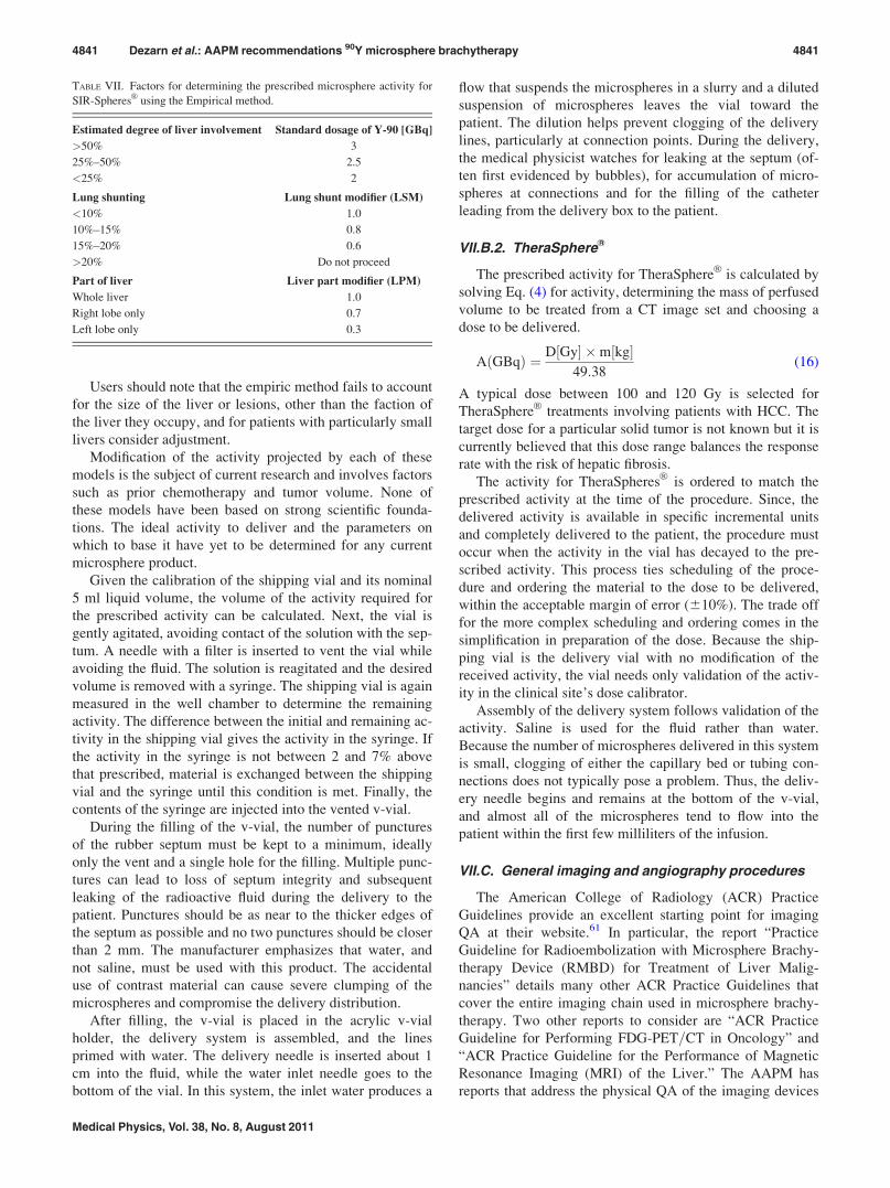
Users should note that the empiric method fails to account
for the size of the liver or lesions, other than the faction of
the liver they occupy, and for patients with particularly small
livers consider adjustment.
Modification of the activity projected by each of these
models is the subject of current research and involves factors
such as prior chemotherapy and tumor volume. None of
these models have been based on strong scientific founda-
tions. The ideal activity to deliver and the parameters on
which to base it have yet to be determined for any current
microsphere product.
Given the calibration of the shipping vial and its nominal
5 ml liquid volume, the volume of the activity required for
the prescribed activity can be calculated. Next, the vial is
gently agitated, avoiding contact of the solution with the sep-
tum. A needle with a filter is inserted to vent the vial while
avoiding the fluid. The solution is reagitated and the desired
volume is removed with a syringe. The shipping vial is again
measured in the well chamber to determine the remaining
activity. The difference between the initial and remaining ac-
tivity in the shipping vial gives the activity in the syringe. If
the activity in the syringe is not between 2 and 7% above
that prescribed, material is exchanged between the shipping
vial and the syringe until this condition is met. Finally, the
contents of the syringe are injected into the vented v-vial.
During the filling of the v-vial, the number of punctures
of the rubber septum must be kept to a minimum, ideally
only the vent and a single hole for the filling. Multiple punc-
tures can lead to loss of septum integrity and subsequent
leaking of the radioactive fluid during the delivery to the
patient. Punctures should be as near to the thicker edges of
the septum as possible and no two punctures should be closer
than 2 mm. The manufacturer emphasizes that water, and
not saline, must be used with this product. The accidental
use of contrast material can cause severe clumping of the
microspheres and compromise the delivery distribution.
After filling, the v-vial is placed in the acrylic v-vial
holder, the delivery system is assembled, and the lines
primed with water. The delivery needle is inserted about 1
cm into the fluid, while the water inlet needle goes to the
bottom of the vial. In this system, the inlet water produces a
flow that suspends the microspheres in a slurry and a diluted
suspension of microspheres leaves the vial toward the
patient. The dilution helps prevent clogging of the delivery
lines, particularly at connection points. During the delivery,
the medical physicist watches for leaking at the septum (of-
ten first evidenced by bubbles), for accumulation of micro-
spheres at connections and for the filling of the catheter
leading from the delivery box to the patient.
VII.B.2. TheraSphereVR
The prescribed activity for TheraSphereVR
is calculated by
solving Eq. (4) for activity, determining the mass of perfused
volume to be treated from a CT image set and choosing a
dose to be delivered.
AðGBqÞ ¼ D½Gy� �m½kg�49:38
(16)
A typical dose between 100 and 120 Gy is selected for
TheraSphereVR
treatments involving patients with HCC. The
target dose for a particular solid tumor is not known but it is
currently believed that this dose range balances the response
rate with the risk of hepatic fibrosis.
The activity for TheraSpheresVR
is ordered to match the
prescribed activity at the time of the procedure. Since, the
delivered activity is available in specific incremental units
and completely delivered to the patient, the procedure must
occur when the activity in the vial has decayed to the pre-
scribed activity. This process ties scheduling of the proce-
dure and ordering the material to the dose to be delivered,
within the acceptable margin of error (610%). The trade off
for the more complex scheduling and ordering comes in the
simplification in preparation of the dose. Because the ship-
ping vial is the delivery vial with no modification of the
received activity, the vial needs only validation of the activ-
ity in the clinical site’s dose calibrator.
Assembly of the delivery system follows validation of the
activity. Saline is used for the fluid rather than water.
Because the number of microspheres delivered in this system
is small, clogging of either the capillary bed or tubing con-
nections does not typically pose a problem. Thus, the deliv-
ery needle begins and remains at the bottom of the v-vial,
and almost all of the microspheres tend to flow into the
patient within the first few milliliters of the infusion.
VII.C. General imaging and angiography procedures
The American College of Radiology (ACR) Practice
Guidelines provide an excellent starting point for imaging
QA at their website.61 In particular, the report “Practice
Guideline for Radioembolization with Microsphere Brachy-
therapy Device (RMBD) for Treatment of Liver Malig-
nancies” details many other ACR Practice Guidelines that
cover the entire imaging chain used in microsphere brachy-
therapy. Two other reports to consider are “ACR Practice
Guideline for Performing FDG-PET=CT in Oncology” and
“ACR Practice Guideline for the Performance of Magnetic
Resonance Imaging (MRI) of the Liver.” The AAPM has
reports that address the physical QA of the imaging devices
TABLE VII. Factors for determining the prescribed microsphere activity for
SIR-SpheresVR
using the Empirical method.
Estimated degree of liver involvement Standard dosage of Y-90 [GBq]
>50% 3
25%–50% 2.5
<25% 2
Lung shunting Lung shunt modifier (LSM)
<10% 1.0
10%–15% 0.8
15%–20% 0.6
>20% Do not proceed
Part of liver Liver part modifier (LPM)
Whole liver 1.0
Right lobe only 0.7
Left lobe only 0.3
4841 Dezarn et al.: AAPM recommendations 90Y microsphere brachytherapy 4841
Medical Physics, Vol. 38, No. 8, August 2011
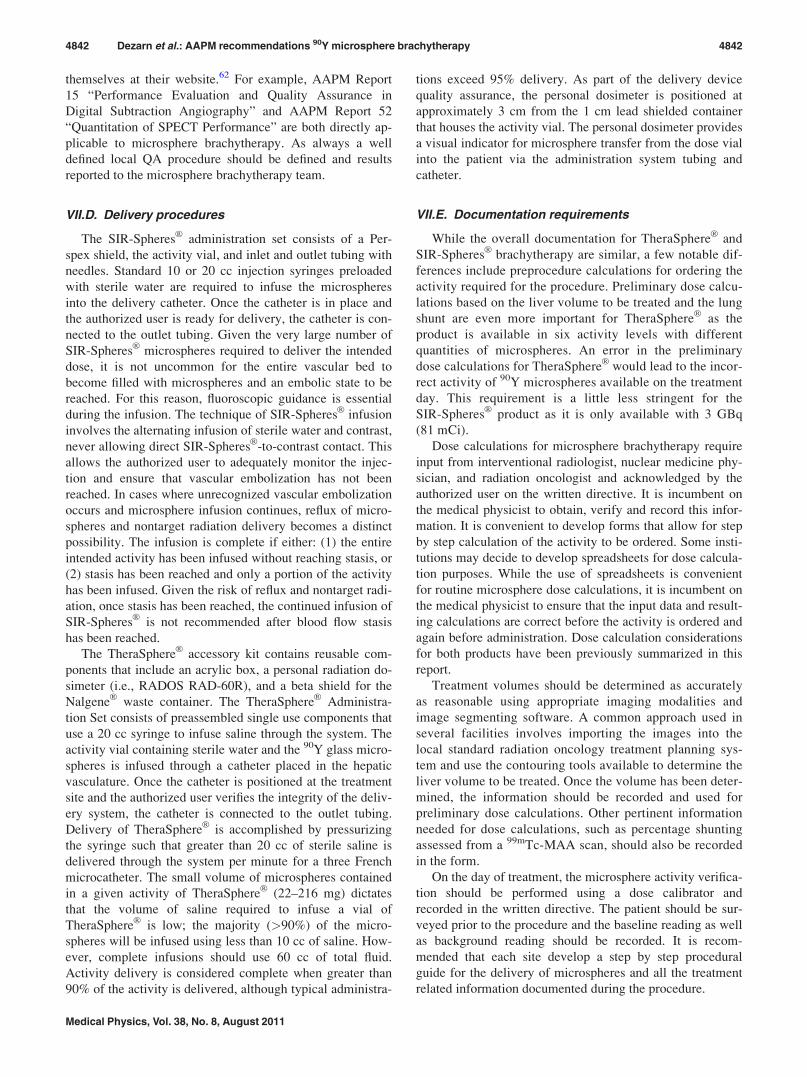
themselves at their website.62 For example, AAPM Report
15 “Performance Evaluation and Quality Assurance in
Digital Subtraction Angiography” and AAPM Report 52
“Quantitation of SPECT Performance” are both directly ap-
plicable to microsphere brachytherapy. As always a well
defined local QA procedure should be defined and results
reported to the microsphere brachytherapy team.
VII.D. Delivery procedures
The SIR-SpheresVR
administration set consists of a Per-
spex shield, the activity vial, and inlet and outlet tubing with
needles. Standard 10 or 20 cc injection syringes preloaded
with sterile water are required to infuse the microspheres
into the delivery catheter. Once the catheter is in place and
the authorized user is ready for delivery, the catheter is con-
nected to the outlet tubing. Given the very large number of
SIR-SpheresVR
microspheres required to deliver the intended
dose, it is not uncommon for the entire vascular bed to
become filled with microspheres and an embolic state to be
reached. For this reason, fluoroscopic guidance is essential
during the infusion. The technique of SIR-SpheresVR
infusion
involves the alternating infusion of sterile water and contrast,
never allowing direct SIR-SpheresVR
-to-contrast contact. This
allows the authorized user to adequately monitor the injec-
tion and ensure that vascular embolization has not been
reached. In cases where unrecognized vascular embolization
occurs and microsphere infusion continues, reflux of micro-
spheres and nontarget radiation delivery becomes a distinct
possibility. The infusion is complete if either: (1) the entire
intended activity has been infused without reaching stasis, or
(2) stasis has been reached and only a portion of the activity
has been infused. Given the risk of reflux and nontarget radi-
ation, once stasis has been reached, the continued infusion of
SIR-SpheresVR
is not recommended after blood flow stasis
has been reached.
The TheraSphereVR
accessory kit contains reusable com-
ponents that include an acrylic box, a personal radiation do-
simeter (i.e., RADOS RAD-60R), and a beta shield for the
NalgeneVR
waste container. The TheraSphereVR
Administra-
tion Set consists of preassembled single use components that
use a 20 cc syringe to infuse saline through the system. The
activity vial containing sterile water and the 90Y glass micro-
spheres is infused through a catheter placed in the hepatic
vasculature. Once the catheter is positioned at the treatment
site and the authorized user verifies the integrity of the deliv-
ery system, the catheter is connected to the outlet tubing.
Delivery of TheraSphereVR
is accomplished by pressurizing
the syringe such that greater than 20 cc of sterile saline is
delivered through the system per minute for a three French
microcatheter. The small volume of microspheres contained
in a given activity of TheraSphereVR
(22–216 mg) dictates
that the volume of saline required to infuse a vial of
TheraSphereVR
is low; the majority (>90%) of the micro-
spheres will be infused using less than 10 cc of saline. How-
ever, complete infusions should use 60 cc of total fluid.
Activity delivery is considered complete when greater than
90% of the activity is delivered, although typical administra-
tions exceed 95% delivery. As part of the delivery device
quality assurance, the personal dosimeter is positioned at
approximately 3 cm from the 1 cm lead shielded container
that houses the activity vial. The personal dosimeter provides
a visual indicator for microsphere transfer from the dose vial
into the patient via the administration system tubing and
catheter.
VII.E. Documentation requirements
While the overall documentation for TheraSphereVR
and
SIR-SpheresVR
brachytherapy are similar, a few notable dif-
ferences include preprocedure calculations for ordering the
activity required for the procedure. Preliminary dose calcu-
lations based on the liver volume to be treated and the lung
shunt are even more important for TheraSphereVR
as the
product is available in six activity levels with different
quantities of microspheres. An error in the preliminary
dose calculations for TheraSphereVR
would lead to the incor-
rect activity of 90Y microspheres available on the treatment
day. This requirement is a little less stringent for the
SIR-SpheresVR
product as it is only available with 3 GBq
(81 mCi).
Dose calculations for microsphere brachytherapy require
input from interventional radiologist, nuclear medicine phy-
sician, and radiation oncologist and acknowledged by the
authorized user on the written directive. It is incumbent on
the medical physicist to obtain, verify and record this infor-
mation. It is convenient to develop forms that allow for step
by step calculation of the activity to be ordered. Some insti-
tutions may decide to develop spreadsheets for dose calcula-
tion purposes. While the use of spreadsheets is convenient
for routine microsphere dose calculations, it is incumbent on
the medical physicist to ensure that the input data and result-
ing calculations are correct before the activity is ordered and
again before administration. Dose calculation considerations
for both products have been previously summarized in this
report.
Treatment volumes should be determined as accurately
as reasonable using appropriate imaging modalities and
image segmenting software. A common approach used in
several facilities involves importing the images into the
local standard radiation oncology treatment planning sys-
tem and use the contouring tools available to determine the
liver volume to be treated. Once the volume has been deter-
mined, the information should be recorded and used for
preliminary dose calculations. Other pertinent information
needed for dose calculations, such as percentage shunting
assessed from a 99mTc-MAA scan, should also be recorded
in the form.
On the day of treatment, the microsphere activity verifica-
tion should be performed using a dose calibrator and
recorded in the written directive. The patient should be sur-
veyed prior to the procedure and the baseline reading as well
as background reading should be recorded. It is recom-
mended that each site develop a step by step procedural
guide for the delivery of microspheres and all the treatment
related information documented during the procedure.
4842 Dezarn et al.: AAPM recommendations 90Y microsphere brachytherapy 4842
Medical Physics, Vol. 38, No. 8, August 2011
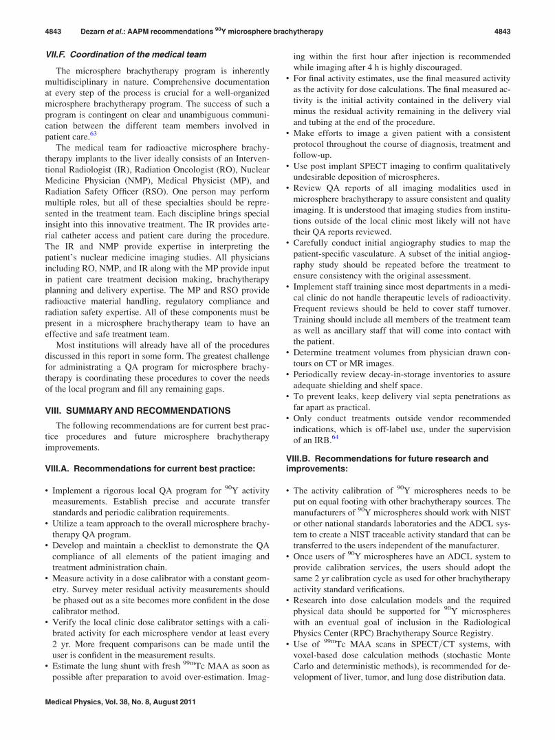
VII.F. Coordination of the medical team
The microsphere brachytherapy program is inherently
multidisciplinary in nature. Comprehensive documentation
at every step of the process is crucial for a well-organized
microsphere brachytherapy program. The success of such a
program is contingent on clear and unambiguous communi-
cation between the different team members involved in
patient care.63
The medical team for radioactive microsphere brachy-
therapy implants to the liver ideally consists of an Interven-
tional Radiologist (IR), Radiation Oncologist (RO), Nuclear
Medicine Physician (NMP), Medical Physicist (MP), and
Radiation Safety Officer (RSO). One person may perform
multiple roles, but all of these specialties should be repre-
sented in the treatment team. Each discipline brings special
insight into this innovative treatment. The IR provides arte-
rial catheter access and patient care during the procedure.
The IR and NMP provide expertise in interpreting the
patient’s nuclear medicine imaging studies. All physicians
including RO, NMP, and IR along with the MP provide input
in patient care treatment decision making, brachytherapy
planning and delivery expertise. The MP and RSO provide
radioactive material handling, regulatory compliance and
radiation safety expertise. All of these components must be
present in a microsphere brachytherapy team to have an
effective and safe treatment team.
Most institutions will already have all of the procedures
discussed in this report in some form. The greatest challenge
for administrating a QA program for microsphere brachy-
therapy is coordinating these procedures to cover the needs
of the local program and fill any remaining gaps.
VIII. SUMMARY AND RECOMMENDATIONS
The following recommendations are for current best prac-
tice procedures and future microsphere brachytherapy
improvements.
VIII.A. Recommendations for current best practice:
• Implement a rigorous local QA program for 90Y activity
measurements. Establish precise and accurate transfer
standards and periodic calibration requirements.• Utilize a team approach to the overall microsphere brachy-
therapy QA program.• Develop and maintain a checklist to demonstrate the QA
compliance of all elements of the patient imaging and
treatment administration chain.• Measure activity in a dose calibrator with a constant geom-
etry. Survey meter residual activity measurements should
be phased out as a site becomes more confident in the dose
calibrator method.• Verify the local clinic dose calibrator settings with a cali-
brated activity for each microsphere vendor at least every
2 yr. More frequent comparisons can be made until the
user is confident in the measurement results.• Estimate the lung shunt with fresh 99mTc MAA as soon as
possible after preparation to avoid over-estimation. Imag-
ing within the first hour after injection is recommended
while imaging after 4 h is highly discouraged.• For final activity estimates, use the final measured activity
as the activity for dose calculations. The final measured ac-
tivity is the initial activity contained in the delivery vial
minus the residual activity remaining in the delivery vial
and tubing at the end of the procedure.• Make efforts to image a given patient with a consistent
protocol throughout the course of diagnosis, treatment and
follow-up.• Use post implant SPECT imaging to confirm qualitatively
undesirable deposition of microspheres.• Review QA reports of all imaging modalities used in
microsphere brachytherapy to assure consistent and quality
imaging. It is understood that imaging studies from institu-
tions outside of the local clinic most likely will not have
their QA reports reviewed.• Carefully conduct initial angiography studies to map the
patient-specific vasculature. A subset of the initial angiog-
raphy study should be repeated before the treatment to
ensure consistency with the original assessment.• Implement staff training since most departments in a medi-
cal clinic do not handle therapeutic levels of radioactivity.
Frequent reviews should be held to cover staff turnover.
Training should include all members of the treatment team
as well as ancillary staff that will come into contact with
the patient.• Determine treatment volumes from physician drawn con-
tours on CT or MR images.• Periodically review decay-in-storage inventories to assure
adequate shielding and shelf space.• To prevent leaks, keep delivery vial septa penetrations as
far apart as practical.• Only conduct treatments outside vendor recommended
indications, which is off-label use, under the supervision
of an IRB.64
VIII.B. Recommendations for future research andimprovements:
• The activity calibration of 90Y microspheres needs to be
put on equal footing with other brachytherapy sources. The
manufacturers of 90Y microspheres should work with NIST
or other national standards laboratories and the ADCL sys-
tem to create a NIST traceable activity standard that can be
transferred to the users independent of the manufacturer.• Once users of 90Y microspheres have an ADCL system to
provide calibration services, the users should adopt the
same 2 yr calibration cycle as used for other brachytherapy
activity standard verifications.• Research into dose calculation models and the required
physical data should be supported for 90Y microspheres
with an eventual goal of inclusion in the Radiological
Physics Center (RPC) Brachytherapy Source Registry.• Use of 99mTc MAA scans in SPECT=CT systems, with
voxel-based dose calculation methods (stochastic Monte
Carlo and deterministic methods), is recommended for de-
velopment of liver, tumor, and lung dose distribution data.
4843 Dezarn et al.: AAPM recommendations 90Y microsphere brachytherapy 4843
Medical Physics, Vol. 38, No. 8, August 2011
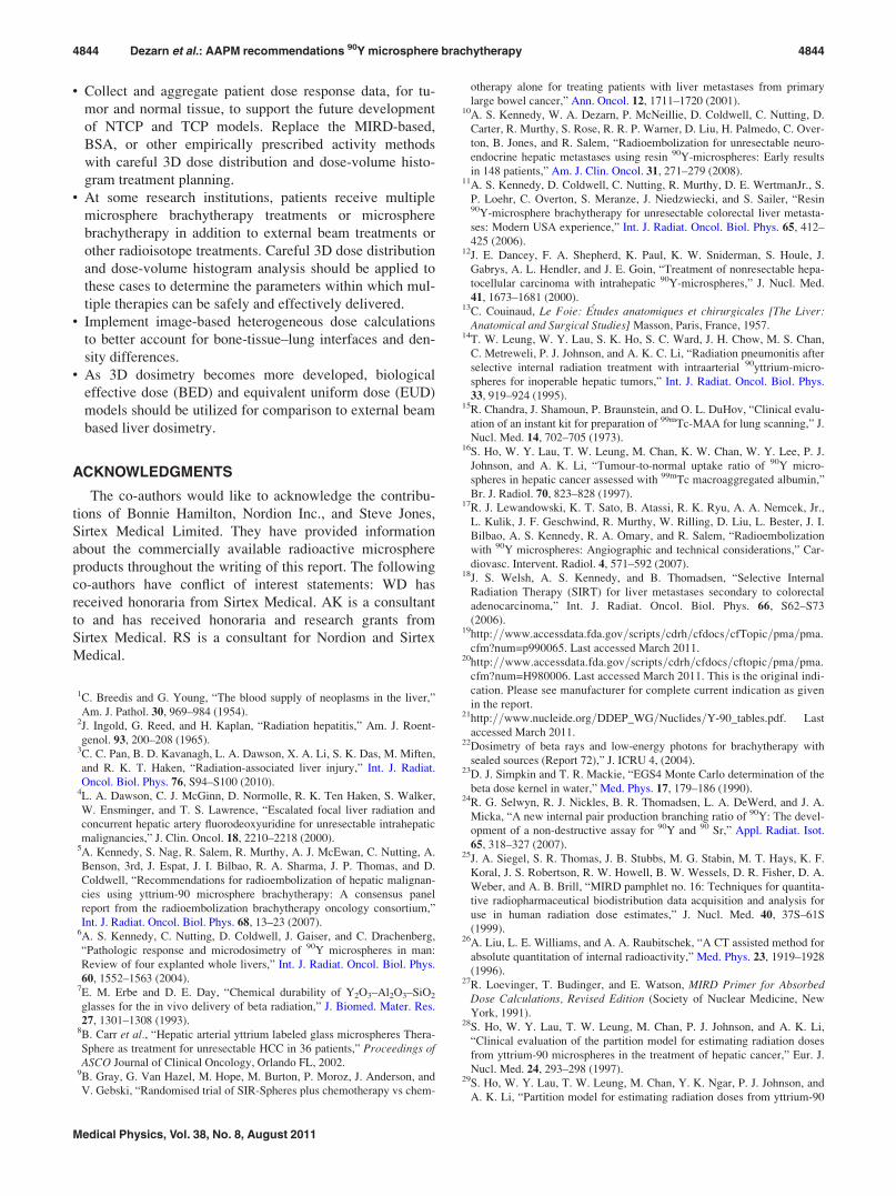
• Collect and aggregate patient dose response data, for tu-
mor and normal tissue, to support the future development
of NTCP and TCP models. Replace the MIRD-based,
BSA, or other empirically prescribed activity methods
with careful 3D dose distribution and dose-volume histo-
gram treatment planning.• At some research institutions, patients receive multiple
microsphere brachytherapy treatments or microsphere
brachytherapy in addition to external beam treatments or
other radioisotope treatments. Careful 3D dose distribution
and dose-volume histogram analysis should be applied to
these cases to determine the parameters within which mul-
tiple therapies can be safely and effectively delivered.• Implement image-based heterogeneous dose calculations
to better account for bone-tissue–lung interfaces and den-
sity differences.• As 3D dosimetry becomes more developed, biological
effective dose (BED) and equivalent uniform dose (EUD)
models should be utilized for comparison to external beam
based liver dosimetry.
ACKNOWLEDGMENTS
The co-authors would like to acknowledge the contribu-
tions of Bonnie Hamilton, Nordion Inc., and Steve Jones,
Sirtex Medical Limited. They have provided information
about the commercially available radioactive microsphere
products throughout the writing of this report. The following
co-authors have conflict of interest statements: WD has
received honoraria from Sirtex Medical. AK is a consultant
to and has received honoraria and research grants from
Sirtex Medical. RS is a consultant for Nordion and Sirtex
Medical.
1C. Breedis and G. Young, “The blood supply of neoplasms in the liver,”
Am. J. Pathol. 30, 969–984 (1954).2J. Ingold, G. Reed, and H. Kaplan, “Radiation hepatitis,” Am. J. Roent-
genol. 93, 200–208 (1965).3C. C. Pan, B. D. Kavanagh, L. A. Dawson, X. A. Li, S. K. Das, M. Miften,
and R. K. T. Haken, “Radiation-associated liver injury,” Int. J. Radiat.
Oncol. Biol. Phys. 76, S94–S100 (2010).4L. A. Dawson, C. J. McGinn, D. Normolle, R. K. Ten Haken, S. Walker,
W. Ensminger, and T. S. Lawrence, “Escalated focal liver radiation and
concurrent hepatic artery fluorodeoxyuridine for unresectable intrahepatic
malignancies,” J. Clin. Oncol. 18, 2210–2218 (2000).5A. Kennedy, S. Nag, R. Salem, R. Murthy, A. J. McEwan, C. Nutting, A.
Benson, 3rd, J. Espat, J. I. Bilbao, R. A. Sharma, J. P. Thomas, and D.
Coldwell, “Recommendations for radioembolization of hepatic malignan-
cies using yttrium-90 microsphere brachytherapy: A consensus panel
report from the radioembolization brachytherapy oncology consortium,”
Int. J. Radiat. Oncol. Biol. Phys. 68, 13–23 (2007).6A. S. Kennedy, C. Nutting, D. Coldwell, J. Gaiser, and C. Drachenberg,
“Pathologic response and microdosimetry of 90Y microspheres in man:
Review of four explanted whole livers,” Int. J. Radiat. Oncol. Biol. Phys.
60, 1552–1563 (2004).7E. M. Erbe and D. E. Day, “Chemical durability of Y2O3–Al2O3–SiO2
glasses for the in vivo delivery of beta radiation,” J. Biomed. Mater. Res.
27, 1301–1308 (1993).8B. Carr et al., “Hepatic arterial yttrium labeled glass microspheres Thera-
Sphere as treatment for unresectable HCC in 36 patients,” Proceedings ofASCO Journal of Clinical Oncology, Orlando FL, 2002.
9B. Gray, G. Van Hazel, M. Hope, M. Burton, P. Moroz, J. Anderson, and
V. Gebski, “Randomised trial of SIR-Spheres plus chemotherapy vs chem-
otherapy alone for treating patients with liver metastases from primary
large bowel cancer,” Ann. Oncol. 12, 1711–1720 (2001).10A. S. Kennedy, W. A. Dezarn, P. McNeillie, D. Coldwell, C. Nutting, D.
Carter, R. Murthy, S. Rose, R. R. P. Warner, D. Liu, H. Palmedo, C. Over-
ton, B. Jones, and R. Salem, “Radioembolization for unresectable neuro-
endocrine hepatic metastases using resin 90Y-microspheres: Early results
in 148 patients,” Am. J. Clin. Oncol. 31, 271–279 (2008).11A. S. Kennedy, D. Coldwell, C. Nutting, R. Murthy, D. E. WertmanJr., S.
P. Loehr, C. Overton, S. Meranze, J. Niedzwiecki, and S. Sailer, “Resin90Y-microsphere brachytherapy for unresectable colorectal liver metasta-
ses: Modern USA experience,” Int. J. Radiat. Oncol. Biol. Phys. 65, 412–
425 (2006).12J. E. Dancey, F. A. Shepherd, K. Paul, K. W. Sniderman, S. Houle, J.
Gabrys, A. L. Hendler, and J. E. Goin, “Treatment of nonresectable hepa-
tocellular carcinoma with intrahepatic 90Y-microspheres,” J. Nucl. Med.
41, 1673–1681 (2000).13C. Couinaud, Le Foie: Etudes anatomiques et chirurgicales [The Liver:
Anatomical and Surgical Studies] Masson, Paris, France, 1957.14T. W. Leung, W. Y. Lau, S. K. Ho, S. C. Ward, J. H. Chow, M. S. Chan,
C. Metreweli, P. J. Johnson, and A. K. C. Li, “Radiation pneumonitis after
selective internal radiation treatment with intraarterial 90yttrium-micro-
spheres for inoperable hepatic tumors,” Int. J. Radiat. Oncol. Biol. Phys.
33, 919–924 (1995).15R. Chandra, J. Shamoun, P. Braunstein, and O. L. DuHov, “Clinical evalu-
ation of an instant kit for preparation of 99mTc-MAA for lung scanning,” J.
Nucl. Med. 14, 702–705 (1973).16S. Ho, W. Y. Lau, T. W. Leung, M. Chan, K. W. Chan, W. Y. Lee, P. J.
Johnson, and A. K. Li, “Tumour-to-normal uptake ratio of 90Y micro-
spheres in hepatic cancer assessed with 99mTc macroaggregated albumin,”
Br. J. Radiol. 70, 823–828 (1997).17R. J. Lewandowski, K. T. Sato, B. Atassi, R. K. Ryu, A. A. Nemcek, Jr.,
L. Kulik, J. F. Geschwind, R. Murthy, W. Rilling, D. Liu, L. Bester, J. I.
Bilbao, A. S. Kennedy, R. A. Omary, and R. Salem, “Radioembolization
with 90Y microspheres: Angiographic and technical considerations,” Car-
diovasc. Intervent. Radiol. 4, 571–592 (2007).18J. S. Welsh, A. S. Kennedy, and B. Thomadsen, “Selective Internal
Radiation Therapy (SIRT) for liver metastases secondary to colorectal
adenocarcinoma,” Int. J. Radiat. Oncol. Biol. Phys. 66, S62–S73
(2006).19http:==www.accessdata.fda.gov=scripts=cdrh=cfdocs=cfTopic=pma=pma.
cfm?num=p990065. Last accessed March 2011.20http:==www.accessdata.fda.gov=scripts=cdrh=cfdocs=cftopic=pma=pma.
cfm?num=H980006. Last accessed March 2011. This is the original indi-
cation. Please see manufacturer for complete current indication as given
in the report.21http:==www.nucleide.org=DDEP_WG=Nuclides=Y-90_tables.pdf. Last
accessed March 2011.22Dosimetry of beta rays and low-energy photons for brachytherapy with
sealed sources (Report 72),” J. ICRU 4, (2004).23D. J. Simpkin and T. R. Mackie, “EGS4 Monte Carlo determination of the
beta dose kernel in water,” Med. Phys. 17, 179–186 (1990).24R. G. Selwyn, R. J. Nickles, B. R. Thomadsen, L. A. DeWerd, and J. A.
Micka, “A new internal pair production branching ratio of 90Y: The devel-
opment of a non-destructive assay for 90Y and 90 Sr,” Appl. Radiat. Isot.
65, 318–327 (2007).25J. A. Siegel, S. R. Thomas, J. B. Stubbs, M. G. Stabin, M. T. Hays, K. F.
Koral, J. S. Robertson, R. W. Howell, B. W. Wessels, D. R. Fisher, D. A.
Weber, and A. B. Brill, “MIRD pamphlet no. 16: Techniques for quantita-
tive radiopharmaceutical biodistribution data acquisition and analysis for
use in human radiation dose estimates,” J. Nucl. Med. 40, 37S–61S
(1999).26A. Liu, L. E. Williams, and A. A. Raubitschek, “A CT assisted method for
absolute quantitation of internal radioactivity,” Med. Phys. 23, 1919–1928
(1996).27R. Loevinger, T. Budinger, and E. Watson, MIRD Primer for Absorbed
Dose Calculations, Revised Edition (Society of Nuclear Medicine, New
York, 1991).28S. Ho, W. Y. Lau, T. W. Leung, M. Chan, P. J. Johnson, and A. K. Li,
“Clinical evaluation of the partition model for estimating radiation doses
from yttrium-90 microspheres in the treatment of hepatic cancer,” Eur. J.
Nucl. Med. 24, 293–298 (1997).29S. Ho, W. Y. Lau, T. W. Leung, M. Chan, Y. K. Ngar, P. J. Johnson, and
A. K. Li, “Partition model for estimating radiation doses from yttrium-90
4844 Dezarn et al.: AAPM recommendations 90Y microsphere brachytherapy 4844
Medical Physics, Vol. 38, No. 8, August 2011
microspheres in treating hepatic tumours,” Eur. J. Nucl. Med. 23, 947–952
(1996).30M. G. Stabin, “Update: The case for patient-specific dosimetry in radionu-
clide therapy,” Cancer Biother. Radiopharm. 23, 273–284 (2008).31K. S. Kolbert, G. Sgouros, A. M. Scott, J. E. Bronstein, R. A. Malane, J.
Zhang, H. Kalaigian, S. McNamara, L. Schwartz, and S. M. Larson,
“Implementation and evaluation of patient-specific three-dimensional in-
ternal dosimetry,” J. Nucl. Med. 38, 301–308 (1997).32Y. K. Dewaraja, S. J. Wilderman, M. Ljungberg, K. F. Koral, K. Zasadny,
and M. S. Kaminiski, “Accurate dosimetry in 131I radionuclide therapy
using patient-specific, 3-dimensional methods for SPECT reconstruction
and absorbed dose calculation,” J. Nucl. Med. 46, 840–849 (2005).33A. Liu, L. E. Williams, G. Lopatin, D. M. Yamauchi, J. Y. C. Wong, and
A. A. Raubitschek, “A radionuclide therapy treatment planning and dose
estimation system,” J. Nucl. Med. 40, 1151–1153 (1999).34M. J. Guy, G. D. Flux, P. Papavasileiou, M. A. Flower, and R. J. Ott,
“RMDP: A dedicated package for 131I SPECT quantification, registration
and patient-specific dosimetry,” Cancer Biother. Radiopharm. 18, 61–69
(2003).35I. Clairand, M. Ricard, J. Gouriou, M. Di Paola, and B. Aubert, “DOSE3D:
EGS4 Monte Carlo code-based software for internal radionuclide dos-
imetry,” J. Nucl. Med. 40, 1517–1523 (1999).36J. Lehmann, C. H. Siantar, D. E. Wessol, C. A. Wemple, D. Nigg, J.
Cogliati, T. Daly, M. -A. Descalle, T. Flickinger, D. Pletcher, and G.
DeNardo, “Monte Carlo treatment planning for molecular targeted radio-
therapy within the MINERVA system,” Phys. Med. Biol. 50, 947–958
(2005).37T. Wareing, J. McGhee, J. Morel, and S. Pautz, “Discontinuous finite ele-
ment SN methods on three-dimensional unstructured grids,” Nucl. Sci.
Eng. 138, 256–268 (2001).38J. Mikell, O. Vassiliev, W. Erwin, T. Wareing, and F. Mourtada,
“Comparing a grid-based Boltzmann solver with Monte Carlo simulation
for voxel-based therapeutic radionuclide dose calculations,” Med. Phys.
36, 2772 (2009).39A. K. Erdi, E. D. Yorke, M. H. Loew, Y. E. Erdi, M. Sarfaraz, and B. W.
Wessels, “Use of the fast Hartley transform for three-dimensional dose
calculation in radionuclide therapy,” Med. Phys. 25, 2226–2233 (1998).40http:==www.doseinfo-radar.com=RADARServices.html. Last accessed
March 2011.41D. J. Simpkin, S. J. Cullom, and T. R. Mackie, “The spatial and energy de-
pendence of bremsstrahlung production about beta point sources in H2O,”
Med. Phys. 19, 105–114 (1992).42W. E. Bolch, L. G. Bouchet, J. S. Robertson, B. W. Wessels, J. A. Siegel,
R. W. Howell, A. K. Erdi, B. Aydogan, S. Costes, E. E. Watson, A. B.
Brill, N. D. Charkes, D. R. Fisher, M. T. Hays, and S. R. Thomas, “MIRD
pamphlet no. 17: The dosimetry of nonuniform activity distributions-radi-
onuclide S values at the voxel level. Medical Internal Radiation Dose
Committee,” J. Nucl. Med. 40, 11–S36S (1999).43M. Sarfaraz, A. S. Kennedy, M. A. Lodge, X. A. Li, X. Wu, and C. X. Yu,
“Radiation absorbed dose distribution in a patient treated with yttrium-90
microspheres for hepatocellular carcinoma,” Med. Phys. 31, 2449–2453
(2004).44G. L. DeNardo, D. J. Macey, S. J. DeNardo, C. G. Zhang, and T. R. Cus-
ter, “Quantitative SPECT of uptake of monoclonal antibodies,” Semin.
Nucl. Med. 19, 22–32 (1989).45K. F. Koral, Y. Dewaraja, J. Li, Q. Lin, D. D. Regan, K. R. Zasadny, S. G.
Rommelfanger, I. R. Francis, M. S. Kaminski, and R. L. Wahl, “Update
on hybrid conjugate-view SPECT tumor dosimetry and response in
131I-Tositumomab therapy of previously untreated lymphoma patients,” J.
Nucl. Med. 44, 457–464 (2003).46B. E. Zimmerman and R. Colle, “Standardization of 63Ni by 4pb liquid
scintillation spectrometry with 3H-standard efficiency tracing,” J. Res.
Natl. Inst. Stand. Technol. 102, 455–477 (1997).47K. Kossert and H. Schrader, “Activity standardization by liquid scintilla-
tion counting and half-life measurements of 90Y,” Appl. Radiat. Isot. 60,
741–749 (2004).48B. E. Zimmerman, R. Colle, and J. T. Cessna, “Construction and imple-
mentation of the NIST triple-to-double coincidence ratio (TDCR)
spectrometer,” Appl. Radiat. Isot. 60, 433–438 (2004).49B. E. Zimmerman and G. Ratel, “Report of the CIPM key comparison
CCRI(II)-K2.Y-90,” Metrologia 42, 06001 (2005).50L. Mo, B. Avci, D. James, B. Simpson, W. M. Van Wyngaardt, J. T.
Cessna, and C. Baldock, “Development of activity standard for90Y micro-
spheres,” Appl. Radiat. Isot. 63, 193–199 (2005).51R. Selwyn, J. Micka, L. DeWerd, R. Nickles, and B. Thomadsen,
“Technical note: The calibration of 90Y-labeled SIR-SpheresVR
using a
nondestructive spectroscopic assay,” Med. Phys. 35, 1278–1279 (2008).52B. M. Coursey, J. M. Calhoun, and J. T. Cessna, “Radioassays of yttrium-
90 used in nuclear medicine,” Nucl. Med. Biol. 20, 693–699 (1993).53J. A. Siegel, B. E. Zimmerman, K. Kodimer, M. A. Dell, and W. E. Simon,
“Accurate dose calibrator activity measurement of 90Y-ibritumomab
tiuxetan,” J. Nucl. Med. 45, 450–454 (2004).54B. E. Zimmerman, J. T. Cessna, and M. A. Millican, “Experimental deter-
mination of calibration settings for plastic syringes containing solutions of90Y using commercial radionuclide calibrators,” Appl. Radiat. Isot. 60,
511–517 (2004).55W. Dezarn and A. Kennedy, “SU-FF-T-380: Significant differences exist
across institutions in 90Y activities compared to reference standard,” Med.
Phys. 34, 2489 (2007).56W. A. Dezarn and A. S. Kennedy, “Resin 90Y microsphere activity
measurements for liver brachytherapy,” Med. Phys. 34, 1896–1900
(2007).57http:==www.nrc.gov=materials=miau=med-use-toolkit.html. Last accessed
March 2011. Follow links given under heading ‘Other Guidance’.58R. Salem and K. G. Thurston, “Radioembolization with 90Yttrium micro-
spheres: A state-of-the-art brachytherapy treatment for primary and
secondary liver malignancies. Part1: Technical and methodologic consid-
erations,” J. Vasc. Interv. Radiol. 17, 1251–1278 (2006).59S. Nag, R. Dobelbower, G. Glasgow, G. Gustafson, N. Syed, B. Thomad-
sen, and J. F. Williamson, “Inter-society standards for the performance of
brachytherapy: A joint report from ABS, ACMP and ACRO,” Crit. Rev.
Oncol.=Hematol. 48, 1–17 (2003).60IAEA, “Quality assurance for radioactivity measurement in nuclear medi-
cine,” International Atomic Energy Agency Technical Report Series No.
454 (2006).61http:==acr.org=SecondaryMainMenuCategories=quality_safety=guidelines=
toc.aspx. Last accessed March 2011.62http:==www.aapm.org=pubs=reports. Last accessed March 2011.63W. A. Dezarn, “Quality assurance issues for therapeutic application of ra-
dioactive microspheres,” Int. J. Radiat. Oncol. Biol. Phys. 71, S147–S151
(2008).64B. R. Thomadsen, H. T. Heaton II, S. K. Jani, J. P. Masten, M. E. Napoli-
tano, Z. Ouhib, C. S. Reft, M. J. Rivard, T. T. Robin, M. Subramanian,
and O. H. Suleiman, “Off-label use of medical products in radiation ther-
apy: Summary of the report of AAPM task group no. 121,” Med. Phys. 37,
2300–2311 (2010).
4845 Dezarn et al.: AAPM recommendations 90Y microsphere brachytherapy 4845
Medical Physics, Vol. 38, No. 8, August 2011