reducing condensation thermal with fluid applied...
TRANSCRIPT
Reducing Condensation & Thermal Bridging with Fluid‐Applied Coatings

Tnemec Company, Inc. is a Registered Provider with The American Institute of Architects Continuing Education Systems. Credit earned on completion of this program will be reported to CES Records for AIA members. Certificates of Completion for non‐AIA members are available on request.
This program is registered with the AIA/CES for continuing professional education. As such, it does not include content that may be deemed or construed to be an approval or endorsement by the AIA of any material of construction or any method or manner of handling, using, distributing, or dealing in any material or product. Questions related to specific materials, methods, and services will be addressed at the conclusion of this presentation.

Tnemec Company, Inc. has met the standards and requirements of the NCEES Registered Continuing Education Program. Credit earned on completion of thisprogram will be reported to RCEP. A certificate ofcompletion will be issued to each participant.

Copyright MaterialsThis educational activity is protected by U.S. and International Copyright laws. Reproduction, distribution, display, and use of the educational activity without written permission of the presenter is prohibited.
© Tnemec Company, Inc. 2014

Course DescriptionIt has become more and more evident that the performance of thebuilding envelope can be greatly affected by thermal bridging. Thispresentation will discuss the use of fluid‐applied coatings as a newand innovative solution to minimize thermal bridging in both new and existing buildings. We will cover some key areas of concern where a fluid‐applied coating can be utilized without altering the structural design elements of the building.
This course is worth : 1.0 LU
Learning Objectives• Provide novel solutions for reducing condensation within the
building envelope with fluid‐applied coatings. • Explain areas within a building interior and exterior where
thermal bridging is a concern.• Demonstrate benefits of using a fluid‐applied coating as a
solution for Thermal Bridging. • Discuss standards which address continuous insulation (i.e.
ASHRAE 90.1‐2010).

Course Topics • Overview of Insulation Coatings• Thermal Bridging
– What is it?– Possible solutions
• Thermal Study• Summary and Questions

INSULATION COATINGS

Insulation Coatings
• Coatings formulated with insulative fillers to produce a low conductivity material– Ceramic or glass spheres
• Thermal conductivity in the 70 – 100 mW/mK range– Aerogel particles
• Thermal conductivity as low as 35 mW/mK

Insulation Coating Uses
• Personnel Protection• Energy Efficiency• CUI Prevention• Condensation Control
– New concept for mitigating Thermal Bridging
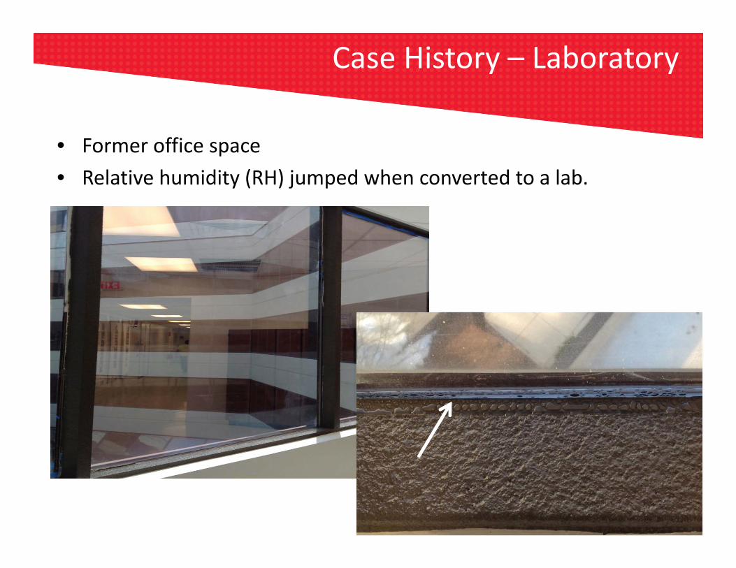
Case History – Laboratory
• Former office space• Relative humidity (RH) jumped when converted to a lab.

IR Tells the Story
• Window with 110 mils of Aerogel coating• 20°C (68.5°F) surface temp• Exterior Temperature ‐2°C (28°F)
• Window gasket with no Aerogel coating • 8°C (47.1°F) surface temp• Exterior Temperature ‐2°C (28°F)

THERMAL BRIDGINGAerogel Insulating Coating

What is Thermal Bridging?
• Highly conductive materials that bypass the insulating layer.• Areas of high heat.• Can greatly affect the thermal performance of assemblies.

Why Care about Thermal Bridging?
• Heat flows determine:• Heating and cooling system capacity• Purchased energy requirements• Compliance with energy codes • Compliance with voluntary energy programs
• Arrangement of materials determine:• Surface temperatures • Condensation and moisture collection• Durability• Mold growth and health issues

Five Years Ago…
Research Project 1365‐RP
• Extensively validated a 3D heat transfer model and procedures to measured data.
• Borrowed a methodology from Europe and applied to North American practice.
• Started a catalogue of thermal performance data.

Five Years Ago…
North American Data and Procedures in Energy Standards Pre‐date 1365‐RP
Computer Modeling
Hand Calculations
Lab Measurement
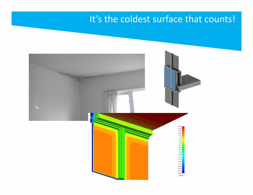
It’s the coldest surface that counts!

Building Envelope Thermal Bridging Guide

1365‐RP and Beyond
• Connecting the dots
Whole Building Energy Analysis
Construction Cost Analysis
Thermal Performance
Cost Benefit Analysis

Why Moving beyond Parallel Path Assumptions?
• Parallel path doesn’t tell the whole story.
• Many thermal bridges don’t abide by “areas”.
• Parallel paths often don’t capture temperature distribution.
• A level playing field will be created when all thermal bridges are thoroughly evaluated.
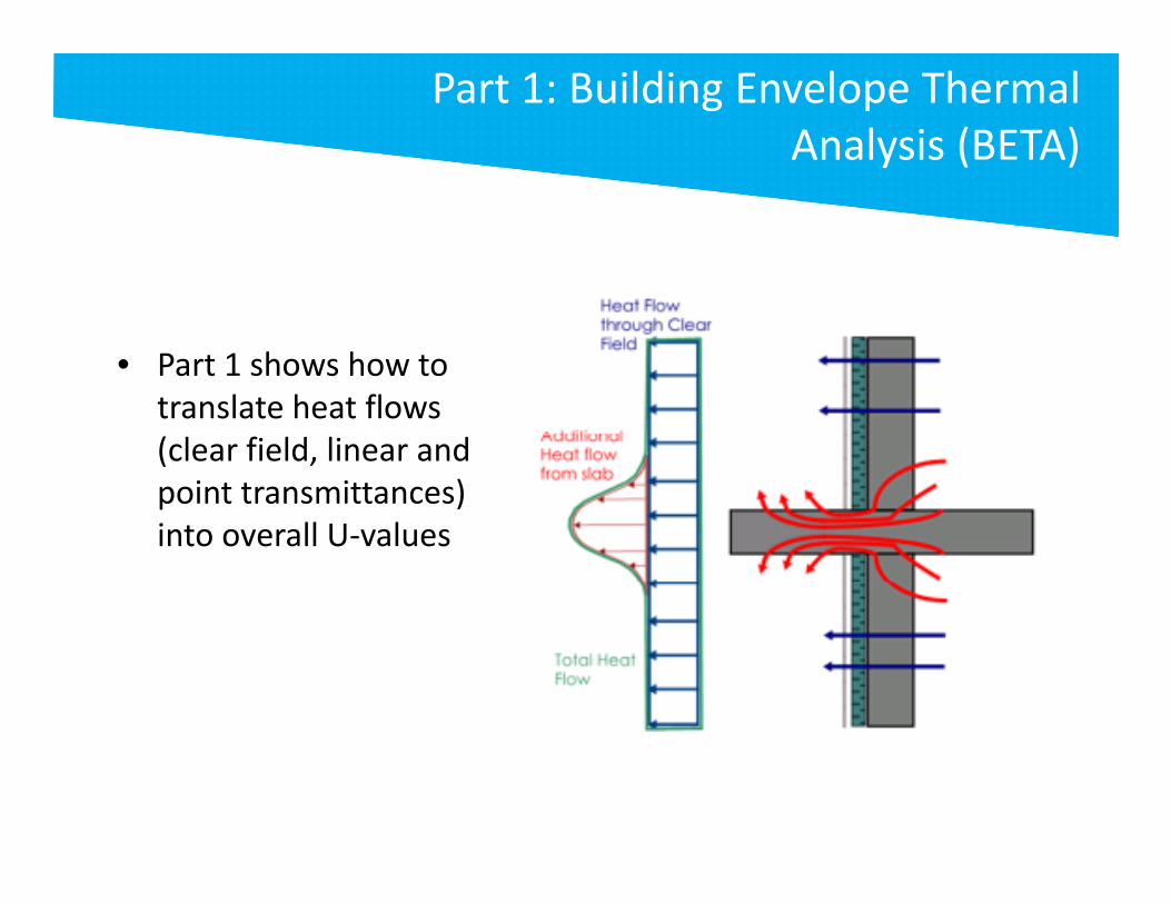
Part 1: Building Envelope Thermal Analysis (BETA)
• Part 1 shows how to translate heat flows (clear field, linear and point transmittances) into overall U‐values

Overall Heat Loss
Additional heat loss due to the slab
oQQ slabQ

LQslab /
Linear Transmittance represents the additional heat flow because of the slab, but with area set to zero
Overall Heat Loss
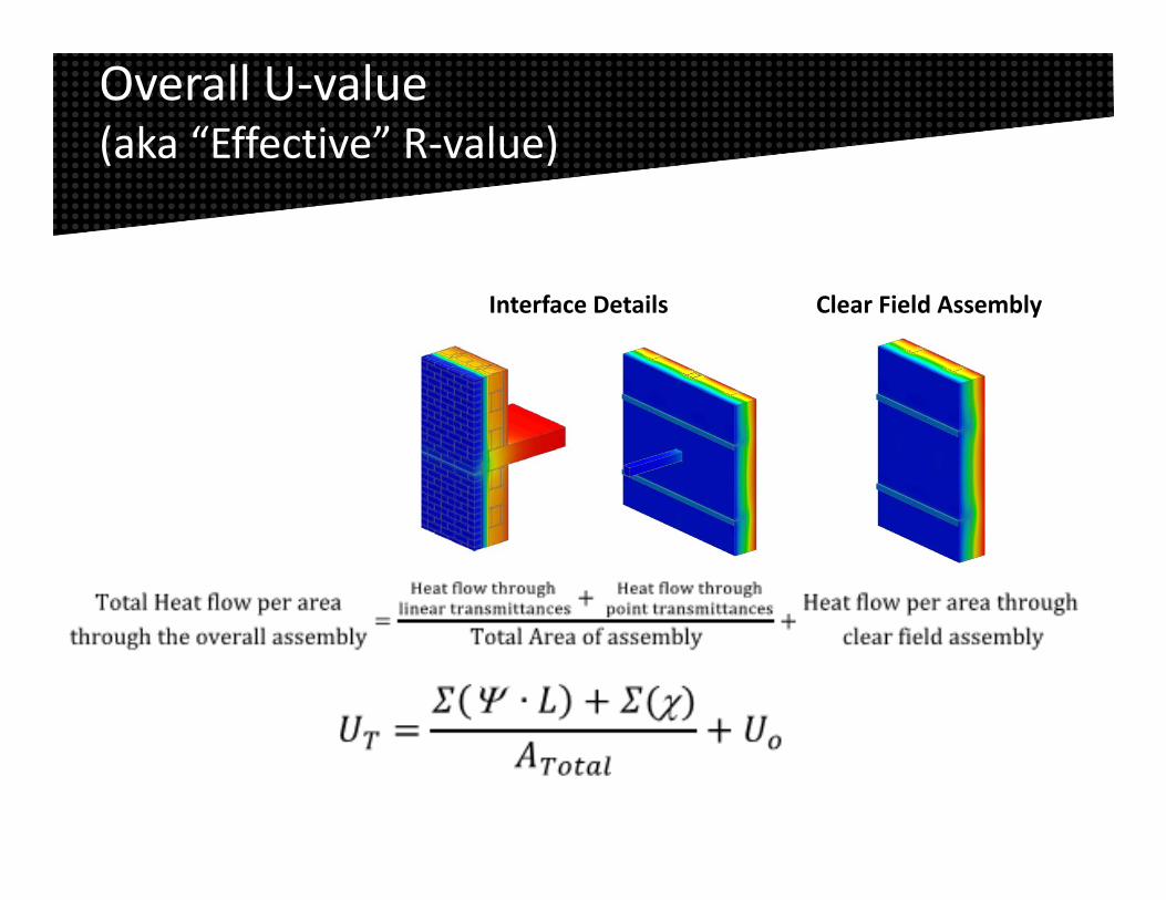
Overall U‐value (aka “Effective” R‐value)
Interface Details Clear Field Assembly
Overall U‐value (aka “Effective” R‐value)

Condensation Risk
Ti = 0.54
outsideinside
outsidesurfacei TT
TTT
Indoor Temperature
Outdoor Temperature
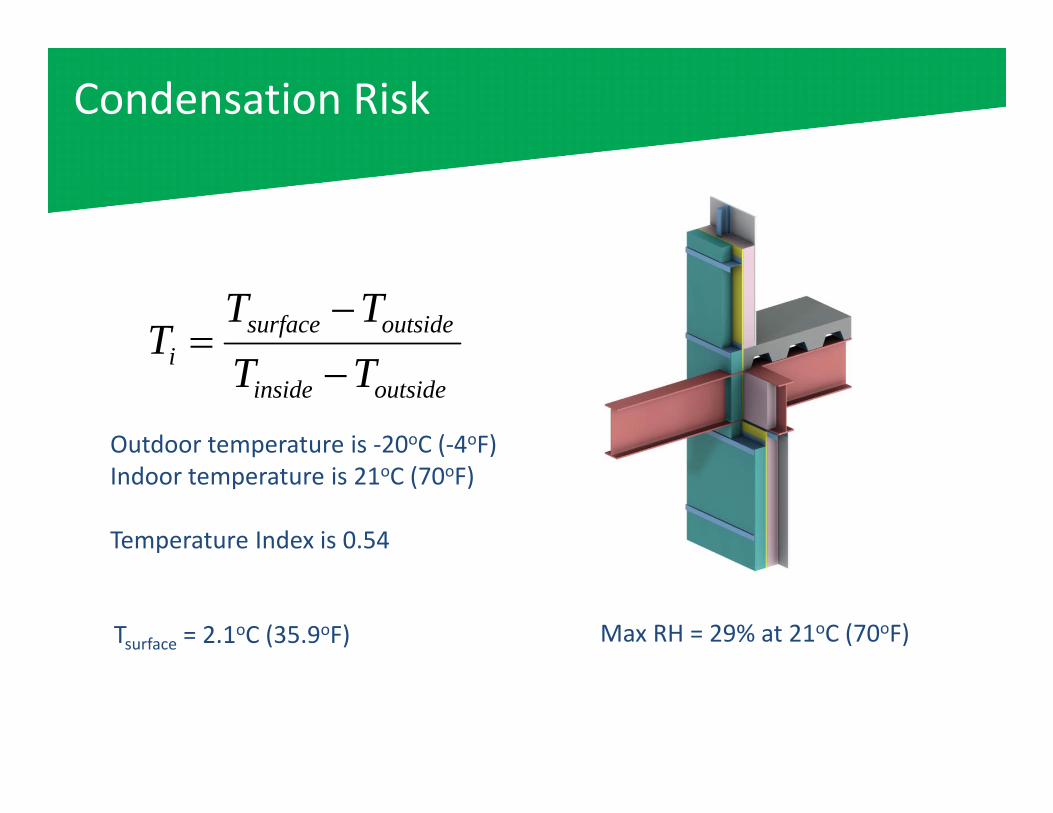
Tsurface = 2.1oC (35.9oF)
Outdoor temperature is ‐20oC (‐4oF)Indoor temperature is 21oC (70oF)
Temperature Index is 0.54
outsideinside
outsidesurfacei TT
TTT
Max RH = 29% at 21oC (70oF)
Condensation Risk

• Glazing is typically the thermal weak point and coldest surface that is directly in contact with the interior air
• Moisture levels should be controlled to prevent excessive condensation on commonly available, good quality, windows
Condensation Risk

Heat Flow and Condensation Risk
Heat Flow and Condensation Risk

Appendix A and B

Aerogel Coatings
No Coating With Coating
Temperature Index 0.54 0.62
Surface Temperature 11°F Exterior and 70°F Interior
35.9oF (2.1oC)
41.8oF (5.4oC)
Maximum Allowable Indoor RH at 70°F 29% 36%

THERMAL TEST STUDYAerogel Coatings & Thermal Break Pads

Thermal Break Pads
• Thermal Break Pads provide a physical break in the structure– ¼”, ½”, 1” offering– Need to be designed for
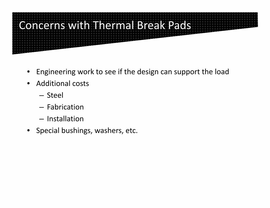
Concerns with Thermal Break Pads
• Engineering work to see if the design can support the load• Additional costs
– Steel– Fabrication– Installation
• Special bushings, washers, etc.

Aerogel Coatings
• Not a physical break in the steel, but acts as one without the design headaches.
• Coat 12”‐18” inboard, width of wall, and 12”‐18” outboard– Shifts the point of
condensation to outside of the building envelope

How Does a Coating Work?
• Superior thermal conductivity– 35 mW/mK compared to 260 mW/mK (or more) for thermal break pads.
• Changes surface temperature enough that moisture does not condense even without a physical break in the beam.

Think of a Blacksmith
• Steel losing heat to its surroundings by convection.– This is why he is able to hold the steel.
• If an aerogel coating (red bar) was applied, then he could not hold the end, as it reduces this convective heat loss.

Thermal Test Study—Background
• Simulate steel beams in the winter– Half in freezer and other half ambient– 4’ long steel beams
• Comparing Aerogel insulation coating to a structural thermal break (Thermal Break Pads).
• Evaluate surface temperature of steel using both materials compared to bare beam.

Test Conditions
Freezer Temp: ‐10°F Ambient Temp: 65°F
Bare Beam Thermal Break Pad
Aerogel Coating Outboard
Aerogel Coating Inboard

Sweating Bare Steel (control) Thermal Break Pad

Thermal Break Pad
• Sweating 8” up the warm side
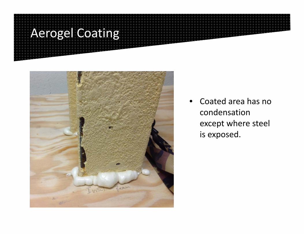
• Coated area has no condensation except where steel is exposed.
Aerogel Coating

41.8°F 44.5°F 54.9°F 56.3°F
Surface temperatures recorded 0.5” up the warm side.
Results in IR

Bare Beam with Coating Test Patch
Dramatic impact on the surface temperature!
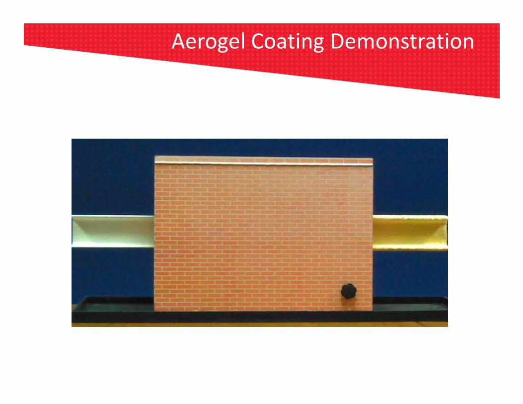
Aerogel Coating Demonstration
Aerogel Coating Demonstration
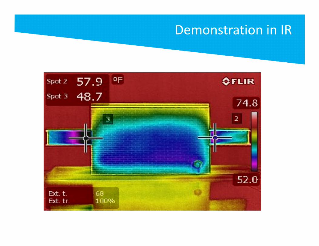
Demo in IR
Demonstration in IR

Aerogel Coating Advantages
• Shop or field application• New construction or retrofit• Easy application
– No need to topcoat– No additional engineering work as needed for physical thermal breaks

Summary
• The low thermal conductivity of aerogel coatings makes them an attractive option for a wide range of applications– Work great at raising the surface temperature and reducing condensation
• Concept applies to mitigating Thermal Bridging as well

Presenter Contact Information
Mr. Andy Hoffman Product Manager – Insulation & Specialty Products Tnemec Company, Inc. 6800 Corporate Drive, Kansas City, MO 64120 Phone: (816) 326‐4242Email: [email protected]

Thank You for Participating in Today’s presentation.
QUESTIONS?