report documentation page form approved 875 n … · final performance 3. dates covered ......
TRANSCRIPT

Standard Form 298 (Rev. 8-98) Prescribed by ANSI-Std Z39-18
REPORT DOCUMENTATION PAGE Form Approved OMB No. 0704-0188
Public reporting burden for this collection of information is estimated to average 1 hour per response, including the time for reviewing instructions, searching data sources, gathering and maintaining the data needed, and completing and reviewing the collection of information. Send comments regarding this burden estimate or any other aspect of this collection of information, including suggestions for reducing this burden to Washington Headquarters Service, Directorate for Information Operations and Reports, 1215 Jefferson Davis Highway, Suite 1204, Arlington, VA 22202-4302, and to the Office of Management and Budget, Paperwork Reduction Project (0704-0188) Washington, DC 20503.
PLEASE DO NOT RETURN YOUR FORM TO THE ABOVE ADDRESS. 1. REPORT DATE (DD-MM-YYYY) 11/3/11
2. REPORT TYPE Final Performance
3. DATES COVERED (From - To) 04/01/08-08/31/11
4. TITLE AND SUBTITLE 'Plastic' Electronics and Optoelectronics: New Science and Technology from Soluble Semiconducting Polymers
5a. CONTRACT NUMBER
5b. GRANT NUMBER FA9550-08-1-0248
5c. PROGRAM ELEMENT NUMBER
6. AUTHOR(S) Dr. Alan J. Heeger, Dr. Guillermo C. Bazan
5d. PROJECT NUMBER
5e. TASK NUMBER
5f. WORK UNIT NUMBER
7. PERFORMING ORGANIZATION NAME(S) AND ADDRESS(ES) Center for Polymers and Organic Solids University of California Santa Barbara, CA 93106-5090
8. PERFORMING ORGANIZATION REPORT NUMBER
9. SPONSORING/MONITORING AGENCY NAME(S) AND ADDRESS(ES) Air Force Office of Scientific Research
10. SPONSOR/MONITOR'S ACRONYM(S) AFOSR
11. SPONSORING/MONITORING AGENCY REPORT NUMBER
12. DISTRIBUTION AVAILABILITY STATEMENT Approved for public release; distribution is unlimited.
13. SUPPLEMENTARY NOTES None
14. ABSTRACT Bulk heterojunction (BHJ) solar cells were invented at UC Santa Barbara after the fundamental discovery of photoinduced ultrafast electron transfer from conjugated polymers to fullerenes. Many groups in the U.S., Europe and Asia are now making important contributions. Nevertheless, the UCSB group remains one of the leaders in the field. The high charge separation efficiency, the reduced fabrication costs associated with solution processing (printing and coating) and the implementation of this robust self-assembled technology on flexible substrates make “plastic” solar cells a compelling option for tomorrow’s photovoltaics. 15. SUBJECT TERMS
16. SECURITY CLASSIFICATION OF: 17. LIMITATION OF ABSTRACT
18. NUMBER OF PAGES
19a. NAME OF RESPONSIBLE PERSON Dr. Alan Heeger, Professor
a. REPORT
b. ABSTRACT
c. THIS PAGE
19b. TELEPONE NUMBER (Include area code)
805-893-3184
AFRL-OSR-VA-TR-2012-0939
875 N Randolph St
Arlington, VA 22203
Attn: Dr. Charles Lee

Final Technical Report
‘Plastic’ Optoelectronics: Injection Lasers Fabricated from Soluble Semiconducting
Polymers and
Bulk Heterojunction Solar Cells Fabricated from Soluble Semiconducting Polymers
Grant number: AFOSR FA9550-08-1-0248
Dr. Charle Lee, Program Manager 801 N. Randolph Street, Room 732
Arlington, VA 22203
Center for Polymers and Organic Solids University of California, Santa Barbara
Santa Barbara, CA 93106
Principal Investigators: Professor Alan J. Heeger Phone: (805) 893-3184 Mobile phone: (805) 570-9053 Fax: (805) 893-4755 E-mail: [email protected] Physics Department and Materials Department (joint appointment) Professor Guillermo C. Bazan Phone: (805) 893-5538 Fax: (805) 893-4755 E-mail: [email protected] Chemistry Department and Materials Department (joint appointment)

I. Introduction
Bulk hetetrojunction (BHJ) solar cells were invented at UC Santa Barbara after the fundamental discovery of photoinduced ultrafast electron transfer from conjugated polymers to fullerenes. Many groups in the U.S., Europe and Asia are now making important contributions. Nevertheless, the UCSB group remains one of the leaders in the field. Recent accomplishments in our group at UCSB of special importance include the following:
• Demonstration of PCDTBT:PC70BM with power conversion efficiency (PCE) of 6.5%,
PCE = 17% for monochromatic light within the absorption spectrum and internal quantum efficiency approaching 100%. This paper is one on the most highly cited papers in all of science since it appeared in print a little over a year ago. Even higher efficiencies have been reported since by other groups, but our Nature Photonics paper showed the way.
• The discovery of the utility of a class of processing additives (e.g. dithiol-alkanes, di-iodo
alkanes, chloro-naphthalene etc) enables optimization of the morphology. • The development of Phase Contrast TEM for morphology studies. The use of Phase
Contrast TEM combined with the ability to cut thin cross-sections enable direct imaging of the cross-sectional morphology that is critical to the collection of photogenerated carriers at the electrodes.
• The introduction of low band gap polymers and the discovery and creation of hybrid solar
cells in which a sol-gel processed TiOx layer serves multiple functions, including an increase in lifetime by a factor of 100!
• Complete analysis of recombination process in P3HT:PCBM and PCDTBT:PC70BM and the identification of the origin of the “mysterious” loss of open circuit voltage to values approx 0.3 V less that the energy difference between the LUMO of the acceptor and the HOMO pf the donor.
The high charge separation efficiency, the reduced fabrication costs associated with solution processing (printing and coating) and the implementation of this robust self-assembled technology on flexible substrates make “plastic” solar cells a compelling option for tomorrow’s photovoltaics.
Power Conversion Efficiency: Projected Values
Dennler, Scharber and Brabec (Adv. Mater 21, 1323, 2009) analyzed the power conversion efficiency that can be expected from BHJ solar cells.
Fig. 1 shows the PCE as a function of the bandgap (wavelength in nm) of the semiconducting polymer with several assumptions (for example, FF = 70%, EQE = 90% CT loss = 0.25 V). Based upon current understanding, the middle curve is believed to be closest to reality
• FF = 70% --- demonstrated by several research groups • EQE = 90% --- presently limited by combination of morphology and recombination;

EQE values > 60% have been demonstrated • CT loss ≤ 0.25 V --- demonstrated and understood in recent recombination studies at
UCSB.
The primary cause of the decrease in Voc is from the temperature dependence shown in Fig. 2. The “accepted value”, Voc=ELUMO(acceptor) – EHOMO(donor) is true only at T = 0 K. At finite T, the quasi-Fermi levels move away from ELUMO(acceptor) and EHOMO(donor) and into the gap (Fermi statistics; see Section C of Proposed Research):
0 100 200 300 4000.5
0.6
0.7
0.8
0.9
1.0
1.1
1.2
1.3
1.4
Vo
c (V
)
Temperature (K)
Thus, the origin of the loss in Voc has been identified with magnitude approximately 0.3 eV. This confirms that the middle curve in Fig. 1 utilizes the correct assumptions.
2ln
1
c
heBPolymerHOMO
FullereneLUMOoc N
nn
e
TkEE
eV
Figure 1
Figure 2 Open circuit voltage as a function of temperature (at various levels of brightness) for PCDTBT:PC70BM;
UCSB group (In Press)

Conclusion: Plastic BHJ Solar Cells can be a 15 - 20% technology
The blue star on Fig. 1, shows where the field is today; PCE = 7 – 8 % in response to
AM1.5 solar radiation: below --- but not far below --- the projected curve. But of course, the absorption band of PCDTBT (or any of the polymers currently being used in BHJ cells) does not extend far enough into the IR. As a result, approximately half the solar radiation is not harvested by PCDTBT:PC70BM.
The gold star in Fig. 1, represents the 17% efficiency obtained with monochromatic green light at wavelength within the absorption band. The implication is clear: We are basically “on track”.
The gold arrow in Fig. 1 shows the benefit of extending the absorption band out to approx 900 nm (keeping the FF and EQE high). By doing so, we will be able to demonstrate PCE = 15%. Note that one can reduce the gap without reducing the open circuit voltage: For the 17% PCE, the green light is harvested at 2.5 eV, but the energy is taken out of the solar cell after carrier relaxation to the band edges; i.e. at the open circuit value of 0.88 V. Thus, the argument expressed by the gold arrow on Fig. 1 is sound.
The basic device physics of BHJ solar cells is understood: It is essentially the same as that in inorganic solar cells. By fine-tuning the energy gap and the HOMO of the semiconducting polymer, one can achieve Voc values close to the maximum value possible; i.e. eVoc equal to the band gap. With FF = 70%, EQE = 70% and band gap approx 900 - 1000 nm, the BHJ technology can reach 15%. With EQE increased to 90% through morphology control even higher PCE values can be anticipated.
II. SPECIFIC ACCOMPLISHMENTS A. Optimization of the Bulk Heterojunction (BHJ) morphology using specifically
identified processing additives; Monitor the BHJ nano-structure with Phase Contrast TEM
Figure 3 shows that major improvements in PCE can be achieved with the use of processing additives:
OCH3O OCH3O
Figure 3 Factor of 2 improvement obtained by using octane-dithiol as processing additive Peet et al., Nature Mater. 2007, 6, 297-500

Although it is generally agreed that the origin of this major improvement in cell performance is the result of improved morphology, this has not been demonstrated by detailed studies of the morphology.
Phase Contrast TEM E-beam undergoes many small angle
deflections proportional to the density of carbon nuclei
PCBM has higher density of carbon nuclei
E-beam velocity is slower in PCBM than in Polymer
Result: Phase Contrast
Morphology of the BHJ Materials
The first example of the use of Phase Contrast TEM to monitor the change in nano-morphology that results from the use of a processing additive is shown in Figure 4.
Si-PDTBT:PC70BM 1:1 in CB (without CN)
Top-down TEMDef=-25μm
Cross-section TEMDef=-25μm
Si-PDTBT:PC70BM 1:1 in CB with 4 % CN
Top-down TEMDef=-25μm
Cross-section TEMDef=-25μm
Figure 4 Upper: Top down and cross-sectional images of Si-PDTBT:PC70BM 1:1 in CB (without chloro-naphthalene) Lower: Top down and cross-sectional images of Si-PDTBT:PC70BM 1:1 in CB (processed with 4% chloro-naphthalene) Phase Contrast defocus: 25 microns This is but one example. As part of the Proposed Research, we will carry out similar Phase Contrast TEM studies using alkane dithiols and di-iodo-octane as processing additives (see J.K. Lee et al., JACS, 130, 3619, 2008).
Using Phase Contrast TEM, with optimum defocus, we have sufficient
contrast to distinguish between “good” and “bad” morphologies.

Moreover, as shown below in Figure 5, Phase Contrast TEM with 25 m defocus can unambiguously distinguish between “good” and “bad” morphologies.
1E-3 0.01 0.1 1
0.01
0.1
1
0.039
PSD
(a.
u.)
frequency (nm-1)
0 10 20 30 40 50 60
-0.2
0.0
0.2
0.4
0.6
0.8
1.0
A
CR
(a.
u.)
~ 25 nm
distance (nm)
(b) Power Spectral Density (c) Autocorrelation Function
(a) Cross-Sectional TEM image for P3HT:PCBM BHJ film post-annealed at 150℃
_____________________________________________________________________________
Cross-sectional TEM Image of the PCDTBT:PC70BM BHJ --- 6.5% PCE
100 nm
in the Lateral Direction
in the Vertical Direction
0.01 0.1 1
0.1
1
10
PS
D (
A.U
.)
Spatial Frequency (nm-1)
0.061
0.063nm1
≈ 15.8 nm
0 10 20 30 40 50 60 70-0.4
-0.2
0.0
0.2
0.4
0.6
0.8
1.0
AC
R (
A.U
.)
Distance (nm)
15.6 nm
0 10 20 30 40 50 60 70
0.0
0.2
0.4
0.6
0.8
1.0
AC
R (
A.U
.)
Distance (nm)
0.01 0.1 1
0.01
0.1
1
PS
D (
A.U
.)
Spatial Frequency (nm-1)
SS
N
C8H17 C8H17
n
N NSa
OMe
O
Figure 5a Example of a “good” morphology: the column-like quasi-periodic nano-structure of a cross-section of P3HT:PCBM (annealed at 150C). Note the nearly straight-line paths for carriers to reach the electrodes. See Moon, J. S.; Lee, J. K.; Cho, S.; Byun, J.; Heeger, A. J., Nano. Lett. 9, 230..
Figure 5b Example of a “bad” morphology--- the horizontally striated nano-structure of a cross-section of PCDTBT:PC70BM. No indication of quasi-periodic nano-structure in the lateral direction. Note the long tortuous path for carriers to reach the electrodes.

Despite the higher PCE of PCDTBT:PC70BM, the nano-structure is far from optimized. When we are able to convert to a “column-like”nano-structure (like that of P3HT:PCBM above), the PCE will improve accordingly. B. Demonstrated the importance of minimization of carrier loss thru recombination prior
to collection at the electrodes: Recombination processes were studied using Time Resolved Photoconductivity on operating solar cells: The evolution from sweep-out near short circuit to recombination near open circuit is directly observable.
The time dynamics of the operation of the BHJ solar cell are summarized in Fig. 6.
• Photo-induced charge transfer takes place in the sub-picosecond time scale.
• At longer times, the mobile carriers are swept out by the internal voltage (built-in electric field) in competition with recombination during the sweep-out transit time.
Note that not all the absorbed photons lead to mobile carriers; some of the initially photogenerated carriers fall into interfacial traps or form bound interfacial charge transfer excitons (see Fig 6), and some carriers are trapped in localized states deep within the π-band tail of the donor polymer or the LUMO band tail of the acceptor.
The characteristic sweep-out time, sw, is given by the thickness (d) divided by the drift velocity of the mobile carriers, μE, where μ is the average carrier mobility, E = V/d, and V is the internal voltage (|V| ~ Voc at short circuit, and V → 0 as Voc → |V|):
sw = d2/2V. (B1)
The factor of 2 arises because the carrier generation is uniform throughout the film; on average, mobile carriers must travel through only approximately half the film thickness.
The cell photocurrent IP(V), can be expressed as follows:
GVePVIVI CDP )()()( (B2)
Mobile carriers sweep out by the internal
voltage (built-in electric field)
Ground state
Interfacial traps and
Interfacial excitons
Excited state and
charge transfer
hν
Recombination
t < 200 fs
t < 200 fs
Figure 6 Time dynamics of the operation of the BHJ solar cell

where ID(V) is the dark current, e is the electron charge, and V is the externally applied bias voltage. PC(V) is the normalized photocurrent and is equivalent to the bias dependent probability of collection of carriers at the electrodes prior to recombination, while G is the effective generation rate, including any loss resulting from optical excitations that do not reach the charge separating interface. PC(V) approaches unity in reverse bias, corresponding to complete collection of the generated charge, and decreases in forward bias as the internal field decreases and recombination becomes, therefore, increasingly important.
In an operating solar cell, the internal voltage (Vint) is the difference between the built-in voltage (Vbi) across the BHJ layer and the applied voltage (V); Vint = Vbi - V. The second term in Eq. 1 goes to zero at V = Vbi; the total current is zero at Voc , the voltage at which the photogenerated current cancels the dark current. Voc is slightly less than Vbi (see Eq. 1). At short circuit, the internal voltage is equal to the built-voltage, |Vint | |Vbi| |Voc|. As the external applied voltage approaches Voc, however, |Vint| → 0. Under steady state irradiation at light intensities equivalent to 1 sun, the density of mobile holes (p) in the polymer domains and mobile electrons (n) in the fullerene domains within the BHJ material can be estimated from the short circuit current using Jsc neμVint/d where d is the thickness of the BHJ charge-generating film; p = n ~ 1015 -1016 cm-3.
B1. Detailed analysis of the Transient Decay of the Photocurrent in Operating BHJ Solar Cells
To directly monitor the competition between sweep-out and recombination, we have carried out measurements of transient photoconductivity in operating solar cells. The following discussion provides the theoretical analysis of the experiment.
When a charge q moves a small distance dx across a parallel plate capacitor of thickness D, the change in charge induced on the electrodes is
Q=q dx/D (B3) The rate of change of charge is the current (the displacement current), I I = (q/D) dx/dt = qv/D = qE/D (B4) Under illumination, there is an initial charge density distribution through the sample N(x). The current at time t is the integral of Eq. 4 over the distribution N(x). After time t, however, all the charges have moved by a distance Et, so the integral starts from this position, hence
dxD
EEtxNtI
D
Et
)()( (B5)
Assuming that the distribution is uniform across the thickness (the film is optically “thin”), N(x) = N0 and
D
EtENEtD
D
ENdx
D
ENtI o
D
Et
1)( 00 (B6)
For optically ”thick” films, where N(x) is not constant, one could insert the thickness dependence into Eq. B5 and integrate.
Because of recombination, the carrier density, N0 decays with time and the constant value has to be replaced by N0 exp(-t/R),
D
EttENtI R
1)/exp()( 0 (B7)

The contributions to the current from the transport of electrons and holes add (opposite charges go in opposite directions), so the total current is the sum of the current given by Eq. B7 with values for the two carriers.
heidVttEeNVtI iRiiPi ,);/1()/exp(),( 20 (B8)
The limiting cases of Eq. B7 are the following: In the transit time limit, IP(t,V) decreases linearly with time because absorption is throughout the thickness (unlike the usual time-of-flight case where the carriers start at one side of the sample). The charge collection is the integral of Eq. B8 up to the transit time and is given by the sum of the electron and hole contributions,
Fig. 7 shows the evolution from sweep out (at or near short circuit conditions where the
internal built-in voltage is large) to recombination decay near open circuit (where the internal voltage is compensated by the external applied voltage). The data shown in Fig. 7 were obtained from solar cells fabricated from P3HT/PCBM. The BHJ layer within the cell was about 100 nm thick. The excitation source was a nitrogen pumped dye laser emitting a pulse of <10ns duration at ~520nm.
0 2 4 6 810
-3
10-2
10-1
100
Time (s)
J / V
int (
m
-1 c
m-2
)
0.7V0.6V0.4V0.2V0.0V-0.5V-1.0V-1.5V
Figure 7 The evolution from sweep out (at short circuit) to recombination at open circuit is demonstrated through transient photoconductivity measurements carried out at different external applied voltages for a PCDTBT:PC70BM solar cell at room temperature. The conductance (Iph/Vint) is plotted vs time following the light pulse where Vint = VBI – V. The fact that all curves start at the same conductance value verifies the concept of well-defined values for Vint = VBI – V in the BHJ solar cell --- a remarkable result given the complexity of the self-assembled nano-structure.
Transit time limit near short circuit )/1(),(; 2
1101 dVtEeNVtItt PTR (B9)
Recombination decay limit near open circuit
)/exp(),(; 1101 RPTR tEeNVtIt ) (B10)

In reverse bias the current transient is complete (reduced by more than an order of magnitude in a fraction of a μs. Near open circuit, however, the current transient continues beyond 10s. Thus, in very general terms, the sweep-out at short circuit is a order of magnitude faster than the recombination time, consistent with the high internal quantum efficiency of PCDTBT. The evolution from sweep out (at short circuit or in reverse bias where the internal voltage is large) to recombination decay near open circuit (where the internal voltage is compensated by the external applied voltage) is evident in the data. C. Determine the recombination mechanism(s) in BHJ solar cells with the goal of
increasing the short circuit current, the Fill Factor (FF) and the open circuit voltage.
The power conversion efficiency (PCE) of a solar cell is given by the well-known relation PCE = JscVocFF/Pin where Jsc is the short circuit current, Voc is the open circuit voltage, FF is the Fill Factor and Pin is the incident solar power. Since recombination results in loss of photogenerated charge carriers, acquiring an understanding of the mechanisms governing recombination is critical for increasing Jsc and FF and thereby increasing the solar cell performance. Using a detailed balance approach, Shockley and Queisser1 showed that the open circuit voltage of a solar cell is maximum when the photogenerated charges recombine only radiatively. For bulk heterojunction (BHJ) solar cells made from blends of semiconducting polymers and fullerenes, the recombination mechanisms are mostly non-radiative.2Thus, overcoming such recombination can, in addition, increase the open circuit voltage.
The recombination mechanisms in polymer BHJ solar cells are, however, far from clear. For P3HT:PCBM3 cells, contradictory explanations based both on geminate (monomolecular) and non-geminate (bimolecular) recombination have been proposed, but have met with only limited success in explaining the current-voltage characteristics. Recently, for PCDTBT:PC71BM solar cells with power conversion efficiency greater than 6%, Shockley-Read-Hall recombination at interfacial traps7 was proposed as the dominant mechanism. Moreover, transient photoconductivity measurements carried out on functional and operating solar cells comprising P3HT:PC60BM and PCDTBT:PC71BM established that geminate recombination plays a smaller role than previously expected.
Is recombination in polymer solar cells monomolecular, bimolecular, or a combination of the two? What is the effect of applied voltage on the recombination kinetics? We arrive at answers to these important questions by measuring the current-voltage characteristics over a range of different illumination intensities and temperatures using polymer BHJ solar cells made from three different semiconducting polymers (PCDTBT, P3HT, KP3,12) and two different fullerenes (PC60BM and PC71BM3). Our results reveal that the kinetics of recombination for polymer BHJ solar cells depend on the external voltage applied to the device: The current density versus voltage (J-V) curves are limited by monomolecular recombination from the short circuit condition to the maximum power point and evolve to bimolecular recombination in the range of voltages from the maximum power point to the open circuit condition. Furthermore, we find a universal dependence of the open circuit voltage (Voc) for polymer BHJ solar cells on incident light intensity; δVoc = (kBT/e) ln(I), where I is the incident light intensity, kB is the Boltzmann constant, T is the absolute temperature and e is the electron charge. The slope of δVoc vs ln(I) demonstrates that bimolecular recombination dominates for applied voltages near Voc. For comparison, we also probe the incident light intensity dependence and temperature dependence of the current-voltage characteristics of a p-i-n junction hydrogenated amorphous silicon (a-Si) solar cell, where the recombination has been ascribed to trap sites at the p/i and i/n interfaces.
To probe the kinetics of recombination, solar cells were fabricated with the following compositions: PCDTBT:PC71BM (1:4), P3HT:PC60BM (1:0.7), and KP:PC60BM (1:3); details are

provided in the Supplementary Information (S1). In addition, measurements were carried out on commercial amorphous silicon (a-Si) solar cell samples obtained from Contrel Technology Co. Ltd. (Taiwan). J–V characteristics were collected while illuminating the solar cells over a range of intensities from 0.4 mW/cm2 to 100 mW/cm2. The spectrum of the incident light was adjusted for every value of intensity to closely mimic the AM1.5G spectrum. C1. Intensity Dependence of the Current-Voltage Curves
Fig. 8(a) shows the current-voltage characteristics of the PCDTBT:PC71BM solar cell for incident light intensities ranging from 0.4 to 100 mW/cm2. The total current density flowing through the solar cell is a function of the incident light intensity (I) and the applied voltage (V), and is given by the sum of the dark current (Jdark) and photogenerated current (Jphoto):
VJVIJVIJ darkphoto ,,
(C1) The photocurrent in Eq. 1 can be written as Jphoto(I,V) = G(I)Pc(I,V), where G(I) is the photon flux absorbed by the solar cell and PC(I,V) is the charge collection probability. As is evident from Fig. 8(a), the current becomes independent of the applied voltage around -0.5 volts (reverse bias). Hence, assuming a reverse saturation current such that G(I) = Jphoto(V = -0.5 volts):
VIJ
VIJVIP
photo
photoC 5.0,
,,
.
(C2) We note that for PCDTBT: PC71BM, the internal quantum efficiency approaches 100% so that PC is known to approach unity at short circuit.10
Fig. 8(b) shows the charge collection probability (or the normalized photocurrent for PCDTBT:PC71BM solar cell) as a function of applied voltage for all the intensity dependent curves shown in Fig. 8(a). The data collapse onto a universal curve in the range of applied voltages from -0.5 volts to approximately 0.7V, or close to the maximum power point. Hence, PC(I, Vapplied) ≈ PC(V), independent of intensity, I, from short circuit to Vapplied > VMPP where VMPP
is the voltage at the maximum power point. Given the linear variation of J(-0.5V) with incident light intensity shown in the inset of
Fig. 8(b) and the collapsed collection probability curve in the range of voltages from -0.5 to 0.7 volts, we conclude that the photocurrent in this voltage range is linearly dependent on intensity. Therefore in this regime, the recombination is dominated by a monomolecular mechanism.

Fig. 9(a) shows the linear dependence of the short circuit current of the P3HT:PC60BM,
KP:PC60BM, and a-Si (p-i-n junction) solar cells on incident light intensity; the dominant recombination mechanism at short circuit is monomolecular. The collection probability for the different BHJ solar cells is plotted as a function of voltage and intensity in Figs. 9(b)-(d). Again, the collection probability for incident light intensities that vary over an order of magnitude collapse in the voltage range from -0.5 volts to near the maximum power point. This collapse indicates that throughout this voltage range, the photocurrent increases linearly with intensity and implies intensity-independent recombination. Hence, for all these BHJ solar cells, monomolecular recombination dominates for the range of applied voltages from -0.5 volts to near the maximum power point.
Beyond the maximum power point, however, the charge collection probability becomes dependent on the incident light intensity; see Fig. 8(b) and Figs. 9(b)-(d). The spread in the collection probability curves for various incident light intensities is most evident at the open circuit voltage, the externally applied voltage at which the total current is zero. As we show
Figure 8: (a) Current-voltage characteristics of PCDTBT:PC71BM solar cells as a function of incident light intensity; (b) Charge collection probability: Photocurrents measured for the various intensities in (a) have been normalized with the photocurrent at -0.5 volts. The two ovals highlight voltage ranges where monomolecular and bimolecular recombination kinetics are dominant. Inset: The magnitude of current density at -0.5 volts plotted against incident light intensity.
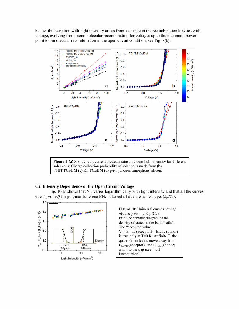
below, this variation with light intensity arises from a change in the recombination kinetics with voltage, evolving from monomolecular recombination for voltages up to the maximum power point to bimolecular recombination in the open circuit condition; see Fig. 8(b).
C2. Intensity Dependence of the Open Circuit Voltage
Fig. 10(a) shows that Voc varies logarithmically with light intensity and that all the curves of Voc vs ln(I) for polymer:fullerene BHJ solar cells have the same slope, (kBT/e).
Figure 9:(a) Short circuit current plotted against incident light intensity for different solar cells; Charge collection probability of solar cells made from (b) P3HT:PC60BM (c) KP:PC60BM (d) p-i-n junction amorphous silicon.
Figure 10: Universal curve showing δVoc as given by Eq. (C9). Inset: Schematic diagram of the density of states in the band “tails”. The “accepted value”, Voc=ELUMO(acceptor) – EHOMO(donor) is true only at T=0 K. At finite T, the quasi-Fermi levels move away from ELUMO(acceptor) and EHOMO(donor) and into the gap (see Fig 2, Introduction).

C3. Analysis of the Cross-over from Monomolecular to Bimolecular Recombination The internal voltage within the device, given by the difference Vbi – V, drives the carriers
to the electrodes and determines the timescale for the sweep-out of carriers, s w = d2 /2μ(Vb i-V) , where μ is the charge carrier mobility, d is the distance between the electrodes, and Vbi is the built-in potential. At a given voltage, competition between sweep out and recombination will determine the carrier density available for recombination within the device.
The increased carrier density with decreasing internal voltage (decreasing carrier sweep-out) causes the transition from monomolecular to bimolecular recombination kinetics. The charge recombination rate (R) at open circuit voltage can be written as a sum of two terms
2oc
r
ocococ n
nVGVR
(C3)
where r is the monomolecular recombination lifetime, noc is the charge carrier density within the device at open circuit, γ is the bimolecular recombination coefficient, and G is the rate of generation of electrons and holes. The ratio of the two terms summed in Eq. (C3) will determine the carrier density, or alternatively, the magnitude of the bimolecular recombination coefficient, at which the recombination mechanism transitions from monomolecular to bimolecular kinetics; this cross-over is given by γne > 1/τr.
The balance of charge carriers within the device at any voltage is determined by 1
e
J
x G R. (C4)
At short circuit, the current is dominated by drift and sweep-out, i.e., J nsceVbi/d. Hence, in the absence of recombination (1/e) dJ/dx ≈ G in Eq. (C4), and the short circuit carrier density is given by:
nsc G s (C5) where s = d2/2Vbi is the charge sweep out time at short circuit, d is the BHJ thickness, is the average carrier mobility and Vbi is the built-in potential.
At open circuit, dJ/dx = 0 and Eq. (C4) reduces to G = R, where R is a sum of monomolecular and bimolecular recombination terms. From Eqs. (C3) and (C5), we obtain:
oc
roc
s
sc nnn
1
(C6) Since bimolecular recombination dominates at open circuit, γnoc > 1/τr, implying that noc / nsc > r/s. The ratio r/s 10, as obtained from transient photoconductivity measurements on operating solar cells.11 However, the precise agreement of the slope of Voc vs ln(I) with (kBT/e) implies that noc >> 1/r. Thus, we estimate that noc is at least a factor of 100 larger than nsc.
Assuming that the carriers are uniformly distributed through the bulk of the cell, Jsc is determined by the drift current, Jsc =Jdrift = enscμE. One can therefore use Jsc to estimate the carrier density in the device under steady state conditions (AM1.5 solar spectrum). For PCDTBT:PC71BM solar cells10, Jsc = 11 mA/cm2. Thus, nsc 1015 cm-3 (assuming μ =10-3 cm2/V-s)14-15. Using r 10-6 s obtained directly from transient photoconductivity measurements carried out on operating solar cells11 and noc/nsc > 100, we find 10- 1 1-10- 1 2 cm3/s. Note that the inferred value for is significantly smaller than the magnitude obtained from the Langevin expression16-17, = e/, possibly because the BHJ phase separation assures that the electrons (in the fullerene domains) are spatially separated from the holes (in the semiconducting polymer).
C4. Effect of Recombination on the Open Circuit Voltage

The recombination mechanism governs the extent to which the incident light intensity modulates the open circuit voltage. When a polymer solar cell is under illumination at open circuit, the applied voltage equals the difference between the quasi-Fermi levels of polymer and fullerene. From this observation, we obtain the following expression for the open circuit voltage (see discussion in the Introduction Section):
2ln
1
c
hePolymerHOMO
FullereneLUMOoc N
nn
e
kTEE
eV (C7)
where ne and nh are the electron and hole densities in the fullerene and polymer domains at open circuit. To leading order, the interfacial band offset associated with the heterojunction (the difference between the HOMO level of polymer and the LUMO level of the fullerene) determines the Voc of polymer BHJ solar cells. The energy shift, , in the first term of Eq. C7 originates from disorder within the solution cast and phase separated polymer and fullerene regions. As sketched in the inset to Fig. 10, due to the disorder, the density of states in both phases is expected to have a “tail” with localized energy levels higher/lower than the polymer HOMO/fullerene LUMO levels. As a result, the first term in Eq. 7 is reduced by 0.1-0.3 eV Under AM1.5 solar illumination, the quasi-Fermi levels within the polymer and fullerene will split from a common value in the dark and re-set, respectively, in the band tails just above the polymer HOMO energy and just below the fullerene LUMO energy level. The validity of the first term in Eq. 7 has been verified for a number of polymer:fullerene BHJ systems. The photo-generated carrier densities determine the quasi-Fermi energies inside the band “tails” and, consequently, increase Voc toward the intrinsic value expected from the heterojunction interfacial band off-set; i.e. toward
PolymerHOMO
FullereneLUMOoc EE
eV
1.
In the limit where bimolecular recombination is dominant, nenh = (noc)2 = G/, which
when substituted into Eq. C7 results in δVoc = (kBT/e) ln(I) + constant, where I is the incident light intensity. If monomolecular recombination were the dominant mechanism over the full range of applied voltages from short circuit to open circuit, the “collapsed” J-V curve would look qualitatively the same as that shown in Fig. 8(b). However, for monomolecular recombination ne
and nh (at open circuit) would each be proportional to the intensity, and the slope of δVoc vs ln(I) would be 2(kBT/e).
In Fig. 10, we plot the light intensity dependence of the open circuit voltage for all the polymer:fullerene BHJ solar cells described in Fig. 8 and Fig. 9. The data demonstrate that the slope is of δVoc vs ln(I) is equal to kBT/e within the measurement error. In addition, we include in Fig. 3(a) the light intensity dependence of Voc as reported by others obtained using different semiconducting polymers in the BHJ material. We find that for all these different polymer-fullerene systems, the slope remains equal to kBT/e. This universality highlights the generality of bimolecular recombination kinetics at open circuit in polymer BHJ solar cells.
The temperature dependence of Voc for PCDTBT:PC71BM solar cells is plotted in Fig. 1 in the Introduction. Fig. 1 shows the linear dependence of Voc with temperature at various light intensities. The dashed lines, predicted by Eq. C7, fit well to the data and predict an interfacial
band offset, to within the limit of the -shift, eV25.11
0 PolymerHOMO
FullereneLUMOoc EE
eKTV .
This result agrees well with cyclic voltammetry measurements of the HOMO energy of PCDTBT23 (-5.5 eV) and of the LUMO energy of PCBM24 (-4.3 eV), such that interfacial band offset is measured to be 1.2 eV. Fig. 4(b) provides an independent measure of the electronic structure obtained in situ, with an accuracy of 0.05 eV. Finally, the temperature dependence of the Voc is the result of thermal excitations. At finite temperatures the qusi-Fermi-levels move away from the PCBM LUMO and from the polymer HOMO and drop into the gap. This is quite

simply the result of the Fermi statistics. The effect is profound, the “missing” loss in Voc is now understood. Publications resulting from the three-year AFOSR Program: List of the Publications during Sept 1, 2007 – Aug 31, 2008 Supported by AFOSR:
1. Processing Additives for Improved Efficiency from Bulk Heterojunction Solar Cells, Jae Kwan Lee,Wan Li Ma,Christoph J. Brabec, Jonathan Yuen, Ji Sun Moon, Jin Young Kim, Kwanghee Lee, Guillermo C. Bazan, and Alan J. Heeger, J Amer. Chem. Soc. 130, 3619, 2008.
2. Titanium-oxide Films as Multifunctional Components in Bulk Heterojunction “Plastic” Solar Cells, Kwanghee Lee, Jin Young Kim and Alan J. Heeger; Book Chapter in “Organic Photovoltaics: Materials, Device Physics and Manufacturing Techniques, Edited by C. Brabec, V. Dyankonov and U. Scherf (Chapter 9).
3. Functionalized Methanofullerenes Used as n-type Materials in Bulk Heterojunction Polymer Solar Cells and infield Effect transistors, C. Yang, J.Y. Kim, J.K. Lee, A.J. Heeger and F. Wudl, JACS, 130, 644, 2008.
4. Efficacy of TiOx optical spacer in bulk-heterojunction solar cells processed with 1,8-octanedithiol, J.K. Lww, N. E. Coates, S. Cho, N. S. Cho, D. Moses, G. C. Bazanand A.J. Heegeer Applied Physics Letters, 92, 243308, 2008.
5. High Performance light emitting transistors, E.B. Namdas, P. Ledochowitsch, J. Yuen, D.Moses and A.J. Heeger, Appl. Phys. Lett. 92, 183304, 2008.
6. Gate-controlled light emitting diodes, E.B. Namdas, J.S. Swensen, P. Ledochowitsch, J. Yuen, D. Moses and A.J. Heeger, Adv. Mater. 20, 1321, 2008.
7. Low threshold in polymer lasers on conductive substrates by Distributed Feedback Nanoimprinting: Progress toward electrically pumped plastic lasers, E.B. Namdas, M. Tong, P. Ledochowitsch, S. R. Mednick, J. D. Yuen, D. Moses and A. J. Heeger, Adv. Mater. (in press).
8. Nanostructure of the Interpenetrating Networks in Poly(3-hexylthiophene)/fullerene Bulk Heterojunction Materials: Implications for Charge Transport, W. Ma, A. Gopinathan, A. J. Heeger, Adv. Mater., 19, (21), 3656-3659, (2007).
List of the Publications during Sept 1, 2008 – Aug 31, 2009 Supported by AFOSR: 1. Bulk Heterojunction Materials made from poly(2,5-bis(3-alkylthiophen-2-yl)thieno[3,2-b]thiophene):
Ultrafast Electron Transfer and Carrier Recombination, I.-W. Hwang, J. Y. Kim, S. Cho, J. Yuen, N. Coates, K. Lee, D. Moses, M. Heeney, I. McCulloch, A. J. Heeger, J. Phys. Chem. C, 112 (21) 7853-7857 (2008).
2. Carrier generation and transport in bulk heterojunction films processed with 1,8-octanedithiol as a processing additive, I.-W. Hwang, S. Cho, J. Y. Kim, K. Lee, N. E. Coates, D. Moses, A. J. Heeger, J. Appl. Phys., 104 (3) 033706, (2008).
3. Low Thresholds in Polymer Lasers on Conductive Substrates by Distributed Feedback Nanoimprinting: Progress Toward Electrically Pumped Plastic Lasers, E. B. Namdas, M. Tong, P. Ledochowitsch, S. R. Mednick, J. D. Yuen, D. Moses, A. J. Heeger, Adv. Mater., 21, 799–802, (2009).
4. Bulk heterojunction solar cells with internal quantum efficiency approaching 100%, S. H. Park, A. Roy, S. Beaupre´, S. Cho, N. Coates, J. S. Moon, D. Moses, M. Leclerc, K. Lee, A. J. Heeger, Nature Photonics 3 297 (2009).
\ 6. Higher molecular weight leads to improved transport in a low-band gap semiconducting
polymer, Minghong Tong, Shinuk Cho, Bang-Yu Hsu, Daniel Moses Robert C. Coffin, Guillermo C. Bazan and Alan J. Heeger Adv. Mater. (submitted)

List of the Publications during Sept 1, 2009 – April 30, 2010 Supported by AFOSR:
1. Charge carrier photogeneration and decay dynamics in the poly(2,7-carbazole) copolymer PCDTBT and in bulk heterojunction composites with PC70BM, M. Tong, N. E. Coates, D. Moses, A. J. Heeger, S. Beaupré, M. Leclerc, Phys. Rev. B 81, 125210 (2010).
2. Organic light emitting complementary inverters, E. B. Namdas, I. D. W. Samuel, D. Shukla, D. M. Meyer, Y. Sun, B. B. Y. Hsu, D. Moses, A. J. Heeger, Appl. Phys. Lett. 96, 043304 (2010).
3. Conjugated polyelectrolytes for organic light emitting transistors, J. H. Seo, E. B. Namdas, A. Gutacker, A. J. Heeger, G. C. Bazan, Appl. Phys. Lett. 97, 043303 (2010).
4. Semiconducting polymers: the Third Generation, A. J. Heeger, Chem. Soc. Rev., 39, 2354–2371 (2010).
5. Higher Molecular Weight Leads to Improved Photoresponsivity, Charge Transport and Interfacial Ordering in a Narrow Bandgap Semiconducting Polymer, M. Tong, S. Cho, J. T. Rogers, K. Schmidt, B. B. Y. Hsu, D. Moses, R. C. Coffin, E. J. Kramer, G. C. Bazan, A. J. Heeger, Adv. Funct. Mater. 20, 3959–3965 (2010).
6. Increased open-circuit voltage in bulk-heterojunction solar cells using a C-60 derivative, H. Kim, J. Hwa Seo, E. Y. Park, T-D. Kim, K. Lee, K-S. Lee, S. Cho, A. J. Heeger, Appl. Phys. Lett. 97, 193309 (2010).
7. Inverted Polymer Solar Cells Integrated with a Low-Temperature-Annealed Sol-Gel-Derived ZnO Film as an Electron Transport Layer, Y. Sun, J. H. Seo, C. J. Takacs, J. Seifter, A. J. Heeger, Adv. Mater., 23, 1679–1683 (2011).
8. Efficient, Air-Stable Bulk Heterojunction Polymer Solar Cells Using MoOx as the Anode Interfacial Layer, Y. Sun, C. J. Takacs, S. R. Cowan, J. H. Seo, X. Gong, A. Roy, A. J. Heeger, Adv. Mater., 23, 2226–2230 (2011).

Personnel Supported: 1. PI and co-PI involved in the research project: 3 Professor Alan J. Heeger Professor Guillermo C. Bazan Dr. Daniel Moses 2. Number of Post Docs supported during the 3-year AFOSR project: 5 Yanming Sun Minghong Tong Jonathan Yuen Wei Lin Leong Huaping Li 3. Number of graduate students supported during the 3-year AFOSR project: 7 Ji Sun Moon Bang-Yu Hsu Jason Seifter Logan Garner Aidee Duarte Louis Perez Thomas Van Der Poll 4. Other researchers supported during the 3-year AFOSR project: 4 Ebinazar Namdas Hongmei Zhan Kwanghee Lee Huiping Wang