report lot 269, 1 cogla street, malaga wa
TRANSCRIPT

REPORT
Lot 269, 1 Cogla Street, Malaga WA Geotechnical Investigation Report
Submitted to:
City of Swan PO Box 196
MIDLAND WA 6936
Submitted by:
Golder Associates Pty Ltd
Level 3, 1 Havelock Street, West Perth, Western Australia 6005, Australia
+61 8 9213 7600
18113391-001-R-Rev0
February 2019

February 2019 18113391-001-R-Rev0
i
Distribution List Electronic Copy – City of Swan
Electronic Copy – Golder Associates Pty Ltd

February 2019 18113391-001-R-Rev0
ii
Table of Contents
1.0 INTRODUCTION ......................................................................................................................................... 1
2.0 OBJECTIVES .............................................................................................................................................. 1
3.0 GEOTECHNICAL FIELDWORK ................................................................................................................. 1
4.0 SITE CONDITIONS ..................................................................................................................................... 2
4.1 Surface Conditions ............................................................................................................................ 2
4.2 Regional Geology .............................................................................................................................. 3
4.3 Subsurface Conditions ...................................................................................................................... 3
4.4 Groundwater...................................................................................................................................... 3
5.0 LABORATORY TESTING .......................................................................................................................... 3
5.1 Geotechnical Results ........................................................................................................................ 3
6.0 GEOTECHNICAL DISCUSSION ................................................................................................................ 4
6.1 Preliminary Site Classification ........................................................................................................... 4
6.2 Site Preparation ................................................................................................................................ 4
6.3 Compaction ....................................................................................................................................... 4
6.4 Shallow Footings ............................................................................................................................... 5
6.5 Excavations ....................................................................................................................................... 6
6.6 Earthquake Design ............................................................................................................................ 6
6.6.1 Earthquake Site Subsoil Classification ......................................................................................... 6
6.7 Drainage ............................................................................................................................................ 6
6.7.1 Stormwater Disposal ..................................................................................................................... 6
6.8 Potential Geotechnical Risks ............................................................................................................ 7
6.8.1 Uncontrolled Fill ............................................................................................................................ 7
6.8.2 Excavation Stability and Proximity to Adjacent Buildings or Services .......................................... 7
6.8.3 Settlement ..................................................................................................................................... 7
6.8.4 Reduced Effectiveness of Soakwells ............................................................................................ 7
6.8.5 Acid Sulfate Soil ............................................................................................................................ 7
7.0 IMPORTANT INFOMATION ....................................................................................................................... 8

February 2019 18113391-001-R-Rev0
iii
TABLES
Table 1: Test Location Summary .......................................................................................................................... 2
Table 2: Summary of Geotechnical Laboratory Testing ....................................................................................... 3
Table 3: Allowable Bearing Pressure and Settlement Estimate Under Static Load ............................................. 5
FIGURES
Figure 1: Location Plan
Figure 2: Site Plan
APPENDICES
APPENDIX A Cone Penetration Test Reports
APPENDIX B Hand Auger Borehole Reports
APPENDIX C Geotechnical Laboratory Certificates
APPENDIX D Important Information

February 2019 18113391-001-R-Rev0
1
1.0 INTRODUCTION
This report presents the results of a geotechnical investigation conducted by Golder Associates Pty Ltd
(Golder) for the City of Swan at the site of a proposed industrial development located at Lot 269, 1 Cogla
Street, Malaga. The location of the site is shown on Figure 1. The investigation was conducted at the request
of Kris Amos of the City of Swan and was authorised in Purchase Order PU106388 dated 19 December 2018.
Based on the information provided, we understand that the proposed development is anticipated to comprise
the construction of a waste transfer station, consisting of large warehouse structures and external storage
areas.
Golder were also engaged to perform a contamination investigation which was undertaken concurrently with
the geotechnical investigation. The results of this investigation are detailed in Golder report reference
18113391-002-R-Rev0, dated February 2019.
2.0 OBJECTIVES
The objectives of the geotechnical investigation were to:
Assess the subsurface soil and groundwater conditions across the proposed development area (within
the limits of the investigation).
Identify potential geohazards or risks to the development, including uncontrolled fill, compressible layers,
potential for liquefaction and presence of aggressive soils (as related to durability) and provide details of
strategies to address these risks where relevant.
Provide an earthquake site classification in accordance with AS1170.4.
Provide advice regarding suitable shallow foundation systems for the proposed development.
Provide allowable bearing pressures for shallow footings and estimated settlements.
Provide advice on excavatability and on safe and temporary batter slopes for in situ soils.
Assess the range of materials likely to be encountered in excavations at footing level.
Recommend appropriate site preparation procedures and compaction requirements including any works
needed to improve the site classification if required.
Provide comment in relation to the suitability of soakwells for the purpose of stormwater disposal.
Provide recommendations for further investigation, if required.
3.0 GEOTECHNICAL FIELDWORK
The fieldwork for the geotechnical investigation was conducted on 22 January 2019 and comprised:
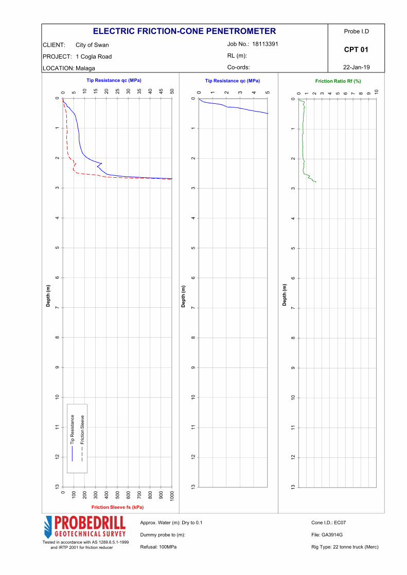
Cone Penetration Testing (CPT) at six locations, CPT01 to CPT06, extending to depths of 12 m below
ground level (bgl) or shallower refusal.
Hand Auger (HA) boreholes at six locations, HA01 to HA06, extending to depths of between 1.75 m bgl
and 2.30 m bgl.
In situ permeability testing within four of the hand auger locations, HA01, HA02, HA05 and HA06, using
the inverse hand auger method, at a depth of between 0.5 m and 1 m bgl.
Collection of soil samples for laboratory testing.

February 2019 18113391-001-R-Rev0
2
The test locations are shown on Figure 2. The coordinates of test locations were obtained using a handheld
GPS typically accurate to within about ± 5 m horizontally and are provided in Table 1.
Table 1: Test Location Summary
Location
Approximate Coordinates
(MGA94) Termination
Depth (m)
Termination
Reason Easting Northing
CPT01 396214 6474465 3.00 Refusal
CPT02 396236 6474505 12.0 Target Depth
CPT03 396168 6474501 12.0 Target Depth
CPT04 396174 6474448 12.0 Target Depth
CPT05 396164 6474411 12.0 Target Depth
CPT06 396226 6474409 12.0 Target Depth
HA01 396214 6474465 2.30 Refusal
HA02 396236 6474505 2.00 Refusal
HA03 396168 6474501 1.75 Refusal
HA04 396174 6474448 1.70 Refusal
HA05 396164 6474411 2.00 Refusal
HA06 396226 6474409 1.80 Refusal
The CPT was performed using a 22-tonne truck (Merc) supplied and operated by Probedrill Geotechnical
Survey Ltd. Testing was performed in accordance with AS 1289.6.5.1-1999. Results of the testing are
presented as plots of cone resistance (qc) and friction ratio (FR = fs/qc) × 100%) versus depth and are
presented in Appendix A. A method of soil classification by Roberts et al (1986) based on the values of qc and
FR is also included in Appendix A. Groundwater measurements were recorded in the hole remaining after the
removal of the CPT rods and are shown on the CPT reports.
The hand auger boreholes reports are included in Appendix B, along with a list of notes, abbreviations and the
method of soil description used in the report.
An Engineering Geologist from Golder positioned the test locations, drilled the hand auger boreholes and
logged the materials encountered, performed the falling head permeability testing and obtained soil samples
for laboratory testing. All soil materials were logged in accordance with AS 1726 (2017).
4.0 SITE CONDITIONS
4.1 Surface Conditions
The site is bound by Cogla Street to the east and Victoria Road to the south. Industrial warehouses are
located to the north and west of the site. At the time of the investigation, the site was undeveloped, and was
vegetated with grass, trees and shrubs. An unsealed, sand track follows the boundary of the site, and two
tracks cross the through centre of the site, parallel to Victoria Road. The site is generally flat.
At the time of the investigation fly-dumped rubbish was present over areas of the site. Refer to the
contamination investigation (Golder report reference 18113391-002-R-Rev0, dated February 2019) for more
information on this material.

February 2019 18113391-001-R-Rev0
3
4.2 Regional Geology
The 1:50,000 scale Environmental Geology Series Perth sheet published by the Geological Survey of Western
Australia shows that the site is generally located in a region where subsurface conditions comprise
Bassendean Sand which is described as “white to pale grey at surface, yellow at depth, fine to medium
grained, moderately sorted, sub-angular to sub-rounded”.
4.3 Subsurface Conditions
Subsurface conditions at the site can be generalised as comprising Bassendean Sand, which was observed
as:
SAND (SP), loose, fine to medium grained, rounded to sub-angular, dark brown to grey becoming pale
brown with 15 – 20% silt, trace rootlets, becoming orange-brown and dark brown to black, weakly
cemented, below about 1.4 m bgl, extending to depth ranging from about 1.7 m to 2.0 m bgl, overlying
SAND, dense to very dense, inferred weakly to moderately cemented sand (“Coffee Rock”), ranging from
about 1.7 m to 3.1 m bgl, overlying
SAND, medium dense, density increasing with depth, becoming dense below about 8.0 m bgl, extending
to the maximum depth investigated, 12.0 m bgl.
4.4 Groundwater
The Perth Groundwater Atlas (1997) shows the maximum historical groundwater for the site to be about
RL 31.5 m AHD.
The ground surface level at the site based on Nearmap is expected to be between about RL 34 m and
RL 35 m AHD. This suggests groundwater is likely to be encountered between about 2.5 m to 3.5 m below
ground surface level. Given the presence of the drainage basin to the north of the site, it is likely that ground
water levels would be controlled by this feature and the associated stormwater drainage network.
Groundwater was not observed during the geotechnical investigation, however, groundwater seepage was
encountered at 1.7 m bgl in HA03.
5.0 LABORATORY TESTING
Geotechnical laboratory testing was conducted on one sample recovered from the hand auger
boreholes. The testing was conducted at Golder’s NATA-accredited laboratory and comprised determination
of:
Particle size distribution tests on one sample.
Moisture content tests on one sample.
5.1 Geotechnical Results
Geotechnical laboratory test certificates are provided in Appendix C. A summary of the laboratory testing is
provided in Table 2.
Table 2: Summary of Geotechnical Laboratory Testing
Location Depth Soil
Classification
Moisture
Content (%)
Particle Size Distribution (% Passing)
Gravel Sand Fines
HA06 1.65-1.80 SAND (SP) 18.2 0 94 6
Notes: Gravel – material passing the 63 mm sieve and retained on the 2.36 mm sieve, Sand – material passing the 2.36 mm sieve and
retained on the 0.075 mm sieve, Fines – material passing the 0.075 mm sieve.

February 2019 18113391-001-R-Rev0
4
6.0 GEOTECHNICAL DISCUSSION
6.1 Preliminary Site Classification
We have carried out a preliminary assessment of the classification of the site in accordance with AS 2870-
2011 “Residential Slabs and Footings – Construction”. AS 2870-2011 defines the site classification on the
basis of a characteristic surface movement associated with settlement. It must be noted that AS 2870-2011 is
applicable to simple dwellings, houses or structures in similar size to homes and is not directly applicable to
multi-storey buildings. The structural designer should consider this when using the site classification.
We consider that a preliminary site classification of “Class A” is appropriate for the site.
6.2 Site Preparation
The following site preparation procedures are recommended for the development:
Remove all topsoil, trees, rubbish and any other deleterious materials from the site, including grubbing
out roots and removing organic matter. Any buried services, rubble, structural elements or other
unsuitable or deleterious material encountered during excavation should be removed.
Excavate to the footing foundation level where required. The in situ sands are likely to be suitable for re-
use as structural fill (following the removal of any deleterious material that may be present) and may be
stockpiled for later re-use if required.
Densify the exposed ground beneath floor slabs and footings by compacting to achieve the level of
compaction specified in Section 6.3 to a minimum of 0.9 m below the underside of footings or ground
slabs. This may require over-excavation and replacement of soil in compacted layers.
Where required, place approved granular fill to the required levels in layers of no greater than 0.3 m
loose thickness and compact each layer to achieve the level of compaction outlined in Section 6.3.
Confirm that the specified level of compaction, as defined in Section 6.3 has been achieved to a depth of
0.9 m below the base of footings and slabs by testing:
▪ Each spread footing excavation
▪ At 2.5 m centres along strip footing excavations, and
▪ On a grid at 5 m centres beneath slab-on-ground-floors.
The occurrence of undetected unsuitable fill cannot be dismissed. Any deleterious material must be removed
from beneath the building and replaced with approved granular fill. Allowance for such a contingency should
be made in earthworks quantities.
6.3 Compaction
In situ sand and approved sand fill should be moisture conditioned and compacted using suitable compaction
equipment to achieve a Perth sand penetrometer (PSP) blow count of at least 8 blows per 0.3 m
penetration. If difficulty arises in achieving the specified PSP blow counts, then a geotechnical engineer must
be engaged to provide further advice.
Over-excavation and replacement of loose material may be required where the minimum density cannot be
achieved.
Fill should be placed in horizontal layers of not greater than 0.3 m loose thickness. Each layer should be fully
compacted by suitable compaction equipment and carefully controlled to ensure even compaction over the full
area and depth of each layer.

February 2019 18113391-001-R-Rev0
5
Care will need to be taken when compacting in the vicinity of existing structures, such as the adjacent
warehouses, roads and buried services. This is particularly important if vibratory compaction is being carried
out. Tynan (1973)1 provides assistance with the selection of compaction equipment for use adjacent to
structures.
6.4 Shallow Footings
Based on the subsurface conditions encountered, pad and strip footings are considered appropriate to support
the development of the waste transfer station, subject to the proposed design loads.
A design involving individual pad and strip footings with minimum depths of embedment of 0.5 m and 1.0 m
below adjacent finished surface level have been examined and are presented in Table 3. The design
assumes that the recommended site preparations outlines in Section 6.2 have been undertaken.
Table 3: Allowable Bearing Pressure and Settlement Estimate Under Static Load
Minimum Depth
of Embedment
(m)
Minimum Plan
Dimension
(m)
Allowable
Bearing Pressure
(kPa)
Expected Settlement at
Allowable Bearing Pressure
(Static load) (mm)
Pad Footings
0.5
1.0 200 <5
2.0 220 5 to 10
3.0 240 10 to 15
1.0
1.0 250 <5
2.0 250 5 to 10
3.0 250 10 to 15
Strip Footings
0.5
0.5 130 <5
1.0 150 5 to 10
1.5 170 5 to 10
1.0
0.5 250 <5
1.0 250 5 to 10
1.5 250 10 to 15
Allowable bearing pressures for footings of intermediate plan dimensions to those tabulated can be
interpolated. Footings that have a plan dimension either smaller or larger than those covered by the tables
above will need to be considered individually along with other embedment depths or alternative footing
systems (e.g. screw piles). Footings carrying significant eccentric loading need to be assessed separately.
An allowable working bearing pressure of 250 kPa is considered an upper limit for shallow footings at this site
to limit total and differential settlement. Alternatively, higher footing settlements associated with higher
bearing pressures can be provided.
Settlement of the proposed structure will depend on a number of factors including the applied pressures,
footing sizes and base preparations. The estimates of settlements provided are for single isolated footings for
the working bearing pressure values shown. Differential settlements of up to half of the total estimated
settlement values are likely between footings of similar size, depth and loadings.
1 Tynan (1973) Ground Vibration and Damage Effects on Buildings, Australia Road Research Board, Special Report No. 11.

February 2019 18113391-001-R-Rev0
6
6.5 Excavations
Excavations in sandy soils across the site, should generally be achieved by using standard earthmoving
equipment, such as a 5-tonne (or greater mass) excavator. If excavations are expected between 2 m and 3 m
bgl, weakly to moderately cemented sand (“coffee rock”) is expected to be encountered, which may require a
larger excavator.
Excavations in sandy soils are particularly prone to instability, especially where groundwater is encountered.
Care must be exercised in such excavations and appropriate safety measures should be adopted where
necessary. A short-term slope angle of 1V:1.5H and a long-term slope angle of 1V:2H is recommended for
dry sands with no seepage, provided there are no structures or surcharges located behind the crest.
6.6 Earthquake Design
6.6.1 Earthquake Site Subsoil Classification
We have assessed the seismic subsoil classification in accordance with AS 1170.4-2007 based on the results
of the investigation and using published information. A site subsoil class of “Ce” – Shallow Soil is considered
appropriate for the site.
6.7 Drainage
6.7.1 Stormwater Disposal
Based on the results of the hydraulic testing, the sandy soils occurring within the top 2 m are expected to be
permeable and likely to be suitable for on-site disposal of stormwater.
Falling head permeability tests were located within HA01, HA02, HA05 and HA06 at a depth of about 0.5 m to
1.0 2m. The tests were carried out using the inverse hand auger hole test method2. The tests were repeated
three times at each location to simulate saturation of the soil immediately below the casing which comprised
sand. The permeability results returned infiltration values ranging between about 5 m per day and 20 m per
day. An infiltration rate of 10 m per day is considered appropriate for infiltration systems founded at about 1 m
depth.
The design of any stormwater infiltration system should allow for reductions in the soil permeability arising
from:
Proximity to groundwater level or low permeability soil layers (e.g. cemented sand).
Clogging of sands with fine particles through ongoing infiltration.
Densification of in situ sands from compaction during construction.
Proximity to groundwater, coffee rock, retaining walls or other below ground structures will impede infiltration
from adjacent stormwater infiltration cells. Design for restricting build-up of water against these items must be
considered.
Where shallow footings are adopted and are founded on compacted backfill or sand, stormwater infiltration
cells should not be positioned within 3 m of these footings to limit the potential for settlement of the footings
caused by localised mounding of infiltration water.
2 Cocks (2007) Disposal of Stormwater Runoff by Soakage in Perth Western Australia, Journal and News of the Australian Geomechanics Society, Volume 43, pp101-114

February 2019 18113391-001-R-Rev0
7
6.8 Potential Geotechnical Risks
The following section provides details of potential geotechnical risks that could influence the design and/or the
construction of the project based on our understanding of the geotechnical conditions. This summary has
been developed on the available geotechnical information and it is expected that the designers will make an
independent assessment of potential risks following development of the project design and following
completion of a detailed geotechnical investigation (if required).
6.8.1 Uncontrolled Fill
The in situ sand encountered at the site appeared to be clean, showing no evidence of being composed of
uncontrolled fill. However, cables, fridges, oil drums and potential asbestos sheeting, among other items,
were observed at surface across the site. Therefore, although not encountered during the investigation, the
presence of uncontrolled fill and contaminated materials cannot be dismissed. For more information, refer to
Golder report reference 18113391-002-R-Rev0, dated February 2019.
6.8.2 Excavation Stability and Proximity to Adjacent Buildings or Services
Based on our understanding of the project, excavations for footings or services may be required in close
proximity to existing roads, structures, underground services and public footpaths. Works in these areas
would need to be designed to minimize the potential impacts to existing roads, structures, underground
services and public footpaths. It is expected that the risk of damage to adjacent facilities could be reduced by:
Performing a dewatering investigation and preparation of a dewatering management plan (DMP)
Providing suitable retention systems to support the excavation at all stages of the excavation.
Avoiding the use of retention systems that involve vibration and/or allow ground movements (such as
steel sheet piling or soldier piles with lagging) as these may cause damage to adjacent structures, roads
and services.
6.8.3 Settlement
Loose zones were noted within 2 m of ground level. Without site preparation heavily loaded shallow footings
founded in this material may result in settlements in excess of serviceability limits.
6.8.4 Reduced Effectiveness of Soakwells
The presence of coffee rock, as encountered at the site between 2 m and 3 m bgl, has the potential to affect
the efficiency of soakwells. The coffee rock has lower permeability than the surrounding sand, which could
result in a perched groundwater table. If the sand surrounding the installed soakwell is saturated, the flow rate
from the soakwell itself will reduce. The seasonal groundwater variation could be investigated further by
installing a monitoring well or performing a review of the local stormwater drainage network once the project
design has developed further.
6.8.5 Acid Sulfate Soil
The Acid Sulfate Soil (ASS) Risk map published by the Department of Environment and Regulation (DER)
indicates that the probability of ASS occurrence within 3 m of natural surface soil at the site is moderate to
low. In our experience, Bassendean Sands below groundwater level are likely to be potential ASS.
In accordance with DER Guidelines, an ASS management plan will be required where the volume of ASS to
be disturbed is greater than 100 m3. An ASS investigation of this site is recommended should the volume of
soil to be disturbed is greater than 100 m3 or where dewatering is required.

February 2019 18113391-001-R-Rev0
8
7.0 IMPORTANT INFOMATION
Your attention is drawn to the document titled – “Important Information Relating to this Report”, which is
included in Appendix D of this report. The statements presented in that document are intended to inform a
reader of the report and about its proper use. There are important limitations as to who can use the report
and how it can be used. It is important that a reader of the report understands and has realistic expectations
about those matters. The Important Information document does not alter the obligations Golder Associates
has under the contract between it and its clients.

February 2019 18113391-001-R-Rev0
9
Signature Page
Golder Associates Pty Ltd
Hannah Breen Simon Hope
Engineering Geologist Senior Geotechnical Engineer
HSB/SNH/hsl
A.B.N. 64 006 107 857
Golder and the G logo are trademarks of Golder Associates Corporation
https://golderassociates.sharepoint.com/sites/101219/deliverables/001-r/18113391-001-r-rev0.docx

BENARA RD
CASSOWARY DR
TRUGANINA RD
WIDGEE RD
BELLEFIN
DR
VICTORIA RD
IRVINE DR
TONK I NHW
Y
HEPB
URN
AV
MULGUL RD
REID HWY
CAMB
OON
RD
ALTA LAGUNA CR
MANDILL A PDE
PELIC
ANPD
E
HAMELINDR
ALLINGTON AV
TRAD
E RD
ILLAWARRA CR
SOUTH
WYPERFELD GDNS
WOO DLE
IGHGDNS
GIRALIA PWY
BEACH RD
MCGI
LVRA
Y AV
MARSHALL RD
ORCH
IDAV
MITRALOOP
MCG RA T H PL
KILN
ST
PAVE
RS C
IR
GOR O KA GR
ROSELLA CIR
RAWL INNA
HTS
PARKINSON ST
LUDL O W MEWS
GROSE
WAY
CYGN
ET
CL
WATHEROO CT
TABUBI L
GDNS
NEWELL
WAY
CUSA
CK R
D
MUD LARK CR
SMITH
ERSO
NST
YANDALCR
CLIPPER DR
BELS
TEAD AV
JUNA DR
KIRKPATRICKCR
KIANDRAPDE
FORD
ER R
D
MERCANTILE WAY
IVORY ST
MIL LR O SE
DR
SUMMERLAKES PDE
HOLDEN DR
DENN
INUP
WA
Y
WEIR
RD
BOULDER RD
GUADALUPE DR
BLUEGUMRD
CRI MEAST
MALAGA DR
BERINGARRA AV
OXLE
IGH
DR
MILLY CT
CHAM B ERS
WAY
ARMSTRONG
WAY
HORSLAY WAY
STEWART WA Y
BELLEW WAY
MILLERICK WAY W EATHERILL WAY
NORANDA
BEECHBORO
MORLEY
BALLAJURA
MALAGA
CULLACABARDEE
BENNETTSPRINGS
WHITEMAN
395000
395000
396000
396000
397000
397000
398000
398000
6473
000
6473
000
6474
000
6474
000
6475
000
6475
000
6476
000
6476
000
CLIENTCITY OF SWAN
PROJECTLOT 269, 1 COGLA STREET, MALAGA
TITLELOCATION PLAN
18113391 001 R 0 1
2019.01.29TCJRPSNHSNH
PATH
: B:\C
ity_o
f_Swa
n\Mala
ga\99
_PRO
JECT
S\18
1133
91_L
ot_26
9_Co
gla_S
treet\
02_P
RODU
CTIO
N\MX
D\00
1-R\R
ev0\1
8113
391-0
01-R
-F001
-Rev
0.mxd
PRI
NTED
ON:
2019
-01-29
AT: 5
:11:44
PM
IF TH
IS M
EASU
REME
NT D
OES N
OT M
ATCH
WHA
T IS S
HOWN
, THE
SHEE
T SIZE
HAS
BEE
N MO
DIFIE
D FR
OM: IS
O A4
CONSULTANT
PROJECT NO. CONTROL REV. FIGURE
YYYY-MM-DDDESIGNEDPREPAREDREVIEWEDAPPROVED
25mm
0
NOTE:1. COORDINATE SYSTEM: GDA 1994 MGA ZONE 50
1. BASED ON INFORMATION PROVIDED BY AND WITH THE PERMISSION OF THE WESTERNAUSTRALIAN LAND INFORMATION AUTHORITY TRADING AS LANDGATE (2019).
REFERENCE:
0 500 1,000
METRES1:20,000
EASTBULLSBROOK
MOUNT HELENA
WOOROLOO
MORANGUP HILL
ARMADALE
MUCHEA
MIDLAND
QUINNS ROCKS
WANNEROO
FREMANTLE
PERTH
0 7.5 15
Kilometres
APPROXIMATEVIEW EXTENT
APPROXIMATESITE LOCATION

!.
!.
!.
!.
!.!.
!.
!.
!.
!.
!.!.
COGL
A ST
VICTORIA RD
HA01
HA02HA03
HA04
HA05 HA06
CPT01
CPT02CPT03
CPT04
CPT05 CPT06
396150
396150
396200
396200
396250
396250
6474
400
6474
400
6474
450
6474
450
6474
500
6474
500
6474
550
6474
550
CLIENTCITY OF SWAN
LEGEND
!.CONE PENETRATION ANDHAND AUGER TEST LOCATION
PROJECTLOT 269, 1 COGLA STREET, MALAGA
TITLESITE PLAN
18113391 001 R 0 2
2019.01.29TCJRPSNHSNH
PATH
: B:\C
ity_o
f_Swa
n\Mala
ga\99
_PRO
JECT
S\18
1133
91_L
ot_26
9_Co
gla_S
treet\
02_P
RODU
CTIO
N\MX
D\00
1-R\R
ev0\1
8113
391-0
01-R
-F002
-Rev
0.mxd
PRI
NTED
ON:
2019
-01-29
AT: 5
:08:07
PM
IF TH
IS M
EASU
REME
NT D
OES N
OT M
ATCH
WHA
T IS S
HOWN
, THE
SHEE
T SIZE
HAS
BEE
N MO
DIFIE
D FR
OM: IS
O A4
CONSULTANT
PROJECT NO. CONTROL REV. FIGURE
YYYY-MM-DDDESIGNEDPREPAREDREVIEWEDAPPROVED
25mm
0
NOTE:1. COORDINATE SYSTEM: GDA 1994 MGA ZONE 50
1. AERIAL IMAGERY SOURCED FROM NEARMAP DATED DECEMBER 2018.2. CADASTRE BASED ON INFORMATION PROVIDED BY AND WITH THE PERMISSION OF THEWESTERN AUSTRALIAN LAND INFORMATION AUTHORITY TRADING AS LANDGATE (2019).
REFERENCES:
0 25 50
METRES1:1,000

February 2019 18113391-001-R-Rev0
APPENDIX A
Cone Penetration Test Reports

LOCATION:
PROJECT:
CLIENT:
Co-ords:
RL (m):
Job No.:
22-Jan-19
Probe I.DELECTRIC FRICTION-CONE PENETROMETER
CPT 01
Rig Type: 22 tonne truck (Merc)Tested in accordance with AS 1289.6.5.1-1999 and IRTP 2001 for friction reducer
18113391
Malaga
1 Cogla Road
City of Swan
Refusal: 100MPa
Approx. Water (m): Dry to 0.1
Dummy probe to (m): File: GA3914G
Cone I.D.: EC07
0 1 2 3 4 5 6 7 8 9 10
01
23
45
67
89
1011
1213
Friction Ratio Rf (%)
Dep
th (m
)
0 1 2 3 4 5
01
23
45
67
89
1011
1213
Tip Resistance qc (MPa)
Dep
th (m
)
0
100
200
300
400
500
600
700
800
900
1000
0 5 10 15 20 25 30 35 40 45 50
01
23
45
67
89
1011
1213
Friction Sleeve fs (kPa)
Tip Resistance qc (MPa)
Dep
th (m
)
Tip
Res
ista
nce
Fric
tion
Slee
ve

LOCATION:
PROJECT:
CLIENT:
Co-ords:
RL (m):
Job No.:
22-Jan-19
Probe I.DELECTRIC FRICTION-CONE PENETROMETER
CPT 01A
Rig Type: 22 tonne truck (Merc)Tested in accordance with AS 1289.6.5.1-1999 and IRTP 2001 for friction reducer
18113391
Malaga
1 Cogla Road
City of Swan
Refusal: 92MPa
Approx. Water (m): Dry to 0.1
Dummy probe to (m): File: GA3915G
Cone I.D.: EC07
0 1 2 3 4 5 6 7 8 9 10
01
23
45
67
89
1011
1213
Friction Ratio Rf (%)
Dep
th (m
)
0 1 2 3 4 5
01
23
45
67
89
1011
1213
Tip Resistance qc (MPa)
Dep
th (m
)
0
100
200
300
400
500
600
700
800
900
1000
0 5 10 15 20 25 30 35 40 45 50
01
23
45
67
89
1011
1213
Friction Sleeve fs (kPa)
Tip Resistance qc (MPa)
Dep
th (m
)
Tip
Res
ista
nce
Fric
tion
Slee
ve

LOCATION:
PROJECT:
CLIENT:
Co-ords:
RL (m):
Job No.:
22-Jan-19
Probe I.DELECTRIC FRICTION-CONE PENETROMETER
CPT 02
Rig Type: 22 tonne truck (Merc)Tested in accordance with AS 1289.6.5.1-1999 and IRTP 2001 for friction reducer
18113391
Malaga
1 Cogla Road
City of Swan
Refusal:
Approx. Water (m): Dry to 0.1
Dummy probe to (m): File: GA3916G
Cone I.D.: EC07
0 1 2 3 4 5 6 7 8 9 10
01
23
45
67
89
1011
1213
Friction Ratio Rf (%)
Dep
th (m
)
0 1 2 3 4 5
01
23
45
67
89
1011
1213
Tip Resistance qc (MPa)
Dep
th (m
)
0
100
200
300
400
500
600
700
800
900
1000
0 5 10 15 20 25 30 35 40 45 50
01
23
45
67
89
1011
1213
Friction Sleeve fs (kPa)
Tip Resistance qc (MPa)
Dep
th (m
)
Tip
Res
ista
nce
Fric
tion
Slee
ve

LOCATION:
PROJECT:
CLIENT:
Co-ords:
RL (m):
Job No.:
22-Jan-19
Probe I.DELECTRIC FRICTION-CONE PENETROMETER
CPT 03
Rig Type: 22 tonne truck (Merc)Tested in accordance with AS 1289.6.5.1-1999 and IRTP 2001 for friction reducer
18113391
Malaga
1 Cogla Road
City of Swan
Refusal:
Approx. Water (m): Dry to 0.1
Dummy probe to (m): File: GA3917G
Cone I.D.: EC07
0 1 2 3 4 5 6 7 8 9 10
01
23
45
67
89
1011
1213
Friction Ratio Rf (%)
Dep
th (m
)
0 1 2 3 4 5
01
23
45
67
89
1011
1213
Tip Resistance qc (MPa)
Dep
th (m
)
0
100
200
300
400
500
600
700
800
900
1000
0 5 10 15 20 25 30 35 40 45 50
01
23
45
67
89
1011
1213
Friction Sleeve fs (kPa)
Tip Resistance qc (MPa)
Dep
th (m
)
Tip
Res
ista
nce
Fric
tion
Slee
ve

LOCATION:
PROJECT:
CLIENT:
Co-ords:
RL (m):
Job No.:
22-Jan-19
Probe I.DELECTRIC FRICTION-CONE PENETROMETER
CPT 04
Rig Type: 22 tonne truck (Merc)Tested in accordance with AS 1289.6.5.1-1999 and IRTP 2001 for friction reducer
18113391
Malaga
1 Cogla Road
City of Swan
Refusal:
Approx. Water (m): Dry to 0.1
Dummy probe to (m): File: GA3918G
Cone I.D.: EC07
0 1 2 3 4 5 6 7 8 9 10
01
23
45
67
89
1011
1213
Friction Ratio Rf (%)
Dep
th (m
)
0 1 2 3 4 5
01
23
45
67
89
1011
1213
Tip Resistance qc (MPa)
Dep
th (m
)
0
100
200
300
400
500
600
700
800
900
1000
0 5 10 15 20 25 30 35 40 45 50
01
23
45
67
89
1011
1213
Friction Sleeve fs (kPa)
Tip Resistance qc (MPa)
Dep
th (m
)
Tip
Res
ista
nce
Fric
tion
Slee
ve

LOCATION:
PROJECT:
CLIENT:
Co-ords:
RL (m):
Job No.:
22-Jan-19
Probe I.DELECTRIC FRICTION-CONE PENETROMETER
CPT 05
Rig Type: 22 tonne truck (Merc)Tested in accordance with AS 1289.6.5.1-1999 and IRTP 2001 for friction reducer
18113391
Malaga
1 Cogla Road
City of Swan
Refusal:
Approx. Water (m): Dry to 0.1
Dummy probe to (m): File: GA3919G
Cone I.D.: EC07
0 1 2 3 4 5 6 7 8 9 10
01
23
45
67
89
1011
1213
Friction Ratio Rf (%)
Dep
th (m
)
0 1 2 3 4 5
01
23
45
67
89
1011
1213
Tip Resistance qc (MPa)
Dep
th (m
)
0
100
200
300
400
500
600
700
800
900
1000
0 5 10 15 20 25 30 35 40 45 50
01
23
45
67
89
1011
1213
Friction Sleeve fs (kPa)
Tip Resistance qc (MPa)
Dep
th (m
)
Tip
Res
ista
nce
Fric
tion
Slee
ve

LOCATION:
PROJECT:
CLIENT:
Co-ords:
RL (m):
Job No.:
22-Jan-19
Probe I.DELECTRIC FRICTION-CONE PENETROMETER
CPT 06
Rig Type: 22 tonne truck (Merc)Tested in accordance with AS 1289.6.5.1-1999 and IRTP 2001 for friction reducer
18113391
Malaga
1 Cogla Road
City of Swan
Refusal:
Approx. Water (m): Dry to 0.1
Dummy probe to (m): File: GA3920G
Cone I.D.: EC07
0 1 2 3 4 5 6 7 8 9 10
01
23
45
67
89
1011
1213
Friction Ratio Rf (%)
Dep
th (m
)
0 1 2 3 4 5
01
23
45
67
89
1011
1213
Tip Resistance qc (MPa)
Dep
th (m
)
0
100
200
300
400
500
600
700
800
900
1000
0 5 10 15 20 25 30 35 40 45 50
01
23
45
67
89
1011
1213
Friction Sleeve fs (kPa)
Tip Resistance qc (MPa)
Dep
th (m
) Tip
Res
ista
nce
Fric
tion
Slee
ve
February 2019 18113391-001-R-Rev0
APPENDIX B
Hand Auger Borehole Reports

Updated in line with Australian Standard Geotechnical Site Investigations (AS1726:2017) GAP Form No.5 RL9
January 2018
METHOD OF SOIL DESCRIPTION USED ON BOREHOLE AND TEST PIT REPORTS
SYMBOLS
FILL
CLAY (CL, CI or CH)
GRAVEL (GW, GP, GM or GC)
ORGANIC SOILS (OL, OH or Pt)
SAND (SW, SP, SM or SC)
COBBLES or BOULDERS
SILT (ML or MH)
Combinations of these basic symbols may be used to indicate mixed materials such as sandy clay.
CLASSIFICATION AND INFERRED STRATIGRAPHY
Soil and Rock is classified and described in Reports of Boreholes and Test Pits using the preferred method given in AS1726-2017. The material properties are assessed in the field by visual/tactile methods.
Particle Size Plasticity Properties
Soil Group Sub Division Particle Size
BOULDERS > 200 mm
COBBLES 63 to 200 mm
GRAVEL
Coarse 19 to 63 mm
Medium 6.7 to 19 mm
Fine 2.36 to 6.7 mm
SAND
Coarse 0.6 to 2.36 mm
Medium 0.21 to 0.6 mm
Fine 0.075 to 0.21 mm
SILT 0.002 to 0.075 mm
CLAY ˂ 0.002 mm
MOISTURE CONDITION
Symbol Term Description D Dry Sands and gravels are free flowing. Clays and silts may be brittle or friable and powdery. M Moist Soils are darker than in dry condition and may feel cool. Sands and gravels tend to cohere. W Wet Soils exude free water. Sand and gravels tend to cohere. Moisture condition for fine grained soils is described relative to the plastic limit or liquid limit as specified in AS1726-2017.
CONSISTENCY AND DENSITY
Fine Grained Soils Coarse Grained Soils
Symbol Term Undrained Shear Strength Symbol Term Density Index (%) SPN “N” *
VS Very Soft 0 to 12 kPa VL Very Loose Less than 15 0 to 4
S Soft 12 to 25 kPa L Loose 15 to 35 4 to 10
F Firm 25 to 50 kPa MD Medium Dense 35 to 65 10 to 30
St Stiff 50 to 100 kPa D Dense 65 to 85 30 to 50
VSt Very Stiff 100 to 200 kPa VD Very Dense Above 85 Above 50
H Hard Above 200 kPa
Fr Friable -
In the absence of test results, consistency and density may be assessed from correlations with the observed behaviour of the material. * SPT correlations are not stated in AS1726-2017, and may be subject to corrections for overburden pressure and equipment type.
CEMENTATION
Weakly Cemented The soil may be easily disaggregated by hand in air or water.
Moderately Cemented Effort is required to disaggregate the soil by hand in air or water.

Updated in line with Australian Standard Geotechnical Site Investigations (AS1726:2017) GAP Form No.6 RL8 January 2018
EXPLANATION OF NOTES, ABBREVIATIONS & TERMS USED ON BOREHOLE AND TEST PIT REPORTS
DRILLING/EXCAVATION METHOD
ADH Hollow auger drilling EX Excavator PQ3 Diamond core - 83 mm
ADT Auger drilling with tc-bit HA Hand auger PT Push tube sampling
ADV Auger drilling with v-bit HAND Excavated by hand methods RAB Rotary air blast
AIRCORE Aircore HMLC Diamond core - 63 mm RC Reverse circulation
AT Air track HQ3 Diamond core - 61 mm RT Rock roller
BH Backhoe bucket JET Jetting SONIC Sonic drilling
CT Cable tool rig MZ Mazier tube sampling SPT Standard penetration testing
DTC Diatube coring NDD Non-destructive digging U Undisturbed tube sampling
EE Existing excavation NMLC Diamond core - 52 mm WB Washbore drilling
EPT Extruded push tube NQ3 Diamond core - 45 mm
PENETRATION/EXCAVATION RESISTANCE
L Low resistance. Rapid penetration possible with little effort from the equipment used. M Medium resistance. Excavation/possible at an acceptable rate with moderate effort from the equipment used. H High resistance to penetration/excavation. Further penetration is possible at a slow rate and requires significant
effort from the equipment. R Refusal or Practical Refusal. No further progress possible without the risk of damage or unacceptable wear to
the digging implement or machine. These assessments are subjective and are dependent on many factors including the equipment power, weight, condition of excavation or drilling tools, and the experience of the operator.
WATER
Water level at date shown Partial water loss Water inflow Complete water loss
GROUNDWATER NOT OBSERVED
The observation of groundwater, whether present or not, was not possible due to drilling water, surface seepage or cave in of the borehole/test pit.
GROUNDWATER NOT ENCOUNTERED
The borehole/test pit was dry soon after excavation. However, groundwater could be present in less permeable strata. Inflow may have been observed had the borehole/test pit been left open for a longer period.
SAMPLING AND TESTING
SPT Standard Penetration Test to AS1289.6.3.1-2004 4,7,11 N=18 4,7,11 = Blows per 150mm. N = Blows per 300mm penetration following 150mm seating 30/80 mm Where practical refusal occurs, the blows and penetration for that interval are reported RW Penetration occurred under the rod weight only HW Penetration occurred under the hammer and rod weight only HB Hammer double bouncing on anvil DS Disturbed sample BDS Bulk disturbed sample G Gas Sample W Water Sample FP Field permeability test over section noted FV Field vane shear test expressed as uncorrected shear strength (sv = peak value, sr = residual value) PID Photoionisation Detector reading in ppm PM Pressuremeter test over section noted PP Pocket penetrometer test expressed as instrument reading in kPa U63 Thin walled tube sample - number indicates nominal sample diameter in millimetres WPT Water pressure test DCP Dynamic cone penetration test CPT Cone penetration test CPTu Cone penetration test with pore pressure (u) measurement
RANKING OF VISUALLY OBSERVABLE CONTAMINATION AND ODOUR (for specific soil contamination assessment projects)
R = 0 R = 1 R = 2 R = 3
No visible evidence of contamination Slight evidence of visible contamination Visible contamination Significant visible contamination
R = A R = B R = C R = D
No non-natural odours identified Slight non-natural odours identified Moderate non-natural odours identified Strong non-natural odours identified
ROCK CORE RECOVERY
TCR = Total Core Recovery (%)
RQD = Rock Quality Designation (%)
SCR = Solid Core Recovery (%)
F = Fracture Frequency
100runcoreofLength
eredcovrecoreofLength 100
runcoreofLength
mm100coreoflengthsAxial
100
runcoreofLength
recovered core alcyclindric of Length
(m) zoneofLength
defectsofNo.

Updated in line with Australian Standard Geotechnical Site Investigations (AS1726:2017) GAP Form No.7 RL7January 2018
TERMS FOR ROCK MATERIAL STRENGTH & WEATHERING AND ABBREVIATIONS FOR DEFECT DESCRIPTIONS
STRENGTH Symbol Term UCS (MPa) Field Guide
VLVery Low
0.6 to 2 Material crumbles under firm blows with sharp end of pick; can be peeled with knife; too hard to cut a triaxial sample by hand. Pieces up to 30 mm can be broken by finger pressure.
L Low 2 to 6
Easily scored with a knife; indentations 1 mm to 3 mm show in the specimen with firm blows of pick point; has dull sound under hammer. A piece of core 150 mm long by 50 mm diameter may be broken by hand. Sharp edges of core may be friable and break during handling.
M Medium 6 to 20 Readily scored with a knife; a piece of core 150 mm long by 50 mm diameter can be broken by hand with difficulty.
H High 20 to 60 A piece of core 150 mm long by 50 mm diameter cannot be broken by hand but can be broken with pick with a single firm blow; rock rings under hammer.
VHVery High
60 to 200 Hand specimen breaks with pick after more than one blow; rock rings under hammer.
EHExtremely
High >200
Specimen requires many blows with geological pick to break through intact material; rock rings under hammer.
Material with strength less than ‘Very Low’ shall be described using soil characteristics. The presence of an original rock structure, fabric or texture should be noted, if relevant. ROCK MATERIAL WEATHERING
Symbol Term Field Guide
RSResidual
Soil
Material is weathered to such an extent that it has soil properties. Mass structure and material texture and fabric of original rock are no longer visible, but the soil has not been significantly transported.
XW Extremely Weathered
Material is weathered to such an extent that it has soil properties. Mass structure and material texture and fabric of original rock are still visible.
DW
HW Highly
Weathered
The whole of the rock material is discoloured, usually by iron staining or bleaching to the extent that the colour of the original rock is not recognizable. Rock strength is significantly changed by weathering. Some primary minerals have weathered to clay minerals. Porosity may be increased by leaching, or may be decreased due to deposition of weathering products in pores.
MWModerately Weathered
The whole of the rock material is discoloured, usually by iron staining or bleaching to the extent that the colour of the original rock is not recognizable, but shows little or no change of strength from fresh rock.
SW Slightly
Weathered Rock is partially discoloured with staining or bleaching along joints but shows little or no change of strength from fresh rock.
FR Fresh Rock shows no sign of decomposition of individual minerals or colour changes.ABBREVIATIONS FOR DEFECT TYPES AND DESCRIPTIONSDefect Type Coating or Infilling RoughnessP Parting Cn Clean VRo Very RoughX Foliation Sn Stain Ro RoughL Cleavage Ve Veneer Sm SmoothC Contact Ct Coating Po PolishedJ Joint In Infill Sl SlickensidedSSu Sheared Surface Vertical Boreholes – The dip
(inclination from horizontal) of the defect is given. Inclined Boreholes – The inclination is measured as the acute angle between the core axis and the vertical direction.
SS Sheared Seam PlanaritySZ Sheared Zone Pl PlanarCS Crushed Seam Cv CurvedIS Infilled Seam Un UndulatingEWS Extremely Weathered Seam St Stepped V Vein Ir Irregular

L
M
R
SANDfine to medium grained, rounded to sub-rounded, darkbrown-grey, with silt, trace rootlets
SANDfine to medium grained, rounded to sub-angular, pale brown,mottled dark brown, trace rootlets
SANDfine grained, rounded to sub-rounded, orange-brown
SANDfine grained, rounded to sub-rounded, dark brown-black,sulphurous
trace gravel, medium to coarse grained, rounded to sub-roundedof cemented sand
END OF HAND AUGER @ 2.30 mREFUSALGROUNDWATER NOT ENCOUNTEREDBACKFILLED
SP
SP
SP
SP
0.80
1.10
2.00
2.15
HA
D
M
L
MD -D
water added to assist drilling
Infiltration test undertaken at 0.55 m
SHEET: 1 OF 1
Field Material DescriptionSamplingDrilling
PE
NE
TR
AT
ION
RE
SIS
TA
NC
E
SOIL/ROCK MATERIAL DESCRIPTION
RE
CO
VE
RE
D
GR
OU
P S
YM
BO
L
WA
TE
R
RLDEPTH
DE
PT
H(m
etre
s)
ME
TH
OD
GR
AP
HIC
LOG
SAMPLE ORFIELD TEST
GAP gINT FN. F01aRL3
CLIENT:
PROJECT:
LOCATION:
JOB NO:
DATE: 22-1-19
DATE: 25-2-19
This report of hand augered borehole must be read in conjunction with accompanying notes and abbreviations. It has beenprepared for geotechnical purposes only, without attempt to assess possible contamination. Any references to potentialcontamination are for information only and do not necessarily indicate the presence or absence of soil or groundwater
contamination.
City of Swan
Lot 269 Cogla Street
Malaga
18113391
COORDS: 396214 m E 6474465 m N MGA94 50
SURFACE RL: DATUM: AHD
INCLINATION: -90°
HOLE DEPTH: 2.30 m
LOGGED: HB
CHECKED: SNH
REPORT OF HAND AUGERED BOREHOLE: HA01
GA
P 8
_16.
6 LI
B.G
LB L
og G
AP
NO
N-C
OR
ED
FU
LL P
AG
E 1
8113
391
_CO
S_M
ALA
GA
.GP
J <
<D
raw
ingF
ile>
> 2
5-02
-201
9 15
:55
8.3
0.00
4 D
atge
l Too
ls
MO
IST
UR
EC
ON
DIT
ION
CO
NS
IST
EN
CY
DE
NS
ITY
STRUCTURE ANDADDITIONAL
OBSERVATIONS
0.0
0.5
1.0
1.5
2.0
2.5
3.0
3.5
4.0
4.5
5.0

L
M
R
SANDfine to medium grained, rounded to sub-rounded, darkbrown-grey, with 15-20% low plasticity silt, trace rootlets
SANDfine grained, rounded to sub-rounded, pale brown
SANDfine to medium grained, rounded to sub-rounded, dark red-brown,trace silt, trace rootlets
END OF HAND AUGER @ 2.00 mREFUSALGROUNDWATER NOT ENCOUNTEREDBACKFILLED
SP
SP
SP
0.70
1.90
HA D
L
MD -D
water added to assist drilling
Infiltration test undertaken at 0.6 m
SHEET: 1 OF 1
Field Material DescriptionSamplingDrilling
PE
NE
TR
AT
ION
RE
SIS
TA
NC
E
SOIL/ROCK MATERIAL DESCRIPTION
RE
CO
VE
RE
D
GR
OU
P S
YM
BO
L
WA
TE
R
RLDEPTH
DE
PT
H(m
etre
s)
ME
TH
OD
GR
AP
HIC
LOG
SAMPLE ORFIELD TEST
GAP gINT FN. F01aRL3
CLIENT:
PROJECT:
LOCATION:
JOB NO:
DATE: 22-1-19
DATE: 25-2-19
This report of hand augered borehole must be read in conjunction with accompanying notes and abbreviations. It has beenprepared for geotechnical purposes only, without attempt to assess possible contamination. Any references to potentialcontamination are for information only and do not necessarily indicate the presence or absence of soil or groundwater
contamination.
City of Swan
Lot 269 Cogla Street
Malaga
18113391
COORDS: 396236 m E 6474505 m N MGA94 50
SURFACE RL: DATUM: AHD
INCLINATION: -90°
HOLE DEPTH: 2.00 m
LOGGED: HB
CHECKED: SNH
REPORT OF HAND AUGERED BOREHOLE: HA02
GA
P 8
_16.
6 LI
B.G
LB L
og G
AP
NO
N-C
OR
ED
FU
LL P
AG
E 1
8113
391
_CO
S_M
ALA
GA
.GP
J <
<D
raw
ingF
ile>
> 2
5-02
-201
9 15
:55
8.3
0.00
4 D
atge
l Too
ls
MO
IST
UR
EC
ON
DIT
ION
CO
NS
IST
EN
CY
DE
NS
ITY
STRUCTURE ANDADDITIONAL
OBSERVATIONS
0.0
0.5
1.0
1.5
2.0
2.5
3.0
3.5
4.0
4.5
5.0

L-M
MR
SANDfine to medium grained, rounded to sub-angular, darkbrown-grey, with 15-20% silt, trace rootlets, trace gravel, fine tocoarse grained, sub-rounded to angular of coffee rock andcobbles of limestone fine to medium grained, angular
with gravel and cobbles, about 20%
SANDfine grained, rounded to sub-angular, blue-grey
SANDfine to medium grained, sub-rounded to sub-angular, darkbrown-black, trace silt
END OF HAND AUGER @ 1.75 mREFUSALBACKFILLEDseepage at 1.7m
SP
SP
SP
0.40
0.80
1.70
HA
D
M
L
MD -D
water added to assist drilling
SHEET: 1 OF 1
Field Material DescriptionSamplingDrilling
PE
NE
TR
AT
ION
RE
SIS
TA
NC
E
SOIL/ROCK MATERIAL DESCRIPTION
RE
CO
VE
RE
D
GR
OU
P S
YM
BO
L
WA
TE
R
RLDEPTH
DE
PT
H(m
etre
s)
ME
TH
OD
GR
AP
HIC
LOG
SAMPLE ORFIELD TEST
GAP gINT FN. F01aRL3
CLIENT:
PROJECT:
LOCATION:
JOB NO:
DATE: 22-1-19
DATE: 25-2-19
This report of hand augered borehole must be read in conjunction with accompanying notes and abbreviations. It has beenprepared for geotechnical purposes only, without attempt to assess possible contamination. Any references to potentialcontamination are for information only and do not necessarily indicate the presence or absence of soil or groundwater
contamination.
City of Swan
Lot 269 Cogla Street
Malaga
18113391
COORDS: 396168 m E 6474501 m N MGA94 50
SURFACE RL: DATUM: AHD
INCLINATION: -90°
HOLE DEPTH: 1.75 m
LOGGED: HB
CHECKED: SNH
REPORT OF HAND AUGERED BOREHOLE: HA03
GA
P 8
_16.
6 LI
B.G
LB L
og G
AP
NO
N-C
OR
ED
FU
LL P
AG
E 1
8113
391
_CO
S_M
ALA
GA
.GP
J <
<D
raw
ingF
ile>
> 2
5-02
-201
9 15
:55
8.3
0.00
4 D
atge
l Too
ls
MO
IST
UR
EC
ON
DIT
ION
CO
NS
IST
EN
CY
DE
NS
ITY
STRUCTURE ANDADDITIONAL
OBSERVATIONS
0.0
0.5
1.0
1.5
2.0
2.5
3.0
3.5
4.0
4.5
5.0

L
M
R
SANDfine to medium grained, rounded to sub-angular, grey-brown,trace silt, trace rootlets
SANDfine to medium grained, sub-rounded to sub-angular, pale yellow
pale brown
SANDfine to medium grained, rounded to sub-rounded, dark red-brown,with gravel, fine to coarse, sub-rounded to angular coffee rock,about 10-20%
END OF HAND AUGER @ 1.70 mREFUSALGROUNDWATER NOT ENCOUNTEREDBACKFILLED
SP
SP
SP
0.30
1.20
1.40
HA
seep
age
D
M
L
MD -D
water added to assist drilling
SHEET: 1 OF 1
Field Material DescriptionSamplingDrilling
PE
NE
TR
AT
ION
RE
SIS
TA
NC
E
SOIL/ROCK MATERIAL DESCRIPTION
RE
CO
VE
RE
D
GR
OU
P S
YM
BO
L
WA
TE
R
RLDEPTH
DE
PT
H(m
etre
s)
ME
TH
OD
GR
AP
HIC
LOG
SAMPLE ORFIELD TEST
GAP gINT FN. F01aRL3
CLIENT:
PROJECT:
LOCATION:
JOB NO:
DATE: 22-1-19
DATE: 25-2-19
This report of hand augered borehole must be read in conjunction with accompanying notes and abbreviations. It has beenprepared for geotechnical purposes only, without attempt to assess possible contamination. Any references to potentialcontamination are for information only and do not necessarily indicate the presence or absence of soil or groundwater
contamination.
City of Swan
Lot 269 Cogla Street
Malaga
18113391
COORDS: 396174 m E 6474448 m N MGA94 50
SURFACE RL: DATUM: AHD
INCLINATION: -90°
HOLE DEPTH: 1.70 m
LOGGED: HB
CHECKED: SNH
REPORT OF HAND AUGERED BOREHOLE: HA04
GA
P 8
_16.
6 LI
B.G
LB L
og G
AP
NO
N-C
OR
ED
FU
LL P
AG
E 1
8113
391
_CO
S_M
ALA
GA
.GP
J <
<D
raw
ingF
ile>
> 2
5-02
-201
9 15
:56
8.3
0.00
4 D
atge
l Too
ls
MO
IST
UR
EC
ON
DIT
ION
CO
NS
IST
EN
CY
DE
NS
ITY
STRUCTURE ANDADDITIONAL
OBSERVATIONS
0.0
0.5
1.0
1.5
2.0
2.5
3.0
3.5
4.0
4.5
5.0

L
M
R
SANDfine to medium grained, rounded to sub-rounded, dark brown,trace silt, trace rootlets
Silty SANDfine grained, rounded to sub-rounded, grey, approx 15-20% silt
SANDfine grained, rounded to sub-rounded, grey-white
dark black
dark red-brown
with gravel approx 15%, cemented sand and coffee rock,sub-angular to sub-rounded, medium to coarse grained, tracelignite
END OF HAND AUGER @ 2.00 mREFUSALGROUNDWATER NOT ENCOUNTEREDBACKFILLED
SP
SM
SP
0.50
0.80
1.60
1.80
1.90
HA
D
M
L
MD
D
water added to assist drilling
Infiltration test undertaken at 0.8 m
SHEET: 1 OF 1
Field Material DescriptionSamplingDrilling
PE
NE
TR
AT
ION
RE
SIS
TA
NC
E
SOIL/ROCK MATERIAL DESCRIPTION
RE
CO
VE
RE
D
GR
OU
P S
YM
BO
L
WA
TE
R
RLDEPTH
DE
PT
H(m
etre
s)
ME
TH
OD
GR
AP
HIC
LOG
SAMPLE ORFIELD TEST
GAP gINT FN. F01aRL3
CLIENT:
PROJECT:
LOCATION:
JOB NO:
DATE: 22-1-19
DATE: 25-2-19
This report of hand augered borehole must be read in conjunction with accompanying notes and abbreviations. It has beenprepared for geotechnical purposes only, without attempt to assess possible contamination. Any references to potentialcontamination are for information only and do not necessarily indicate the presence or absence of soil or groundwater
contamination.
City of Swan
Lot 269 Cogla Street
Malaga
18113391
COORDS: 396164 m E 6474411 m N MGA94 50
SURFACE RL: DATUM: AHD
INCLINATION: -90°
HOLE DEPTH: 2.00 m
LOGGED: HB
CHECKED: SNH
REPORT OF HAND AUGERED BOREHOLE: HA05
GA
P 8
_16.
6 LI
B.G
LB L
og G
AP
NO
N-C
OR
ED
FU
LL P
AG
E 1
8113
391
_CO
S_M
ALA
GA
.GP
J <
<D
raw
ingF
ile>
> 2
5-02
-201
9 15
:56
8.3
0.00
4 D
atge
l Too
ls
MO
IST
UR
EC
ON
DIT
ION
CO
NS
IST
EN
CY
DE
NS
ITY
STRUCTURE ANDADDITIONAL
OBSERVATIONS
0.0
0.5
1.0
1.5
2.0
2.5
3.0
3.5
4.0
4.5
5.0

L
M
R
SANDfine to medium grained, rounded to sub-rounded, dark grey, tracesilt, trace rootlets
SANDfine to medium grained, rounded to sub-rounded, grey-white
brown-white
black, trace gravel, sub-round to sub-angular of cemented sand,fine to medium grained, organic sulphurous
END OF HAND AUGER @ 1.80 mREFUSALGROUNDWATER NOT ENCOUNTEREDBACKFILLED
SP
SP0.40
1.20
1.65
HA
D
M
L
MD -D
Water added to assist drilling
Infiltration test undertaken at 0.7 m
SHEET: 1 OF 1
Field Material DescriptionSamplingDrilling
PE
NE
TR
AT
ION
RE
SIS
TA
NC
E
SOIL/ROCK MATERIAL DESCRIPTION
RE
CO
VE
RE
D
GR
OU
P S
YM
BO
L
WA
TE
R
RLDEPTH
DE
PT
H(m
etre
s)
ME
TH
OD
GR
AP
HIC
LOG
SAMPLE ORFIELD TEST
GAP gINT FN. F01aRL3
CLIENT:
PROJECT:
LOCATION:
JOB NO:
DATE: 22-1-19
DATE: 25-2-19
This report of hand augered borehole must be read in conjunction with accompanying notes and abbreviations. It has beenprepared for geotechnical purposes only, without attempt to assess possible contamination. Any references to potentialcontamination are for information only and do not necessarily indicate the presence or absence of soil or groundwater
contamination.
City of Swan
Lot 269 Cogla Street
Malaga
18113391
COORDS: 396226 m E 6474409 m N MGA94 50
SURFACE RL: DATUM: AHD
INCLINATION: -90°
HOLE DEPTH: 1.80 m
LOGGED: HB
CHECKED: SNH
REPORT OF HAND AUGERED BOREHOLE: HA06
GA
P 8
_16.
6 LI
B.G
LB L
og G
AP
NO
N-C
OR
ED
FU
LL P
AG
E 1
8113
391
_CO
S_M
ALA
GA
.GP
J <
<D
raw
ingF
ile>
> 2
5-02
-201
9 15
:56
8.3
0.00
4 D
atge
l Too
ls
MO
IST
UR
EC
ON
DIT
ION
CO
NS
IST
EN
CY
DE
NS
ITY
STRUCTURE ANDADDITIONAL
OBSERVATIONS
0.0
0.5
1.0
1.5
2.0
2.5
3.0
3.5
4.0
4.5
5.0

February 2019 18113391-001-R-Rev0
APPENDIX C
Geotechnical Laboratory
Certificates

-
mm
mm
mm
mm
mm
mm
mm
mm
mm
mm
mm
mm
mm
μm
μm
μm
μm
μm
x y x y x y x y x y x y x y
0.075 0% 2.36 0% 63 0% 200 0% 0.001 10% 0.001 30% 0.001 60%
0.075 6% 2.36 100% 63 100% 200 100% 0.163 10% 0.280 30% 0.389 60%
SIEVE 125 75 63 53 37.5 26.5 19 13.2 9.5 6.7 4.75 2.36 1.18 0.6 0.425 0.3 0.15 0.075
RESULT 100% 100% 100% 100% 100% 100% 100% 100% 100% 100% 100% 100% 100% 90% 71% 33% 8% 6%
LBS #N/A #N/A #N/A #N/A #N/A #N/A #N/A #N/A #N/A #N/A #N/A #N/A #N/A #N/A #N/A #N/A #N/A #N/A
UBS #N/A #N/A #N/A #N/A #N/A #N/A #N/A #N/A #N/A #N/A #N/A #N/A #N/A #N/A #N/A #N/A #N/A #N/A
These tests were carried out in accordance with the Australian standards identified in this certificate.
13.2
33%
8%
6%
71%
0.389
D60
0.163 0.280
D10
Phone: +61 (0)8 9441 0700 [email protected]
(>75 μm - <2.36 mm)
Web: www.golder.com.auFax: +61 (0)8 9441 0701 E-mail:
75
26.5
Gravel*
LSM = Linear shrinkage mould
UB S = Upper bound specification
Cobbles
Testing performed by: Results reviewed by:
Fines
(<75 μm)
Sand*
Rep AS1289.3.6.1 - RL34
Northing (m)SAND with fines, fine to coarse grained, blackish grey
Golder Associates Pty LtdLab sample ID:
100%
100%
100%
Passing LB S UB S
TRP19-0026
Client address:
Project ID:
Project name:
100%
53
37.5- -
84 Guthrie Street,
Osborne Park,
Western Australia 6017LPER_19022760
LPER2019020130
Method:
Lab report ref.:
Location: 1 Cogla Street, Malaga Project reference:
PERTH GEOTECHNICAL LABORATORY
Sampling co-ordinatesSpecimen description:
Client:
N/A = Not applicable
100%
LB S:
-Result:
City of Swan
2 Midland Square, Midland 6056
18113391
Lot 269, 1 Cogla Street, MalagaExploratory Hole
HA06
LSM length (mm):
LB S = Lower bound specification
100%19
AS1289.3.6.1, 2.1.1, 3.1.2, 3.2.1, 3.3.1 & 3.4.1
Test request #:
125
63
100%
100%
Att. preparation method:
Sieve Size
18.2%
As Rcvd.
Preparation of specimen and testing performed on sample supplied to the
laboratory
UB S:
1.18
600
100%
100%
100%
6.7
4.75
2.36
100%
90%
9.5
GRADING SUMMARY
Specimen
history/notes:
Definitions:
NO = Not obtainable; NP = Non plastic
ND = Not determined; SIB = Slip in bowl
0.0%
THIS DOCUMENT SHALL ONLY BE REPRODUCED IN FULL Sean Lenihan - Laboratory Technician
7/02/2019
Gravel
Accredited for compliance with ISO/IEC 17025 - Testing
RT SLenihan
D30
(>2.36 mm - <63 mm)
PARTICLE SIZE DISTRIBUTION AS 1289.3.6.1
100%
Date reported:
AS 1289.2.1.1 AS 1289.3.1.2 AS 1289.3.2.1 AS 1289.3.3.1
1 point
Proportions based on guidance in AS1726-2017 Section 6.1.4.2
AS 1289.3.4.1
Liquid
limit
Moisture
content
Plastic
limit
Plasticity
index
Linear
shrinkage
Sample depth (m):
Client sample ref:
1.65 1.80
Reduced
LevelEasting (m)
Cert. ref.: 18113391_HA06_TRP19-0026_PSD_19020130_Rep19022760 Approved signatory:
NATA accreditation number: 1961 - Site:1598 - Perth
Curling/
Crumbling/
Cracking
-
-
Soils testing - Particle size distribution & consistency limits test report
Standard method (by sieving)
Cobbles*
(>63mm - <200 mm)
Fines Sand
Demarcation lines
0.0%5.8% 94.2%
425
300
150
75
0%
10%
20%
30%
40%
50%
60%
70%
80%
90%
100%
0.001 0.01 0.1 1 10 100 1000
Pe
rce
nta
ge p
assi
ng
Particle size (mm)
PARTICLE SIZE DISTRIBUTION
FINE MEDIUM COARSE FINE MEDIUM COARSE FINE MEDIUM COARSE
BOULDERSCOBBLESSAND FRACTION
0.002 0.006 0.02 0.075 0.2 0.6 2 6 20 60 200 600
CL
AY SILT FRACTION GRAVEL FRACTION
Divisions based on AS1289, interpolation based on AS1726

February 2019 18113391-001-R-Rev0
APPENDIX D
Important Information
GOLDER ASSOCIATES PTY LTD
IMPORTANT INFORMATION RELATING TO THIS REPORT
Error! Unknown document property name. Page 1 of 1 GAP Form No. LEG04 RL2
5/2018
The document (“Report”) to which this page is attached and which this page forms a part of, has been issued
by Golder Associates Pty Ltd (“Golder”) subject to the important limitations and other qualifications set out below.
This Report constitutes or is part of services (“Services”) provided by Golder to its client (“Client”) under and subject
to a contract between Golder and its Client (“Contract”). The contents of this page are not intended to and do not
alter Golder’s obligations (including any limits on those obligations) to its Client under the Contract.
This Report is provided for use solely by Golder’s Client and persons acting on the Client’s behalf, such as its
professional advisers. Golder is responsible only to its Client for this Report. Golder has no responsibility to any other
person who relies or makes decisions based upon this Report or who makes any other use of this Report. Golder
accepts no responsibility for any loss or damage suffered by any person other than its Client as a result of any
reliance upon any part of this Report, decisions made based upon this Report or any other use of it.
This Report has been prepared in the context of the circumstances and purposes referred to in, or derived from,
the Contract and Golder accepts no responsibility for use of the Report, in whole or in part, in any other context
or circumstance or for any other purpose.
The scope of Golder’s Services and the period of time they relate to are determined by the Contract and are subject to restrictions and limitations set out in the Contract. If a service or other work is not expressly referred to in this Report, do not assume that it has been provided or performed. If a matter is not addressed in this Report, do not assume that any determination has been made by Golder in regards to it.
At any location relevant to the Services conditions may exist which were not detected by Golder, in particular due to
the specific scope of the investigation Golder has been engaged to undertake. Conditions can only be verified at the
exact location of any tests undertaken. Variations in conditions may occur between tested locations and there may
be conditions which have not been revealed by the investigation and which have not therefore been taken into account
in this Report.
Golder accepts no responsibility for and makes no representation as to the accuracy or completeness of the
information provided to it by or on behalf of the Client or sourced from any third party. Golder has assumed that such
information is correct unless otherwise stated and no responsibility is accepted by Golder for incomplete or
inaccurate data supplied by its Client or any other person for whom Golder is not responsible. Golder has not taken
account of matters that may have existed when the Report was prepared but which were only later disclosed to
Golder.
Having regard to the matters referred to in the previous paragraphs on this page in particular, carrying out the
Services has allowed Golder to form no more than an opinion as to the actual conditions at any relevant location.
That opinion is necessarily constrained by the extent of the information collected by Golder or otherwise made
available to Golder. Further, the passage of time may affect the accuracy, applicability or usefulness of the opinions,
assessments or other information in this Report. This Report is based upon the information and other circumstances
that existed and were known to Golder when the Services were performed and this Report was prepared.
Golder has not considered the effect of any possible future developments including physical changes to any
relevant location or changes to any laws or regulations relevant to such location.
Where permitted by the Contract, Golder may have retained subconsultants affiliated with Golder to provide some or all of the Services. However, it is Golder which remains solely responsible for the Services and there is no legal recourse against any of Golder’s affiliated companies or the employees, officers or directors of any of them.
By date, or revision, the Report supersedes any prior report or other document issued by Golder dealing with any
matter that is addressed in the Report.
Any uncertainty as to the extent to which this Report can be used or relied upon in any respect should be
referred to Golder for clarification

golder.com