resonant type antennas loaded with crlh unit cell
DESCRIPTION
IEEE ANTENNAS AND WIRELESS PROPAGATION LETTERSTRANSCRIPT
IEEE ANTENNAS AND WIRELESS PROPAGATION LETTERS, VOL. 12, 2013 23
Resonant-Type Antennas LoadedWith CRLH Unit Cell
Ahmed R. Raslan, Student Member, IEEE, Amr A. Ibrahim, Student Member, IEEE, andAmr M. E. Safwat, Member, IEEE
Abstract—The concept of loading monopole antennas withcomposite right/left-handed (CRLH) unit cell is extended tocover other types of resonant antennas, namely loop antennasand printed inverted-F antennas (printed IFAs). By adding oneunit cell, these antennas achieve three operating bands whilehaving their sizes unmodified. The new frequencies are lowerthan the unloaded antenna’s nominal frequency. The printed IFAis fabricated, and measurements are consistent with theoreticalpredictions.
Index Terms—Composite right/left-handed (CRLH) structures,loop antennas, printed inverted-F antennas.
I. INTRODUCTION
W HILE the quest for developing 2-D and 3-D meta-material-based components for different microwave
and optical applications started a decade ago [1], [2], theimplementation of these artificial materials in antenna designdid not mature until recently [3]. These metamaterial-basedantennas have attracted a lot of attention because of their com-patibility with modern communication systems. Specifically,they demonstrated high potential in designing electrically smallantennas [4], [5] and multiband operating antennas [6], [7].Recently [8], the authors have demonstrated the concept of
loading conventional microstrip-fed monopole antenna with acomposite right/left-handed (CRLH) unit cell, which has led totriple-band operation, while maintaining a monopole-like radi-ation pattern at all operating bands. The three operating bandswere verified to correspond to the unit cell’s stop-, left-handed,and right-handed bands, respectively. The concept was general-ized in [9] by loading the monopole with more than one CRLHunit cell, leading to more operating bands.In this letter, we show that using CRLH unit cells to enhance
the antenna performance is not pertinent to monopole antennasonly, but can be applied to other resonant-type antennas as well.First, the concept is applied to the loop antenna, Fig. 1(a), andthen applied to the printed inverted-F antenna (IFA), Fig. 1(b).
Manuscript received October 08, 2012; revised November 14, 2012; acceptedDecember 26, 2012. Date of publication January 04, 2013; date of current ver-sion March 12, 2013. This work was supported by the National Telecommuni-cation Regulatory Authority (NTRA), Cairo, Egypt.A. R. Raslan is with the Electronics Department, The American University
in Cairo, Cairo 11835, Egypt (e-mail: [email protected]).A. A. Ibrahim and A. M. E. Safwat are with the Electronics and Communi-
cation Engineering Department, Faculty of Engineering, Ain Shams University,Cairo 11517, Egypt (e-mail: [email protected]; [email protected]).Color versions of one or more of the figures in this letter are available online
at http://ieeexplore.ieee.org.Digital Object Identifier 10.1109/LAWP.2012.2237155
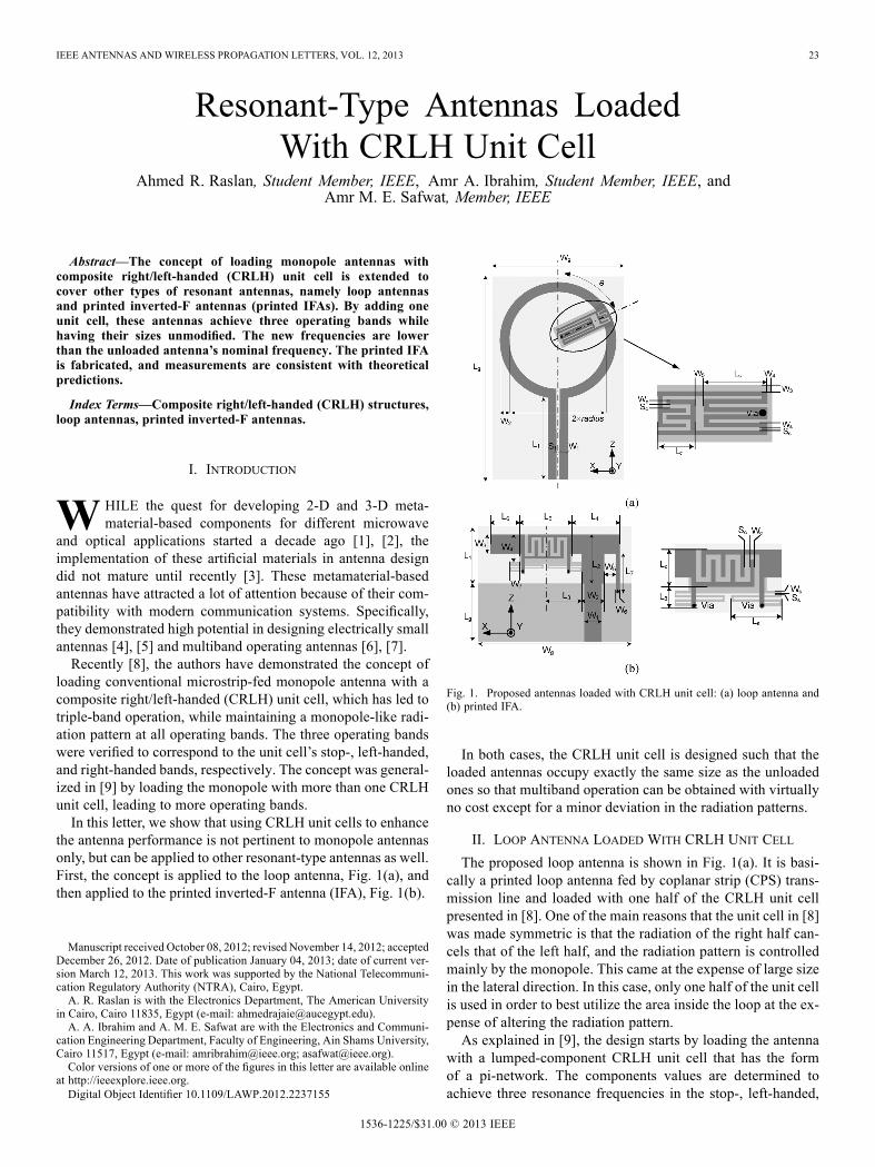
Fig. 1. Proposed antennas loaded with CRLH unit cell: (a) loop antenna and(b) printed IFA.
In both cases, the CRLH unit cell is designed such that theloaded antennas occupy exactly the same size as the unloadedones so that multiband operation can be obtained with virtuallyno cost except for a minor deviation in the radiation patterns.
II. LOOP ANTENNA LOADED WITH CRLH UNIT CELL
The proposed loop antenna is shown in Fig. 1(a). It is basi-cally a printed loop antenna fed by coplanar strip (CPS) trans-mission line and loaded with one half of the CRLH unit cellpresented in [8]. One of the main reasons that the unit cell in [8]was made symmetric is that the radiation of the right half can-cels that of the left half, and the radiation pattern is controlledmainly by the monopole. This came at the expense of large sizein the lateral direction. In this case, only one half of the unit cellis used in order to best utilize the area inside the loop at the ex-pense of altering the radiation pattern.As explained in [9], the design starts by loading the antenna
with a lumped-component CRLH unit cell that has the formof a pi-network. The components values are determined toachieve three resonance frequencies in the stop-, left-handed,
1536-1225/$31.00 © 2013 IEEE
24 IEEE ANTENNAS AND WIRELESS PROPAGATION LETTERS, VOL. 12, 2013
TABLE IDIMENSIONS OF THE ANTENNAS PRESENTED IN THIS LETTER (IN MILLIMETERS)
and right-handed bands, respectively. The dimensions of theinterdigital capacitor and meandered inductors are then ad-justed to achieve the same dispersion relation as that of thelumped-component counterpart.The loop antenna is designed on Rogers 5870 with substrate
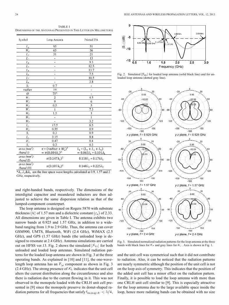
thickness of 1.57 mm and a dielectric constant of 2.33.All dimensions are given in Table I. The antenna exhibits twonarrow bands at 0.925 and 1.57 GHz, in addition to a wide-band ranging from 1.9 to 2.9 GHz. Thus, the antenna can coverGSM900, UMTS, Bluetooth, WiFi (2.4 GHz), WiMAX (2.5GHz), and GPS (1.57 GHz) bands (the unloaded loop is de-signed to resonate at 2.4 GHz). Antenna simulations are carriedout on HFSS ver.13. Fig. 2 shows the simulated for bothunloaded and loaded loop antennas. Simulated radiation pat-terns for the loaded loop antenna are shown in Fig. 3 at the threeoperating bands. As explained in [10] and [11], the one-wave-length loop antenna has an component as shown in Fig. 3(2.4 GHz). The strong presence of indicates that the unit cellalters the current distribution along the circumference and alsothere is radiation due to the current flowing in it. This was notobserved in the monopole loaded with the CRLH unit cell pre-sented in [9] since the monopole preserve its donut-shaped ra-diation patterns for all frequencies that satisfy ,
Fig. 2. Simulated for loaded loop antenna (solid black line) and for un-loaded loop antenna (dotted gray line).
Fig. 3. Simulated normalized radiation patterns for the loop antenna at the threebands with black lines for and gray lines for . Axis is shown in Fig. 1.
and the unit cell was symmetrical such that it did not contributeto radiation. Also, it can be noticed that the radiation patternsare nearly symmetric although the position of the unit cell is noton the loop axis of symmetry. This indicates that the position ofthe added unit cell has a minor effect on the radiation pattern.Finally, it is possible to load the loop antenna with more thanone CRLH unit cell similar to [9]. This is especially attractivefor the loop antenna due to the large available space inside theloop, hence more radiating bands can be obtained with no size
RASLAN et al.: RESONANT-TYPE ANTENNAS LOADED WITH CRLH UNIT CELL 25
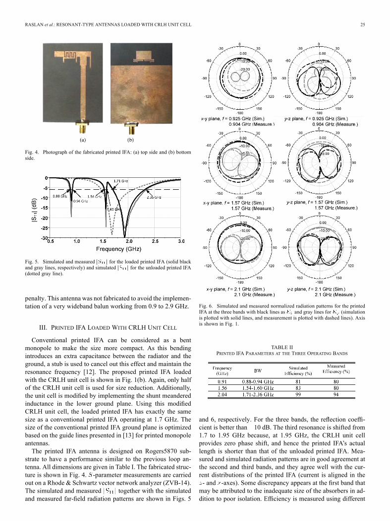
Fig. 4. Photograph of the fabricated printed IFA: (a) top side and (b) bottomside.
Fig. 5. Simulated and measured for the loaded printed IFA (solid blackand gray lines, respectively) and simulated for the unloaded printed IFA(dotted gray line).
penalty. This antenna was not fabricated to avoid the implemen-tation of a very wideband balun working from 0.9 to 2.9 GHz.
III. PRINTED IFA LOADED WITH CRLH UNIT CELL
Conventional printed IFA can be considered as a bentmonopole to make the size more compact. As this bendingintroduces an extra capacitance between the radiator and theground, a stub is used to cancel out this effect and maintain theresonance frequency [12]. The proposed printed IFA loadedwith the CRLH unit cell is shown in Fig. 1(b). Again, only halfof the CRLH unit cell is used for size reduction. Additionally,the unit cell is modified by implementing the shunt meanderedinductance in the lower ground plane. Using this modifiedCRLH unit cell, the loaded printed IFA has exactly the samesize as a conventional printed IFA operating at 1.7 GHz. Thesize of the conventional printed IFA ground plane is optimizedbased on the guide lines presented in [13] for printed monopoleantennas.The printed IFA antenna is designed on Rogers5870 sub-
strate to have a performance similar to the previous loop an-tenna. All dimensions are given in Table I. The fabricated struc-ture is shown in Fig. 4. -parameter measurements are carriedout on a Rhode & Schwartz vector network analyzer (ZVB-14).The simulated and measured together with the simulatedand measured far-field radiation patterns are shown in Figs. 5
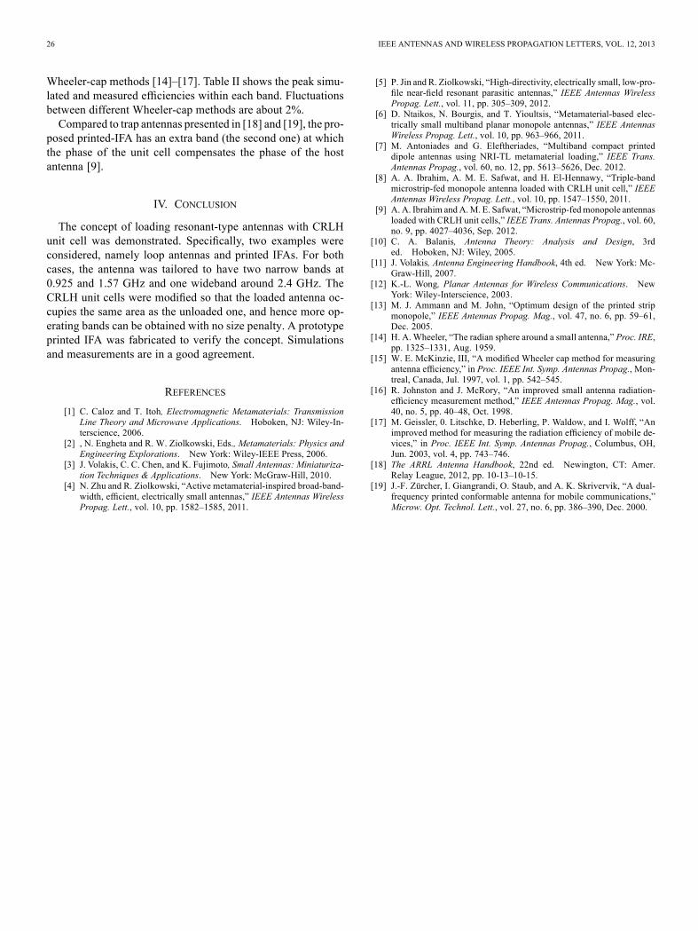
Fig. 6. Simulated and measured normalized radiation patterns for the printedIFA at the three bands with black lines as and gray lines for (simulationis plotted with solid lines, and measurement is plotted with dashed lines). Axisis shown in Fig. 1.
TABLE IIPRINTED IFA PARAMETERS AT THE THREE OPERATING BANDS
and 6, respectively. For the three bands, the reflection coeffi-cient is better than 10 dB. The third resonance is shifted from1.7 to 1.95 GHz because, at 1.95 GHz, the CRLH unit cellprovides zero phase shift, and hence the printed IFA’s actuallength is shorter than that of the unloaded printed IFA. Mea-sured and simulated radiation patterns are in good agreement atthe second and third bands, and they agree well with the cur-rent distributions of the printed IFA (current is aligned in the- and -axes). Some discrepancy appears at the first band thatmay be attributed to the inadequate size of the absorbers in ad-dition to poor isolation. Efficiency is measured using different
26 IEEE ANTENNAS AND WIRELESS PROPAGATION LETTERS, VOL. 12, 2013
Wheeler-cap methods [14]–[17]. Table II shows the peak simu-lated and measured efficiencies within each band. Fluctuationsbetween different Wheeler-cap methods are about 2%.Compared to trap antennas presented in [18] and [19], the pro-
posed printed-IFA has an extra band (the second one) at whichthe phase of the unit cell compensates the phase of the hostantenna [9].
IV. CONCLUSION
The concept of loading resonant-type antennas with CRLHunit cell was demonstrated. Specifically, two examples wereconsidered, namely loop antennas and printed IFAs. For bothcases, the antenna was tailored to have two narrow bands at0.925 and 1.57 GHz and one wideband around 2.4 GHz. TheCRLH unit cells were modified so that the loaded antenna oc-cupies the same area as the unloaded one, and hence more op-erating bands can be obtained with no size penalty. A prototypeprinted IFA was fabricated to verify the concept. Simulationsand measurements are in a good agreement.
REFERENCES
[1] C. Caloz and T. Itoh, Electromagnetic Metamaterials: TransmissionLine Theory and Microwave Applications. Hoboken, NJ: Wiley-In-terscience, 2006.
[2] , N. Engheta and R. W. Ziolkowski, Eds., Metamaterials: Physics andEngineering Explorations. New York: Wiley-IEEE Press, 2006.
[3] J. Volakis, C. C. Chen, and K. Fujimoto, Small Antennas: Miniaturiza-tion Techniques & Applications. New York: McGraw-Hill, 2010.
[4] N. Zhu and R. Ziolkowski, “Active metamaterial-inspired broad-band-width, efficient, electrically small antennas,” IEEE Antennas WirelessPropag. Lett., vol. 10, pp. 1582–1585, 2011.
[5] P. Jin and R. Ziolkowski, “High-directivity, electrically small, low-pro-file near-field resonant parasitic antennas,” IEEE Antennas WirelessPropag. Lett., vol. 11, pp. 305–309, 2012.
[6] D. Ntaikos, N. Bourgis, and T. Yioultsis, “Metamaterial-based elec-trically small multiband planar monopole antennas,” IEEE AntennasWireless Propag. Lett., vol. 10, pp. 963–966, 2011.
[7] M. Antoniades and G. Eleftheriades, “Multiband compact printeddipole antennas using NRI-TL metamaterial loading,” IEEE Trans.Antennas Propag., vol. 60, no. 12, pp. 5613–5626, Dec. 2012.
[8] A. A. Ibrahim, A. M. E. Safwat, and H. El-Hennawy, “Triple-bandmicrostrip-fed monopole antenna loaded with CRLH unit cell,” IEEEAntennas Wireless Propag. Lett., vol. 10, pp. 1547–1550, 2011.
[9] A. A. Ibrahim andA.M. E. Safwat, “Microstrip-fedmonopole antennasloaded with CRLH unit cells,” IEEE Trans. Antennas Propag., vol. 60,no. 9, pp. 4027–4036, Sep. 2012.
[10] C. A. Balanis, Antenna Theory: Analysis and Design, 3rded. Hoboken, NJ: Wiley, 2005.
[11] J. Volakis, Antenna Engineering Handbook, 4th ed. New York: Mc-Graw-Hill, 2007.
[12] K.-L. Wong, Planar Antennas for Wireless Communications. NewYork: Wiley-Interscience, 2003.
[13] M. J. Ammann and M. John, “Optimum design of the printed stripmonopole,” IEEE Antennas Propag. Mag., vol. 47, no. 6, pp. 59–61,Dec. 2005.
[14] H. A. Wheeler, “The radian sphere around a small antenna,” Proc. IRE,pp. 1325–1331, Aug. 1959.
[15] W. E. McKinzie, III, “A modified Wheeler cap method for measuringantenna efficiency,” in Proc. IEEE Int. Symp. Antennas Propag., Mon-treal, Canada, Jul. 1997, vol. 1, pp. 542–545.
[16] R. Johnston and J. McRory, “An improved small antenna radiation-efficiency measurement method,” IEEE Antennas Propag. Mag., vol.40, no. 5, pp. 40–48, Oct. 1998.
[17] M. Geissler, 0. Litschke, D. Heberling, P. Waldow, and I. Wolff, “Animproved method for measuring the radiation efficiency of mobile de-vices,” in Proc. IEEE Int. Symp. Antennas Propag., Columbus, OH,Jun. 2003, vol. 4, pp. 743–746.
[18] The ARRL Antenna Handbook, 22nd ed. Newington, CT: Amer.Relay League, 2012, pp. 10-13–10-15.
[19] J.-F. Zürcher, I. Giangrandi, O. Staub, and A. K. Skrivervik, “A dual-frequency printed conformable antenna for mobile communications,”Microw. Opt. Technol. Lett., vol. 27, no. 6, pp. 386–390, Dec. 2000.