rick van ‘t spijker - lmsc, lan/man standards committee … · · 2011-04-07rick van ‘t...
TRANSCRIPT

Multiple Systems Link Aggregation Control Protocol
Rick van ‘t Spijker Bachelor of Telecommunications
Dissertation Module
For
Master of Science ‐ Mobile and Distributed Computer Networks
Leeds Metropolitan University Innovation North
Student ID. 77071074
31 May 2010

Multiple Systems Link Aggregation Control Protocol
31 May 2010 Page 2

Multiple Systems Link Aggregation Control Protocol
Acknowledgements
This dissertation is written as part of the requirements for completion of the course “Master of Science in Mobile and Distributed Computer Networks” at the Leeds Metropolitan University. This dissertation would not be possible without: Professor Colin Pattinson. My supervisor who guided me throughout the project and whose remote support helped me set the framework for the research and dissertation document. Vosko Networking. My company and all my colleagues, who gave me the time and opportunity to complete this course. Erik Geerars. Manager Systems Engineering at Avaya and former employee of Nortel Enterprise in the Netherlands, who draw my attention to this course and provided me with a recommendation letter. My wife Wilma and my children who supported me in many ways during the course. The Lord in heaven for giving me the talent to fulfil this course and supporting me in every way.
31 May 2010 Page 3

Multiple Systems Link Aggregation Control Protocol
Abstract The availability of the data network in current Enterprises is getting more and more crucial due to the fact that more types of applications are connected. Loss of connections and long failover times must be avoided to support all these types of applications. The objective of this dissertation is to develop a protocol to enhance the standard for link aggregation as defined by the Institute of Electrical and Electronics Engineers (IEEE) in the IEEE802.1AX™ standard, to support aggregation of links across multiple systems. The proposed protocol is called the Multiple Systems Link Aggregation Control Protocol (MSLACP). It is intended to propose MSLACP to the IEEE802.1AX™ working group for standardisation. The MSLACP process is subdivided in several phases an individual system can be in. These phases are specified in flowcharts that show the steps of a specific phase. The flowcharts and corresponding detailed descriptions are part of the research in defining the synchronisation needs and are used for evaluating the MSLACP behaviour. These synchronisation needs are translated to the MSLACP version 1 protocol. The main conclusion after evaluating MSLACP is that there are multiple benefits of this proposal in respect to the IEEE802.1AX™ standard and proprietary solutions. Whether or not MSLACP is viable depend on the adoption by vendors and their priority in offering a standard solution to aggregate links from different systems.
31 May 2010 Page 4
Multiple Systems Link Aggregation Control Protocol
Table of Contents 1 Introduction ................................................................................................. 8
1.1 General Introduction ............................................................................................................... 8
1.2 Layered Enterprise Network Design ....................................................................................... 9
1.3 Dangers of Network Redundancy ......................................................................................... 10
1.4 Network Redundancy Mechanisms ...................................................................................... 11
1.5 Proprietary link aggregation solutions .................................................................................. 12
1.5.1 Virtual Switching System (VSS) by Cisco ....................................................................... 12
1.5.2 Virtual PortChannels (vPC) by Cisco .............................................................................. 12
1.5.3 Split Multilink Trunking (SMLT) by Avaya (formally Nortel) ......................................... 12
1.5.4 Virtual Chassis (VC) by Juniper ...................................................................................... 12
1.5.5 Multi‐Chassis Link Aggregation Group (MC‐LAG) by Alcatel‐Lucent ............................ 13
1.6 Research IEEE802.1AX™ standard enhancement ................................................................. 14
1.6.1 Research Method .......................................................................................................... 14
2 Multiple Systems Link Aggregation Protocol (MSLACP) ............................. 15 2.1 Introduction .......................................................................................................................... 15
2.2 MSLACP Basic Assumptions .................................................................................................. 17
2.2.1 Compatibility ................................................................................................................. 17
2.2.2 Link Aggregation Group responsibility .......................................................................... 17
2.2.3 Synchronisation ............................................................................................................. 18
2.2.4 MSLACP specific configuration parameters .................................................................. 19
2.2.5 Predefined limitations ................................................................................................... 19
2.3 MSLACP Phase Flowcharts .................................................................................................... 20
2.3.1 Multiple Systems Link Aggregation Group Start‐up ...................................................... 21
2.3.2 Master Election ............................................................................................................. 23
2.3.3 Master Function ............................................................................................................ 26
2.3.4 Backup Master Function ............................................................................................... 31
2.3.5 Master Change .............................................................................................................. 35
2.3.6 Slave Function ............................................................................................................... 37
2.4 MSLACP protocol .................................................................................................................. 41
2.4.1 Protocol Header ............................................................................................................ 42
2.4.2 Master Query packet .................................................................................................... 44
2.4.3 Master Query Reply packet........................................................................................... 45
2.4.4 Key Error Reply packet .................................................................................................. 46
2.4.5 Backup Master Query packet ........................................................................................ 47
2.4.6 Backup Master Query Reply packet .............................................................................. 48
2.4.7 Query Acknowledgement packet .................................................................................. 49
31 May 2010 Page 5

Multiple Systems Link Aggregation Control Protocol
2.4.8 Master Claim packet ..................................................................................................... 50
2.4.9 Backup Master Claim packet ......................................................................................... 51
2.4.10 Master Hello packet ...................................................................................................... 52
2.4.11 Backup Master Hello packet ......................................................................................... 53
2.4.12 Slave Hello packet ......................................................................................................... 55
2.4.13 MSLAG Configuration packet ........................................................................................ 56
2.4.14 MSLAG Partner Information packet .............................................................................. 61
2.4.15 MSLAG FDB Synchronisation packet ............................................................................. 63
2.4.16 Master Synchronisation packet .................................................................................... 65
2.4.17 Master Change packet .................................................................................................. 67
2.4.18 Master Change Acknowledgement packet ................................................................... 68
2.5 MSLACP constraints .............................................................................................................. 69
3 MSLACP Design Guidelines ......................................................................... 70 3.1 IEEE802. 1AX™ guidelines ..................................................................................................... 70
3.2 Physical guidelines ................................................................................................................ 70
3.3 Configuration guidelines ....................................................................................................... 71
4 Evaluation and Results ............................................................................... 72
5 Conclusion and Future Work ...................................................................... 75
6 References ................................................................................................. 77
31 May 2010 Page 6

Multiple Systems Link Aggregation Control Protocol
Table of Figures Figure 1: Four layer network architecture ............................................................................................. 9 Figure 2: MSLACP block diagram ......................................................................................................... 16 Figure 3: MSLACP Link Aggregation Group Start‐up ........................................................................... 21 Figure 4: Master Election ..................................................................................................................... 23 Figure 5: Master Function .................................................................................................................... 26 Figure 6: Backup Master Function ....................................................................................................... 31 Figure 7: Master Change Process ......................................................................................................... 35 Figure 8: Slave Function ....................................................................................................................... 37 Figure 9: MSLACP common header format ......................................................................................... 42 Figure 10: Master Query packet format .............................................................................................. 44 Figure 11: Master Query Reply packet format .................................................................................... 45 Figure 12: Key Error Reply packet format............................................................................................ 46 Figure 13: Backup Master Query packet format ................................................................................. 47 Figure 14: Backup Master Query Reply packet format ....................................................................... 48 Figure 15: Query Acknowledgement packet format ........................................................................... 49 Figure 16: Master Claim packet format ............................................................................................... 50 Figure 17: Backup Master Claim packet format .................................................................................. 51 Figure 18: Master Hello packet format ............................................................................................... 52 Figure 19: Port Status field ................................................................................................................... 53 Figure 20: Backup Master Hello packet format .................................................................................. 54 Figure 21: Forced Port State byte ........................................................................................................ 57 Figure 22: Basic Configuration packet format ..................................................................................... 58 Figure 23: LACPDU Configuration packet format ................................................................................ 60 Figure 24: MSLAG Partner Information packet format ....................................................................... 62 Figure 25: MSLAG FDB Synchronisation packet format ...................................................................... 64 Figure 26: Master Synchronisation packet format .............................................................................. 66 Figure 27: Master Change packet format............................................................................................ 67 Figure 28: Master Change Acknowledgement packet format ............................................................ 68 Figure 29: MSLACP design example ..................................................................................................... 71
31 May 2010 Page 7

Multiple Systems Link Aggregation Control Protocol
1 Introduction
1.1 General Introduction Until a few years ago, the data network in large Enterprises was primarily used for traditional applications like office‐related applications for word processing, spreadsheet applications, presentations, e‐mail and calendar and file sharing. Currently the network in Enterprise environments must be fully converged to support different applications. As Rungta and Ben‐Shalom (2006) wrote, a fully converged network in the Enterprise must be ready to service Data, Voice, Video, Wireless (or Mobility) and Security. In current Enterprise networks also Unified Communications, Telecom and Storage are being serviced. These different applications have different demands regarding security, quality of service (QoS), network availability and network recovery in a failure scenario. The research in this dissertation focuses on this last demand, network recovery in a failure scenario. For the network to be able to recover from a failure scenario, the network designer has to consider redundant connections to one or multiple devices in the network. At the same time, the maximum failover times in case of a fault scenario must be considered, based on the applications that are used on the network. Where traditional application data is generally lenient when it comes to these failover times, voice and video traffic demands a failover within hundreds of milliseconds. To meet these failover times for redundant connections, several solutions are available, including vendor proprietary solutions and solutions that are standardized by international organisations. The international organisation Institute of Electrical and Electronics Engineers (IEEE) published the IEEE802.1AX™ standard for link aggregation (2008b) that describes the aggregation of multiple physical links to one virtual link. Failure of one of the physical links is detected and traffic is rerouted to another link within a second. This standard though is intended to aggregate only physical links that are part of the same system. It would be desirable if physical links across multiple systems can be aggregated. This to avoid a scenario where a complete system fails due to an external problem (e.g. power failure or an incident in the equipment room like a fire or flooding). Different vendors have proprietary solutions to aggregate physical links across different systems. Downside of proprietary solutions is the lack of interoperability. To be able to aggregate physical links across different systems, produced by different vendors, the objective of this dissertation is to enhance the IEEE802.1AX™ standard to support aggregation of physical links across multiple systems. The research includes the following elements: • Definition of the interface between different systems across which the physical links are to be
aggregated. • Determine the required behaviour of the solution. • Develop the synchronisation protocol that is used for communication between the different
systems. • Evaluate the behaviour of the solution in operational and fault scenarios.
31 May 2010 Page 8

Multiple Systems Link Aggregation Control Protocol
1.2 Layered Enterprise Network Design As mentioned before, in large Enterprises the data network becomes more and more crucial due to the broader range of applications. Where a network used to be a single connection between several clients and a single server using a hub or switch, nowadays large Enterprise networks are designed using a three or four layer architecture. These layers are: • Core layer ‐ Multiple core switches using standard Ethernet or Service Provider (SP) techniques
like Metro Ethernet (ME) or Multiprotocol Label Switching (MPLS). • Distribution layer ‐ Access and server distribution switches connected to the core layer using
redundant physical connections. • Server layer – Data centre network using either a single server switch (stackable or chassis
based), an end‐of‐row concept where all servers in a row of server racks are connected to a server switch (stackable of chassis based) or a top‐of‐rack concept where in each server rack one or two stackable switches are used for local patching of servers.
• Access layer – Stackable or chassis based switches for connecting workstations and other user equipment.
A four layer architecture is depicted in Figure 1.
Figure 1: Four layer network architecture
31 May 2010 Page 9

Multiple Systems Link Aggregation Control Protocol
1.3 Dangers of Network Redundancy Companies totally rely on the availability of the network, and Single Points of Failure (SPOF) are limited. Redundancy is introduced in all Open Systems Interconnection (OSI) layers. For instance server applications and databases are installed on two or more physical or virtual platforms and OSI layer 4 to layer 7 load balancing is introduced with application switches, to provide for an ‘always available’ server infrastructure. On physical networking equipment, redundant connections are used to limit the physical SPOFs. These are used between servers and network switches or with interconnections between network switches, as shown in Figure 1. In a redundant network design according to the described layered architecture with access switches redundantly connected to one or more core or distribution switches, a physical loop in the network is created. According to Ethernet standard IEEE802.3™ as defined by the Institute of Electrical and Electronics Engineers (IEEE, 2008a), a loop in the network (which is created in a physical redundant design) must be avoided. The reason a loop must be avoided is found in the behaviour of data traffic over an Ethernet infrastructure. Basic data traffic can be classified as one of three types: Unicast: Traffic destined for a single device. Multicast: Traffic destined for multiple devices. Broadcast: Traffic destined for all devices. Both on OSI layer 2 (data link layer) and layer 3 (network layer), specific address spaces are reserved for all three types. For layer 2 traffic the 48‐bit Media Access Control (MAC) address defines the traffic type. The layer 2 data is unicast when the least significant bit of the most significant byte of the MAC address is set to ‘0’. The layer 2 data is multicast when this bit is set to ‘1’. The layer 2 data is broadcast when all bits of the 48‐bit MAC address is set to ‘1’. All three types of traffic are treated differently by the networking equipment. Or rather by the network switches since the ‘old’ networking equipment like hubs or repeaters treated the three forms of traffic the same way. When a switch receives data traffic, it updates its forwarding database with the binding of source unicast MAC address and physical port. When a unicast data packet is received on a switch port, the destination MAC address is looked up in the forwarding database and the packet is forwarded out the corresponding physical port. Unknown traffic, multicast traffic and broadcast traffic is not registered in the forwarding database of the switch and will be flooded out all ports in the layer 2 domain of the switch. Due to this behaviour, when a physical loop in the network is present, this unknown, multicast and broadcast traffic will be flooded on every port of every switch within the layer 2 domain, and will indefinitely be forwarded. This is referred to as a broadcast storm. Each standard Ethernet switch has to assess each packet entering the switch and in a case of a broadcast storm, the Central Processing Unit (CPU) will be overloaded.
31 May 2010 Page 10

Multiple Systems Link Aggregation Control Protocol
1.4 Network Redundancy Mechanisms
To avoid this broadcast storm but still be redundant, protocols like the Spanning Tree Protocol (STP; IEEE802.1D™) or the extension Rapid Spanning Tree Protocol (RSTP; IEEE802.1w™), as incorporated in the IEEE802.1D™‐2004 standard (IEEE, 2004), are used. STP and RSTP break the loop by blocking the appropriate physical ports. These ports are not used for data forwarding anymore and are only sending Bridge Protocol Data Unit (BPDU) packets for controlling the (R)STP protocol. When a problem occurs in the redundant connections (e.g. failure of the physical link), the protocol will detect this and will set the blocking port in forwarding mode. Since a broadcast storm only occurs in an OSI layer 2 domain, an OSI layer 3 solution using routing protocols Open Shortest Path First (OSPF) and Virtual Router Redundancy Protocol (VRRP) can also be used to avoid a loop but still have redundant connections. Downside to these solutions is the recovery time needed when an incident occurs. With STP the recovery time takes up to 60 seconds and RSTP approximately 8 seconds, depending on the type of incident and the network topology. In an OSI layer 3 solution the recovery times can be as little as a few seconds, but with a layer 3 solution there is no possibility for an OSI Layer 2 Virtual Local Area Network (VLAN) to span multiple access switches. Another option to avoid broadcast storms is to bundle multiple physical connections to one logical link. There are several vendors offering this solution with a proprietary mechanism, but it is also standardised in the IEEE802.1AX™ standard for Link aggregation (IEEE, 2008b). This standard was formally defined in the IEEE802.3™‐2005 Ethernet standard clause 43 as IEEE802.3AD™, but has been moved to the (standalone) 802.1™ series of standards in 2008. Using this standard or one of the proprietary mechanisms of bundling physical ports, a layer 2 VLAN can span multiple access switches, interconnected with multiple physical links called a Link Aggregation Group (LAG), without forming a loop. But since IEEE802.1AX™ Link Aggregation is only defined for a single system, the redundancy is limited to a point to point connection between two devices. As Bocci, Cowburn and Guillet (2008) also mention, a complete system failure on one end will bring down the LAG. In large Enterprise environments, the core or distribution layer of the network is set up using multiple switches, placed in different locations. This means that redundant connections from an access layer ideally connect to multiple switches in the distribution or core layer. The standard as defined in IEEE802.1AX™ doesn’t provide for this. One conclusion of Van ‘t Spijker (2009) is that when Metro Ethernet (ME) or Multi Protocol Label Switching (MPLS) is used in the core of an Enterprise network, challenges exist in redundant connections between these core technologies and the standard Ethernet Access layer or Data Centre. These challenges particularly exist when layer 2 Virtual Private Networks (VPNs) are used. The objective for this dissertation is to address these challenges and investigate the possibility to enhance the international standard IEEE802.1AX™ to support link aggregation groups spanning two or multiple systems.
31 May 2010 Page 11

Multiple Systems Link Aggregation Control Protocol
1.5 Proprietary link aggregation solutions Different vendors developed mechanisms to address the need for aggregating links across multiple systems. Currently some proprietary mechanisms for aggregating physical port groups on multiple switches are: • Virtual Switching System (VSS) by Cisco • Virtual PortChannels (vPC) by Cisco • Split Multilink Trunking (SMLT) by Avaya (formerly Nortel) • Virtual Chassis (VC) by Juniper • Multi‐Chassis Link Aggregation Group redundancy (MC‐LAG) by Alcatel‐Lucent These mechanisms are developed by different vendors and are all based on, or are compatible with IEEE802.1AX™. In this chapter a brief description of these proprietary mechanisms is discussed.
1.5.1 Virtual Switching System (VSS) by Cisco As described by Cisco in a white paper (Cisco Systems, 2006), the VSS technology is based on a concept to interconnect the switching backplanes of two Catalyst 6500 chassis’ using a Virtual Switch Link (VSL), and merge these two chassis’ into a single, logically managed entity. Ethernet ports on both chassis’ can be aggregated using the Cisco proprietary mechanism EtherChannel or using the IEEE802.1AX™ Link Aggregation standard. Since the mechanism is based on merging two chassis’, local redundancy within one chassis is limited to dual power supplies, fan trays and I/O modules.
1.5.2 Virtual PortChannels (vPC) by Cisco In the Cisco Nexus series of switches, the virtual PortChannel functionality is introduced. Unlike the VSS concept of Cisco, vPC doesn’t merge two chassis’ into one single managed entity. As described by Cisco (2009), two Nexus switches form a vPC pair of switches, interconnected by a vPC peer link. A logical link is created between the two peers for keep alive purposes. This link can also run over an out‐of‐band management network. For aggregation of ports, several member ports on the two peers are configured in the vPC. Unlike the VSS concept, local redundancy per chassis (including CPU functionality) is fully supported. The vPC functionality is currently available in both chassis’ (Nexus 7000) and standalone switches (Nexus 5000).
1.5.3 Split Multilink Trunking (SMLT) by Avaya (formally Nortel) SMLT is an evolution of Nortel’s Multilink Trunking (MLT) mechanism for aggregating Ethernet ports on a single switch. Where in MLT the aggregated ports are located on one switch or one module in a chassis, in SMLT these ports can be located on two different switches or chassis’ in different locations. An SMLT pair of switches is interconnected using an Inter Switch Trunk (IST), which is used for synchronising the switches databases (Nortel Networks, 2005). Unlike the Cisco VSS mechanism, SMLT switches are independently managed switches and can have local redundancy of CPU modules. The SMLT functionality is currently available for several Ethernet Routing Switch (ERS) types, including chassis’ (ERS8600 and ERS8300), standalone (ERS1600) and stackable switches (ERS5000 series).
1.5.4 Virtual Chassis (VC) by Juniper Juniper Networks has, like a lot of vendors, developed stackable switches, supporting link aggregation of links across different units in the stack. As described by Juniper in the Virtual Chassis implementation guide (2009), in the VC solution the stacking ports, usually interconnected with dedicated short‐reach (up to five or ten meters) cables, can also be 1 or 10 Gigabit Ethernet fibre
31 May 2010 Page 12

Multiple Systems Link Aggregation Control Protocol
ports. This gives the advantages of stacking (e.g. single management, redundant routing engines and single forwarding table), but the different units can be placed in different locations, multiple kilometres apart. Ports that are part of a single Link Aggregation Group (LAG) can be on either unit in the stack. Currently VC is available in the EX4200 series of switches.
1.5.5 Multi‐Chassis Link Aggregation Group (MC‐LAG) by Alcatel‐Lucent In MC‐LAG as described by Alcatel‐Lucent (2008) the IEEE802.1AX™ standard is implemented across multiple chassis’ using the standby feature as described in the standard (IEEE, 2008b). The links on only one chassis of an MC‐LAG pair are actively used for data throughput, while the links on the other chassis are standby. Between the two MC‐LAG peers, a redundant synchronisation path must be present on which a MC‐LAG Control Protocol is defined. This control protocol is used to exchange basic LAG parameters, the weights of the sub‐group and the number of connected links per peer. Using this weight and the link count, the two systems decide which group of ports (located on one of the two chassis’) are used as active links. The MC‐LAG mechanism is currently available on the 7450 Ethernet Services Switch series and the 7710 and 7750 Service Router series.
31 May 2010 Page 13

Multiple Systems Link Aggregation Control Protocol
1.6 Research IEEE802.1AX™ standard enhancement
The different proprietary solutions as described in chapter 1.5 differ on several areas and all have their advantages and disadvantages. The objective of MSLACP is to develop a protocol to enhance the standard for link aggregation as defined by the Institute of Electrical and Electronics Engineers (IEEE) in the IEEE802.1AX™ standard, to support aggregation of links across multiple systems from different vendors, without impacting the proprietary advantages of these individual systems.
1.6.1 Research Method The research has been done in different stages. In this dissertation paper each stage (with exception of the first stage) is discussed in a separate chapter. The different stages are: • Gathering and studying reference material from the standards organisations and different
vendors. During this stage the framework for the distributed link aggregation mechanism has been set and different ways to address the communication and synchronisation needs have been examined.
• Defining some crucial questions that needed to be answered in order to define the principles the protocol has to meet. These principles are described in chapter 2.2.
• Formulate different flowcharts for the different phases of the systems. These flowcharts are also used to test the MSLACP protocol whether it meets the defined principles. The flowcharts are described in chapter 2.3.
• Design the protocol needed for the communication and synchronisation between the different systems. The different protocol packet types are described. In chapter 2.4 the MSLACP protocol format is described.
• Determining the design guidelines of the MSLACP protocol (chapter 3) and evaluate the protocol when implemented using these guidelines (chapter 4).
• Propose next steps for additional research of the MSLACP protocol (chapter 5).
31 May 2010 Page 14

Multiple Systems Link Aggregation Control Protocol
31 May 2010 Page 15
2 Multiple Systems Link Aggregation Protocol (MSLACP)
2.1 Introduction As described in the IEEE802.1AX™ standard (IEEE, 2008b), the link aggregation sub layer comprise the following functions: • Aggregator
o Frame Distribution o Frame Collection o Aggregator Parser/Multiplexers
• Aggregation Control • Control Parser/Multiplexers A system can have multiple aggregators, each with a unique Group ID. Physical ports can be assigned to (at most) a single aggregator. The Link Aggregation Control (LAC) function holds the information of the aggregators in a system and there is only one LAC in a system. The LAC “is responsible for determining which links may be aggregated, aggregating them, binding the ports within a System to an appropriate Aggregator, and monitoring conditions to determine when a change in aggregation is needed” (IEEE, 2008b, p. 11). The objective for the MSLACP research is to develop and describe a solution where multiple systems can share the IEEE802.1AX™ Link Aggregation process, and form a Link Aggregation Group (LAG) with physical ports on multiple systems. The objective of this dissertation is to develop a protocol to enhance the standard for link aggregation as defined by the Institute of Electrical and Electronics Engineers (IEEE) in the IEEE802.1AX™ standard, to support aggregation of links across multiple systems. The proposed protocol is called the Multiple Systems Link Aggregation Control Protocol (MSLACP). It is intended to propose MSLACP to the IEEE802.1AX™ working group for standardisation. Since an MSLACP system must be compatible with the standard, no changes in the LACP process or local traffic distribution mechanisms are made and the principles of the LACP protocol stay intact. When a Link Aggregation Group (LAG) or aggregator must span multiple systems, the LAC function must be synchronised or shared between these systems. The MSLACP proposal can be depicted as in Figure 2

Multiple Systems Link Aggregation Control Protocol
Figure 2: MSLACP block diagram
31 May 2010 Page 16

Multiple Systems Link Aggregation Control Protocol
2.2 MSLACP Basic Assumptions
The first part of the project is to decide on some basic assumptions. These assumptions are used to set the framework for the MSLACP mechanism. Assumptions in the following areas are defined: • Compatibility • Link Aggregation Group responsibility • Synchronisation • MSLACP specific configuration parameters • Predefined limitations
2.2.1 Compatibility Looking at the networking vendors as described in chapter 1.5, all of these offer, beside a proprietary mechanism, support for the Link Aggregation Control Protocol (LACP) as described in the IEEE802.1AX™ standard. This protocol support is implemented to be able to set up a Partner connection with third party devices like servers and therefore potentially offer a larger market share. Because of the extensive availability of devices with LACP support, not being compatible to the standard will lead to a lack of adoption by the hardware vendors. So when MSLACP is implemented, it must be fully compatible to the existing IEEE802.1AX™ standard. Compatibility with proprietary solutions is not part of the protocol. The objective is to enhance the IEEE standard and therefore no vendor‐specific compatibility will be part of the research. When a proprietary solution is compatible with the IEEE802.1AX™ standard, this solution will automatically also be compatible with the MSLACP mechanism. To prevent for a network loop in a standard Link Aggregation implementation where links from different Link Aggregation Groups or individual links are connected, to happen, the IEEE802.1AX™ standard has introduced the System ID and operational key. A Partner system only aggregates links that are connected to ports that send identical System ID and operational key values in the LACPDU packets. In MSLACP, the same prevention is used.
2.2.2 Link Aggregation Group responsibility During the development phase, two methods for the design have been considered: different autonomous systems or a Master‐Slave based design. While in the IEEE802.1AX™ standard a single LAC function is used to control the Link aggregation groups, a single Multiple Systems Link Aggregation Control (MSLAC) function is used as assumption for the MSLACP research, which implies a Master‐Slave design. To limit the synchronisation traffic though, the LAC function of remote systems is used for local forwarding decisions without having to consult the Master system. With a Master/Slave design, introduction of a SPOF in the system must be avoided. The Master LAC function must therefore be redundant and a Master election process between the different systems must be implemented to provide for the availability of a Master system in all circumstances. This redundant Master system is called the Backup Master system and is part of the MSLACP research. In a failure situation not only redundancy of the Master functionality must be provided, also the impact on operational data traffic has to be part of the research. When using link aggregation, a failed link has limited impact on data forwarding since the traffic will be rerouted using another link in the aggregation group. In the MSLACP design, the impact of a failing system (Master or Slave) on operational data traffic must also be minimized. Failover of a Master system therefore has to be done in the background of the link aggregation process and the local LAC on all systems must provide for non‐disruptive data forwarding, with exception of links attached to the failed system.
31 May 2010 Page 17

Multiple Systems Link Aggregation Control Protocol
2.2.3 Synchronisation As shown in Figure 2, there is an MSLAC synchronisation link between the MSLACP systems. The use of dedicated MSLACP synchronisation links depends on the impact of a broken synchronisation link on which the MSLACP systems must synchronize forwarding information (data plane) and configuration information (control plane). When the synchronization is lost, systems will be autonomous and will group local ports that are configured in the MSLAG, what might result in a looped network. To address this, query packets and master failover is needed. Also to be able to have more than two systems forming an MSLAG, a broadcast domain (layer 2 VLAN) for MSLACP packets must be available. Assumption is that the use of dedicated links is no obligation, but is recommended. Configuration of an MSLACP system does require the configuration of synchronisation ports (and optionally the synchronisation layer 2 VLAN) additionally to ports that are used for link aggregation. Additional consideration in the configuration of the synchronisation port is the behaviour of the dataflow in case of a failed Partner link. When a Partner device is connected with two links, a failed Partner link will result in a single attached device to one of the MSLACP systems, so data forwarding between different MSLACP systems must be provided. When the VLANs configured on the MSLAG are also configured on the synchronisation link, there is always forwarding possible to single attached stations. As Avaya (formerly Nortel) describes in the ERS8600 design guidelines (Nortel Networks, 2009), in a well designed network the synchronisation link usually only forwards synchronisation traffic. In case of a single attached station though, traffic is forwarded on the synchronisation link. This link should therefore be at least the same speed or bandwidth as the attached stations or partner systems. Considering this, the synchronisation link is either a direct redundant connection with multiple VLANs or a Layer 2 VLAN across a (preferably redundant) switched network. As mentioned, synchronisation of data plane and control plane information between MSLACP systems is done on MSLACP synchronisation ports. The protocol that is used for this synchronisation has to be defined. Since MSLACP is compatible to the standard, synchronisation of LACP Partner information as defined in the IEEE802.1AX™ standard is done in Link Aggregation Control Protocol Data Units (LACPDU). This protocol is a so called ‘slow protocol’ which indicates that LACPDU’s are sent in a maximum rate of 10 frames per one‐second period (IEEE, 2008a, p. 509), and therefore cannot be used for synchronization of data plane information. There are two options: use an existing protocol or develop a new protocol. When an existing protocol is used, adoption of MSLACP is more obvious. This because in current systems protocol support is often done in hardware to increase the throughput of switches. When support in hardware is available, packets can be forwarded based on information available on port level, while for protocols not supported in hardware the forwarding decision is done by a central CPU of a switch. The synchronisation protocol that is used must be developed to transport any type of information using ‘type‐length‐value’ (TLV) elements. This way it can be used to synchronize both control plane and data plane information. Some existing protocols that use TLV fields are: • Link Layer Discovery Protocol (LLDP; IEEE802.1AB™) (IEEE, 2005). • Operations, Administration, and Maintenance PDU’s (OAMPDU) (IEEE, 2008a, section 5). • Intermediate system to intermediate system (IS‐IS; ISO/IEC 10589:2002) (ISO/IEC, 2002).
31 May 2010 Page 18

Multiple Systems Link Aggregation Control Protocol
When a new protocol is used though, the synchronisation of both data plane and control plane information is not limited to the characteristics of an existing protocol. Also since MSLACP uses a central controller function, MSLACP synchronisation packets always have to be examined by the CPU of a switch and cannot be offloaded in hardware. Due to this behaviour, the MSLACP protocol will not use an existing protocol and development of a synchronisation protocol is part of the research. As mentioned before, the information that is synchronized between all systems in an MSLAG is Control Plane information and Data Plane information. Control Plane information: Across the different Aggregation Control Units, configuration information must be identical. To control this, configuration control frames must be sent on a regular basis. Besides the regular updates, changes must trigger the exchange of control frames. Different Control Plane packets for MSLACP are: • Query packets. At initial boot to discover existing MSLACP systems for a particular MSLAG. • Master election. At activation of an MSLAG when no Master system is responding to the query
and triggered when the elected Master system has no more active ports in a group. • Number of locally attached ports in an MSLAG (Master system must maintain the locally defined
maximum). • Hello packets to determine whether the neighbouring systems are still present.
Common control plane information per synchronisation packet consist of: • Link Aggregation Group ID • System ID
Data Plane information Since MSLACP is positioned in the OSI Layer 2 protocol layer, only layer 2 data plane information needs to be synchronized. For a layer 2 switch this means: • Forwarding Database (MAC address ‐ physical or virtual port binding). • Availability of physical ports that are part of the MSLAG.
2.2.4 MSLACP specific configuration parameters During the development of MSLACP, configuration parameters are defined. To limit the number of specific parameters, MSLACP uses mainly information that is also required in the IEEE802.1AX™ standard. Reason to do this is the fact that most information is used in communicating with IEEE802.1AX™ LAG Partner systems. For identification purposes and to make sure no malicious system is part of the MSLAG, per system an MSLAG ID and MSLAG Key is required. MSLACP depends on the availability of external network devices. For proper and predictable network behaviour, there need to be design guidelines for the implementation of MSLACP. These guidelines include both physical and parametric configuration of the systems, and recommended configurations for the synchronisation network.
2.2.5 Predefined limitations Target is to not limit the number of systems that are part of an MSLAG. This implies the need of a Master, Backup Master and possible Slave systems. In practice, aggregating links across more than four systems will be unlikely, but the assumption is that there is no limit. Also the number of links that is part of an MSLAG is not limited. When a systems implementation though limits the number of links for any reason, this must be detected and MSLACP must act accordingly.
31 May 2010 Page 19

Multiple Systems Link Aggregation Control Protocol
2.3 MSLACP Phase Flowcharts
To make the MSLACP solution clear and to determine in which condition synchronization traffic is needed, the solution is represented in different flowcharts, one for each phase of the MSLACP process. Using these, the different steps and responsibilities of the individual systems are made clear. Each phase of the process is then described to clarify the synchronisation process and to identify the different MSLACP packets needed. Inevitably this means the following sections with the detailed process descriptions are short, since each relates to one element of the flowchart. However this level of detail is necessary for the completeness of the discussion and evaluation. The different phases of the MSLACP solution are: • Link Aggregation Group Start‐up • Master Election • Master Function • Backup Master Function • Master Change • Slave Function Since the systems that are part of an MSLAG are not the same for all groups, the flowcharts are intended to be by group and not by system. A single system with multiple groups can therefore have multiple functions.
31 May 2010 Page 20

Multiple Systems Link Aggregation Control Protocol
2.3.1 Multiple Systems Link Aggregation Group Start‐up At initial start of an MSLAG, the start function of the system must be defined. The flowchart for this process is shown in Figure 3.
Figure 3: MSLACP Link Aggregation Group Start‐up Send MSLAG Master Query packets During this step the system sends out Master Query packets. Since the system has no knowledge of other systems, the query is sent using a layer 2 multicast packet on the synchronisation VLAN. As the group is not activated on the local system, the packet rate of the Master Query can be once per second. In this query packet the following information is required: • MSLAG ID • MSLAG Key • Local System ID The local System ID will typically be the System ID as described in the LACP standard. The definition of the System ID as described in the standard (IEEE, 2008b, p.24) is: The globally unique identifier used to identify a System shall be the concatenation of a globally administered individual MAC address and the System Priority. The MAC address chosen may be the individual MAC address associated with one of the ports of the System. Where it is necessary to
31 May 2010 Page 21

Multiple Systems Link Aggregation Control Protocol
perform numerical comparisons between System Identifiers, each System Identifier is considered to be an eight octet unsigned binary number, constructed as follows: a) The two most significant octets of the System Identifier comprise the System Priority. The
System Priority value is taken to be an unsigned binary number; the most significant octet of the System Priority forms the most significant octet of the System Identifier.
b) The third most significant octet of the System Identifier is derived from the initial octet of the MAC address; the least significant bit of the octet is assigned the value of the first bit of the MAC address, the next most significant bit of the octet is assigned the value of the next bit of the MAC address, and so on. The fourth through eighth octets are similarly assigned the second through sixth octets of the MAC address
The MSLAG Master Query packet is described in chapter 2.4.2. Timer Wait for MSLAG (Master) Query Reply After sending a maximum of three query packets, the system will wait for 1 second for a Master Query Reply. This reply will only be send by the MSLAG Master and is a unicast packet. The information in the Query Reply is: • MSLAG ID • MSLAG Key • Local System ID • MSLAG System ID When a Master Query Reply is received, a Query Acknowledgement (chapter 2.4.7) will be sent to the Master system. The Master Query Reply packet is described in chapter 2.4.3. MSLAG Key Error Reply? When the locally configured MSLAG Key is incorrect, the MSLAG Master will send a MSLAG Key Error Reply packet. This packet will not contain any further MSLAG information, except for the MSLAG Group ID. The MSLAG Key Error Reply packet is described in chapter 2.4.4. Start Master Election Process Immediately after receipt of a Master Query Reply packet, or when the wait period is passed and no MSLAG Key Error Replies are received, the system will start the Master Election process. Since the Query packets are sent once a second and a wait period of one second is introduced, the maximum time before the Master Election will start is four seconds. Stop MSLAG Process When an MSLAG Key Error Reply is received, the system will stop the MSLAG process. For local troubleshooting purposes a notification can be initiated in the local system.
31 May 2010 Page 22

Multiple Systems Link Aggregation Control Protocol
2.3.2 Master Election When no Master System is present for a group, one must be elected. The Master Election flowchart is shown in Figure 4.
Yes
MasterQuery Repliesreceived?
No
Master Claim packet received?
Send Master Claim packet
Wait period for remote Master Claim packet
Remote System Higher priority?
BackupMasterpresent?
Yes Yes
No
No
Remote System Higher priority?
No
Yes
No
Send Backup Master Claim packet
Wait period for remote BM Claim packet
BM Claim packet received?
Yes
Yes
Start BM FunctionProcess
Start Slave Function Process
Start Master Function Process
Start Slave Function Process
Start Master Election Process
No
Send Backup Master Query packets
Wait period for Backup Master Query Reply packets
Slave Function Process
Figure 4: Master Election
31 May 2010 Page 23

Multiple Systems Link Aggregation Control Protocol
Master Query Replies received? Reception of Master Query Reply packets indicates the existence of a Master System for the MSLAG, and the system will start to send Backup Master Query packets to find out if a Backup Master System for the MSLAG is present. If no Master Query Replies are received, the system will start sending Master Claim packets. If a Query Reply packet is received, a Query Acknowledgement (chapter 2.4.7) is sent to the Master system. Send Master Claim Packet This Master Claim packet contains the following information: • MSLAG ID • MSLAG Key • Local System ID • Local Master Priority Only one Master Claim packet will be sent. The Master Claim packet is described in chapter 2.4.8. Wait period for remote Master Claim Packet To determine if other systems are available and are eligible for the Master function, a wait period of one second is introduced. Master Claim packets received? If no Master Claim packets from remote systems are received, the system will start the Master Function process. Remote System Higher (Master) priority? If there are Master Claim packets received on the MSLACP synchronisation interface, the system will determine if the remote system has a higher priority. The locally configured Master Priority is leading in this process. When both systems have the same priority, the system with the highest local System ID will start the Master Function process. Start Master Function Process The system will start the Master Function Process as described in chapter 2.3.3. Slave Function Process (off‐page reference) When a Master Change as described in chapter 2.3.5 has occurred, the Slave systems will start electing a new Backup Master. The systems will start the election by sending out Backup Master Query packets. Send Backup Master Query packets When a Master System is already elected or a remote system has a higher Master Priority, the system will send a maximum of three Backup Master Query packets to determine if a Backup Master is present. The required information in this query is identical to the Master Query packets and consists of: • MSLAG ID • MSLAG Key • Local System ID • Local Master Priority The Backup Master Query packet is described in chapter 2.4.5.
31 May 2010 Page 24

Multiple Systems Link Aggregation Control Protocol
Wait period for Backup Master Query Reply packets To determine if other systems are available and are eligible for the Backup Master function, a wait period of one second is introduced. Backup Master Present? When a Backup Master Query Reply packet is received, the system will send a Query Acknowledge (chapter 2.4.7) to the Backup Master and will start the Slave Function process. If no Query Reply packets are received, the system will start sending a Backup Master Claim packet. The Backup Master Query Reply packet is described in chapter 2.4.6. Send Backup Master Claim Packet To inform other systems that the local system wants to be elected to Backup Master system, a Backup Master Claim packet is sent. The information it contains is identical to the Master Claim packet and contains: • MSLAG ID • MSLAG Key • Local System ID • Local Master Priority Only one Backup Master Claim packet will be sent. The Backup Master Claim packet is described in chapter 2.4.9. Wait period for remote Backup Master Claim Packets To determine if other systems are available and are eligible for the Backup Master function, a wait period of one second is introduced. Backup Master Claim packets received? If no Backup Master Claim packets from remote systems are received, the system will start the Backup Master Function process. Remote System Higher (Backup Master) priority? If a Backup Master Claim packet is received, the system will determine if the remote system has a higher priority. This priority is based on the configured Master Priority and (if Master Priorities are the same) the System ID. Start Backup Master Function Process If the local system has a higher priority, the system will start the Backup Master Function process. Start Slave Function Process When de remote system has a higher priority, the local system will start the Slave Function process.
31 May 2010 Page 25

Multiple Systems Link Aggregation Control Protocol
2.3.3 Master Function After being elected to Master System, the system will start the Master Function. The flowchart for the Master Function is shown in Figure 5.
Missed 3 x Hello?
Yes
Start Master MSLAC
Activate local MSLAG ports
No
Receive MSLAG FDB info from BM and Slaves and update
local FDB
Send learned MSLAG FDB
information to BM & Slaves
Remove Slave from MSLAG
Send periodic Hello to BM and
Slaves
Send MSLAG synchronisation
information to BM
Receive Slave Hello packets
Send MSLAG Config information to BM
& Slaves
Missed 3 x Hello?
No
Yes
Send BM Query
Received Query reply?
Yes
Wait period for new BM
No
Send MSLAG synchronisation
information to BM
Start Master FunctionProcess
Receive Master
Query from BM
Send Query reply to Backup Master
Received Query acknowledge?
Yes
No
Receive BM Hello packets
Master Change Process
Determine BM & Slave ID’s and
MAC’s
Receive Master Query
Send Query reply
Received Query acknowledge?
Yes
Add System to MSLAG
Receive LACP Partner info from BM and Slaves
Figure 5: Master Function
31 May 2010 Page 26

Multiple Systems Link Aggregation Control Protocol
Start Master MSLAC The local MSLAC function is started. This function will act identically as in the IEEE802.1AX™ standard, with the possible addition of remote system information. In this stage, different MSLACP parameters are defined: • MSLAG System identification. This ID is used to detect if links are connected in a loopback
configuration. The MSLAG System ID is typically the System ID of the Master System. During a Master Change (as described in chapter 2.3.5), the MSLAG System ID will not be changed, to provide for a non‐disruptive failover.
• MSLAG Aggregator identification. This is the virtual MAC address for the group of ports. The Master System will assign the Aggregator ID to the MSLAG. Again, during a Master Change, the MSLAG Aggregator ID will not be changed.
• Local Port identifications. As defined in the LACP standard, the system will assign a Port ID to each port. This Port ID is constructed using the Port Priority and the Port Number. When two or more ports across different systems have the same Port ID, the Master System will increase the least significant Port Priority octet of the port on the system with the lowest System Priority by one. When this results in a conflict with another port, the least significant Port Priority octet of this latter port will be increased by one until no conflicts occur. When the least significant Port Priority octet cannot be increased, the conflicting port with the lowest Port Priority or, when the Port Priority is equal, the port on the System with the lowest System Priority will be detached from the MSLAG.
• Capability identification. The MSLAC manages the operational Key that will be associated with each port in the MSLAG (IEEE, 2008, p.25).
Determine Backup Master & Slave ID’s and MAC’s As a continuing process, the Master system will identify the Backup Master and Slave systems and will gather and store the following information from the remote systems: • System ID’s of the remote systems • MAC address of the CPU interface (interface on which the remote system sends out MSLACP
information) • Remote Port ID’s This information is sent by the Backup Master and Slave systems in the periodic Hello packets at a rate of one per second, or on demand when a change occurs in the remote port configuration. The periodic Backup Master and Slave Hello packets are described in chapters 2.4.11 and 2.4.12. Send periodic Hello to Backup Master and Slaves Also as a continuing process, the Master system will send periodic Master Hello packets. These Hello packets differ from the Backup Master and Slave Hello packets since the Master’s Port ID information is not relevant to the Backup Master and Slave systems. The Master Hello packet is described in chapter 2.4.10. The information in the periodic Master Hello packets is: • MSLAG ID • MSLAG Key • Local System ID • MSLAG System ID Activate local MSLAG ports Identical to the IEEE802.1AX™ standard implementation, the Master System will activate the physical ports in the MSLAG and will start the LACP negotiation with attached Partner systems.
31 May 2010 Page 27

Multiple Systems Link Aggregation Control Protocol
Master Change Process (off‐page reference) When a Master Change has occurred, the Backup Master system will take over the Master system functionality. Since the Backup Master system has all the relevant information through synchronisation, it is immediately operational. The Master Change Process is described in chapter 2.3.5. Send MSLAG Configuration information to Backup Master & Slaves When the Master has identified the Backup Master system and possible Slave systems, it uses the local and remote Port ID’s and the Capability identification of the ports to decide on the active and standby ports in the MSLAG. The Master then sends the configuration of the remote system using MSLAG Configuration packets (chapter 2.4.13). There are two types of MSLAG Configuration packets: Basic configuration and LACPDU configuration packets. MSLAG Basic configuration is the configuration information the remote system needs for activating the local MSLAG and activating or detaching ports. The information in this type of configuration packet is: • MSLAG ID • MSLAG Key • MSLAG System ID • MSLAG System Priority MSLAG LACPDU Configuration is the information per port with the definitions of the LACPDU as defined in the IEEE802.1AX™ standard (IEEE, 2008b, p.32). When the elected Backup Master system used to be a Slave system and a Master Change has occurred, the MSLAG ports on the Backup Master system are already active and will not change. Receive MSLACP Partner info from BM and Slaves Every (operational) physical port in the MSLAG exchanges LACPDU packets with the IEEE802.1AX™ Partner system. The information received from this Partner system is used to decide which action should be taken for a specific port. Since the Master system must decide on each individual MSLAG port state, the remote systems send the IEEE802.1AX™ Partner information to the Master. The synchronisation of Partner information from the remote systems is done by sending MSLAG Partner Information packets. These are described in chapter 2.4.14. Receive MSLAG Forwarding Database (FDB) info from Backup Master and Slaves and update local FDB All MSLAG systems send forwarding changes (learned or released MAC address to physical port bindings) to all other MSLAG systems using the MSLAG multicast address. All MAC addresses learned by a remote system on the MSLAG, will be updated in the FDB with the MSLAG as destination port. When a MAC address is learned by the remote system on a port that is not part of the MSLAG, the FDB will be updated with the MSLACP synchronisation port, but only when this synchronisation port is also configured in the VLAN(s) used on the MSLAG. If an MSLAG VLAN is not configured on the synchronisation link (not recommended, see page 18) the MAC address will not be updated in the FDB. For the FDB synchronisation, MSLAG FDB information packets (chapter 2.4.15) are used. Send MSLAG synchronisation information to Backup Master All changes in the MSLAG (both local and remote) will be sent to the Backup Master system. This to make sure the Backup Master system is fully capable of taking over the Master function without
31 May 2010 Page 28

Multiple Systems Link Aggregation Control Protocol
disrupting traffic. The synchronisation will be sent using Master Synchronisation packets as described in chapter 2.4.16. Send learned MSLAG FDB information to Backup Master & Slaves To update the FDB of all systems in the MSLAG, the Master system also sends out FDB Synchronisation packets (chapter 2.4.15) to all systems with information on local learned MAC addresses. FDB information learned through received FDB Synchronisation packets will not be sent. Receive Slave Hello packets As described on page 27, the Slave systems send periodic Hello packets with local system information. Missed 3 x (Slave) Hello? If a Master misses three subsequent Slave Hello packets from a Slave system, the Slave will be removed from the MSLAG. Remove Slave from MSLAG The Slave system will be removed from the stored systems information and the MSLAG ports will be detached. This implies that there might be changes in the configuration of MSLAG ports. Ports that were in standby mode on other systems will be activated. Send MSLAG synchronisation information to Backup Master When a Slave system is removed from the systems information, the Master system updates the Backup Master system, using Master Synchronisation packets (chapter 2.4.16). Receive Master Query When a remote system misses three subsequent Master Hello packets or when a remote system is in the Start‐up process, it will send out a Master Query packet (chapter 2.4.2). Send Query reply When the Master system receives this Master Query packets it will send out a Master Query Reply packet (chapter 2.4.3). Received Query acknowledge? The Master system waits for a Query Acknowledge packet (chapter 2.4.7). If no acknowledgement is received, the system will ignore the initial Master Query. Add system to MSLAG If the acknowledgement is received, the Master system will add the remote system to the MSLAG system information and will wait for the remote system information, received in the periodic Slave Hello packets. Receive Backup Master Hello packets As described on page 27, the Backup Master system sends periodic Hello packets with local system information. Missed 3 x (Backup Master) Hello? If the Master system misses three subsequent Backup Master Hello packets, it will send out a Backup Master Query packet (chapter 2.4.5) to determine the availability of the Backup Master.
31 May 2010 Page 29

Multiple Systems Link Aggregation Control Protocol
Send Backup Master Query A maximum of three Backup Master Query packet will be sent. Received (Backup Master) Query reply? When after a wait period of one second after sending the three Backup Master Query packets no Backup Master Query Reply packet (chapter 2.4.6) is received, the Master system will remove the Backup Master system from its systems information and will wait for a new Backup Master system. During this period no Backup Master Synchronisation will take place. When a Backup Master Reply packet is received, the system will continue normal operation. Wait period for new Backup Master The Master system waits for a new Backup Master system. After receiving the new Backup Master system information, the Master will start the synchronisation process as in normal operation. Receive Master Query from Backup Master When the Backup Master system misses three subsequent Master Hello packets or when a remote system is in the Start‐up process, it will send out a Master Query packet (chapter 2.4.2). Send Query reply to Backup Master When the Master system receives the Master Query packets, it will send out a Master Query Reply packet (chapter 2.4.3). Received Query acknowledge? If no Query Acknowledge packet (chapter 2.4.7) is received, the Master system starts sending Backup Master Query packets (chapter 2.4.5). When the acknowledgement is received, the Master system will continue normal operation.
31 May 2010 Page 30

Multiple Systems Link Aggregation Control Protocol
2.3.4 Backup Master Function After being elected to Backup Master System, the system will start the Backup Master Function. The flowchart for the Backup Master Function is shown in Figure 6.
Missed 3 x Hello?
Yes
Determine Master & Slave ID’s and
MAC’s
Activate MSLAG ports
No
Receive MSLAG FDB information and update local FDB
Send local learned MSLAG FDB information
Send periodic Hello with local MSLAG config to
Master
Send periodic Hello to Slaves
Update Backup MSLAG information
Received BM Query?
Send Query reply
YesNo
Query acknowledge?
Receive MSLAG config
from Master
Receive MSLAG Sync informationfrom Master
Receive Master Hello
packets
Start BM FunctionProcess
Start MasterChange Process
Yes
Send Master Query
Master reply?
No
Yes No
Send Acknowledgement
Send LACP Partner info to Master
Figure 6: Backup Master Function
31 May 2010 Page 31

Multiple Systems Link Aggregation Control Protocol
Determine Master & Slave ID’s and MAC’s As a continuing process, the Backup Master System will identify the Master and Slave systems and will gather and store the following information: • MSLAG System identification • MSLAG Aggregator identification • Port identifications • Capability identification • System ID’s of the remote systems • MAC address of the CPU interface (interface on which the remote system sends out MSLACP
information This information is sent by the Master in Master Synchronisation packets (chapter 2.4.16). Send periodic Hello to Slaves The Backup Master sends periodic Hello packets to the Slave systems to inform these systems of the availability of the Backup Master system. Only the MSLAG ID, MSLAG Key, Backup Master’s System ID and the MAC address of the CPU interface (interface on which the remote system sends out MSLACP information) is included in the Hello packet. Send periodic Hello with local MSLAG configuration to Master The periodic Hello packet the Backup Master sends to the Master System contains besides the MSLAG ID, MSLAG Key, System ID and MAC address of the CPU also the local port configuration of the MSLAG. This Hello packet is described in chapter 2.4.11. The Backup Master Hello packets are sent at a rate of one per second, or on demand when a change occurs in the local port configuration. Receive MSLAG Synchronisation information from Master All changes in the MSLAG (both local and remote) will be sent by the Master system to the Backup Master system in Master Synchronisation packets (chapter 2.4.16). This to make sure that the Backup Master system is fully capable of taking over the Master function without disrupting traffic Update Backup MSLAG information The synchronisation information is updated in the Backup Master MSLAG system information. Receive MSLAG configuration from Master The Backup Master receives the local MSLAG configuration from the Master system. As mentioned before in the Master Function description, there are two types of MSLAG Configuration packets: Basic and LACPDU configuration packets. MSLAG Basic Configuration is configuration information the remote system needs for activating the local MSLAG and activating or detaching ports. The information in this type of configuration packet is: • MSLAG ID • MSLAG Key • MSLAG System ID • MSLAG System Priority MSLAG LACPDU Configuration is the information per port with the definitions of the LACPDU as defined in the IEEE802.1AX™ standard (IEEE, 2008b, p. 32).
31 May 2010 Page 32

Multiple Systems Link Aggregation Control Protocol
When the elected Backup Master used to be a Slave system and a Master Change has occurred, the MSLAG ports are already active and the configuration will not change. Activate MSLAG ports After receipt of the configuration information, the local MSLAG ports will be activated conformable to the configuration from the Master. When the elected Backup Master system used to be a Slave system and a Master Change has occurred, the MSLAG ports are already active and will not change. Send LACP Partner info to Master Every (operational) physical port in the MSLAG exchanges LACPDU packets with the IEEE802.1AX™ Partner system. The information received from the Partner system is used to decide on which action should be taken for a specific port. Since the Master system must decide on each individual MSLAG port state, the Backup Master system sends the IEEE802.1AX™ Partner information to the Master system. The synchronisation of Partner information from the remote systems is done by sending MSLAG Partner Information packets. These are described in chapter 2.4.14. Receive MSLAG FDB information and update local FDB All MSLAG systems send forwarding changes (learned or released MAC address to physical port bindings) to all other MSLAG systems using the MSLAG multicast address. All MAC addresses learned by a remote system on the MSLAG, will be updated in the local FDB of the Backup Master system, with the MSLAG as destination port. When a MAC address is learned by a remote system on a port that is not part of the MSLAG, the FDB will be updated with the MSLACP synchronisation port, but only when this synchronisation port is also configured in the VLAN(s) used on the MSLAG. If an MSLAG VLAN is not configured on the synchronisation link (not recommended, see page 18) the MAC address will not be updated in the FDB. For the FDB synchronisation, MSLAG FDB information packets (chapter 2.4.15) are used. Send local learned MSLAG FDB information To update the FDB of all systems in the MSLAG, the Backup Master system also sends out FDB Synchronisation packets (chapter 2.4.15) to all systems with information on local learned MAC addresses. FDB information learned through received FDB Synchronisation packets will not be sent. Receive Master Hello packets The Master system sends periodic Hello packets (chapter 2.4.10). The Master’s System ID, MSLAG ID, MSLAG Key and the MAC address of the CPU interface (interface on which the remote system sends out MSLACP information) is included in the Hello packet. Missed 3 x (Master) Hello? When the Backup Master system misses three subsequent Master Hello packets, the system must examine whether or not the Master system has failed. Received Backup Master Query? When the Master system misses three subsequent Backup Master Hello packets, it sends out a Backup Master Query (chapter 2.4.5). If no Backup Master Query is received by the Backup Master, it will send out a Master Query (chapter 2.4.2). Send Query reply Upon receipt of the Backup Master Query from the Master system, the Backup Master system sends a Backup Master Query Reply and will wait for the acknowledgement from the Master system.
31 May 2010 Page 33

Multiple Systems Link Aggregation Control Protocol
Query acknowledge? If no Query Acknowledgement packet (chapter 2.4.7) from the Master system is received, the Backup Master system starts sending out a maximum of three Master Queries (chapter 2.4.2). If the acknowledgement is received, the Backup Master system will resume normal operation. Send Master Query The Master Query is sent using the MSLACP group MAC address to check if the elected Master system is operational. Master reply? If the Master system replies to the Query, the Backup Master will send a Query acknowledgement (chapter 2.4.7) and will resume normal operation. Send Query Acknowledgement Upon receipt of the Query Reply from the Master system, the Backup Master system sends a Query Acknowledgement and resumes normal operation. Start Master Change Process If no Query Reply packets are received from the Master system, the Backup Master system will start the Master Change process. This process is described in chapter 2.3.5.
31 May 2010 Page 34

Multiple Systems Link Aggregation Control Protocol
2.3.5 Master Change When the Master System is unreachable for the MSLAG group of systems, the elected Backup Master system will take over the Master function. This process is defined in the Master Change flowchart in Figure 7.
Start Master ChangeProcess
Send Master Change packet to
Slaves
Master Change acknowledge?
No
Receive Change
ack. from Slaves
Remove Slave ID from MSLAG
Yes
Change BM MSLAC to Master MSLAC
Send MSLAG configuration
information to BM & Slaves
Send MSLAG synchronisation
information to BM
Receive BM Hello
packets from elected BM
Master Function Process
Figure 7: Master Change Process
31 May 2010 Page 35

Multiple Systems Link Aggregation Control Protocol
Send Master Change packet to Slaves When a Master Change is required, the Backup Master system will first send out a maximum of three Master Change packets (chapter 2.4.17) to the Slave systems to inform them on the Master failover. This packet contains the following information • MSLAG ID • MSLAG Key • MSLAG System ID • Backup Master System ID Change Backup Master MSLAC to Master MSLAC The local MSLAC function will change from Backup Master to Master, using the same MSLAG System ID and MSLAG Aggregator, and will start the Master Function process. Since the Backup Master system is fully synchronized, there is no disruption in the MSLAG forwarding. Master Function Process (off‐page reference) The Backup Master system will start the Master Function as described in chapter 2.3.3. Receive Change Acknowledgement From Slaves After sending a maximum of three Master Change packets to each Slave system, the Backup Master system receives Master Change Acknowledgement packets (chapter 2.4.18). Master Change acknowledge? If no acknowledgement packet is received from a Slave system within one second after sending the last Master Change packet, the Slave system will be removed from the MSLAG system information in the local system. Upon receipt of the acknowledgement packet, the Master system will start normal Master system operation for the Slave system. Remove Slave ID from MSLAG The Slave system ID is removed from the MSLAG group of systems. Receive Backup Master Hello packets from elected Backup Master When the Slave systems notice the Master Change, they will start a new Backup Master election. This election will result in a new Backup Master, that starts sending Hello packets to the Master System. Send MSLAG configuration information to Backup Master & Slaves As described in the Master Function Process (chapter 2.3.3), the new Master system will resume configuration of the Slave systems and newly elected Backup Master system. Send MSLAG synchronisation information to Backup Master The new Master system starts sending synchronisation information to the newly elected Backup Master system.
31 May 2010 Page 36

Multiple Systems Link Aggregation Control Protocol
2.3.6 Slave Function After the election of the Master system and Backup Master system, all other systems will be Slave systems. This is obviously only the case with more than two systems. The flowchart for the Slave function is shown in Figure 8.
Figure 8: Slave Function
31 May 2010 Page 37

Multiple Systems Link Aggregation Control Protocol
Determine Master & Backup Master ID’s and MAC’s As a continuing process, the Slave system will identify the Master system and Backup Master system and will gather and store the following information from the remote systems: • System ID’s of the remote systems • MAC address of the CPU interface (interface on which the remote system sends out MSLACP
information) This information is sent by the Master system and Backup Master system in the periodic Hello packets. The periodic Master and Backup Master Hello packets are described in chapters 2.4.10 and 2.4.11. Send periodic Hello with local MSLAG Configuration to Master As a continuing process, the Slave system will send Hello packets to the Master system. The information in this packet is: • MSLAG ID • MSLAG Key • Local System ID • MAC address of the CPU interface (interface on which the system sends out MSLACP
information) • Local Port ID’s This information is sent at a rate of one per second, or on demand when a change occurs in the local port configuration. The periodic Slave Hello packets are described in chapter 2.4.12. Receive MSLAG configuration from Master When the Master system has identified the Slave system, it uses the local and remote Port ID’s and the Capability identification of the ports to decide on the active and standby ports in the MSLAG. The Master system then sends the configuration of the Slave system using MSLAG Configuration packets (chapter 2.4.13). There are two types of MSLAG Configuration packets: Basic configuration and LACPDU configuration packets. MSLAG Basic Configuration packets contain configuration information the remote system needs for activating the local MSLAG and activating or detaching ports. The information in this type of configuration packet is: • MSLAG ID • MSLAG Key • MSLAG System ID • MSLAG System Priority MSLAG LACPDU Configuration is the information per port with the definitions of the LACPDU as defined in the IEEE802.1AX™ standard (IEEE, 2008b, p.32). Activate MSLAG ports After receipt of the configuration information, the local MSLAG ports will be activated conformable to the configuration from the Master. Send LACP Partner info to Master Every (operational) physical port in the MSLAG exchanges LACPDU packets with the IEEE802.1AX™ Partner system. The information received from the Partner system is used to decide on which action
31 May 2010 Page 38

Multiple Systems Link Aggregation Control Protocol
should be taken for a specific port. Since the Master system must decide on each individual MSLAG port state, the Slave system sends the IEEE802.1AX™ Partner information to the Master. The synchronisation of Partner information from the remote systems is done by sending MSLAG Partner Information packets. These are described in chapter 2.4.14. Receive MSLAG FDB information and update local FDB All MSLAG systems send forwarding changes (learned or released MAC address to physical port bindings) to all MSLAG systems using the MSLAG multicast address. All MAC addresses learned by a remote system on the MSLAG will be updated in the local FDB of the Slave system, with the MSLAG as destination port. When a MAC address is learned by a remote system on a port that is not part of the MSLAG, the FDB will be updated with the MSLACP synchronisation port, but only when this synchronisation port is also configured in the VLAN(s) used on the MSLAG. If an MSLAG VLAN is not configured on the synchronisation link (not recommended, see page 18) the MAC address will not be updated in the FDB. For the FDB synchronisation, MSLAG FDB information packets (chapter 2.4.15) are used. Send local learned MSLAG FDB information To update the FDB of all systems in the MSLAG, the Slave system also sends out FDB Synchronisation packets (chapter 2.4.15) to all systems with information on local learned MAC addresses. FDB information learned through received FDB Synchronisation packets are not sent. Receive Master Hello packets The Master system sends periodic Hello packets (chapter 2.4.10). The Master’s System ID, MSLAG ID, MSLAG Key and the MAC address of the CPU interface (interface on which the remote system sends out MSLACP information) is included in the Hello packet. Missed 3 x (Master) Hello? When the Slave system misses three subsequent Master Hello packets, the system waits for information from the Backup Master system for a Master Change. If there is Master activity (e.g. Master Query Reply, Master Claim or Master Hello) within three seconds, the system will return to normal operation. Receive Master Change from Backup Master The Backup Master system sends Master Change packets when it detects a failure of the Master system. The Master Change process is described in chapter 2.3.5. Received Master Change? When the Slave system receives the Master Change packet from the Backup Master system, it sends an acknowledgement to the Backup Master system. If no Master Change packets are received and no Master activity is detected, the Slave system will start the MSLAG Start‐up process as described in chapter 2.3.1. Start MSLAG Start‐up Process The Slave system will start the MSLAG Start‐up process. This will result in loss of all IEEE802.1AX™ Partner connections. Acknowledge to Backup Master and update Master ID and MAC As a reply to the Master Change packet from the Backup Master system, the Slave system will send a Master Change Acknowledgement packet (chapter 2.4.18) to the Backup Master system. After sending the acknowledgement, the Slave system will change the locally learned System ID and MAC
31 May 2010 Page 39

Multiple Systems Link Aggregation Control Protocol
address of the Master system and will remove the System ID and MAC address of the Backup Master system. Backup Master Election Process (off‐page reference) Since the Backup Master system has changed to Master system, a new Backup Master system has to be elected. The Slave system will start the election by sending out Backup Master Query packets. Receive Backup Master Hello packets The Backup Master system sends periodic Hello packets to the Slave systems to inform these systems of the availability of the Backup Master system. Only the MSLAG ID, MSLAG Key, Backup Master’s System ID and the MAC address of the CPU interface (interface on which the remote system sends out MSLACP information) is included in the Hello packet. Missed 3 x (Backup Master) Hello? When the Slave system misses three subsequent Backup Master Hello packets, it waits for a Backup Master Query packet (chapter 2.4.5) from the Master system. Receive Backup Master Query from Master The Master system sends Backup Master Query packets when it misses the Backup Master Hello packets. Backup Master Query packet? For a wait period of three seconds, the system waits for Backup Master Query packets. If no Query packets are received, it indicates that there is no Master system or Backup Master system available, or the MSLAG synchronisation link is blocked. The Slave system will start the MSLAG Start‐up process. When Query packets are received, the Slave system will wait for the Backup Master Query Reply (chapter 2.4.6) from the Backup Master system for a period of three seconds. Backup Master Query Reply? When the Slave system receives the Backup Master Query Reply, it will continue normal operation. When no Query Reply packets are received, the Slave system will start the Backup Master Election. Backup Master Election Process (off‐page reference) Since the Backup Master system is down, a new Backup Master has to be elected. The Slave system will start the election by sending out Backup Master Query packets.
31 May 2010 Page 40

Multiple Systems Link Aggregation Control Protocol
2.4 MSLACP protocol
For communication and synchronisation between the different MSLAG systems, a new protocol is developed. For the framework of the protocol, the Open Shortest Path First (OSPF) protocol model as described by the Internet Engineering Task Force (1998) is used since the purpose of the protocol, communication of database information and synchronisation between different Master/Slave systems, is similar. Considerations for the MSLACP protocol are: • Some MSLACP packets are Layer 2 Multicast packets. The IEEE defined the standard group MAC
address assignment (IEEE, Group MAC address assignments for standards use). The currently unassigned MAC addresses from the range 01‐80‐C2‐xx‐xx‐xx are eligible for use. As the protocol development reaches a standardisation, the Group MAC address will be assigned.
• The header of each packet always contains the following information: o MSLACP Version number o To distinguish the different packet types, a type‐field is used. o Packet Length of the entire packet. o Local System ID o MSLAG System ID o MSLAG ID o MSLAG Authentication type o MSLAG Key
The MSLAG ID and Key are always a unique combination. Systems with a different combination cannot communicate to prevent a malicious system from joining the MSLAG.
• Use of Type Length Value (TLV) to be able to synchronize both control plane and data plane information.
31 May 2010 Page 41

Multiple Systems Link Aggregation Control Protocol
2.4.1 Protocol Header As mentioned above, each MSLACP packet starts with a common 24‐byte header. This header contains all the information necessary to determine whether the packet should be accepted for further processing. The header is depicted in Figure 9.
Figure 9: MSLACP common header format The version number is to check for compliancy when different version of the protocol are developed. This number is one byte and is for this version 0x01. The type field indicates the packet type. There are 17 packet types: 0x01 Master Query 0x02 Master Query Reply 0x03 Key Error Reply 0x04 Backup Master Query 0x05 Backup Master Query Reply 0x06 Query Acknowledgement 0x07 Master Claim 0x08 Backup Master Claim 0x09 Master Hello 0x0A Backup Master Hello 0x0B Slave Hello 0x0C MSLAG Configuration 0x0D MSLAG Partner Information 0x0E MSLAG FDB Synchronisation 0x0F Master Synchronisation 0x10 Master Change 0x11 Master Change Acknowledgement
31 May 2010 Page 42

Multiple Systems Link Aggregation Control Protocol
The next field is the packet length of the MSLACP protocol packet. This 2‐byte field is the total length of the MSLACP packet, including the protocol header. The Local System ID is the IEEE802.1AX™ System ID as described in chapter 2.3.1. It is an 8‐byte field and is a concatenation of the System priority and the System MAC address. The MSLAG System ID is the learned eight‐byte System ID of the Master system. When the sending system has no learned MSLAG System ID (e.g. at start‐up), the MSLAG System ID is all zeros. The MSLAG ID is locally configured on each system. It is a 2‐byte field and must be unique on a single system. The MSLAG Authentication Type is to identify the authentication scheme. In the first development only simple password is used. The 2‐byte value for the first implementation is 0x0001. The MSLAG Key is a locally configured 8‐bytes simple password.
31 May 2010 Page 43

Multiple Systems Link Aggregation Control Protocol
2.4.2 Master Query packet Since a Master Query packet is destined for all MSLACP systems in the broadcast domain, the destination MAC address of the packet is the MSLACP group MAC address. All relevant information for the Master Query is already available in the header, so the Master Query packet is only 24 bytes long. The Master Query is shown in Figure 10.
Figure 10: Master Query packet format
31 May 2010 Page 44

Multiple Systems Link Aggregation Control Protocol
2.4.3 Master Query Reply packet As the Master Query Reply packet is only sent by the Master system and is a direct reply to the remote system, the destination MAC address is that of the remote system. As with the Master Query packet, all relevant information for the Master Query Reply is part of the MSLACP header. The Master Query Reply packet format is shown in Figure 11.
Figure 11: Master Query Reply packet format Although the Local System ID of the Master is in most cases the MSLAG System ID, this is not always the case. In case of a Master Change, the Backup Master system will take over the Master function, but will not change the MSLAG System ID of the group.
31 May 2010 Page 45

Multiple Systems Link Aggregation Control Protocol
2.4.4 Key Error Reply packet In case of a Key error in the packet header sent by a starting system, the Master sends a Key Error Reply packet (unicast) to the originating system. This to inform the system of a non‐compliant configuration. The Key Error Reply is only sent as a reply to a Master Query packet. To prevent a malicious system to learn the MSLAG Key, the Key value for this packet is set to all zeros. The Key Error Reply packet format is shown in Figure 12.
Figure 12: Key Error Reply packet format
31 May 2010 Page 46

Multiple Systems Link Aggregation Control Protocol
2.4.5 Backup Master Query packet The Backup Master Query is only sent by the Master system. The Backup Master system’s MAC address is known by the Master system, but since the Backup Master Query is also used by the Slaves to determine whether the Master is still available, the packet is sent to the MSLACP group MAC address. The information needed in the Backup Master Query is available in the MSLACP header, so the Backup Master Query packet is also a 24‐byte packet. The packet format is shown in Figure 13.
Figure 13: Backup Master Query packet format
31 May 2010 Page 47
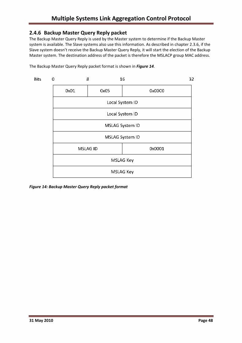
Multiple Systems Link Aggregation Control Protocol
2.4.6 Backup Master Query Reply packet The Backup Master Query Reply is used by the Master system to determine if the Backup Master system is available. The Slave systems also use this information. As described in chapter 2.3.6, if the Slave system doesn’t receive the Backup Master Query Reply, it will start the election of the Backup Master system. The destination address of the packet is therefore the MSLACP group MAC address. The Backup Master Query Reply packet format is shown in Figure 14.
Figure 14: Backup Master Query Reply packet format
31 May 2010 Page 48

Multiple Systems Link Aggregation Control Protocol
2.4.7 Query Acknowledgement packet The Query acknowledgement packets are used by the Master system and Backup Master system for additional certainty of the two‐way synchronisation packet flow. As only the Master system or Backup Master system send or receive these packets, the destination MAC address of the packet is the system MAC address. No additional information is needed for the acknowledgement, so the packet is also 24 bytes in length. The acknowledgement packet format is shown in Figure 15.
Figure 15: Query Acknowledgement packet format
31 May 2010 Page 49

Multiple Systems Link Aggregation Control Protocol
2.4.8 Master Claim packet The Master Claim packet is only sent during the Master Election process. Since the packet is intended to be received by all systems in the MSLACP synchronisation network, it is sent to the MSLACP group MAC address. As the Master system is not available when this packet is used, the MSLAG System ID is set to all zeros. The Master Claim packet format is shown in Figure 16.
Figure 16: Master Claim packet format
31 May 2010 Page 50

Multiple Systems Link Aggregation Control Protocol
2.4.9 Backup Master Claim packet The Backup Master Claim packet is sent during the Master Election process when a Master system is operational. As this packet is only intended to inform other systems of the claim, no additional information is needed and the packet is only 24 bytes in length. The destination address of the packet is the MSLACP group MAC address. The Backup Master Claim packet format is shown in Figure 17.
Figure 17: Backup Master Claim packet format
31 May 2010 Page 51

Multiple Systems Link Aggregation Control Protocol
2.4.10 Master Hello packet During Master operation, the system sends periodic Hello packets to all MSLAG systems. The Master Hello packets are only intended to inform the Backup Master and Slave systems on the availability of the Master, so no specific local configuration information needs to be synchronized in this packet. The packet length is therefore also 24 bytes and is sent to the MSLACP group MAC address . The packet format is shown in Figure 18.
Figure 18: Master Hello packet format
31 May 2010 Page 52
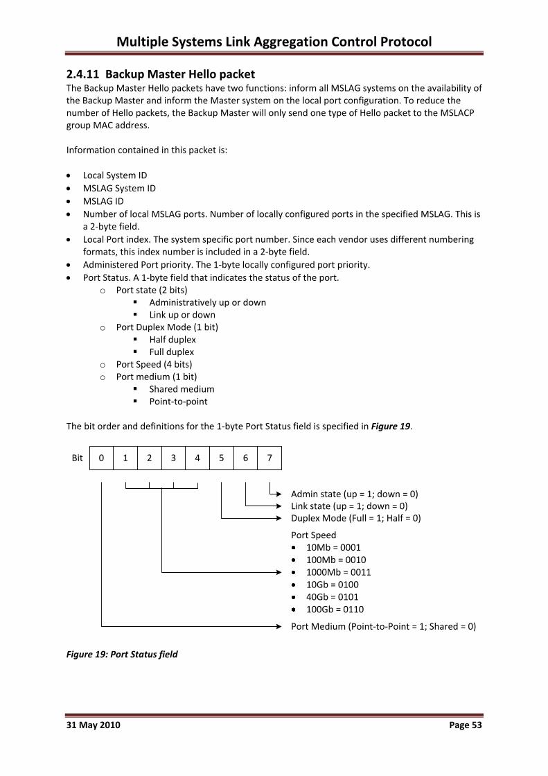
Multiple Systems Link Aggregation Control Protocol
2.4.11 Backup Master Hello packet The Backup Master Hello packets have two functions: inform all MSLAG systems on the availability of the Backup Master and inform the Master system on the local port configuration. To reduce the number of Hello packets, the Backup Master will only send one type of Hello packet to the MSLACP group MAC address. Information contained in this packet is: • Local System ID • MSLAG System ID • MSLAG ID • Number of local MSLAG ports. Number of locally configured ports in the specified MSLAG. This is
a 2‐byte field. • Local Port index. The system specific port number. Since each vendor uses different numbering
formats, this index number is included in a 2‐byte field. • Administered Port priority. The 1‐byte locally configured port priority. • Port Status. A 1‐byte field that indicates the status of the port.
o Port state (2 bits) Administratively up or down Link up or down
o Port Duplex Mode (1 bit) Half duplex Full duplex
o Port Speed (4 bits) o Port medium (1 bit)
Shared medium Point‐to‐point
The bit order and definitions for the 1‐byte Port Status field is specified in Figure 19.
Admin state (up = 1; down = 0)Link state (up = 1; down = 0)Duplex Mode (Full = 1; Half = 0)
Port Speed10Mb = 0001100Mb = 00101000Mb = 001110Gb = 010040Gb = 0101100Gb = 0110
Port Medium (Point‐to‐Point = 1; Shared = 0)
Bit 0 1 2 3 4 5 6 7
Figure 19: Port Status field
31 May 2010 Page 53

Multiple Systems Link Aggregation Control Protocol
The Backup Master Hello packet format is shown in Figure 20.
Figure 20: Backup Master Hello packet format The reserved bytes are for future extensions of the MSLACP protocol and are ignored in this version. These bytes are all zeros.
31 May 2010 Page 54

Multiple Systems Link Aggregation Control Protocol
2.4.12 Slave Hello packet The Slave Hello packet format is identical to the Backup Master Hello packet format, except for the destination MAC address and the packet type field. Since the Slave systems only inform the Master system on the local configuration and port status, the destination MAC address is the Master MAC address. The Packet Type field for this packet is 0x0B.
31 May 2010 Page 55

Multiple Systems Link Aggregation Control Protocol
2.4.13 MSLAG Configuration packet The Master system sends two types of configuration packets to the Backup Master system and Slave systems: Basic Configuration and LACPDU Configuration packets. The Basic Configuration packets are sent once for configuration of basic MSLAG information. Only when a change occurs, the Master system will send an update. The purpose of this information is to configure the local MSLAC. All information needed for local decisions is sent in this packet. The LACPDU Configuration packets are sent on a regular basis. The information in the IEEE802.1AX™ standard (IEEE, 2008b) LACPDU packets that is likely to dynamically change during operation based on the Partner system LACPDU packets, is send to the remote systems by the Master system. The MSLAG Configuration packet contains a type field that indicates the type of configuration packet. The MSLAG Configuration packets are sent to each remote system’s MAC address. Basic Configuration packet The basic configuration packet contains information on the system’s port configuration. All local MSLAG port configurations are sent in a single configuration packet. The information that is sent in the basic configuration packet is: • Local System ID • MSLAG System ID • MSLAG ID • Configuration type. A 1‐byte field from which the Most Significant Bit (MSB) of the field indicates
whether the packet is a Basic (0) or LACPDU (1) configuration packet. The seven remaining bits are reserved for future use.
• Number of MSLAG ports. Number of ports this packet contains configuration for. This is a 2‐byte field.
• Port configuration o Port index. The system specific port number. This is the index number the Master
system learned from the Hello packets and is included in a 2‐byte field. o Port ID. The Master system assigns each port in the MSLAG a unique Port Identifier. The
assignment of MSLAG Port ID’s is described on page 27. The Port ID field is a 2‐byte field. o MSLAG Port Operational Key. As described in the IEEE802.1AX™ standard (IEEE, 2008b),
this key is the operational key that is used by the systems to form aggregations. Only ports with the same operational key can be aggregated. This field is 2 bytes long.
o MSLAG Port Administrative Key. This key allows manipulation of Key values by management. This field is 2 bytes long.
o Forced Port State byte. 1 byte field with the forced Port State. Port Standby State bit. This field is used by the Master system to limit the
number of active links in the aggregation group. When the Master system needs to limit the number of ports in an aggregation group (due to physical limitations or an administratively set limitation), it sets the standby state of low priority ports to 1, until the number of active ports is equal to the limitation. When this bit is 0, the port is eligible for aggregation.
Port error state bit. When this bit is set, it indicates that an error has occurred. A port with this bit set cannot be aggregated. The type of error is mentioned in the next six bits (three reserved for future use) and is only used by the remote system for troubleshooting purposes.
Speed error bit. When the port operates at a different speed than the higher priority ports, this bit is set.
31 May 2010 Page 56

Multiple Systems Link Aggregation Control Protocol
Duplex mode bit. When the port is in Half Duplex, this bit is set. Shared Medium bit. When the port is set, the port is of a Shared Medium and
cannot be aggregated. The bit order of the Forced Port State byte is shown in Figure 21.
Figure 21: Forced Port State byte The basic configuration packet format is shown in Figure 22.
31 May 2010 Page 57

Multiple Systems Link Aggregation Control Protocol
320 168
0x01 0x0C Packet Length
Local System ID
Local System ID
MSLAG System ID
MSLAG System ID
MSLAG ID
Bits
0x0001
MSLAG Key
MSLAG Key
Local Port 1 index
Operational Key
# local MSLAG Ports (1‐n)Cfg Type (0x00) reserved
Port Identifier
Administrative Key
Port State reserved
Local Port n index
Operational Key
Port Identifier
Administrative Key
reservedPort State
Figure 22: Basic Configuration packet format The remote systems store the information per port in a local database and use it for local MSLACP decisions. Only when the system receives an updated configuration from the Master system or when a Master Change has occurred, the port configuration is changed.
31 May 2010 Page 58

Multiple Systems Link Aggregation Control Protocol
LACPDU Configuration packet The LACPDU configuration packets contain the extra information the local system needs to be able to send the LACPDUs to IEEE802.1AX™ Partner systems. As described in chapter 5.4.2.2 of the IEEE802.1AX™ standard (IEEE, 2008b), the MSLACP system sends out LACPDU packets on all MSLAG ports to communicate with the IEEE802.1AX™ Partner system. The Actor information in these LACPDU packets is defined by the Master system and is sent to each individual MSLAG system. The Partner information that is part of the LACPDU packets is locally received by the MSLAG systems on each port and is sent to the Master system. The Master system uses this Partner information to decide on the appropriate port action. As this information does not change, the local systems use this locally stored information in the LACPDU packets and is therefore not part of the MSLAG configuration packets. The Actor information in the LACPDU packets as defined in the IEEE802.1AX™ standard (IEEE, 2008b) contain: • Actor_System_Priority. This is the MSLAG System Priority and is included in the LACPDU
Configuration packet. (2 bytes) • The Actor_System_ID is the MSLAG System ID and is included in the protocol header. (8 bytes) • Actor_Key. This operational key is part of the MSLAG Basic Configuration packet. (2 bytes) • Actor_Port_Priority. The Master system rewrites the locally administered Port Priorities when
needed. This only occurs when there are identical Port ID’s as mentioned on page 27. The Port Priority is sent in the LACPDU configuration packet, even if the local administered priority is used. (2 bytes)
• Actor_Port. The Master system defines the port numbers across the MSLAG. Each MSLAG port has a unique number and is sent to the systems in the LACPDU configuration packets. (2 bytes)
• The Actor_State variables are defined by the Master system and are sent in the LACPDU configuration packet. (1 byte)
• The Partner_State variables. As this state is the Actor’s view on the Partner’s state, this variable is also part of the LACPDU configuration packet. (1 byte)
The CollectorMaxDelay value (2 bytes) is also defined by the Master system and is sent in the LACPDU configuration packet. The LACPDU Configuration packet format is shown in Figure 23.
31 May 2010 Page 59
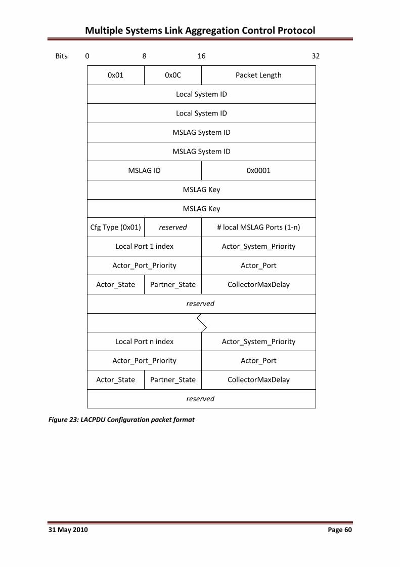
Multiple Systems Link Aggregation Control Protocol
320 168
0x01 0x0C Packet Length
Local System ID
Local System ID
MSLAG System ID
MSLAG System ID
MSLAG ID
Bits
0x0001
MSLAG Key
MSLAG Key
Local Port 1 index
# local MSLAG Ports (1‐n)Cfg Type (0x01) reserved
Actor_System_Priority
Local Port n index
reserved
Actor_Port_Priority Actor_Port
Actor_State Partner_State CollectorMaxDelay
reserved
Actor_System_Priority
Actor_Port_Priority Actor_Port
Actor_State Partner_State CollectorMaxDelay
Figure 23: LACPDU Configuration packet format
31 May 2010 Page 60
Multiple Systems Link Aggregation Control Protocol
2.4.14 MSLAG Partner Information packet Since the state of a MSLAG port is determined by the Master system’s MSLAC, the Master system needs all relevant information of the Partner system connected to the MSLAG. This information is send by the Partner system in LACPDU packets when ports of the MSLAG try to form an adjacency. This Partner information must then be sent to the Master system by all remote systems. This is done in MSLAG Partner Information packets. When a remote system (Backup Master or Slave) receives an LACPDU packet (since this is sent to the Slow_Protocols_Multicast address as defined in the IEEE802.3™ standard (IEEE, 2008a), the packet rate is 10 frames per one second), it forwards the relevant received Actor information (thus the Partner system port information) that is contained in the LACPDU packet, to the Master system. The packet rate of the MSLAG Partner information packet is also at a rate of 10 frames per second. Each packet contains information of all MSLAG ports on the remote system. The information per port is the last received LACPDU packet. The Partner system port information (as defined in the IEEE802.1AX™ standard (IEEE, 2008b)) that is sent to the Master system is: • System_Priority. The priority assigned to the Partner system (by management or administration
policy), encoded as an unsigned integer. (2 bytes) • System_ID. The Partner’s System ID, encoded as a MAC address. (6 bytes) • Key. The operational Key value assigned to the port associated with this link by the Partner
system, encoded as an unsigned integer. (2 bytes) • Port_Priority. The priority assigned to this port by the Partner system (by management or
administration policy), encoded as an unsigned integer. (2 bytes) • Partner_Port. The port number associated with this link assigned to the port by the Partner
system, encoded as an unsigned integer. (2 bytes) • Partner_State. The Partner’s state variables for the port, encoded as individual bits within a
single byte. (1 byte) Since the MSLAG Partner Information packet is only relevant to the Master System, these packets are sent to the Master’s MAC address. The MSLAG Partner Information packet format is shown in Figure 24.
31 May 2010 Page 61

Multiple Systems Link Aggregation Control Protocol
320 168
0x01 0x0D Packet Length
Local System ID
Local System ID
MSLAG System ID
MSLAG System ID
MSLAG ID
Bits
0x0001
MSLAG Key
MSLAG Key
Local Port 1 index
# local MSLAG Ports (1‐n)reserved
Partner_System_Priority
Local Port n index
reserved
Partner_System_ID Partner_Port_Key
Partner_Port
Partner_System_ID
Partner_Port_Priority
Partner_State
Partner_System_Priority
reserved
Partner_System_ID Partner_Port_Key
Partner_Port
Partner_System_ID
Partner_Port_Priority
Partner_State
Figure 24: MSLAG Partner Information packet format
31 May 2010 Page 62

Multiple Systems Link Aggregation Control Protocol
2.4.15 MSLAG FDB Synchronisation packet Each system sends forwarding database updates to all systems in the MSLAG on the MSLACP synchronisation link using the MSLAG Multicast MAC address. There are two types of FDB updates: • Learned entry: A new MAC address is learned on a specific port. This port can be either an
individual port that is not part of the MSLAG, or an MSLAG port. • Released entry: An entry in the local FDB has timed out and is removed from the FDB. The information that is send in the synchronisation packets is: • Number of entry updates in the packet • Per entry the following information is included:
• Layer 2 VLAN id in which the entry is learned. This VLAN id is a 12 bits field. • Type field to indicate the update. This type field is a 4‐bits field.
o 0x1 indicates an entry learned on an individual port or a different (MS)LAG port. o 0x2 indicates an entry learned on an MSLAG port. o 0x3 indicates an entry that has been released due to a time‐out or a disconnected
physical port. • Learned or released MAC address. This is the 6‐byte MAC address.
Since the remote systems in the MSLAG do not use the remote port information to update their database, no port information is included. When an entry is learned on a remote individual port, or on another (MS)LAG on the remote system, the entry is stored in the local FDB with the MSLAG synchronisation port as destination port. This is only relevant if the Layer 2 VLAN id. is locally available and if the Layer 2 VLAN is properly configured on the MSLAG synchronisation port. When an entry is learned on a remote MSLAG port, the local FDB will be updated with the entry with the local MSLAG as corresponding destination port. A released entry is removed from the FDB when the destination port as stored in the FDB is the MSLAG synchronisation port. When the destination port of the stored entry is the local MSLAG, the update will be ignored. This because a disconnected port on the remote system might be the reason of the disconnection. The MSLAG FDB Synchronisation packet format is shown in Figure 25.
31 May 2010 Page 63

Multiple Systems Link Aggregation Control Protocol
Figure 25: MSLAG FDB Synchronisation packet format
31 May 2010 Page 64

Multiple Systems Link Aggregation Control Protocol
2.4.16 Master Synchronisation packet The Master system synchronises the Backup Master system with all information that is needed for a non‐disruptive Master Change. These packets are sent to the Backup Master system’s MAC address. The Backup Master system only needs information on any Slave systems that are active since the Master Change occurs when the Master system is not available. If no Slave systems are active (the MSLAG only consists of two systems), no Master Synchronisation packets are sent. Since the Backup Master system is part of the MSLAG, it has all global MSLAG information already locally stored. Information the Backup Master requires about the Slave systems is: • Number of Slave systems • Specific information per Slave system
o Slave System ID (8 bytes) o Number of local MSLAG ports (2 bytes) o Per port configuration
Local port configuration • Local Port Index (2 bytes) • Port Administrative key (4 bytes) • Port Status as defined in Figure 19 (1 byte)
o State (2 bits) o Duplex Mode (1 bit) o Speed (4 bits) o Medium (1 bit)
Port configuration by Master system • MSLAG Port ID (2 bytes) • Forced Port State as defined in Figure 21 (1 byte)
o Port Standby State bit o Port Error State bit o Speed Error bit o Duplex Mode bit o Shared Medium bit
• Port Priority (2 bytes) • Actor_State variable (1 byte) • Partner_State variable (1 byte)
Port Partner Information as described in chapter 2.4.14. • System_Priority (2 bytes) • System_ID (6 bytes) • Key (2 bytes) • Port_Priority (2 bytes) • Partner_Port (2 bytes) • Partner_State (1 byte)
The Master Synchronisation packet format is shown in Figure 26.
31 May 2010 Page 65

Multiple Systems Link Aggregation Control Protocol
Figure 26: Master Synchronisation packet format
31 May 2010 Page 66

Multiple Systems Link Aggregation Control Protocol
2.4.17 Master Change packet When the Master system is not available, the Backup Master system first sends a Master Query to the MSLACP group MAC address. If no Master Query Reply packets is received, the Backup Master system will send the Master Change packet to each Slave system using the Slave system’s MAC address. The Master Change packet is only intended to inform the Slave systems on the failover and contains the following information: • MSLAG ID • MSLAG Key • MSLAG System ID • Backup Master System ID The Slave systems compare the information in the Master Change packet with the locally stored Backup Master System ID and MSLAG System ID. Only if the different ID’s are identical, the Slave system will process the Master Change. The Master Change packet format is shown in Figure 27.
Figure 27: Master Change packet format
31 May 2010 Page 67

Multiple Systems Link Aggregation Control Protocol
2.4.18 Master Change Acknowledgement packet The Slave systems send a Master Change Acknowledgement packet to the Backup Master system when the Master Change is received and approved. As the MSLAG System ID doesn’t change during a Master Change, the information in the acknowledgement packet is restricted to the information in the protocol header. The Master Change Acknowledgement packet format is shown in Figure 28.
Figure 28: Master Change Acknowledgement packet format
31 May 2010 Page 68

Multiple Systems Link Aggregation Control Protocol
2.5 MSLACP constraints
Investigating the MSLACP protocol and the behaviour as depicted in the flowcharts in chapter 2.3, there are some circumstances that can have an impact on the behaviour of MSLACP. This applies not only to a standard operational MSLACP system, but rather when a fault happens. As MSLACP is dependent on external factors, not all failures can be prevented in the protocol design. In the next paragraphs the most important external faults are described. The MSLACP functionality depends on the availability of the synchronisation connection. When no synchronisation is possible, this might result in unpredictable behaviour and potential loss of operational data traffic. Loss of the synchronisation connection occurs when the local link is down, or the synchronisation network is unavailable due to a malfunction of any kind. The possibility of losing the synchronisation must be minimized. When the synchronisation connection is lost and two or more MSLACP systems are isolated from each other, all systems will start the Master Function as described in the flowchart of the Backup Master Function in chapter 2.3.4. Since MSLACP provides in a non‐disruptive Master failover, which means that the former Backup Master system will maintain the original System ID and operational key, two or more Master systems are active, from which two (the original Master and former Backup Master) will actually form Partner connections with the Partner system. The former Slave systems that become Master system when isolated will use different System ID’s and operational keys and these links will not be aggregated by the IEEE802.1AX™ Partner system. When the synchronisation connection returns, one of the Master systems will have to return to the Backup Master or Slave Function. This behaviour is not provided in the MSLACP design workflows as described in chapter 2.3 and will have to be part of further research. In an incorrectly configured MSLACP environment, duplicate MSLAG messages on different synchronisation VLANs can occur. This might impact the behaviour of local systems and must be avoided. To avoid all of these circumstances or to minimize the chance of these circumstances to happen, design guidelines are formulated. The design guidelines are described in chapter 3. Whether the design guidelines are sufficient to avoid the mentioned circumstances is described in the evaluation in chapter 4.
31 May 2010 Page 69

Multiple Systems Link Aggregation Control Protocol
3 MSLACP Design Guidelines
As described in the basic assumptions (chapter 2.2.4), there are recommended design guidelines for implementing MSLACP in the network. When these guidelines are followed, a single fault in the network will provide predictable behaviour of the MSLACP functionality.
3.1 IEEE802. 1AX™ guidelines Since the MSLACP protocol is intended to be compatible with the IEEE802.1AX™ standard for link aggregation (IEEE, 2008b), the guidelines as described in the standard are applicable. This applies to local configuration of ports. The first version of the MSLACP protocol as described in this dissertation is not compatible to the full features as described in the LACP standard. The optional feature Marker Generator/Receiver is not supported. The ability to respond to Marker PDU’s is done locally by the MSLACP system’s LAC. The support for the (optional) features as described in the IEEE standard depend on the LACP feature support by the individual systems. For instance, the frame distribution algorithm is a local function and can vary across the MSLAG systems.
3.2 Physical guidelines To implement MSLACP using multiple systems, the following physical guidelines are recommended: • All ports in an MSLAG are of the same speed and duplex mode. Support of different mediums is
optional to the vendor’s implementation. • As the synchronisation of the different MSLACP systems is crucial, the MSLACP synchronisation
link is recommended to be redundant. The use of an IEEE802.1AX™ aggregated trunk for the synchronisation link is preferred.
• The IEEE802.1AX™ trunk can be a point‐to‐point synchronisation link when only two systems are part of the MSLAG. When more than two systems are used to distribute the MSLAG, a redundant connection to a layer 2 switched network must be provided. This switched network must also be redundant to prevent a single fault to disrupt the system.
• In normal operation the synchronisation link is used for synchronisation traffic only and doesn’t need much bandwidth. But when an asymmetric design is used (not all partner systems are connected to all MSLAG systems), or a problem in one of the links has occurred, traffic might traverse the synchronisation link. The synchronisation link should therefore be calculated to have enough bandwidth for regular data throughput. This means that the bandwidth of the synchronisation link (or trunk) should be at least the connected bandwidth of the Partner system with the largest connection bandwidth.
An example of an MSLACP design is shown in Figure 29.
31 May 2010 Page 70

Multiple Systems Link Aggregation Control Protocol
Figure 29: MSLACP design example In this design multiple MSLAG ID’s are configured across four MSLACP capable systems. For each MSLAG ID the same synchronisation VLAN ID on the synchronisation network is used. The data VLANs that are configured on the MSLAG trunks to the partner systems are also configured in the synchronisation network. Since MSLAG ID’s 1 and 3 only use two of the four systems, the data VLANs used on these ID’s are only required on the MSLACP systems with that same ID. Configuring all data VLANs on all MSLACP systems is optional. It is possible to use multiple synchronisation connections for the different MSLAG ID’s. For instance in the example design in Figure 29 the two switches to which MSLAG ID 3 is connected can have a direct (redundant) synchronisation connection (as indicated by the dotted lines) beside the synchronisation network for MSLAG ID 2. When multiple synchronisation connections or networks are used, there is a risk of looped data VLANs when these are configured on both synchronisation networks. To prevent this, always use only one of the synchronisation networks for interconnecting the data VLANs between the MSLACP switches. The design of the synchronisation network is independent to the MSLACP design, as long as synchronisation is secured. It can be a star or ring topology or even make use of a Provider network. The only requirement is that it is a layer 2 domain, Quality of Service is provided for the MSLACP protocol and multiple VLANs are supported.
3.3 Configuration guidelines Besides the physical guidelines, also some configuration guidelines must be taken into account. • The synchronisation of MSLAG systems is done using a layer 2 VLAN. Because of the importance
of the synchronisation traffic, the traffic sent in this synchronisation VLAN must be treated with a higher priority than standard data traffic.
• To prevent a loop to happen in the network due to a human configuration error or a faulted system, it is advised to configure a loop prevention mechanism on all MSLACP ports, including the synchronisation ports.
• When implementing the MSLACP protocol, the implementation must prevent the possibility of multiple individual synchronisation links. Only one synchronisation link or network is permitted per MSLAG ID. Multiple MSLAG ID’s can use the same synchronisation link or network.
31 May 2010 Page 71

Multiple Systems Link Aggregation Control Protocol
4 Evaluation and Results The MSLACP protocol has not been evaluated using actual systems because there are obviously no actual implementations. The evaluation therefore is done by defining possible scenarios and theoretically determining the impact on the system when the guidelines as described in chapter 3 are used. The following major fault or change scenarios are defined: • Broken synchronisation link. • Loss of synchronisation network. • Recovery of synchronisation network, resulting in two Master Systems for the same MSLAG. • Broken IEEE802.1AX™ Partner link. • Adding ports or a system to an operational MSLAG. • Loss of a Master system. • Return of the former Master system. • Loss of a Backup Master system. • Return of the former Backup Master system. • Loss of a Slave system. • Duplicate MSLAG messages on different synchronisation VLANs due to a local configuration
error. Broken synchronisation link Since according to the design guidelines the synchronisation link is a redundant connection, loss of a single synchronisation link has no impact on the MSLACP system because the redundant connection will stay operational. Loss of synchronisation network When both synchronisation links are down or when only one synchronisation link is used due to physical restrictions, there is no connection between the different MSLACP systems. The original Master system will continue forwarding traffic to and from the locally connected IEEE802.1AX™ Partner system. The Backup Master system will issue a Master Change and will also become Master system. Since the operational key and MSLAG ID don’t change during a Master Change to provide for a non‐disruptive failover, the connections with the IEEE802.1AX™ Partner systems will continue to be operational. When there is a symmetrical design, traffic will be forwarded as before. The forwarding database of the different systems though will not be synchronised so all systems will have to learn the forwarding information individually. When the network design is asymmetrical, traffic destined for a single attached station or network will be lost, depending on the distribution of the traffic in the IEEE802.1AX™ Partner system. This will result in an unpredictable network behaviour and loss of functionality for clients. In this design, compliance with the design guidelines for the synchronisation link or network is crucial to reduce the chance of this unpredictable behaviour. Recovery of synchronisation network, resulting in two Master Systems for the same MSLAG When two Master systems are active and connected to an IEEE802.1AX™ Partner system (due to a loss of the synchronisation network) and the synchronisation network recovers, two Master systems for the same MSLAG are active. If this happens, the system that used to be the Backup Master system and became Master system in the Master Change process should become Backup Master system again or, when one or multiple Backup Master systems are active after the Master Change,
31 May 2010 Page 72

Multiple Systems Link Aggregation Control Protocol
Slave system without interrupting data traffic. In the Master process as described in chapter 2.3.3, this change from Master system to Backup Master system or Slave system is not described. When a redundant synchronisation network is used, this fault is unlikely to happen, but is not impossible. Introducing a solution for this is part of the future work for this protocol. Broken IEEE802.1AX™ Partner link When an IEEE802.1AX™ Partner link disconnects, or when the local MSLAC of a system detects a configuration change on the IEEE802.1AX™ Partner system, the MSLAC sends an update to the Master system. The Master system will then, according to the MSLACP rules, reconfigure the remote systems. If an MSLAG port is in Standby Mode, the Master system sends a configuration change to that specific remote system to change the port state to active. If multiple ports are in Standby Mode, the Master system will activate the port with the highest priority. Adding ports or a system to an operational MSLAG When ports or a new MSLACP system is added to an operational MSLAG, the Master system of the MSLAG reconfigures the added ports according to the MSLACP standard. The ports with the highest priority are treated accordingly, what might result in reconfiguration of active ports to Standby Mode. According to the IEEE802.1AX™ standard, “Parallel links could be automatically configured as standby links, and deployed to mask link failures without any disruption to higher layer protocols.” (IEEE, 2008b, p.63). This same behaviour applies when a broken link that used to be an active link returns. Loss of a Master system When the Master system is unavailable, the Backup Master system starts the Master Change process. During this process, data throughput will continue since the MSLAG ID and operational port keys don’t change. Clients on the network will not lose connectivity, unless these clients are singular connected to the lost system (asynchronous network design). Return of the former Master system When the former Master system returns from a failure, it starts the MSLACP process. In this process the first action is to check if a Master system for the MSLAG is available by sending Master Query packets. The system that has taken over the Master Function of the MSLAG replies to the queries. The former Master system then starts as Backup Master system or Slave system, even if the local System ID of the system is identical to the MSLAG ID. Loss of a Backup Master system When the Backup Master system becomes unavailable, the existing (if any) Slave systems start electing a new Backup Master system. This process is described in chapter 2.3.2. After the reelection of a Backup Master system, the Master system starts synchronizing the new Backup Master system. In an asynchronous network design, locally attached networking equipment lose connectivity to the rest of the network. In a synchronous network design, there is no loss of connectivity other than a reduction of available bandwidth. Return of the former Backup Master system When the former Backup Master system returns, it starts the MSLACP process. During this process it detects the availability of the Master system and Backup Master system (if multiple systems are part of the MSLAG). If no Backup Master system is available, the returning system starts the Backup Master Function again. When a Backup Master system is available, the former Backup Master system will start the Slave Function process.
31 May 2010 Page 73

Multiple Systems Link Aggregation Control Protocol
Loss of a Slave system When the Slave system is lost, the Master system reconfigures the MSLAG ports and activates available standby ports. In an asynchronous network design, locally attached networking equipment lose connectivity. In a synchronous network design, there is no loss of connectivity other than a reduction of available bandwidth. Duplicate MSLAG messages on different synchronisation VLANs due to a local configuration error As described in the configuration design guidelines (chapter 3.3), the implementation of MSLACP on a system prevents a system to send MSLAG synchronisation packets on multiple links or networks. But when a configuration error occurs on the external synchronisation network, duplicate MSLAG messages might be received on different synchronisation VLANs. The MSLACP systems only process MSLAG synchronisation data if received on the correct (locally configured) synchronisation ports. This prevents for any synchronisation errors due to duplicated packets.
31 May 2010 Page 74
Multiple Systems Link Aggregation Control Protocol
5 Conclusion and Future Work
The purpose of MSLACP is to offer a standards based link aggregation mechanism across multiple systems. By using a synchronisation network, a new synchronisation protocol and standard IEEE802.1AX™ parameters, MSLACP meets the demands for a relatively simple extension of the IEEE802.1AX™ standard. Benefits of MSLACP in respect to the IEEE802.1AX™ standard or proprietary mechanisms are: • With MSLACP networking vendors can be flexible in providing link aggregation using a
combination of IEEE802.1AX™ for aggregation of local links, vendor proprietary aggregation of local and remote links and aggregation of local and remote links using MSLACP.
• MSLACP has the benefit of aggregating links on systems produced by different vendors. • Almost all proprietary mechanisms are restricted to a pair of switches with a direct connection
for synchronisation. Using MSLACP, more than two systems can be used. Using this, not only a dual core design, but also triangular or square designs are possible.
• Vendors with no research and development budget for developing a proprietary mechanism have the opportunity to easily implement the standards based mechanism.
• Due to the lightweight protocol, implementing MSLACP on relatively simple workgroup switches is possible.
• The possibility of aggregating links across platforms from different vendors is useful for migration purposes or for companies that don’t want to be locked in by a single vendor.
• Using MSLACP in server blade systems, multiple blade systems can be connected to the network using a single aggregated connection. Microsoft Network Load balancing (Microsoft, 2008) for instance use multiple physical servers that are accessed by clients using a single MAC address. By using MSLACP these different servers can be connected to local switches. Synchronisation of Network Load Balancing servers using a different network interface need further investigation.
Whether or not the MSLACP protocol will be implemented by networking equipment vendors depend on several conditions: • Does the vendor have a proprietary functionality for aggregating links on different systems?
When a vendor has implemented its own protocol or mechanism, implementing the MSLACP protocol has no priority.
• Do server cluster applications offer the possibility for a client to randomly connect to another physical server?
• What is the business case for the vendors? If vendors are able to define the economical benefit of MSLACP, adoption of MSLACP is more likely. These economic benefits may vary per vendor.
31 May 2010 Page 75

Multiple Systems Link Aggregation Control Protocol
The research of MSLACP has been limited due to the time limitation of the dissertation project. Some parts of the protocol needs further enhancement, and implementation of additional functionality in MSLACP is recommended to fully comply to also the optional parts of the IEEE802.1AX™ standard. The next steps for development of the MSLACP protocol are: 1. Improve the Master system process to define the system behaviour when two Master systems
are present for the same MSLAG. This scenario might occur when the synchronisation network is temporarily unavailable.
2. Investigate the duration of the wait state timers and define the minimum and maximum values. 3. Investigate whether direct synchronisation of the Backup Master system by the Slave systems is
preferred instead of only Master synchronisation. 4. Data encryption of communication packets on the synchronisation network. 5. Implementation of the IEEE802.1AX™ Marker Protocol. 6. Extend the LACP Systems Management as described in the IEEE802.1AX™ standard to support
MSLACP. 7. Investigate the termination of a single L2‐VPN endpoint (ME or MPLS) to an MSLAG spanning
multiple systems. This might impact the mechanism of synchronisation of end‐points or introduces a virtual end‐point.
31 May 2010 Page 76

Multiple Systems Link Aggregation Control Protocol
6 References Alcatel‐Lucent (2008) Multi‐Chassis Link Aggregation Group Redundancy for Layer 2 Virtual Private Networks; Enhancing Network Capacity and Redundancy using Multi‐Chassis Link Aggregation Groups. [Internet], Technology Information Guide. Alcatel‐Lucent. Available from: http://www.alcatel‐lucent.com/wps/portal/Products/ [Accessed 22 December 2009]. Bocci, M., Cowburn, I. and Guillet, J. (2008) Network High Availability for Ethernet Services Using IP/MPLS Networks. IEEE Communications Magazine, March 2008, pp. 90‐96. Cisco Systems, Inc. (2006) Cisco Catalyst 6500 Series Virtual Switching System (VSS) 144. [Internet], White Paper. Cisco Systems, Inc.. Available from: <http://www.cisco.com/en/US/products/hw/ switches/ps708/prod_white_papers_list.html> [Accessed 22 December 2009]. Cisco Systems, Inc. (2009) Virtual PortChannels: Building Networks without Spanning Tree Protocol. [Internet], White Paper. Cisco Systems, Inc.. Available from: <Error! Hyperlink reference not valid.> [Accessed 22 December 2009]. Institute of Electrical & Electronics Engineers, Inc. (2004) IEEE Std 802.1D™‐2004 – Media Access Control (MAC) Bridges. New York, IEEE. Institute of Electrical & Electronics Engineers, Inc. (2005) IEEE Std 802.1AB™‐2005 – Station and Media Access Control Connectivity Discovery. New York, IEEE. Institute of Electrical & Electronics Engineers, Inc. (2008) IEEE Std 802.3™‐2008 ‐ Telecommunications and information exchange between systems ‐ Local and metropolitan area networks ‐ Specific requirements ‐ Part 3: Carrier Sense Multiple Access with Collision Detection (CSMA/CD) Access Method and Physical Layer Specifications. New York, IEEE. Institute of Electrical & Electronics Engineers, Inc. (2008) IEEE Std 802.1AX™‐2008 – Link Aggregation. New York, IEEE. Institute of Electrical & Electronics Engineers, Inc. (n.d.) Group MAC address assignments for standards use, [Internet], New York, IEEE. Available from: <http://standards.ieee.org/regauth/groupmac/Standard_Group_MAC_Address_assignments.pdf> [Accessed 23 April 2010]. International Organisation of Standardisation and International Electrotechnical Commission. (2002) ISO/IEC 10589:2002(E) Information technology ‐ Telecommunications and information exchange between systems – Intermediate System to Intermediate System intra‐domain routeing information exchange protocol for use in conjunction with the protocol for providing the connectionless‐mode network service (ISO 8473). Geneva, ISO/IEC. Internet Engineering Task Force (1998) Request for Comments: 2328 ‐ OSPF Version 2. Fremont CA, IETF. Juniper Networks, Inc. (2009) Virtual Chassis Technology Best Practices. [Internet], Implementation Guide. Juniper Networks, Inc.. Available from: <http://www.juniper.net/us/en/products‐services/switching/ex‐series/ex4200/#literature> [Accessed 19 January 2010].
31 May 2010 Page 77

Multiple Systems Link Aggregation Control Protocol
31 May 2010 Page 78
Microsoft (2008) Network Load Balancing Deployment Guide. [Internet], Redmond WA, Microsoft. Available from: <http://technet.microsoft.com/nl‐nl/library/cc732855(WS.10).aspx> [Accessed 20 May 2010] Nortel Networks (2005) Resilient Terabit Clustering. [Internet], White Paper. Nortel Networks. Available from: <http://www.nortel.com/promotions/whitepaper/rtca/collateral/nn111500‐041405.pdf> [Accessed 19 Januari 2010]. Nortel Networks (2009) Nortel Ethernet Routing Switch 8600 Planning and Engineering ‐ Network Design, release 5.1, revision 02.01. [Internet], Nortel Networks. Available from: <Error! Hyperlink reference not valid.> [Accessed 22 December 2009]. Rungta, S. & Ben‐Shalom, O. (2006) Enterprise Converged Network – One Network for Voice, Video, Data and Wireless. Intel Technology Journal [Internet], 15 February, 10 (01), pp. 1‐12. Available from: <http://developer.intel.com/technology/itj/index.htm> [Accessed 9 June 2009]. Van ‘t Spijker, R. (2009) Are Network Service Provider techniques fit to meet Enterprise networks service demands? APP Module report. Leeds Metropolitan University.