riley stoker corp. is now riley power inc., a babcock power … · 2018-02-01 · coy burner...
TRANSCRIPT
STATUS OF NOx CONTROL TECHNOLOGYAT RILEY STOKER
by
R.A. LisauskasE.L Reicker
T. DavisRiley Stoker Corporation
Worcester, Massachusetts
ABSTRACT An overview of on-going efforts at Riley Stoker to develop improved low-NOxcombustion technologies for both new and existing boilers is presented. A new ControlledCombustion Venturi (CCV) burner design is described along with full-scale burner testdata from the Riley Research coal burner test design. In addition, recent overfire air systemoperating experience is discussed. Field test data from a 400 MW coal-fired utility boilerretrofitted with new overfire air NOx controls are presented.
The application of NO, controls to incineration and fluidized bed combustion are alsoreviewed. Pilot-scale test results from a municipal solid waste (MS W) combustor are com-pared with full-scale field data. Experiments have also been conducted addressing the ef-fectiveness of gas reburning applied to mass burn incineration systems. The paper con-cludes with a brief summary on the status of NOx controls for circulation fluidized bedboilers.
The average age of the U.S. utility and industrialboiler population continues to rise, while acid rainlegislation becomes increasingly likely. Several stateshave, or will enact NOx control legislation of theirown. NOx control, therefore, may soon be requiredon boilers not currently regulated under FederalNew Source Performance Standards (NSPS). NOxcontrol research, therefore, has remained animportant element in Riley Stoker's pro-ductdevelopment and overall business strategies.
This paper provides an overview of recent effortsat Riley Stoker to develop low-NOx combustioncontrol technologies for both existing and new utili-ty and industrial boiler systems. Overfire air and lowNOx burners continue to represent two of the mostcost effective retrofit low-NO, combustion controltechnologies for pre-NSPS boilers. In our updategiven at the 1987 Joint Symposium we discussedplans to upgrade our low-NOx coal burnertechnology, the Controlled Combustion Venturi (CCV) burner, and to improve overfire air systemperformance on an existing utility coal-fired
boiler. The results of these activities are presentedhere.
We will also discuss the development of NOxcontrols for several new boiler technologies. Pilot-scale studies are underway to investigate the effec-tiveness of natural gas reburning in reducing NO,emissions from municipal solid waste combustion.A new combustion test facility has been constructedto support this research. Circulating fluidized bedboilers have become the combustion technology ofchoice in many new industrial coal-fired boiler ap-plications. Low combustion temperatures combin-ed with staged combustion offer the potential forachieving significant lower NOx emission levelsthan conventional coal-fired systems. Riley Stoker iscurrently under contract with the U.S. Departmentof Energy to develop an advanced coal-firedfluidized bed combustion system capable of con-trolling NOx emissions to 0.1 lb/106 Btu or less.
® Riley Stoker Corporat ion 1988
COY BURNER DEVELOPMENT
The Riley Controlled Combustion Venturi (CCV)burner (U.S. Patent No. 4,479,442) was originallydeveloped as a low-NOX coal burner for wall-firedboiler retrofit applications. Our initial retrofit ex-perience on three utility boilers was first discussedat the 1982 Joint Symposium(». In order to extendthe performance of this low-NO, burnertechnology over a wider range of operating condi-tions additional design improvements have beendeveloped and implemented. The performance ob-jectives for this second generation CCV burnerdesign were as follows:• Improved mechanical reliability and operability
of the secondary air register system.• Reduced air side pressure drop requirements for
wider retrofit application.• Improved low-load operation.• Maintain low-NOx characteristics.
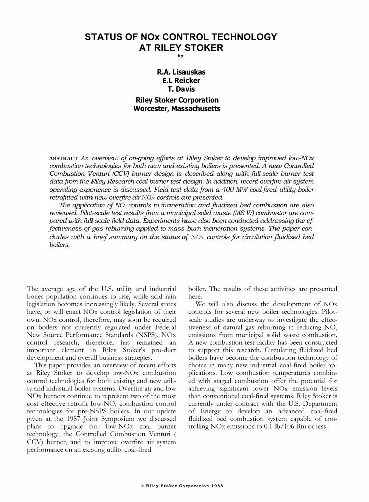
The second-generation CCV burner design is il-lustrated in Figure 1. NOx control is still achievedthrough a patented venturi coal nozzle and low swirlcoal spreader design. Control of fuel and air mix-ing is achieved by separating the primary air/coal
stream into fuel-rich and fuel-lean layers beforemixing into the secondary air. In addition to theventuri nozzle, the second-generation CCV burnerincorporates a new secondary air register design forswirl and air flow control. Curved, overlapping airregister turning vanes provide improved swirl con-trol at lower pressure drop. Secondary air flow iscontrolled by a movable shroud that slides over thesecondary air register entrance. Independent con-trol over both the shroud and air turning vane posi-tions offers significant flexibility in controlling com-bustion even at low load. Inlet secondary air veloci-ty is controlled at low loads by partially closing theshroud. As a result, swirl and flame stabilization aremaintained even under low load staged combustionoperation. The entire air register mechanism hasbeen redesigned and moved to the burner plateaway from the hot firing wall for improvedmechanical reliability.
Figure 1. Second Generation CCV Burner with New Secondary Air Register and Movable Shroud
2
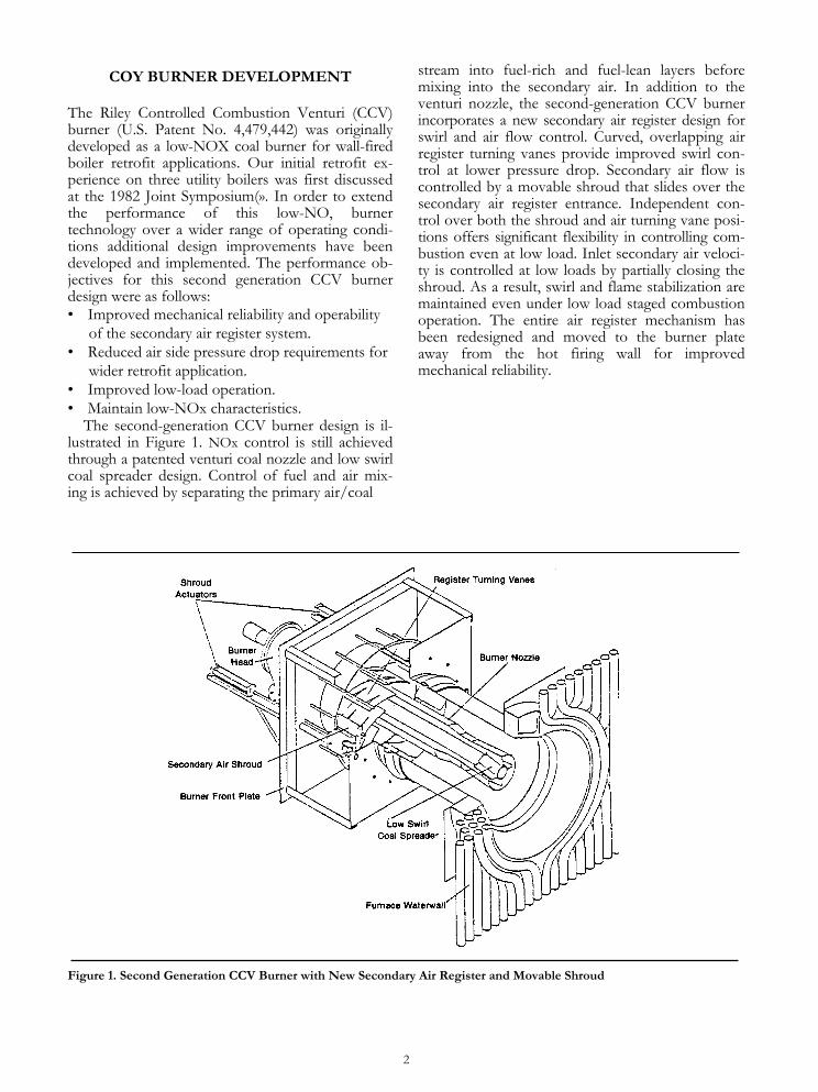
A 100 million Btu/hr prototype of this second-generation CCV burner has been built anddemonstrated in Riley Research's Coal Burner TestFacility (CBTF) located in Worcester,Massachusetts. This facility is designed to simulatenear field combustion conditions in full-scale fur-naces. A more complete description of this facilitywas presented at the 1985 Joint Symposium(2).Both staged and unstaged burner tests were con-ducted. Staged combustion was achieved by in-troducing a portion of the combustion airdownstream of the burner emissions with a Rileypre-NSPS Flare burner are shown in Figure 2. Inthese tests, primary or burner zone stoichiometrywas varied from 0.8 to 1.23 (unstaged). CCV burnerNOx emissions were 40 to 60 percent lower thanemission levels established with the Flare burner. Asfound in previous studies, NOx and CO emissionvaried with coal spreader configuration and theamount of overfire air. Spreader design, which con-trols flame length, allows the burner to be tuned tovarious tests. Scale-up of pilot-scale emission datato field conditions also depends on other con-sideration such as fuel type and furnace designparameters(3).
The following burner performance characteristicswere also established during the pilot-scale testing.:
• Turndown rate of 3 to 1• Combustion efficiency of 99.6 percent• A reduction in windox furnace pressure drop
from 8-10"wc to 4"wc• Improved mechanical reliabilitySecond generation CCV burners are now being
proposed drop for a number of utility and industrialboiler retrofit application both in the U.S. and FarEast.
NEW OVERFIRE AIR APPLICATIONRiley Stoker has retrofitted overfire air systems
on both coal and oil/gas fired boilers. A recent ap-plication included field modification to an existingoverfire air system on a 400MWe coal-fired Turbofurnace. This unit was designed in 1974 to meet the1971 NSPS of 0.7 lb/106 Btu. the objective of thefield modifications were: 1) increase boiler firingcapacity to 105-110 percent of maximum con-tinuous rating (MCR), 2) reduce NO, emissions to0.6 lb/106 Btu at 105 percent MCR, and 3) main-tain previous combustion efficiency at lower NOxoperation. An additional objective was to retain the
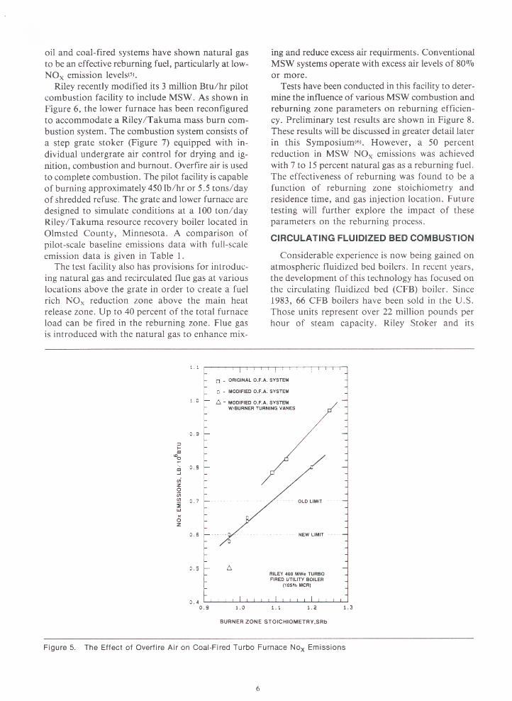
BURNER ZONE STOICHIOMETRY,SRb
20: t i 1 (~ I 1 . I I r 1. 1 1 I I f, II I , -T T " 0 CCV 15 DEG SPREADER q
CCV 30 DEG SPREADER-FLARE
40
20
I [ I t I t I l i l li l 1 1 1 1 1 1 1 1 1 1 1 1 1 1 1 ,
0.7 0.8 0.9 1.0 1.1 1.2 1.3
CCV 15 DEG SPREADER - U qCCV 30 DEG SPREADER -
A FLARE -
100 I t I t t I'1 1 1 I I 1 I 1 I I t l I i
140
120
100
80
60
Figure 2. Comparison of 100 Million Btulhr Pilot-Scale NOx and CO Emissions for the CCV and FlareBurners (open symbols Pennsylvania bituminous, solid symbols Illinois bituminous.
3
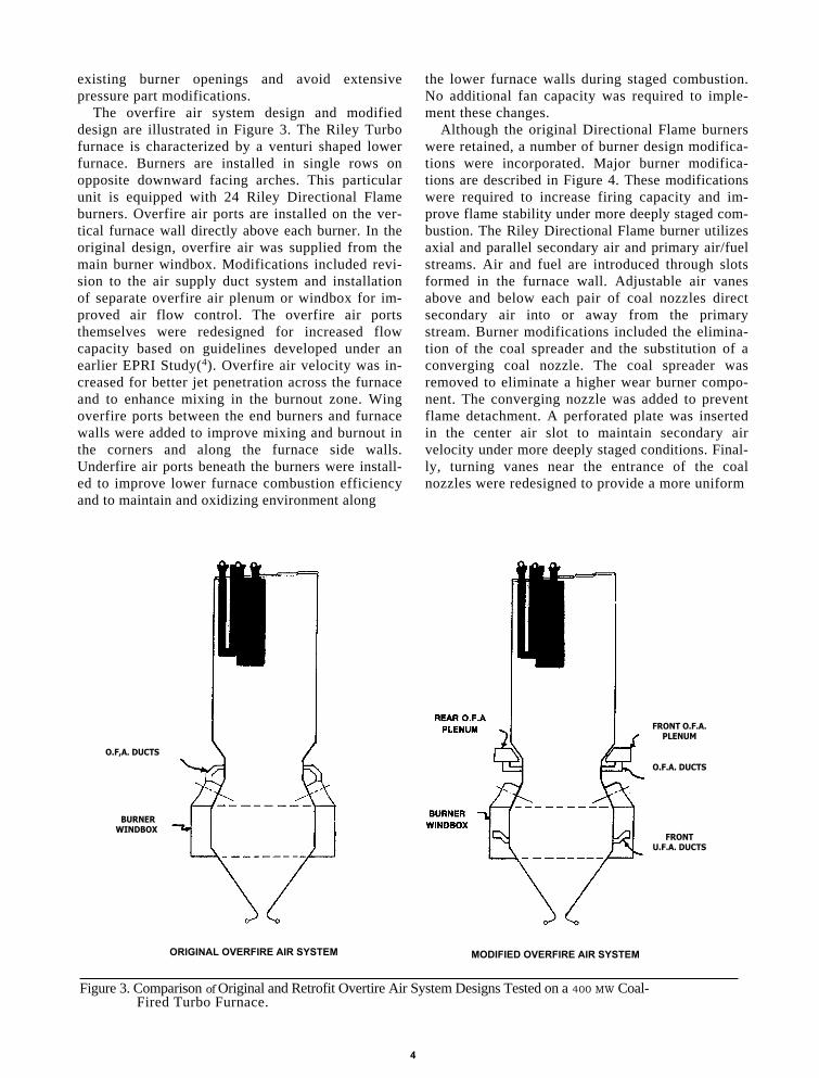
existing burner openings and avoid extensivepressure part modifications.
The overfire air system design and modifieddesign are illustrated in Figure 3. The Riley Turbofurnace is characterized by a venturi shaped lowerfurnace. Burners are installed in single rows onopposite downward facing arches. This particularunit is equipped with 24 Riley Directional Flameburners. Overfire air ports are installed on the ver-tical furnace wall directly above each burner. In theoriginal design, overfire air was supplied from themain burner windbox. Modifications included revi-sion to the air supply duct system and installationof separate overfire air plenum or windbox for im-proved air flow control. The overfire air portsthemselves were redesigned for increased flowcapacity based on guidelines developed under anearlier EPRI Study(4). Overfire air velocity was in-creased for better jet penetration across the furnaceand to enhance mixing in the burnout zone. Wingoverfire ports between the end burners and furnacewalls were added to improve mixing and burnout inthe corners and along the furnace side walls.Underfire air ports beneath the burners were install-ed to improve lower furnace combustion efficiencyand to maintain and oxidizing environment along
the lower furnace walls during staged combustion.No additional fan capacity was required to imple-ment these changes.
Although the original Directional Flame burnerswere retained, a number of burner design modifica-tions were incorporated. Major burner modifica-tions are described in Figure 4. These modificationswere required to increase firing capacity and im-prove flame stability under more deeply staged com-bustion. The Riley Directional Flame burner utilizesaxial and parallel secondary air and primary air/fuelstreams. Air and fuel are introduced through slotsformed in the furnace wall. Adjustable air vanesabove and below each pair of coal nozzles directsecondary air into or away from the primarystream. Burner modifications included the elimina-tion of the coal spreader and the substitution of aconverging coal nozzle. The coal spreader wasremoved to eliminate a higher wear burner compo-nent. The converging nozzle was added to preventflame detachment. A perforated plate was insertedin the center air slot to maintain secondary airvelocity under more deeply staged conditions. Final-ly, turning vanes near the entrance of the coalnozzles were redesigned to provide a more uniform
O.F,A. DUCTS
BURNERWINDBOX
ORIGINAL OVERFIRE AIR SYSTEM MODIFIED OVERFIRE AIR SYSTEM
FRONT O.F.A.PLENUM
O.F.A. DUCTS
FRONTU.F.A. DUCTS
Figure 3. Comparison of Original and Retrofit Overtire Air System Designs Tested on a 400 MW Coal-Fired Turbo Furnace.
4

distribution of primary air and fuel within the coalnozzle. The design of each of these coal nozzle com-ponents was based on the results of cold flow modelstudies.
All of the retrofit objectives were met. As shownin Figures 5, the original overfire air system design,while meeting NOx compliance at 100 percentMCR, did not provide an adequate amount of airstaging to achieve the compliance NOx level of 0.7lb/106 Btu at 105 percent MCR. However, fieldtesting demonstrated that the revised NOx limitemission of 0.6 lb/106 Btu is achieved with themodified overfire air system at 105 percent MCR.However, field testing demonstrated that the revisedNOx limit emission of 0.6 lb/6 Btu is achieved withthe modified overfire air system at 105 percentMCR. The addition of the redesigned coal pipe tur-ning vanes, described above, further enhancedoverall system NOx control capabilities. In additionto reducing NOx, these turning vanes also led tolower furnace exit gas temperature; thereby,eliminating the need for reheat spray above 100%MCR.
Carbon burnout did not deteriorate with the newsystem even under the higher load and low-NOx
operating conditions. However, in addition toburner modifications, mill system tuning was re-quired to maintain this level of performance. Thisfacility is equipped with three Riley ball tube millcoal pulverizers.
This case study emphasizes the importance of asystems approach when evaluating retrofit low-NOxcombustion control options. All aspects of thecombustion system must be considered including theburners overfire air ports, windbox, combustioncontrols, and pulverizer system.
NOx CONTROLS FOR MUNICIPALSOLID WASTE COMBUSTION
The Riley Research Center is currently engaged ina research and development program with the In-stitute of Gas Technology and the Gas Research In-stitute to reduce emissions from mass burn resourcerecovery boilers. The primary objective of this pro-gram is to determine the effectiveness of an in-furnace control technology known as reburning inreducing NOx formed during municipal solid waste(MSW) combustion. In this study natural gas isintroduced as a reburning fuel above a modernmass burn combustion grate. Pilot-scale studies on
Figure 4. Original and Modified Direction Flame Coal Burner
ORIGINAL BURNER DESIGN MODIFIED BURNER DESIGN
5
00
0
0 0
0 0 0
A
0 0
0 WITHOUT GAS REBURNING A
WITH GAS REBURNING
0
A
160
60
140120
100
80
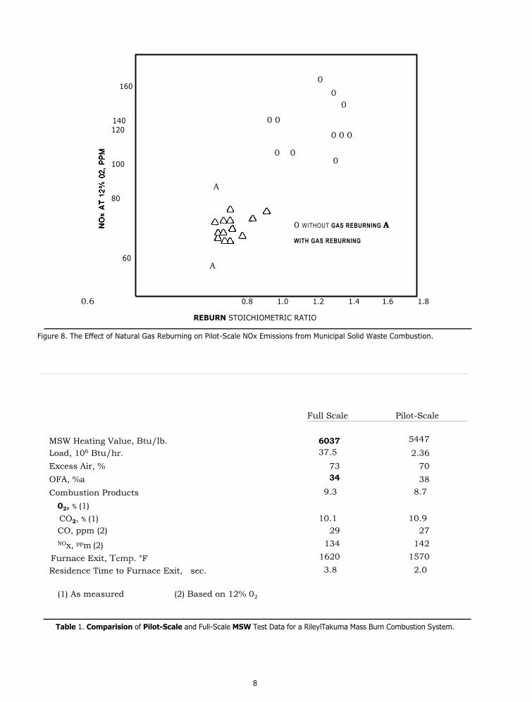
0.6 0.8 1.0 1.2 1.4 1.6 1.8
REBURN STOICHIOMETRIC RATIO
Figure 8. The Effect of Natural Gas Reburning on Pilot-Scale NOx Emissions from Municipal Solid Waste Combustion.
Full Scale Pilot-Scale
MSW Heating Value, Btu/lb. 6037 5447
Load, 106 Btu/hr. 37.5 2.36Excess Air, % 73 70OFA, %a 34 38Combustion Products
02, % (1)
9.3 8.7
CO2, % (1) 10.1 10.9CO, ppm (2) 29 27NOx, ppm (2) 134 142
Furnace Exit, Temp. °F 1620 1570
Residence Time to Furnace Exit, sec. 3.8 2.0
(1) As measured (2) Based on 12% 02
Table 1. Comparision of Pilot-Scale and Full-Scale MSW Test Data for a RileylTakuma Mass Burn Combustion System.
8

licensee, Mitsui Engineering and Shipbuilding Ltd.of Japan, have designed and constructed nine coal-fired CFB boilers varying in individual capacityfrom 150,000 to 660,000 lb/hr of steam. The Rileysystem is based on a technology known as Multi-solids Fluidized Bed Combustion (MSFBC)().
Riley coal-fired MSFBC boilers use limestone tocontrol SO2 emissions. MSFBC systems, therefore,are designed to operate at temperatures of 1500 to1700°F for efficient limestone utilization and SO2control. Each MSFB boiler incorporates stagedcombustion for enhanced NOx control. As aresult, NOx emissions from coal fired MSFBCunits are below current emission limits. Recent fieldtests in both the U.S. and Japan have demonstratedthat MSFBC boilers are capable of operating atNOx emission levels below 0.3 lb/106 Btu.Emiss-ions vary from unit to unit as a function of fuel typeand system design parameters such as primary zonestoichiometry, primary zone residence time, andtemperatures. In 1987, Riley Stoker was awarded aU.S. DOE contract to investigate advancedfluidized bed combustion concepts applicable tosmall coal-fired industrial and commercial boilers.
NOx emission levels of 0.1 lb/106 Btu or less withhigh combustion efficiency.
Riley Stoker is currently installing at its RileyResearch Center a 7 million Btu/hr circulatingfluidized bed test facility to study various stagedcombustion approaches. The combustor, shown inFigure 9, is over 60 feet tall and capable ofsimulating a variety of staged combustion con-figuration and operating conditions. Combustiontesting will begin this spring.
SUMMARY
Retrofit combustion controls in the form of low-NOX burners and improved overfire air systemsare commercially available. NOx reductions of upto 60 percent are possible with these technologies.A second-generation CCV burner has beendeveloped offering greater reliablity and extendedoperating range. Full-scale operating experience isstill required on more advanced combustion techni-ques, such as advanced air staging and reburning,before these technologies achieve commercialstatus.
Figure 9. Riley Stoker's 7 million Btulhr Pilot-Scale Circulating Fluidized Bed Test Facility
9
REFERENCES
1. R.A. Lisauskas and A.H, Rawdon, "Status ofNOX Controls for Riley Stoker Wall-Fired andTurbo-Fired Boilers," In: Proceedings of the1982 Joint Symposium on Stationary Combus-tion NOX Control, Vol. 1, EPRI CS-3182, July1983.
2. R. Lisauskas et al., "Experimental Investigationof Retrofit Low-NOX Combustion Systems," In:Proceedings: 1985 symposium on StationaryCombustion NOX Control, Vol. 1, EPRI CS-4360, January 1986.
3. R. Lisauskas, D. Itse and C. Masser, "Ex-trapolation of Burner Performance from SingleBurner Tests to Field Operation," In: Pro-ceedings: 1985 Symposium on Stationary com-bustion NOX Control, Vol. 1, EPRI CS-4360,January 1986.
4. R. Lisauskas, C. McHale, R. Afonso and D.Eskinazi, "Development of Overfire Air DesignGuidelines for Front-Fired Boilers," In Pro-ceedings: 1987 Symposium Stationary Combus-tion Nitrogen Oxide Control, Vol. 1, EPRI CS-5361, August 1987.
5. J. McCarthy et al., "Pilot-Scale Studies on theApplication of Reburning for NOX Control," InProceeding: 1987 Symposium StationaryCombustion Nitrogen Oxide Control, Vol. 1,EPRI CS-5361, August 1987.
6. C. Penterson, et al., "Reduction of NOX Emis-sions from MSW Combustion Using Gas Rebur-ning," Presented at the 1989 Joint Symposiumon Stationary Combustion NOX Control, SanFrancisco, March 1989.
7. W. Place and J. Coulthard, "Practical Aspects ofMulti-solid Fluid Bed (MSFB) Systems,"Presented at the Second International Con-ference Circulating Fluidized Beds, Campienge,France, March 1988.
8. R.W. Breault, "NOX Emissions from a StagedCirculation Fluidized Bed Combustion Process:The Multi-Solids Fluidized Bed Combustor,"Presented at the ASME Winter Annual Meeting,Boston, December 1987.
The Company reserves the right to make technical and mechanical changes or revisions resulting from improvements developed byits research and development work, or availability of new materials in connection with the design of its equipment, or improvements inmanufacturing and construction procedures and engineering standards.
10