rio algom mining llc - nrc: home page · rio algom mining llc certified mail - return receipt...
TRANSCRIPT
Rio Algom Mining LLC
CERTIFIED MAIL - RETURN RECEIPT REQUESTED - 7010 1870 0000 3700 2606
July 5, 2011
Jerry SchoeppnerNew Mexico Environment DepartmentHarold Runnels Building1190 St. Francis DrivePO Box 5469Santa Fe, NM 87502-5469
Subject: Rio Algom Mining LLC - Ambrosia LakeMonitoring Well Replacement Work Plan
Dear Jerry,
Rio Algom Mining LLC is please to submit the Monitor Well Replacement Work Plan thatproposes a solution the well integrity issues identified at the Ambrosia Lake site for NewMexico Environment Department comment, review and approval. Two copies areenclosed, additional copies (hard copy or electronic) can be made available at yourrequest.
Please review the Work Plan and let me know if you have any questions or if you needadditional information. Feel free to contact me at (505) 287-8851 ext 19 or by e-mail at
Respectfully submitted,
.,-
Billy Rai..Ambrosia Lake Site Manager
Enclosures - As Noted
P.O. Box 218. Grants, NM USA 87020 - Tel: 505.287.8851 - Fax: 505.285.5550
MONITORING WELL REPLACEMENTWORK PLANRIO ALGOM MINING, LLC
Submitted to:Mr. Billy RaySite ManagerRio Algom Mining, LLC
Submitted by:
InLN~miz6000 Uptown Boulevard NE, Suite 220Albuquerque, New Mexico 87110
June 30, 2011
ifl ni: A
TABLE OF CONTENTS
LIST OF FIGURES .................................................................. I A
LIST O F TA BLES ........................................................................................................................ ii
LIST O F A PPEN D IC ES .............................................................................................................. ii
1.0 IN TR O D U C T IO N ................................................................................................................. 1
1.1. Project Background .................................................................................................. 1
2.0 SC O PE O F W O R K ....................................................................................................... 2
2.1. Task 1: Project Planning and Scheduling .............................................................. 22.1.1. Personnel ...................................................................................................... 2
2.2. Task 2: Monitoring Well Installation, Development, and Abandonment ............ 32.2.1. A lluvial M onitoring W ells ........................................................................... 42.2.2. Confined A quifer M onitoring W ells ............................................................. 52.2.3. W ell D evelopm ent ....................................................................................... 72.2.4. W ell A bandonm ent ....................................................................................... 72.2.5. Activities Supporting Well Installation and Abandonment .......................... 7
2.3. Task 3: Project Report Preparation ...................................................................... 8
3.0 SC H ED U LE ........................................................................................................................... 9
.Monitoring Well Replacement Work PlanRio Algom Mining, LLC June 30, 2011
IfliE~A
LIST OF FIGURES
Figure 1Figure 2Figure 3
Table 1
Site Plan, Well ReplacementProposed Alluvial Monitoring Well Construction DetailMonitoring Well Construction Schematic, Dakota Formation Confined Aquifer
LIST OF TABLES
Existing Well Construction Detail and Proposed Replacement Depth
LIST OF APPENDICES
New Mexico Environment Department Ground Water Quality Bureau MonitoringWell Construction and Abandonment GuidelinesRules and Regulations Governing Well Driller Licensing; Construction, Repairand Plugging of WellsNMED Monitoring Well Construction RequirementsWell Permit Application Form, Example of Completed Well Permit ApplicationForm, Well Plugging Plan of Operations Form, and Plugging Record Form
Appendix A
Appendix B
Appendix CAppendix D
Monitoring Well Replacement Work PlanRio Algom Mining, LLC ii June 30, 2011
INTRODUCTION
This work plan describes the methods that will be used to abandon 14 existing monitoring wellsand install 12 new monitoring wells on property that belongs to Rio Algom Mining, LLC(RAML) (Site). A Site plan showing the well locations is provided in Figure 1. This work planwas prepared in response to a request from Mr. Billy Ray, Site Manager for RAML, to Dr. DanErskine of INTERA Incorporated (INTERA) in December 2010.
The purpose of the project is to:
1. Abandon 12 monitoring wells and replace them with 12 new monitoring wells.
2. Abandon 2 monitoring wells (but not replace them with new wells).
As illustrated on Figure 1, the wells to be abandoned and replaced are MW 30-04, MW 30-48 KD,MW 31-05, MW 32-01, MW 32-02, MW 30-68, MW 31-70, MW 5-03, MW 5-08, MW 5-73,MW 32-45 KD, and MW 3 1-01 TRA. The wells to be abandoned only are MW 30-03 andMW 32-50. Table 1 provides the existing construction design details for all of these wells basedon information provided by RAML. The column titled "Replacement Target Depth" in Table 1provides the proposed depth of the replacement wells, based on the RAML-documented depth ofthe alluvial/bedrock interface, tabulated data, and well construction diagrams.
The rest of this section provides project background information, Section 2.0 details the scope ofwork and includes a description of the well installation and abandonment procedures, andSection 3.0 discusses the project schedule.
1.1. Project Background
At the request of the New Mexico Environment Department (NMED), RAML performed areview of DP-169 monitoring wells. The review included inspection of original well-completion
records for total depth of each well and a comparison to the current measured depth of eachwell. Wells that were significantly shallower than indicated by well-completion records wereselected for replacement. The review also included a physical inspection of each well, and wellsthat had visible integrity issues, such as a broken casing or screen, were also selected forreplacement.
The 14 monitoring wells to be abandoned have been used to monitor groundwater elevation andgroundwater chemistry as part of the Site groundwater monitoring program (Figure 1). Thewells range in depth from approximately 35 feet (ft) to more than 350 ft below ground surfaceand are sampled periodically by the RAML field sampling team. These monitoring wells were
Monitoring Well Replacement Work PlanRio Algom Mining, LLC 1 June 30, 2011
constructed in the 1960s and 1970s. The proposed new monitoring wells will be constructedaccording to current industry standards as described in Sections 2.2.1 and 2.2.2.
The differences in the well depths reflect the different monitoring objectives. Nine of the wells aredesigned to monitor groundwater in the alluvium, while wells MW 30-48 KD and MW 32-45 KDmonitor groundwater in the Dakota Formation. Well MW 5-08 monitors groundwater in both thealluvium and the Tres Hermanos "B" member of the Mancos Shale, although the Tres Hermanos"B" is generally considered to be dry. The alluvial wells are considered to be water table wells(i.e., monitoring the first water encountered in the subsurface), while the aquifers monitored bythe other wells may be confined (i.e., separated from the water table by a geologic barrier andunder pressure). The drilling and installation of the alluvial wells is relatively simple. However,the wells in the confined aquifers will be drilled and constructed according to NMED and NewMexico Office of the State Engineer (OSE) requirements, as well as best professional practice,with the objective of maintaining separation between the alluvial groundwater and the
groundwater in the confined zones.
2.0 SCOPE OF WORK
INTERA has divided the project scope of work into the following three tasks:
" Task 1 - Project Planning and Scheduling
" Task 2 - Monitoring Well Installation, Development, and Abandonment
" Task 3 - Project Report Preparation
This work plan is part of Task 1.
2.1. Task 1: Project Planning and Scheduling
This task includes project planning and scheduling activities for monitoring well installation anddevelopment and abandonment of the old wells. Prior to any drilling, INTERA will coordinatewith New Mexico One Call and/or RAML to identify and mark any underground or overhead
utilities.
2.1.1. Personnel
The key personnel who will be responsible for completion of the project are listed below alongwith their areas of responsibility.
Monitoring Well Replacement Work PlanRio Algom Mining, LLC 2 June 30, 2011
In E A
Ms. Cindy Ardito, Principal Ms. Ardito will provide client interface andwill review deliverables. She will beresponsible for INTERA resource allocation.
Dr. Daniel Erskine, Project Manager Dr. Erskine will provide senior technicaloversight as needed.
Mr. Robert Sengebush, PG, Principal Geologist Mr. Sengebush will serve as field manager.Mr. Sengebush has extensive experiencedesigning and installing monitoring wells inwater table and confined aquifers.
Mr. Lee Dalton, Staff Geologist Mr. Dalton will oversee field activities anddevelopment of wells at the Site.
2.2. Task 2: Monitoring Well Installation, Development, and Abandonment
Twelve well borings will be drilled to the approximate depths shown in Table 1. The alluvial
wells will be drilled to whatever depth is necessary to (1) ensure that at least 20 ft of alluvial
groundwater is present (if possible) in the wells when they are installed, and (2) account forpotential future lowering of the groundwater elevation in the alluvium. However, the new
alluvium well depths will not be deeper than the base of the alluvium. The base of the alluviumwill be "picked" based on information provided by RAML in previous well logs and/or based on
the geologic logging of cuttings as the well bore is drilled. INTERA expects that the
alluvial/bedrock interface will be apparent in the cuttings as a change from unconsolidated sand
or gravel to a consolidated bedrock shale (Mancos) or cemented sandstone (Tres Hermanos). Ifthe replacement alluvium wells are dry at the interface of the alluvium and the underlying
bedrock, this will be considered an acceptable outcome, as it will demonstrate that groundwateris not present in the alluvium at that location.
The Dakota and Tres Hermanos "A" wells may be drilled to approximately the same depths as
the existing wells. The wells will be drilled using air-rotary, hollow-stem auger, or sonic drillingequipment. The actual drilling method will be selected based on information and bids obtainedfrom drilling contractors. The confined aquifer wells will be constructed with a conductor casing
cemented across the alluvium to maintain separation between the groundwater in the alluvialaquifer and groundwater in the confined Dakota Formation and Tres Hermanos "A" aquifers.Drilling details are provided in Sections 2.2.1 and 2.2.2 below.
An INTERA representative will be on-site to oversee drilling activities, log the boreholelithology, and oversee monitoring well installation and development. Soil cuttings generated
during drilling will be thin-spread on the Site or containerized and placed in the proper disposal
Monitoring Well Replacement Work PlanRio Algom Mining, LLC 3 June 30, 2011
IflhE:z1
cell on the RAML facility, such as Pond 2. A select portion of the cuttings will be bagged,labeled, and stored for future inspection by NMED. All downhole equipment will bedecontaminated prior to and between each well boring event using environmental industrystandard procedures. Decontamination consists of pressure wash and/or steam cleaning of drillbits, drive casing, and drill rods or other down-hole drilling tools using potable water.
INTERA will prepare the drilling specifications and bid request and obtain the drilling contract(through INTERA) as requested by RAML. INTERA will obtain three drilling bids and selectthe drilling subcontractor that represents the combination of capability and cost that is mostadvantageous to RAML.
2.2.1. Alluvial Monitoring Wells
The objective of the alluvial monitoring wells is to monitor the groundwater in the alluvialinterval within the 20 ft directly above the alluvium-bedrock interface. The alluvial monitoringwell depths vary because the thickness of the alluvium varies across the Site. MW 32-50, whichmonitors the boundary between the alluvium and the Tres Hermanos "B" zone, is grouped withthe alluvial monitoring wells because in that well the alluvium has scoured into the TresHermanos "B" such that water in that zone (if any) is in communication with the water tableaquifer.
The monitoring wells will be designed and constructed according to New Mexico requirements(http://www.n-nciv.statc.1m.us/gwb/docuincits/MonitoringWelGGuideliniesFINAL-March20 I .pdf,New Mexico Environment Department Ground Water Quality Bureau Monitoring Well
'Construction and Abandonment Guidelines, provided in Appendix A of this work plan). Aschematic diagram of an alluvial monitoring well is provided in Figure 2. Monitoring wellpermits (called "Application for Permit to Drill an Exploratory Well") are obtained from theOSE and are described in more detail in Section 2.2.5 of this work plan.
The alluvial aquifer monitoring well boreholes will be drilled to a nominal 8-inch diameter usinga dry drilling system, such as air-rotary or other functionally equivalent drilling method. Soilsamples will be collected every 10 ft and described (logged) by the field geologist. Eachborehole will be converted to a 4-inch polyvinyl chloride (PVC), flush-threaded, schedule 80well with 20 ft of 0.010-inch slot screen with an end cap and blank casing to the surface. Thewell casing will extend 3 ft above the ground surface. Each well will be backfilled with 10/20sand (filter pack) to 2 ft above the top of the well screen, followed by 5 ft of transitional 20/40(finer-grained) sand. Five (5) ft of hydrated bentonite chips or pellets will then be placed abovethe sand pack followed by cement/bentonite (97%/3% by volume) grout to 3 ft below grade.Concrete will then be used to backfill the remaining 3 ft and construct a 2-foot by 2-foot by 4-
Monitoring Well Replacement Work PlanRio Algom Mining, LLC 4 June 30, 2011
Irl E:A
inch thick surface pad. A steel protective casing with a locking, hinged lid will be installed over
the PVC well casing. This casing will be surrounded by four protective traffic posts emplaced in
the concrete approximately 3 ft above ground. The location and elevation at top of casing of themonitoring wells PVC casing measuring point will be surveyed. The measuring point will be marked
on the north side of the PVC casing.
Each new monitoring well will be developed using surging and bailing techniques. The turbidityof the produced groundwater will be qualitatively monitored and recorded during development,
and the water quality parameters (pH, specific conductance, and temperature) will. be measured.Development water will be discharged to an on-site surface and allowed to evaporate.
INTERA anticipates that the well-installation activities for the alluvial wells can be completed in
a period of no more than 20, 10-hour working days, weather and field conditions permitting.
2.2.2. Confined Aquifer Monitoring Wells
The Dakota Formation wells, MW 30-48 KD and 32-42KD, and the Tres Hermanos "A" well,
MW 31-01, will be constructed to maintain the separation between the alluvial and confined
Dakota (or Tres Hermanos) aquifers, as required by New Mexico well construction regulations(http://www.ose.state.nm.us/doing-business/Well I)rillerRegs/WellDri llerR.ulesR.egs-2005-08-3 I.pd f,
19.27.4.31), provided in Appendix B of this work plan and in a schematic diagram of the
confined aquifer monitoring well (Figure 3). These OSE regulations specifically address"artesian" wells (those that may "flow uncontrolled to the land surface or move appreciably
between geologic units") and apply to the wells constructed in the Dakota and Tres Hermanos
Formations.
The Dakota and Tres Hermanos "A" aquifers are known to be confined aquifers, and the
potentiometric surfaces of these aquifers may rise somewhat above the top of the formations,although the flow is not expected to reach the ground surface. Also, it is clear that aquifer
conditions can change over time and may be different depending on the location of the well. A
completion of the new MW 32-45 KD well with depth dimensions similar to those of the existingwell (total depth approximately 270 ft) should provide sufficient water for sampling (currently
the water column in this well is 24 ft, according to data provided by RAML). MW 30-48 KD, on
the other hand, has a total depth of 351 ft and is dry, suggesting that there is a significantdifference in the Dakota aquifer conditions between the two wells (located approximately4,800 ft apart) or that well damage is preventing water entry. According to the lithologic log of
this well provided by RAML, the Dakota is approximately 80 fl thick, the base is at 345 ft, andthe well is screened from 331 to 351 ft, but the well is currently dry. It is anticipated that the
Monitoring Well Replacement Work PlanRio Algom Mining, LLC 5 June 30, 2011
drilling depths and screen intervals in the three confined aquifer replacement wells will be
essentially equivalent to those of the existing wells.
The Dakota (two wells) and Tres Hermanos "A" (one well) wells will be drilled using air rotary
drilling equipment or a functionally equivalent dry drilling method. Drilling these wells dry (i.e.,
without drilling mud or other wet drilling fluid) will ensure that the target aquifer formations are
not damaged by drilling fluids and will reduce the amount of effort required to develop the wells.
Geologic logging will be done by observation and description of the cuttings brought to the
surface during drilling. The geologic logging of these cuttings, along with the design dimensions
of the existing wells, will be the basis for the selection of the replacement well total depths and
screened intervals.
The process will begin by drilling a boring for installation of a steel casing (conductor casing)
cemented into place approximately 5 ft into the top of the formation (Dakota or Tres Hermanos),
effectively sealing off the alluvial aquifer from the confined aquifer. The cased hole will be
extended with a smaller diameter boring to the base of the target formation. The monitoring well
will be built inside the conductor casing and completed according to the standard well
construction methods, as shown in Figure 3.
The inner well will be constructed of schedule 80 PVC casing, with 20 ft of 0.010-inch slotted
PVC screen and a 10/20 sand filter pack. The well will be sealed with a bentonite seal and
grouted to near the ground surface using cement/bentonite (97%/3% by volume) grout. The well
will be finished with an above-ground surface completion, a cement pad, a locking protective
casing, and protective traffic posts. The top of the inner casing will be surveyed for location and
elevation so that the groundwater elevation may be measured.
Boring and casing dimensions and other specifications will be determined in consultation with
the RAML technical staff and the drilling contractor. The conductor casing will need to be of
sufficient diameter to accommodate the inner casing, and the equipment required to emplace the
sand pack, seal and grout, inner casing, and screen will need to have a large enough diameter to
accommodate the pumping equipment used by the RAML field staff to purge and sample the
well. The existing wells were completed with a 6-inch inner-diameter conductor casing and a 4-
inch diameter well casing and screen. This basic design may be used for the replacement wells.
The confined aquifer wells are expected to take up to a week each to complete, due to the greater
depth (compared with the alluvial wells) and the requirement for installation and cementing of
the conductor casing.
Monitoring Well Replacement Work PlanRio Algom Mining, LLC 6 June 30, 2011
Additional information regarding drilling and completion of the confined aquifer monitoringwell may be found on the NMED website (http://www.nmenv.state.nni.us/hwb/docunlentsiAtt_19.pdt) and in Appendix C of this work plan.
2.2.3. Well DevelopmentThe monitoring wells will be developed using standard development methods, including bailing,surging, jetting, airlifting, and pumping, until the water is free of sand or silt, according to thejudgment of the field geologist. Development water will be disposed of on the ground surfaceunless other water disposal methods are required.
The well development may require up to several hours per well plus mobilization ofdevelopment equipment from well to well. The development will be accomplished using aseparate "development rig" after all of the monitoring wells are completed.
2.2.4. Well Abandonment
The 14 existing monitoring wells will be plugged and abandoned according to NMED and OSErequirements as described in the New Mexico Environment Department Ground Water QualityBureau Monitoring Well Construction and Abandonment Guidelines (March 201 1), included in
Appendix A. The NMED abandonment guidelines state, "12. Approval for abandonment ofmonitoring wells used for ground water monitoring in accordance with Discharge Permit andAbatement Plan requirements must be obtained from NMED prior to abandonment."
The abandonment task will be conducted by a subcontractor under the supervision of anINTERA field geologist. Prior to the abandonment, the "Well Plugging Plan of Operations" form(http://www.osc.statc.nm.us/watcrhinfo_riglhts_drillersforms.html) must be completed andsubmitted to the OSE. A copy of this form is provided in Appendix D.
The procedure will consist of pulling out as much of the old casing as possible, or overdrillingthe old well casing and seal to clean out the old borehole. The cleaned borehole will then befilled with cement grout to the surface, according to the NMED Monitoring Well ConstructionRequirements (November 2009), presented in Appendix C of this work plan. Notice of theabandonment, which consists of completing the OSE "Plugging Record" form(http://www.ose.state.'nm.us/water inib-rights-drillers -Forms .html), must be provided to OSEand NMED. A copy of this form is provided in Appendix D.
2.2.5. Activities Supporting Well Installation and AbandonmentActivities that will be performed as part of the well installation and abandonment task include:
Monitoring Well Replacement Work PlanRio Algom Mining, LLC 7 June 30, 2011
1. Submit applications for monitoring well permits to the OSE. A copy of a well permitapplication form is included in Appendix D of this work plan and may be found on thefollowing website: http://www.ose.state.nin.us/doing-busincss/fonms-inst/wr-fonns-inst.htrnl. Although the form is titled "Application for Permit to Drill an ExploratoryWell," it is the correct form to use for monitoring wells. A fee of $5.00 per well isrequired. An example of a completed and approved form is included in Appendix D.INTERA will complete the forms and begin the permitting process at the time ofsubmission of this work plan to RAML. The OSE review and approval period may takeseveral weeks.
2. Complete and submit the "Well Plugging Plan of Operations" form to OSE. A copy ofthe form is provided in Appendix D.
3. Complete and submit the "Plugging Record" form to OSE and NMED as a record of theabandonment. A copy of the form is provided in Appendix D.
4. Contact New Mexico One Call prior to drilling to arrange for identification and markingof underground utilities.
5. Coordinate with RAML management to identify any potential underground or overheadutilities.
6. Review and update, if necessary, the Site-specific health and safety plan.
Well abandonment will be accomplished using a crew and equipment that is separate from thedrilling operations. Abandonment may require up to a day per location, depending on well depth,type and condition of the existing casing, etc.
2.3. Task 3: Project Report Preparation
Upon completion of Task 2, INTERA will prepare a report documenting the methods andoutcome of the well abandonment and installation program. The report will include at aminimum:
* A written description of field activities.
" A Site map showing the well locations.
" Geologic logs and well-construction diagrams.
" Well-abandonment documentation consisting of the "Well Plugging Plan of Operations"
form, the "Plugging Record" form, notification to NMED, etc.
" Photographic documentation of field activities.
Monitoring Well Replacement Work PlanRio Algom Mining, LLC 8 June 30, 2011
Ifl~E~A
3.0 SCHEDULE
INTERA will begin scheduling and project-coordination activities as soon as possible uponreceipt of authorization to proceed from RAML. The work is estimated to be completed in fourmonths, including permitting, field work, and report preparation.
Monitoring Well Replacement Work PlanRio Algom Mining, LLC 9 June 30, 2011
APPENDIX ANew Mexico Environment Department
Ground Water Quality BureauMonitoring Well Construction and Abandonment Guidelines
NEW MEXICO ENVIRONMENT DEPARTMENTGROUND WATER QUALITY BUREAU
MONITORING WELL CONSTRUCTION AND ABANDONMENT GUIDELINES
Purpose: These guidelines identify minimum construction and abandonment details for installation ofwater table monitoring wells under ground water Discharge Permits issued by the NMED's Ground WaterQuality Bureau (GWQB) and Abatement Plans approved by the GWQB. Proposed locations ofmonitoring wells required under Discharge Permits and Abatement Plans and requests to use alternateinstallation and/or construction methods for water table monitoring wells or other types of monitoringwells (e.g., deep monitoring wells for delineation of vertical extent of contaminants) must be submitted tothe GWQB for approval prior to drilling and construction.
General Drilling Specifications:
1. All well drilling activities must be performed by an individual with a current and valid well drillerlicense issued by the State of New Mexico in accordance with 19.27.4 NMAC. Use of drillers withenviromnental well drilling experience and expertise is highly recommended.
2. Drilling methods that allow for accurate determinations of water table locations must be employed.All drill bits, drill rods, and down-hole tools must be thoroughly cleaned immediately prior to the startof drilling. The borehole diameter must be drilled a minimum of 4 inches larger than the casingdiameter to allow for the emplacement of sand and sealant.
3. After completion, the well should be allowed to stabilize for a minimum of 12 hours beforedevelopment is initiated.
4. The well must be developed so that formation water flows freely through the screen and is not turbid,and all sediment and drilling disturbances are removed from the well.
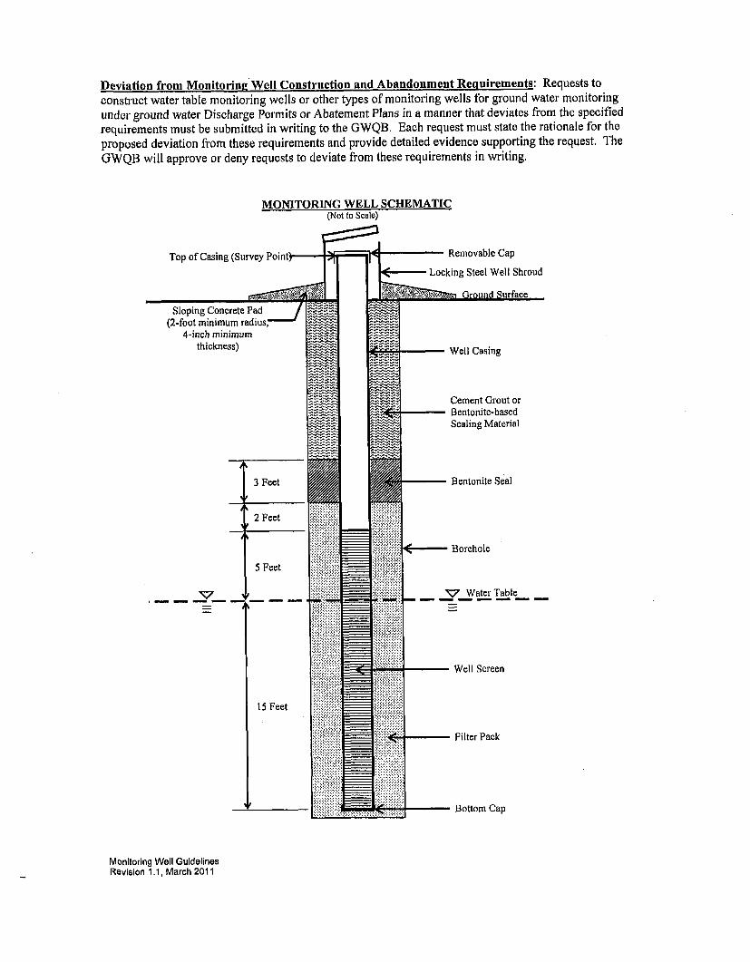
Well Specifications (see attached monitoring well schematic):
5. Schedule 40 (or heavier) polyvinyl chloride (PVC) pipe, stainless steel pipe, carbon steel pipe, or pipeof an alternate appropriate material that has been approved for use by NMED must be used as casing.The casing must have an inside diameter not less than 2 inches. The casing material selected for usemust be compatible with the anticipated chemistry of the ground water and appropriate for thecontaminants of interest at the facility. The casing material and thickness selected for use must havesufficient collapse strength to withstand the pressure exerted by grouts used as annular seals andthermal properties sufficient to withstand the heat generated by the hydration of cement-based grouts.Casing sections may be joined using welded, threaded, or mechanically locking joints; the methodselected must provide sufficient joint strength for the specific well installation. The casing mustextend from the top of the screen to at least one foot above ground surface. The top of the casingmust be fitted with a removable cap, and the exposed casing must be protected by a locking steel wellshroud. The shroud must be large enough in diameter to allow easy access for removal of the cap.Alternatively, monitoring wells may be completed below grade. In this case, the casing must extendfrom the top of the screen to 6 to 12 inches below the ground surface; the monitoring wells must besealed with locking, expandable well plugs; a flush-mount, watertight well vault that is rated towithstand traffic loads must be emplaced around the wellhead; and the cover must be secured with atleast one bolt. The vault cover must indicate that the wellhead of a monitoring well is containedwithin the vault.
6. A 20-foot section (maximum) of continuous-slot, machine slotted, or other manufactured PVC orstainless steel well screen or well screen of an alternate appropriate material that has been approvedfor use by NMED must be installed across the water table. Screens created by cutting slots into solidcasing with saws or other tools must not be used. The screen material selected for use must becompatible with the anticipated chemistry of the ground water and appropriate for the contaminantsof interest at the facility. Screen sections may be joined using welded, threaded, or mechanically
Monitoring Well GuidelinesRevision 1.1, March 2011
locking joints; the method selected must provide sufficient joint strength for the specific wellinstallation and must not introduce constituents that may reasonably be considered contaminants ofinterest at the facility. A cap must be attached to the bottom of the well screen; sumps (i.e., casingattached to the bottom of a well screen) should not be installed. The bottom of the screen must beinstalled no more than 15 feet below the water table; the top of the well screen must be positioned notless than 5 feet above the water table. The well screen slots must be appropriately sized for theformation materials and should be selected to retain 90 percent of the filter pack. A slot size of 0.010inches is generally adequate for most installations.
7. Casing and well screen must be centered in the borehole by placing centralizers near the top andbottom of the well screen.
8. A filter pack must be installed around the screen by filling the annular space from the bottom of thescreen to 2 feet above the top of the screen with clean silica sand. The filter pack must be properlysized to prevent fine particles in the formation from entering the well; clean medium to coarse silicasand is generally adequate as filter pack material for 0.010-inch slotted well screen. For wells deeperthan 30 feet, the sand must be emplaced by a tremmie pipe. The well should be surged or bailed tosettle the filter pack and additional sand added, if necessary, before the bentonite seal is emplaced.
9. A bentonite seal must be constructed immediately above the filter pack by emplacing bentonite chipsor pellets (3/8-inch in size or smaller) in a manner that prevents bridging of the chips/pellets in theannular space. The bentonite seal must be 3 feet in thickness and hydrated with clean water.Adequate time should be allowed for expansion of the bentonite seal before installation of the annularspace seal.
10. The annular space above the bentonite seal must be sealed with cement grout or a bentonite-basedsealing material acceptable to the State Engineer pursuant to 19.27.4 NMAC. A tremmie pipe mustbe used when placing sealing materials at depths greater than 20 feet below the ground surface.Annular space seals must extend from the top of the bentonite seal to the ground surface (for wellscompleted above grade) or to a level 3 to 6 inches below the top of casing (for wells completed belowgrade).
11. For monitoring wells finished above grade, a concrete pad (2-foot minimum radius, 4-inch minimumthickness) must be poured around the shroud and wellhead. The concrete and surrounding soil mustbe sloped to direct rainfall and runoff away from the wellhead. The installation of steel posts aroundthe well shroud and wellhead is recommended for monitoring wells finished above grade to protectthe wellhead from damage by vehicles or equipment. For monitoring wells finished below grade, aconcrete pad (2-foot minimum radius, 4-inch minimum thickness) must be poured around the wellvault and wellhead. The concrete and surrounding soil must be sloped to direct rainfall and runoffaway from the well vault.
Abandonment:
12. Approval for abandonment of monitoring wells used for ground water monitoring in accordance withDischarge Permit and Abatement Plan requirements must be obtained from NMED prior toabandonment.
13. Well abandonment must be accomplished by removing the well casing and placing neat cementgrout, bentonite-based plugging material, or other sealing material approved by the State Engineer forwells that encounter water pursuant to 19.27.4 NMAC from the bottom of the borehole to the groundsurface using a tremmie pipe. If the casing cannot be removed, neat cement grout, bentonite-basedplugging material, or other sealing material approved by the State Engineer must be placed in thewell using a tremmie pipe from the bottom of the well to the ground surface.
14. After abandonment, written notification describing the well abandonment must be submitted to theNMED. Written notification of well abandonment must consist of a copy of the well plugging recordsubmitted to the State Engineer in accordance with 19.27.4 NMAC, or alternate documentationcontaining the information to be provided in a well plugging record required by the State Engineer asspecified in 19.27.4 NMAC.
Monitoring Well GuidelinesRevision 1.1, March 2011
Deviation from Monitoring Well Construction and Abandonment Requirements: Requests toconstruct water table monitoring wells or other types of monitoring wells for ground water monitoringunder ground water Discharge Permits or Abatement Plans in a manner that deviates from the specifiedrequirements must be submitted in writing to the GWQB. Each request must state the rationale for theproposed deviation from these requirements and provide detailed evidence supporting the request. TheGWQB will approve or deny requests to deviate from these requirements in writing.
MONITORING WELL SCHEMATIC(Not to Scale)
Top of Casing (Survey Point)-
Sloping Concrete Pad
(2-foot minimum radius,'4-inch minimum
thickness)
3 Feet
2 Feet
Removable Cap
on Ground Surface
_ _ Well Casing
Cement Grout or-Bentonite-based
Scaling Material
- Bentonite Seal
E- Borehole
5 Feet
' Water Table
- Well Screen
15 Feet
Filter Pack
- Bottom Cap
Monitoring Well GuidelinesRevision 1.1, March 2011
APPENDIX BRules and Regulations Governing Well Driller Licensing;
Construction, Repair and Plugging of Wells
RULES AND REGULATIONS
GOVERNING WELL DRILLER LICENSING;
CONSTRUCTION, REPAIR AND PLUGGING OF
WELLS
V .:: • ~ .•i,••i••..... .: =:I••:=:
Adopted August 31. 2005
John R. D'Antonio, Jr., PE
State Engineer
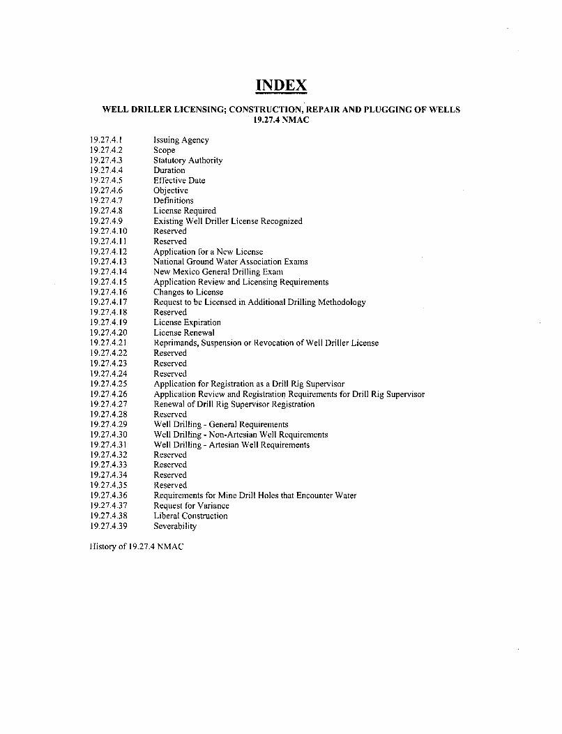
INDEX
WELL DRILLER LICENSING; CONSTRUCTION, REPAIR AND PLUGGING OF WELLS19.27.4 NMAC
19.27.4.1 Issuing Agency19.27.4.2 Scope19.27.4.3 Statutory Authority19.27.4.4 Duration19.27.4.5 Effective Date19.27.4.6 Objective19.27.4.7 Definitions19.27.4.8 License Required19.27.4.9 Existing Well Driller License Recognized19.27.4.10 Reserved19.27.4.11 Reserved19.27.4.12 Application for a New License19.27.4.13 National Ground Water Association Exams19.27.4.14 New Mexico General Drilling Exam19.27.4.15 Application Review and Licensing Requirements19.27.4.16 Changes to License19.27.4.17 Request to be Licensed in Additional Drilling Methodology19.27.4.18 Reserved19.27.4.19 License Expiration19.27.4.20 License Renewal19.27.4.21 Reprimands, Suspension or Revocation of Well Driller License19.27.4.22 Reserved19.27.4.23 Reserved19.27.4.24 Reserved19.27.4.25 Application for Registration as a Drill Rig Supervisor19.27.4.26 Application Review and Registration Requirements for Drill Rig Supervisor19.27.4.27 Renewal of Drill Rig Supervisor Registration19.27.4.28 Reserved19.27.4.29 Well Drilling - General Requirements19.27.4.30 Well Drilling - Non-Artesian Well Requirements19.27.4.31 Well Drilling - Artesian Well Requirements19.27.4.32 Reserved19.27.4.33 Reserved19.27.4.34 Reserved19.27.4.35 Reserved19.27.4.36 Requirements for Mine Drill Holes that Encounter Water19.27.4.37 Request for Variance19.27.4.38 Liberal Construction19.27.4.39 Severability
History of 19.27.4 NMAC
TITLE 19 NATURAL RESOURCES AND WILDLIFECHAPTER 27 UNDERGROUND WATERPART 4 WELL DRILLER LICENSING; CONSTRUCTION, REPAIR AND PLUGGING OF
WELLS
19.27.4.1 ISSUING AGENCY: Office of the State Engineer.[19.27.4.1 NMAC - N, 8-31-2005]
19.27.4.2 SCOPE: The rules for well driller licensing, drill rig supervisor registration, and well drillingwithin the state of New Mexico. These rules also apply to mine drill holes that encounter water. These rules do notapply to oil wells, gas wells, or cathodic protection wells.[19.27.4.2 NMAC - N, 8-31-2005]
19.27.4.3 STATUTORY AUTHORITY: Section 72-12-1 NMSA provides that the water of undergroundstreams, channels, artesian basins, reservoirs, or lakes having reasonably ascertainable boundaries are declared to bepublic waters which belong to the public and are subject to appropriation for beneficial use. Section 72-2-8 NMSAgives the state engineer authority to adopt regulations and codes to implement and enforce any provision of any lawadministered by him. Section 72-12-12 NMSA states that it shall be unlawful for any person, firm, or corporation todrill or to begin the drilling of a well for water from an underground source without a valid, existing license for thedrilling of such wells issued by the state engineer of New Mexico, Section 72-12-13 NMSA states any persondesiring to engage in the drilling of one or more wells for underground water within the boundaries of anyunderground source shall file an applicationwith the state engineer for a driller license. Sections 72-12-14 through72-12-17 NMSA further detail requirements for well drillers in New Mexico. Sections 72-13-1 through 72-13-12NMSA detail the requirements for the drilling of artesian wells.[19.27.4.3 NMAC - N, 8-31-2005]
19.27.4.4 DURATION: Permanent.[ 19.27.4.4 NMAC - N, 8-31-2005]
19.27.4.5 EFFECTIVE DATE: August 31, 2005, unless a later date is cited at the end of a section.[19.27.4.5 NMAC - N, 8-31-2005]
19.27.4.6 OBJECTIVE: To update written rules for well driller licensing, drill rig supervisor registration,and well drilling within the state of New Mexico.[19.27.4.6 NMAC - N, 8-31-2005]
19.27.4.7 DEFINITIONS: Unless defined below or in a specific section of these rules, all other words usedherein shall be given their customary and accepted meaning. The use of a masculine pronoun to refer to individualsis for grammatical convenience and is intended to be gender neutral.
A. Artesian well: A well that penetrates a saturated hydrogeologic unit and allows undergroundwater to rise or move appreciably into another geologic unit, or allows underground water to rise to freely flow atthe land surface. For regulatory purposes, the determination of whether a well or bore hole is artesian shall be madeby the state engineer, taking into consideration the potential for loss of water at the land surface or into anothergeologic unit.
B. Drill rig supervisor: A person registered by the office of the state engineer who may provideonsite supervision of well drilling activities. A drill rig supervisor shall only provide onsite supervision when he isoperating under the direction of a licensed well driller.
C. Drilling: see definition for well drilling.D. Mine drill hole: A deep narrow hole drilled to explore for or delineate deposits or accumulations
of ore, mineral, or rock resources.E. Well: A bore hole, cased or screened bore hole, or other hydraulic structure that is drilled, driven,
or dug with the intent of penetrating a saturated geologic unit. The intended use may be for developing a source ofwater supply, for monitoring water levels, for monitoring water quality, for exploratory purposes, for waterremediation, for injection of water, for geothermal purposes, or for other purposes.
19.27.4 NMAC I
F. Well drilling, well drilling activities: The activities associated with the drilling of a well,including, but not limited to, the construction, drilling, completion, repair, deepening, cleaning, plugging, andabandonment of a well.[19.27.4.7 NMAC - N, 8-31-2005]
19.27.4.8 LICENSE REQUIRED: Any person who engages in the business of well drilling within thestate of New Mexico shall obtain a well driller license issued by the state engineer (except, under New Mexico statelaw, a well driller license is not required for driven wells that do not require the use of a drill rig and which have anoutside casing diameter of two and three-eighths (2%) inches or less). A person found engaged in the business ofwell drilling within the state of New Mexico without a license can be prosecuted in accordance with New MexicoStatutes. A well driller license is not required for work on pumping equipment.[19.27.4.8 NMAC - Rp, SE 66-1, Article 4-1, 8-31-2005]
19.27.4.9 EXISTING WELL DRILLER LICENSE RECOGNIZED: A person holding a valid andcurrent well driller license in the state of New Mexico on August 31, 2005 shall have his license recognized. Anyamendment or change to a license shall be made pursuant to the requirements of 19.27.4.16 NMAC and 19.27.4.17NMAC. A licensed well driller may request that his license be renewed by filing an application with the stateengineer prior to the expiration of the current license (see 19.27.4.20 NMAC). A well driller that allows his licenseto expire and does not reinstate the license within the grace period provided for under 19.27.5.19 NMAC shall applyfor a new license in accordance with the requirements of 19.27.4.12 NMAC.[19.27.4.9 NMAC - N, 8-31-2005]
19.27.4.10 - 19.27.4.11 RESERVED
19.27.4.12 APPLICATION FOR A NEW LICENSE: An applicant for a well driller license shall meet thefollowing requirements to be considered for licensure.
A. Qualified applicant: A qualified applicant for a well driller license shall:(1) have passed the national ground water association general exam; and(2) have passed the appropriate national ground water association methodology exam(s) for each type
of drilling method for which the applicant has requested to be licensed (the state engineer shall make the finaldetermination of the test(s) necessary should a question arise regarding applicability of available test(s) to appliedmethod(s) of well construction); and
(3) have at least two (2) years of relevant, on-site experience working under the supervision of alicensed well driller; and
(4) effective July 1, 2006, have passed the New Mexico general drilling exam.B. Application - form and content: An application for a well driller license shall be completed on a
form prescribed by the state engineer. The application shall include the name, address, and the phone number of theapplicant, the state of residency of the applicant, three letters of reference (one of which shall be from a well drillerlicensed in New Mexico, or a state's licensing authority, attesting to the applicant's well drilling ability),documentation of prior well drilling experience, proof of required bonds, proof of required insurances,documentation that applicant has passed the required exams listed in Paragraphs (1), (2) and (4) of Subsection A of19.27.4.12 NMAC, the name of each registered drill rig supervisor that the applicant plans to supervise, if known,the type of well drilling methods the applicant is applying to be licensed for, and other information deemednecessary by the state engineer. The application must also contain a description of each active drill rig owned orcontrolled by the applicant. The description of the drill rig shall be on a form prescribed by the state engineer andshall include a side-view photograph of the rig.
C. Filing fee: A fee of fifty dollars ($50) is required to accompany an application for a new license.D. Bond requirements: Each applicant for a well driller license shall file a bond in the penal sum of
five thousand dollars ($5,000) on a form acceptable to the state engineer. The surety backing the bond shall beacceptable to the state engineer. A well driller license shall be valid only so long as the bond remains in effect. Thebond shall:
(1) be conditioned upon proper compliance with state law and the rules and regulations of the stateengineer; and
(2) be effective for the period of time for which the license is issued; and(3) stipulate the obligee as the "office of the state engineer"; and(4) not be represented to the public as a performance bond.
19.27.4 NMAC 2
E. Insurance requirements: Each applicant for a well driller license shall file with the stateengineer proof of general liability insurance in the minimum amount of three hundred thousand dollars ($300,000)and proof of appropriate insurance under the Workers' Compensation Act.[19,27.4.12 NMAC - Rp SE 66-1, Article 4-2, 8-31-2005]
19.27.4.13 NATIONAL GROUND WATER ASSOCIATION EXAMS: The national ground waterassociation exams shall consist of the general drilling exam and the appropriate drilling methodology exam(s)developed and administered by the national ground water association. If an applicant has passed the national groundwater association general exam and appropriate methodology exams in another state, the applicant shall providewritten proof to the state engineer. The fee to take the national ground water association exams will be establishedby the national ground water association.[19,27.4.13 NMAC - N, 8-31-2005]
19.27.4.14 NEW MEXICO GENERAL DRILLING EXAM: This section has an effective date of July 1,2006. The New Mexico general drilling exam will be offered at least four (4) times a year by the state engineer orhis authorized representative.
A. Exam fee: The fee to take the New Mexico general drilling exam will be based on theapproximate cost of administering the test.
B. Test - content: The New Mexico general drilling exam may include questions on the followingsubjects:
(1) New Mexico water law as it pertains to well driller licensing, well drilling and construction, andthe administration of underground water;
(2) the state engineer's rules and regulations pertaining well driller licensing, well drilling andconstruction, and the administration of underground water;
(3) New Mexico environment department's rules, regulations, and guidelines pertaining to set backrequirements, well disinfection, sampling of underground water, and water analysis;
(4) the proper methods and techniques for well drilling;(5) geologic formations and proper terminology used in describing underground material types;(6) basic groundwater geology and the occurrence and movement of underground water;(7) legal description of well location, latitude and longitude, and the New Mexico coordinate system;(8) global positioning system terminology and receiver operation;(9) other topics and subjects related to well driller licensing, well construction, and well drilling
within the state of New Mexico.C. Passing the exam: The applicant shall obtain a minimum score of seventy percent (70%) to pass
the New Mexico general drilling exam.D. Re-examination: An applicant who fails to obtain the minimum passing score on the exam may
retake the exam.(1) The fee to retake the New Mexico general drilling exam will be based on the approximate cost of
administering the test.(2) Any applicant found cheating on the exam, as determined by the tester or testing agency, will not
be permitted to reapply to take the exam for a period of one (1) year from the date of the transgression.[19.27.4.14 NMAC - N, 7-1-2006]
19.27.4.15 APPLICATION REVIEW AND LICENSING REQUIREMENTS: If the state engineer findsthat an applicant has fulfilled the requirements for licensure as set forth in 19.27.4.12 NMAC, the state engineershall issue a well driller license to the applicant. The license shall set forth the conditions under which the welldriller shall operate his well drilling activities within the state of New Mexico. The license shall also state whichdrilling methods the well driller may engage in.
A. License duration: A license issued by the state engineer will be valid for a period of two (2)years.
B. Driller identification card: The state engineer will issue a well driller identification card to eachlicensed well driller. When drilling within the state of New Mexico, a well driller shall have his identification cardavailable for inspection upon request.
C. Drill rig marking: The name and license number of the well driller shall be clearly displayed oneach drill rig under his control.
19.27.4 NMAC 3
D. Oversight of registered drill rig supervisor: A licensed well driller may allow a registered drillrig supervisor to provide onsite supervision of well drilling activities. The licensed well driller is responsible for theactions of each drill rig supervisor that he directs to provide such onsite supervision of well drilling activities.[19.27.4.15 NMAC - Rp, SE 66-1, Articles 4-4 and 4-5, 8-31-2005]
19.27.4.16 CHANGES TO LICENSE: A licensed well driller shall notify the state engineer in writingwithin 10 days of any change to his current license, including:
A. change in address or any other contact information; orB. change in drill rig supervisor; orC. severing ownership or control of an active drill rig; orD. acquiring ownership or control of an active drill rig (the description of the drill rig shall be on a
form prescribed by the state engineer and shall include a side-view photograph of the rig).[19.27.4.16 NMAC - Rp, SE 66-1, Article 4-9, 8-31-2005]
19.27.4.17 REQUEST TO BE LICENSED IN ADDITIONAL DRILLING METHODOLOGY: Alicensed well driller shall apply in accordance with the requirements of 19.27.4.12 NMAC io be licensed in anadditional drilling methodology.[19.27.4.17 NMAC - N, 8-31-2005]
19.27.4.18 RESERVED
19.27.4.19 LICENSE EXPIRATION: A well driller license shall expire on the date set out on the license.An application to renew a license shall be filed in accordance with 19.27.4.20 NMAC at least ten (10) days prior tothe expiration date. If an application to renew a license is not filed with the state engineer prior to the expiration ofthe current license, the license shall automatically expire. The state engineer will allow a forty-five (45) day graceperiod after the expiration of a well driller license during which time a well driller may file an application to renewhis well driller license and request to have the expired license reinstated. If an application to renew a well drillerlicense is not filed within this time period, the license shall be considered expired without option for reinstatement.A well driller that allows his license to expire and does not reinstate the license within the forty-five (45) day graceperiod must apply for a new license in accordance with the requirements of 19.27.4.12 NMAC.[19.27.4.19 NMAC - N, 8-31-2005]
19.27.4.20 LICENSE RENEWAL: A licensed driller may request that his license be renewed by filing anapplication with the state engineer prior to the expiration of his current license. The application for renewal of awell driller license shall be completed on a form prescribed by the state engineer.
A. Form - content: The application for renewal of a well driller license shall include the name,address, phone number, and license number of the well driller, the state of residency of the well driller, proof ofrequired bonds, proof of required insurances, a list of registered drill rig supervisors that the well driller supervises,evidence of meeting the continuing education requirements, and other information deemed necessary by the stateengineer.
B. Filing fee: A fee of fifty dollars ($50) shall accompany the application.C. Continuing education requirements: During each two (2) year licensing period, a licensed well
driller shall complete a minimum of eight (8) continuing education hours approved by the state engineer. Thecontinuing education hours shall relate to well drilling. At least two (2) hours of the continuing education shall bespecific to regulatory requirements regarding well drilling in the state of New Mexico.[19.27.4.20 NMAC - Rp, SE 66-1, Article 4-6, 8-31-2005]
19.27.4.21 REPRIMANDS, SUSPENSION OR REVOCATION OF WELL DRILLER LICENSE: Thestate engineer may issue a written reprimand, a compliance order issued pursuant to Section 72-2-18 NMSA, or,after notice and hearing held pursuant to 19.25.2 NMAC and 19.25.4 NMAC, suspend or revoke a well drillerlicense if it is found that a well driller:
A. made a material misstatement of facts in his application for license; orB. failed to submit or submitted an incomplete well record or well log; orC. made a material misstatement of facts in a well record or well log; orD. drilled a well in any declared underground water basin without a state engineer permit; orE. violated the conditions of the state engineer permit under which the well was being drilled; or
19.27.4 NMAC 4
F. violated the conditions of his well driller license; orG. the licensed well driller or his registered drill rig supervisor was not present at the drilling site
during well drilling activities; orH. violated the rules and regulations of the state engineer; orI. failed to assure the protection of the public safety, health, welfare, and property in the well
construction process.[19.27.4.21 NMAC - Rp, SE 66-1, Article 4-10, 8-31-2005]
19.27.4.22 - 19.27.4.24 RESERVED
19.27.4.25 APPLICATION FOR REGISTRATION AS A DRILL RIG SUPERVISOR: A personregistered by the office of the state engineer as a drill rig supervisor may provide onsite supervision of well drillingactivities. A drill rig supervisor shall work under the direction of a licensed well driller. The licensed well driller isresponsible for the actions of each drill rig supervisor that he directs to provide onsite supervision of well drillingactivities. An applicant for registration as a drill rig supervisor shall meet the following requirements.
A. Qualified applicant: A qualified applicant for a registration as a drill rig supervisor shall:(1) have at least two (2) years of relevant, on-site experience working under the supervision of a
licensed well driller; and(2) be at least eighteen (18) years of age; and(3) effective July 1, 2006, have passed the New Mexico general drilling exam.
B. Application - form and content: An application for registration as a drill rig supervisor shall becompleted on a form prescribed by the state engineer. The application shall include the name, address, and phonenumber of the applicant, a letter of reference from a well driller licensed in New Mexico, or a state's licensingauthority, attesting to applicant's well drilling ability, the license number and contact information of the well drillerthe applicant plans to work for, if known, documentation of prior well drilling experience, documentation that theapplicant has passed the New Mexico general drilling exam, and other information deemed necessary by the stateengineer.
C. Filing fee: There is no filing fee for the application.[19.27.4.25 NMAC - N, 8-31-2005]
19.27.4.26 APPLICATION'REVIEW AND REGISTRATION REQUIREMENTS FOR DRILL RIGSUPERVISOR: If the state engineer finds that the applicant has fulfilled the requirements for registration as setforth in 19.27.4.25 NMAC, the state engineer shall register the applicant as a drill rig supervisor. The registrationshall set forth the conditions under which the drill rig supervisor may provide onsite supervision of well drillingactivities within the state of New Mexico.
A. Registration duration: A registration issued by the state engineer will be valid for a period oftwo (2) years.
B. Identification card: The state engineer will issue a drill rig supervisor identification card withthe registration. Each drill rig supervisor, when providing onsite supervision of well drilling activities within thestate of New Mexico shall have his identification card available for inspection upon request.[19.27.4.26 NMAC - N, 8-31-2005]
19.27.4.27 RENEWAL OF DRILL RIG SUPERVISOR REGISTRATION: A registered drill rigsupervisor may request that his registration be renewed by filing an application with the state engineer prior to theexpiration of his current registration.
A. Form - content: The application shall be on a form prescribed by the state engineer and shallinclude the name, address, phone number, and registration number of the drill rig supervisor, the license number andcontact information of the well driller the drill rig supervisor is currently working under, evidence of meeting thecontinuing education requirements, and other information deemed necessary by the state engineer.
B. Filing fee: There is no filing fee for the application.C. Continuing education requirements: During each two (2) year registration period, a registered
drill rig supervisor shall complete a minimum of eight (8) continuing education hours approved by the stateengineer. The continuing education hours shall relate to well drilling. At least two (2) hours of the continuingeducation shall be specific to regulatory requirements regarding well drilling in the state of New Mexico.
19.27.4 NMAC 5
D. New Mexico general drilling exam: Persons registered as drill rig supervisor in the state of NewMexico on or before July 1, 2006 shall be required to pass the New Mexico general drilling exam on or beforeAugust 31, 2010.[19.27.4.27 NMAC - N, 8-31-2005]
19.27.4.28 RESERVED
19.27.4.29 WELL DRILLING - GENERAL REQUIREMENTS: All wells shall be constructed toprevent contamination, to prevent inter-aquifer exchange of water, to prevent flood waters from contaminating theaquifer, and to prevent infiltration of surface water. A licensed well driller shall ensure that an appropriate wellpermit or emergency authorization has been granted by the state engineer prior to the well drilling. A licensed welldriller shall ensure that the well drilling activities are made in accordance with 19.27.4.30 NMAC, 19.27.4.31NMAC, and the following requirements:
A. On-site supervision of well drilling: A licensed well driller or registered drill rig supervisor shallbe present at the drilling site during well drilling.
B. Materials: Materials used in well drilling shall conform to industry standards acceptable to thestate engineer. Acceptable standards include, but are not limited to, standards developed by the American waterworks association (AWWA), the American standard for testing materials (ASTM), the American petroleum institute(API), and the national sanitation foundation (NSF). The state engineer shall make the final determination ofapplicability of standards if any of the acceptable standards are different from one another. Materials used in wellconstruction shall be in new or good condition. No materials shall be used that may cause water contamination.Only potable water shall be placed in a well during well drilling.
C. Cleaning of drilling equipment: All down-hole equipment shall be maintained in a clean andsanitary condition to prevent contamination and to protect the public health. To reduce the potential ofcontaminating a well, equipment shall be disinfected prior to well drilling with a chlorine solution of householdchlorine bleach diluted at one part bleach to nine parts water. Adequate contact time shall be allowed for thedisinfectant to sanitize the equipment before rinsing (laboratory testing will not be required).
D. Well setbacks: All wells shall be set back a minimum of fifty (50) feet from an existing well ofother ownership, unless a variance has been granted by the state engineer. All wells shall be set back from potentialsources of contamination in accordance with New Mexico environment department regulations and other applicableordinances or regulations.
E. Casing height: The top of all well casings shall extend a minimum of eighteen (18) inches aboveland surface. All vents installed in the well casing shall be protected against the entrance of foreign material byinstallation of down-turned and screened "U" bends. All other openings in casings shall be sealed to prevententrance of foreign material and flood waters.
F. Subsurface vault: The completion of a well within a subsurface vault is not recommended due todifficulty in performing well repairs and cleaning. If a well is completed within a subsurface vault, the casing shallextend a minimum of eighteen (18) inches above the floor of the vault.
G. Surface pad: A concrete pad is recommended on all wells. It is recommended that:(1) the surface area of the concrete pad be a minimum of four (4) square feet; and(2) the concrete pad be centered around the well; and(3) the pad be at least four (4) inches in thickness and slope away from the well; and(4) when surface casing is used, the surface pad should seal the top of the annular space between the
production casing and the surface casing.H. Access for water level monitoring: Every well shall be constructed with a wellhead opening of
at least one half (V2) inch diameter to allow the water level to be measured. A water-tight removable cap or plugshall be securely placed in the opening. An artesian well that flows at land surface upon completion of the well shallbe equipped with a valve to which a pressure gauge may be attached.
I. Requirement to cover or cap wells: During well drilling, a well shall be securely covered orcapped unless a licensed well driller or registered drill rig supervisor is on-site attending to the well. A permanentwell cap or cover shall be securely affixed to the well casing upon completion. All permanent caps shall have a wellaccess opening in accordance with Subsection H of 19.27.4.29 NMAC.
J. Well identification tag: The state engineer may require that a well be tagged with a wellidentification tag. If a well tag is required, the well driller shall affix the tag in plain view. The state engineer willprovide a well tag when a permit is issued. Replacement well tags will be issued upon request. The permit holder is
19.27.4 NMAC 6
responsible for maintaining the well identification tag. A missing, damaged, or illegible well identification tag shallbe replaced with a duplicate tag.
K. Well record: The well driller shall keep a record of each well drilling activity as the workprogresses.
(1) Time for filing: The well driller shall file a complete well record with the state engineer and thepermit holder no later than twenty (20) days after completion of the well drilling.
(2) Form - content: The well record shall be on a form prescribed by the state engineer and shallinclude the name and address of the permittee, the well driller's name and license number, the state engineer filenumber, the name of each registered drill rig supervisor that supervised well drilling activities, the location of thewell (reported in latitude and longitude using a global positioning system (gps) receiver capable of five (5) metersaccuracy), the date when drilling or other work began, the date when drilling or other work concluded, the depth ofthe well, the depth to water first encountered, the depth to water upon completion of the well (measured by a methodapproved by the state engineer), the estimated well yield, the method used to estimate well yield, the size and type ofcasing, the location of perforations, the location of the sanitary seal, and other information deemed necessary by thestate engineer. The well record shall include a completed well log. The well log shall include detailed informationon the depth and thickness of all strata penetrated, including whether each stratum was water bearing.
L. Geologic formation samples: When requested by the state engineer, the well driller shall furnishlithologic samples ("drill cuttings") of the geologic units penetrated during drilling operations. The method ofsampling, interval of sampling, and the quantities required will be specified by the state engineer. Lithologicsamples shall be placed in sample bags supplied by the state engineer.[19.27.4.29 NMAC - Rp, SE 66-1, Articles 4-11, 4-12, and 4-13, 8-31-2005]
19.27.4.30 WELL DRILLING - NON-ARTESIAN WELL REQUIREMENTS: A licensed well drillershall ensure that the well drilling activities associated with the drilling of non-artesian wells are made in accordancewith 19.27.4.29 NMAC and the following requirements:
A. Annular seal: All wells shall be constructed to prevent contaminants from entering the hole fromthe land surface by sealing the annular space around the outermost casing. When necessary; annular seals will berequired to prevent inter-aquifer exchange of water, to prevent the loss of hydraulic head between geologic zones,and to prevent the flow of contaminated or low quality water. Sealing operations shall be made with cement groutor bentonite-based sealing material acceptable to the state engineer. Casings shall be centered in the bore hole sogrout or sealing materials may be placed evenly around the casing.
(1) Annular space: The diameter of the hole in which the annular seal is to be placed shall be atleast four (4) inches greater than the outside diameter of the outernmost casing. The diameter of the hole in which theannular seal is to be placed may be reduced to three (3) inches greater than the outside diameter of the outermostcasing if pressure grouting from the bottom up is used for grout placement and the well casing is centralized in thebore hole. If surface casing is used, the inside diameter of the surface casing shall be at least three (3) inches greaterthan the outside diameter of the production casing.
(2) Annular seal completed to land surface: Annular seals shall extend from land surface to atleast twenty (20) feet below land surface. If a well is completed less than twenty (20) feet below land surface, theseal shall be placed from land surface to the bottom of the blank casing used. The annular seal shall extend to landsurface unless a pitless adapter is installed. For wells completed with a pitless adapter, the top of the seal shallextend to one (1) foot below the pitless adapter connection. All sealing materials placed deeper than twenty (20)feet below land surface shall be placed by tremie pipe or by pressure-grouting through the well casing and up theannulus.
(3) Annular seals to prevent inter-aquifer exchange of water or loss of hydraulic head betweengeologic zones: Sufficient annular seal shall be placed to prevent inter-aquifer exchange of water and to preventloss of hydraulic head between geologic zones. Sufficient annular seal shall be placed to prevent loss of hydraulichead through the well annulus, through perforated or screened casing, or through an open bore interval.
(4) Annular seals to prevent the contamination of potable water: Wells which encounter non-potable, contaminated, or polluted water at any depth shall have the well annulus sealed and the well properlyscreened to prevent the commingling of the undesirable water with any potable or uncontaminated water. The use ofsalt-tolerant sealing materials may be required by the state engineer in wells that encounter highly mineralizedwater.
(5) Annular seal requirements for community water supply wells: Community water supplywells shall also be completed with annular seals in accordance with New Mexico environment departmentregulations and other applicable ordinances or regulations.
19.27.4 NMAC 7
B. Well casing: The well casing shall have sufficient wall thickness to withstand formation andhydrostatic pressures placed on the casing during installation, well development, and use.
C. Well plugging: A non-artesian well that is abandoned or not properly constructed shall beimmediately plugged. A plan for plugging the well shall be filed with - and approved by - the state engineer prior toplugging. The state engineer may require that the plugging process be witnessed by an authorized representative.
(1) Methods and materials: To plug a well, the entire well shall be filled from the bottom upwardsto land surface using a tremie pipe. The well shall be plugged with neat cement slurry, bentonite based pluggingmaterial, or other sealing material approved by the state engineer for use in the plugging of non-artesian wells.Wells that do not encounter a water bearing stratum shall be immediately plugged by filling the well with drillcuttings or clean native fill to within ten (10) feet of land surface and by plugging the remaining ten (10) feet of thewell to land surface with a plug of neat cement slurry, bentonite based plugging material, or other sealing materialapproved by the state engineer.
(2) Contamination indicated: Wells encountering contaminated water or soil may requirecoordination between the office of the state engineer and the New Mexico environment department (or otherauthorized agency or department) prior to the plugging of the well. Specialty plugging materials and pluggingmethods may be required.
(3) Plugging record: A licensed well driller shall keep a record of each well plugged as the workprogresses. The well driller shall file a complete plugging record with the state engineer and the permit holder nolater than twenty (20) days after completion of the plugging. The plugging record shall be on a form prescribed bythe state engineer and shall include the name and address of the well owner, the well driller's name and licensenumber, the name of each drill rig supervisor that supervised the well plugging, the state engineer file number forthe well, the location of the well (reported in latitude and longitude using a global positioning system (gps) receivercapable of five (5) meters accuracy), the date when plugging began, the date when plugging concluded, the pluggingmaterial(s) used, the depth of the well, the size and type of casing, the location of perforations, the location of thesanitary seal, and other information deemed necessary by the state engineer. The plugging record shall include acompleted well log. The well log shall include detailed information on the depth and thickness of all strata plugged,including whether each stratum was water bearing.
D. Repair requirements: A well driller license is not required to install or repair pumpingequipment.[19.27.4.30 NMAC - Rp, SE 66-1, Article 4-14, 8-31-2005]
19.27.4.31 WELL DRILLING - ARTESIAN WELL REQUIREMENTS: No artesian well shall beconstructed that allows ground water to flow uncontrolled to the land surface or move appreciably between geologicunits. For regulatory purposes, the determination of whether a well is artesian shall be made by the state engineer.A licensed well driller shall ensure that well drilling activities associated with the drilling of artesian wells are madein accordance with 19.27.4.29 NMAC and the following requirements:
A. Plan of operations: The permittee or owner of the land upon which the well drilling is plannedshall provide a description of the proposed work on a form prescribed by the state engineer. The plan of-operationsshall list the materials to be used and include the cementing and testing procedures. The plan of operations shall becompleted by a licensed well driller. A plan of operations must be approved by the state engineer before the drillingof any artesian well. Drilling of an artesian well shall be made in accordance with a plan of operations approved bythe state engineer.
B. Construction inspection: The casing, cementing, plugging, and testing of an artesian well shallbe witnessed by an authorized representative of the state engineer.
C. Artesian wells - no prior knowledge of artesian stratum: In the course of drilling a well, if apreviously unidentified artesian stratum is encountered, such that underground water is flowing uncontrolled to theland surface or between geologic units, the flow shall be controlled immediately. The state engineer shall beimmediately notified that an artesian stratum was encountered, and a plan of operations shall be submitted inaccordance with Subsection A of 19.27.4.31 NMAC.
D. Casing and coupling material requirements: Couplings and threaded steel casing used in theconstruction of an artesian well shall meet minimum American petroleum institute (API) specifications (the APIcasing specifications are listed in the table below). If the well casing or joint connection proposed in the plan ofoperations is not listed in the table below, the specifications for the casing and connections shall be approved by thestate engineer prior to well drilling. If casing length exceeds one thousand (1,000) feet and the diameter of thecasing is thirteen and three-eighths (13%) inch diameter or larger, H-grade or better shall be used. The casing forartesian wells shall be inspected by an authorized representative of the state engineer prior to well construction.
19.27.4 NMAC 8
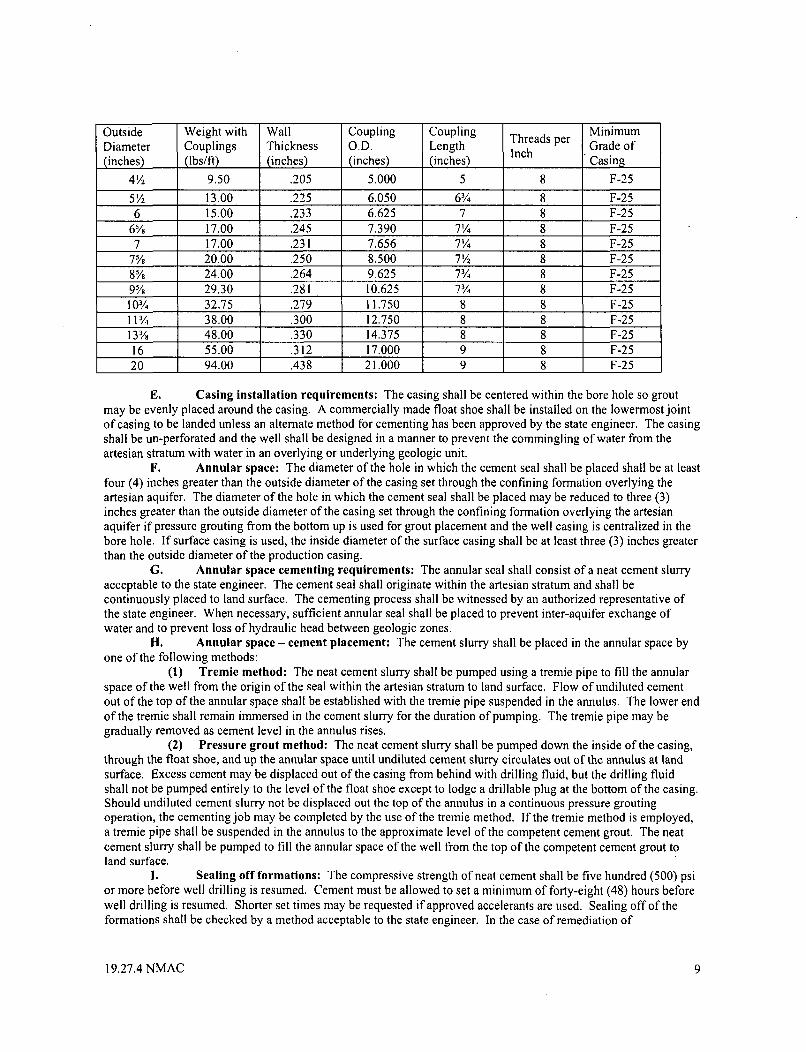
MinimumOutside Weight with Wall Coupling Coupling Threads per Grade ofDiameter Couplings Thickness O.D. Length Inch(inches) (lbs/fl) (inches) (inches) Casing
4V2 9.50 .205 5.000 5 8 F-25
51/2 13.00 .225 6.050 6/ 8 F-256 15.00 .233 6.625 7 8 F-25
6% 17.00 .245 7.390 7¼/4 8 F-257 17.00 .231 7.656 7¼/4 8 F-25
7% 20.00 .250 8.500 7'? 8 F-258% 24.00 .264 9.625 7¾/4 8 F-259% 29.30 .281 10.625 7¾/4 8 F-2510%/4 32.75 .279 11.750 8 8 F-25113 /4 38.00 .300 12.750 8 8 F-2513% 48.00 .330 14.375 8 8 F-25
16 55.00 .312 17.000 9 8 F-2520 94.00 .438 21.000 9 8 F-25
E. Casing installation requirements: The casing shall be centered within the bore hole so groutmay be evenly placed around the casing. A commercially made float shoe shall be installed on the lowermost jointof casing to be landed unless an alternate method for cementing has been approved by the state engineer. The casingshall be un-perforated and the well shall be designed in a manner to prevent the commingling of water from theartesian stratum with water in an overlying or underlying geologic unit.
F. Annular space: The diameter of the hole in which the cement seal shall be placed shall be at leastfour (4) inches greater than the outside diameter of the casing set through the confining formation overlying theartesian aquifer. The diameter of the hole in which the cement seal shall be placed may be reduced to three (3)inches greater than the outside diameter of the casing set through the confining formation overlying the artesianaquifer if pressure grouting from the bottom up is used for grout placement and the well casing is centralized in thebore hole, If surface casing is used, the inside diameter of the surface casing shall be at least three (3) inches greaterthan the outside diameter of the production casing.
G. Annular space cementing requirements: The annular seal shall consist of a neat cement slurryacceptable to the state engineer. The cement seal shall originate within the artesian stratum and shall becontinuously placed to land surface. The cementing process shall be witnessed by an authorized representative ofthe state engineer. When necessary, sufficient annular seal shall be placed to prevent inter-aquifer exchange ofwater and to prevent loss of hydraulic head between geologic zones.
H. Annular space - cement placement: The cement slurry shall be placed in the annular space byone of the following methods:
(1) Tremie method: The neat cement slurry shall be pumped using a tremie pipe to fill the annularspace of the well from the origin of the seal within the artesian stratum to land surface. Flow of undiluted cementout of the top of the annular space shall be established with the tremie pipe suspended in the annulus. The lower endof the tremie shall remain immersed in the cement slurry for the duration of pumping. The tremie pipe may begradually removed as cement level in the annulus rises.
(2) Pressure grout method: The neat cement slurry shall be pumped down the inside of the casing,through the float shoe, and up the annular space until undiluted cement slurry circulates out of the annulus at landsurface. Excess cement may be displaced out of the casing from behind with drilling fluid, but the drilling fluidshall not be pumped entirely to the level of the float shoe except to lodge a drillable plug at the bottom of the casing.Should undiluted cement slurry not be displaced out the top of the annulus in a continuous pressure groutingoperation, the cementing job may be completed by the use of the tremie method. If the tremie method is employed,a tremie pipe shall be suspended in the annulus to the approximate level of the competent cement grout. The neatcement slurry shall be pumped to fill the annular space of the well from the top of the competent cement grout toland surface.
I. Sealing off formations: The compressive strength of neat cement shall be five hundred (500) psior more before well drilling is resumed. Cement must be allowed to set a minimum of forty-eight (48) hours beforewell drilling is resumed. Shorter set times may be requested if approved accelerants are used. Sealing off of theformations shall be checked by a method acceptable to the state engineer. In the case of remediation of
19.27.4 NMAC 9
unanticipated artesian bore holes, the compressive strength of neat cement shall be one thousand (1,000) psi or morebefore artesian head is shut-in at the wellhead.
J. Repair requirements: When an artesian well is in need of repair, the permittee or owner of theland upon which the well is located shall provide a plan of operations to the state engineer. The plan of operationsshall be prepared in accordance with Subsection A of 19.27.4.31 NMAC. Before repairs are made to an artesianwell, the well shall first be inspected by an authorized representative of the state engineer to determine if thecondition of the well is such that it may be repaired. When a leak in the casing is found and the casing and well areotherwise in good condition, the state engineer may allow the well to be repaired. A packer or bridge plug may berequired to complete necessary well repairs. The use of a lead packer is prohibited. An inspection shall be made atthe completion of the work to determine if the repair is satisfactory. During an inspection, the well shall be open toallow for the entrance of equipment for testing and inspection.
K. Plugging requirements: An artesian well that is abandoned or not properly constructed shall beimmediately plugged. Plugging of an artesian well shall require submittal of a plan of operations in accordance withSubsection A of 19.27.4.31 NMAC. The well shall be plugged from the bottom upwards with a neat cement slurry.The well plugging shall be witnessed by an authorized representative of the state engineer.
(1) Well plugging, contamination indicated: Wells encountering contaminated water or soil mayrequire coordination between the office of the state engineer and the New Mexico environment department (or otherauthorized agency or department) prior to the plugging of the well. Specialty plugging materials and pluggingmethods may be required.
(2) Plugging record: A licensed well driller shall keep a record of each well plugged as the workprogresses. A plugging record shall be filed in accordance with Paragraph 3 of Subsection C of 19.27.4.30 NMAC.[19.27.4.31 NMAC - Rp, SE 66-1, Articles 4-15, 4-16, 4-17, 4-18, and 4-19, 8-31-2005]
19.27.4.32 - 19.27.4.35 RESERVED
19.27.4.36 REQUIREMENTS FOR MINE DRILL HOLES THAT ENCOUNTER WATER: Anyperson drilling a mine drill hole that encounters a water bearing stratum shall plug that hole in accordance withSubsection C of 19.27.4.30 NMAC or Subsection K of 19.27.4.31 NMAC within 30 days of encountering the waterbearing stratum.
A. Well record required: Within thirty (30) days after the date of the discovery of water, a wellrecord shall be filed in accordance with Subsection K of 19.27.4.29 NMAC.
B. Artesian water encountered: If artesian water is encountered in the prdcess of drilling a minedrill hole, the drill hole shall be constructed or plugged in accordance with 19.27.4.31 NMAC.[19.27.4.36 NMAC - Rp, SE 66-1, Article 4-21, 8-31-2005]
19.27.4.37 REQUEST FOR VARIANCE: The rules in 19.27.4.29 NMAC, 19.27.4.30 NMAC, and19.27.4.31 NMAC are not intended to cover every situation encountered during well drilling. Geologic conditionsvary across the state, and may warrant the need to deviate from the rules contained in 19.27.4.29 NMAC, 19.27.4.30NMAC, or 19.27.4.31 NMAC. A request for a variance to a rule in 19.27.4 NMAC shall be submitted in writing byan qualified applicant, permit holder, or licensed well driller. It is recommended that a request for variance beprepared by a licensed well driller. The request shall include a detailed justification for the variance and shalldemonstrate that such a variance is necessary to preclude unreasonable hardship or that application of a rule in19.27.4 NMAC would not be practicable. The state engineer may grant the variance if he finds the request to bereasonable and just. The state engineer shall respond in writing to the request for variance and, if the variance ifgranted, the state engineer may impose terms and conditions.[19.27.4.37 NMAC - Rp, SE 66-1, Article 4-22, 8/31/2005]
19.27.4.38 LIBERAL CONSTRUCTION: This part shall be liberally construed to carry out its purpose.[19.27.4.38 NMAC - N, 8/31/2005]
19.27.4.39 SEVERABILITY: If any portion of this part is found to be invalid, the remaining portion of thispart shall remain in force and not be affected.[19.27.4.39 NMAC - N, 8-31-2005]
HISTORY OF 19.27.4 NMAC:
19.27.4 NMAC 10
Pre NMAC History: The material in this part was derived from that previously filed with the State Records Centerand Archives.SE-66-1, Rules and Regulations Governing Drilling of Wells and Appropriation and Use of Ground Water in NewMexico, Article 4, Well Drillers Licensing, Construction, Repair and Plugging Of Wells, originally filed with theSupreme Court Law Library I 1/1/66. Filed with the State Records Center 6/27/91.
History of Repealed Material:SE-66-1, Rules and Regulations Governing Drilling of Wells and Appropriation and Use of Ground Water in NewMexico, Article 4, Well Drillers Licensing, Construction, Repair and Plugging of Wells - Repealed 8/31/2005.
19.27.4 NMAC I I
APPENDIX CNMED Monitoring Well Construction Requirements
(Attachment 19)
New Mexico Environment Department NASA WSTFNovember 2009 Permit No. NM8800019434
ATTACHMENT 19
MONITORING WELL CONSTRUCTION REQUIREMENTS
19.1 TYPES OF MONITORING WELLS
Two types of groundwater monitoring wells are required at the Facility: single completion(containing one screened interval) and multiple screened wells. General drilling procedures arepresented in Section 19.2 and monitoring well construction requirements are presented in Section19.3 of this Permit Attachment.
19.2 DRILLING METHODS
Groundwater monitoring wells and piezometers must be designed and constructed in a manner thatwill yield high quality samples, ensure that the well will last the duration of the project, and ensurethat the well will not serve as a conduit for contaminants to migrate between different stratigraphicunits or aquifers. The design and construction of groundwater monitoring wells shall comply withthe guidelines established in various EPA RCRA guidance, including, but not limited to:
" U.S. EPA, RCPRA Groundwater Monitoring. Draft Technical Guidance, EPA/530-R-93-001, November, 1992;
" U.S. EPA, RCRA Groundwater Monitoring Technical Enforcement GuidanceDocument, OSWER-9950. 1, September, 1986; and
* Aller, L., Bennett, T.W., Hackett, G., Petty, R.J., Lehr, J.H., Sedoris, H., Nielsen, D.M.,and Denne, J.E., Handbook of Suggested Practices for the Design and Installation ofGroundwater Monitoring Wells, EPA 600/4-89/034, 1989.
A variety of methods are available for drilling monitoring wells. While the selection of the drillingprocedure is usually based on the site-specific geologic conditions, the following issues shall also beconsidered:
* Drilling shall be performed in a manner that minimizes impacts to the natural propertiesof the subsurface materials.
* Contamination and cross-contamination of groundwater and aquifer materials during
drilling shall be avoided.
" The drilling method shall allow for the collection of representative samples of rock,unconsolidated materials, and soil.
* The drilling method shall allow the Permittee to determine when the appropriate
location for the screened interval(s) has been encountered.
* The drilling method shall allow for the proper placement of the filter pack and annularsealants. The borehole diameter shall be at least four inches larger in diameter than thenominal diameter of the well casing and screen to allow adequate space for placement ofthe filter pack and annular sealants.
The drilling method shall allow for the collection of representative groundwater samples. Drillingfluids (which includes air) shall be used only when minimal impact to the surrounding formation andgroundwater can be ensured.
58
New Mexico Environment Department NASA WSTFNovember 2009 Permit No. NM8800019434
A brief description of the different drilling methods that may be appropriate for the construction ofmonitoring wells at the Facility follows. Many of these methods may be used alone, or incombination, to install monitoring wells at the Facility. While the selection of the specific drilling
*procedure will usually depend on the site-specific geologic conditions, justification for the methodselected must be provided to NMED.
19.2.1 Hollow-Stem Auger
The hollow-stem continuous flight auger consists of a hollow, steel shaft with a continuous, spiraledsteel flight welded onto the exterior site of the stem. The stem is connected to an auger bit and,when rotated, transports cuttings to the surface. The hollow stem of the auger allows drill rods, split-spoon core barrels, Shelby tubes, and other samplers to be inserted through the center of the auger sothat samples may be retrieved during the drilling operations. The hollow stem also acts totemporarily case the borehole, so that the well screen and casing (riser) may be inserted downthrough the center of the augers once the desired depth is reached, minimizing the risk of possiblecollapse of the borehole. A bottom plug or pilot bit can be fastened onto the bottom of the augers tokeep out most of the soils and/or water that have a tendency to clog the bottom of the augers duringdrilling. Drilling without a center plug is acceptable provided that the soil plug, formed in thebottom of the auger, is removed before sampling or installing well casings. The soil plug can beremoved by washing out the plug using a side discharge rotary bit, or augering out the plug with asolid-stem auger bit sized to fit inside the hollow-stem auger. In situations where heaving sands area problem, potable water may be poured into the augers to equalize the pressure so that the inflow offormation materials and water shall be held to a minimum when the bottom plug is removed. Thehollow-stem auger method is best suited for drilling shallow overburden wells.
19.2.2 Air Rotary/Air Down-The-Hole Hammer/ODEX
The air rotary method consists of a drill pipe or drill stem coupled to a drill bit that rotates and cutsthrough soils and rock. The cuttings produced from the rotation of the drilling bit are transported tothe surface by compressed air, which is forced down the borehole through the drill pipe and returnsto the surface through the annular space (between the drill pipe and the borehole wall). Thecirculation of the compressed air not only removes the cuttings from the borehole but also helps tocool the drill bit. The use of air rotary drilling is best suited for hard-rock formations. In softunconsolidated formations, casing is driven to keep the formation from caving. When using airrotary, the air compressor shall have an in-line filter system to filter the air coming from thecompressor. The filter system shall be inspected regularly to insure that the system is functioningproperly. In addition, a cyclone velocity dissipator or similar air containment/dust-suppressionsystem shall be used to funnel the cuttings to one location instead of allowing the cuttings todischarge uncontrolled from the borehole. Air rotary that employs the dual-tube (reverse circulation)drilling system is acceptable because the cuttings are contained within the drill stem and aredischarged through a cyclone velocity dissipator to the ground surface.
The injection of air into the borehole during air rotary drilling has the potential to alter the naturalproperties of the subsurface. This can occur through air-stripping of the VOCs in both soil andgroundwater in the vicinity of the borehole, altering the groundwater geochemical parameters (e.g.,pH and redox potential), and potentially increasing biodegradation of organic compounds in theaquifer near the borehole. These factors may prevent the well from yielding groundwater samplesthat are representative of in-situ conditions.
59
New Mexico Environment Department NASA WSTFNovember 2009 Permit No. NM8800019434
In hard, abrasive, consolidated rock, a down-the-hole hammer may be more appropriate than the airrotary method. In this method, compressed air is used to actuate and operate a pneumatic hammer aswell as lift the cuttings to the surface and cool the hammer bit. One drawback of the down-the-holehammer is that oil is required in the air stream to lubricate the hammer-actuating device, and this oilcould potentially contaminate the soil in the vicinity of the borehole and the aquifer.
The ODEX method is a variation of the air rotary method in which a casing-driving technique isused in combination with air rotary drilling. With the ODEX system, the drill bit extends outwardand reams a pilot hole large enough for a casing assembly to slide down behind the drill bitassembly. As a result, casing is advanced simultaneously while drilling the hole.
19.2.3 Water Rotary and Mud Rotary
The water and mud rotary drilling methods consist of rotary drilling techniques where water ordrilling mud is used as the circulating fluid. In both methods, the circulating fluid is pumped downthrough the drill pipe and is returned back up the borehole through the annular space. Thecirculating fluid stabilizes the borehole, cools the drill bit, and carries the drill cuttings up to thesurface. While the water and mud rotary drilling techniques are rapid and effective drilling methods,the recognition of water-bearing zones is hampered by the addition of water into the system.
Mud rotary drilling is similar to water rotary drilling with the exception that mud additives are addedto the water to change the properties (e.g., density, viscosity, yield point, gel strength, fluid-loss-control effectiveness, lubricity) of the circulating fluid. Drilling muds provide greater boreholestabilization than water alone. There are several types of mud presently available, includingbentonite, barium sulfate, organic polymers, cellulose polymers, and polyacrylamides. Whiledrilling muds enhance the stability of the borehole and allow for drilling in formations notappropriate to other methods, they can adversely affect the hydrologic properties and geochemistryof the aquifer. For example, drilling fluid invasion and the buildup of borehole filter cake mayreduce the effective porosity of the aquifer in the vicinity of the borehole. In addition, bentonitedrilling muds may affect the pH of groundwater and organic polymer drilling muds have beenobserved to facilitate bacterial growth, which reduces the reliability of sampling results. If polymeremulsions are to be used in the drilling program at the Facility, polymer dispersion agents shall beused at the completion of the drilling program to remove the polymers from the boreholes. Forexample, if EZ Mud® is used as a drilling additive, a dispersant (e.g., BARAFOS® or five percentsodium hypochlorite) shall be used to disperse and chemically breakdown the polymer prior todeveloping and sampling the well.
19.2.4 Dual-Wall Reverse Circulation
The dual-wall reverse circulation drilling method utilizes a double-wall drill pipe and has the reversecirculation of other conventional rotary drilling methods. The circulating fluid (water or air) ispumped down the borehole between the outer and inner drill pipe, and returns up the inner drill pipe.Cuttings are lifted to the surface through the inner drill pipe. The inner drill pipe rotates the bit, andthe outer drill pipe acts as a casing and stabilizes the borehole. Typically, a tri-cone bit is used whendrilling through unconsolidated formations and a down-the-hole hammer is used in hard rock.
The dual-wall reverse circulation rotary method is one of the better methods available for obtainingrepresentative and continuous formation samples while drilling. If a roller cone bit is used, theformation that is being drilled is located only a few inches ahead of the double-wall pipe. As a
60
New Mexico Environment Department NASA WSTFNovember 2009 Permit No. NM8800019434
result, the cuttings observed at the surface represent no more than one foot of the formation at anypoint in time.
When drilling with air, an in-line filter shall be used to remove oil or other impurities from theairstream. However, if a down-the-hole hammer is used, it must be used with caution since itrequires oil in the airstream to lubricate the hammer. This could possibly introduce contaminants tothe borehole and aquifer.
19.2.5 Resonant Sonic
Resonant sonic drilling is a method that uses a sonic drill head to produce high-frequency, high-forcevibrations in a steel drill pipe. The vibrations in the pipe create a cutting action at the bit face, whichallows a continuous core of the formation to move into a core barrel. The method requires nodrilling fluid, drills very fast (up to one ft/sec in certain formations), drills at any angle through allformations (rock, clay, sand, boulders, permafrost, glacial till), and yields virtually no cuttings in thedrilling process. While there are numerous advantages to this process, the primary disadvantage isthe cost of the method. This drilling method has been proven and used at various facilities.
19.2.6 Cryogenic
Cryogenic drilling is a technique that uses standard air rotary drilling methods, but employs coldnitrogen gas as the circulating fluid instead of compressed air. The use of nitrogen gas as thecirculation fluid freezes the borehole wall while drilling, which stabilizes unconsolidated sedimentsand prevents potential cross-contamination of different water-bearing zones. In addition, the methodproduces fewer cuttings than liquid based drilling methods, requires minimal equipmentmodifications to existing drill rigs, and does not add contaminants to the borehole during the drillingprocess due to the benign nature of nitrogen gas. The method is especially applicable for drillingthrough alternating hard (competent) and soft (unconsolidated) formations. This drilling method hasbeen tested by the Department of Energy (DOE) and proposed for future use at various DOEfacilities.
19.3 WELL CONSTRUCTION/COMPLETION METHODS
19.3.1 Well Construction Materials
Well construction materials shall be selected based on the goals and objectives of the proposedmonitoring program and the geologic conditions at the site. When selecting well constructionmaterials, the primary concern shall be selecting materials that will not contribute foreignconstituents or remove contaminants from the groundwater. Other factors to be considered includethe tensile strength, compressive strength, and collapse strength of the materials; length of time themonitoring well will be in service; and the material's resistance to chemical and microbiologicalcorrosion. Generally, if the monitoring program requires the analysis of organic constituents,stainless steel or fluoropolymer materials should be used. However, if the monitoring programrequires only inorganic constituent analyses, polyvinyl chloride (PVC) materials may be used. PVCshould not be used for monitoring wells where organic constituents will be analyzed due to itspotential for sorption and leaching of contaminants.
Well screen and casing materials acceptable for the construction of RCRA monitoring wells includestainless steel (304 or 316), rigid PVC (meeting American National Standards Institute/NationalSanitation Foundation Standard 14), and fluoropolymer materials (polytetrafluoroethylene,
61
New Mexico Environment Department NASA WSTFNovember 2009 Permit No. NM8800019434
fluorinated ethylene propylene, and polyvinylidene). In addition, there are other materials availablefor the construction of monitoring wells including acrylonitrile butadiene styrene (ABS), fiberglass-reinforced plastic (FRP), black iron, carbon steel, and galvanized steel, but these materials are notrecommended for use in long term monitoring wells due to their low resistance to chemical attackand potential contribution of contamination to the groundwater. However, these materials may beused in the construction of monitoring wells where they will not be in contact with the groundwaterthat will be sampled (e.g., carbon steel pipe used as surface casing).
19.3.2 Well Construction Techniques
19.3.2.a Single-cased Wells
The borehole shall be bored, drilled, or augered as close to vertical as possible, and checked with aplumb bob, level, or appropriate downhole logging tool. Slanted boreholes shall not be acceptableunless specified in the design. The borehole shall be of sufficient diameter so that well constructioncan proceed without major difficulties. To assure an adequate size, a minimum two-inch annularspace is required between the casing and the borehole wall (or the hollow-stem auger wall). Thetwo-inch annular space around the casing will allow the filter pack, bentonite seal, and annular groutto be placed at an acceptable thickness. Also, the two-inch annular space will allow up to a 1.5-inchouter diameter tremie pipe to be used for placing the filter pack, bentonite seal, and grout at thespecified intervals.
It may be necessary to overdrill the borehole so that any soils that have not been removed (or thathave fallen into the borehole during augering or drill stem retrieval) will fall to the bottom of theborehole below the depth where the filter pack and well screen are to be placed. Normally, three tofive ft is sufficient for overdrilling shallow wells. Deep wells may require deeper overdrilling. Theborehole can also be overdrilled to allow for an extra space for a well sump to be installed. If theborehole is overdrilled deeper than desired, it can be backfilled to the designated depth withbentonite pellets or the filter pack.
The well casings (riser assembly) should be secured to the well screen by flush-jointed threads orother appropriate connections and placed into the borehole and plumbed by the use of centralizers, aplumb bob, or a level. No petroleum-based lubricating oils or grease shall be used on casing threads.Teflon tape can be used to wrap the threads to insure a tight fit and minimize leakage. No glue ofany type shall be used to secure casing joints. Teflon or fluoropolymer elastomer "O" rings can alsobe used to ensure a tight fit and minimize leakage. "0" rings made of materials other than Teflon orfluoropolymer elastomers are not acceptable if the well will be sampled for organic compoundanalyses. Before the well screen and casings are placed at the bottom of the borehole, at least sixinches of filter material shall be placed at the bottom to serve as a firm footing. The string of wellscreen and casing should then be placed into the borehole and plumbed. If centralizers are used, theyshall be placed below the well screens and above the bentonite annular seals so that the placement ofthe filter pack, overlying bentonite seal, and annular grout will not be hindered. Centralizers placedin the wrong locations can cause bridging during material placement. If installing the well screenand casings through hollow-stem augers, the augers shall be slowly extracted as the filter pack,bentonite seal, and grout are tremied or poured into place. The gradual extraction of the augers willallow the materials being placed in the augers to flow out of the bottom of the augers into theborehole. If the augers are not gradually extracted, the materials will accumulate at the bottom of theaugers causing potential bridging problems. After the string of well screen and casing is plumb, the
62
New Mexico Environment Department NASA WSTFNovember 2009 Permit No. NM8800019434
filter material shall be placed around the well screen (preferably by the tremie pipe method) up to thedesignated depth. After the filter pack has been installed, the bentonite seal shall be placed directlyon top of the filter pack up to the designated depth or a minimum of two ft above the filter pack,whichever is greater. After the bentonite seal has hydrated for the specified time, the annular groutshall be pumped by the tremie method into the annular space around the casings (riser assembly) upto within two ft of the ground surface or below the frost line, whichever is greater. The grout shallbe allowed to cure for a minimum of 24 hours before the surface pad and protective casing areinstalled. After the surface pad and protective casing are installed, bumper guards (guideposts) shallbe installed (if necessary).
19.3.2.b Double-cased Wells
Double-cased wells should be constructed when there is reason to believe that interconnection of twoaquifers by well construction may cause cross contamination, or when flowing sands make itimpossible to install a monitoring well using conventional methods. A pilot borehole should beadvanced through the overburden and the contaminated zone into a clay, confining layer, or bedrock.An outer casing (surface or pilot casing) shall be placed into the borehole and sealed with grout. Theborehole and outer casing should extend into tight clay a minimum of two ft or into competentbedrock a minimum of one foot. The total depth into the clay or bedrock will vary depending uponthe plasticity of the clay and the extent of weathering and fracturing of the bedrock. The size of theouter casing shall be of sufficient inside diameter to contain the inner casing and the two-inchannular space. In addition, the borehole shall be of sufficient size to contain the outer casing and thetwo-inch minimum outer annular space, if applicable.
The outer casing shall be grouted by the tremie method from the bottom of the borehole to withintwo ft of the ground surface. The grout shall be pumped into the annular space between the outercasing and the borehole wall. This can be accomplished by either placing the tremie pipe in theannular space and pumping the grout from the bottom of the borehole to the surface, or placing agrout shoe or plug inside the casing at the bottom of the borehole and pumping the grout through thebottom grout plug and up the annular space on the outside of the casing. The grout shall consist of aType I Portland cement and bentonite or other approved grout to provide a rigid seal. A minimum of24 hours shall be allowed for the grout plug (seal) to cure before attempting to drill through it.When drilling through the seal, care shall be taken to avoid cracking, shattering, and washing out ofthe seal. If caving conditions exist so that the outer casing cannot be sufficiently sealed by grouting,the outer casing shall be driven into place and a grout seal placed in the bottom of the casing.
19.3.2.c Bedrock Wells
The installation of monitoring wells into bedrock can be accomplished in two ways. The firstmethod is to drill or bore a pilot borehole through the soil overburden into the bedrock. An outercasing is installed into the borehole by setting it into the bedrock, and grouting it into place. Afterthe grout has set, the borehole can be advanced through the grout seal into the bedrock. Thepreferred method of advancing the borehole into the bedrock is rock coring. Rock coring makes asmooth, round hole through the seal and into the bedrock without cracking or shattering the seal.Roller cone bits are used in soft bedrock, but extreme caution should be taken when using a rollercone bit to advance through the grout seal in the bottom of the borehole because excessive water andbit pressure can cause cracking, eroding (washing), and/or shattering of the seal. Low volume airhammers may be used to advance the borehole, but they have a tendency to shatter the seal because
63
New Mexico Environment Department NASA WSTFNovember 2009 Permit No. NM8800019434
of the hammering action. If the structural integrity of the grout seal is in question, a pressure test canbe utilized to check for leaks. If the seal leaks, the seal is not acceptable. When the drilling iscomplete, the finished well will consist of an open borehole from the ground surface to the bottom ofthe well. The major limitation of open borehole bedrock wells is that the entire bedrock intervalserves as the monitoring zone.
The second method is to install the outer surface casing and drill the borehole into bedrock, and theninstall an inner casing and well screen with the filter pack, bentonite seal, and annular grout. Thewell is completed with a surface protective casing and concrete pad. This well installation methodgives the flexibility of isolating the monitoring zone(s) and minimizing inter-aquifer flow. Inaddition, it gives structural integrity to the well, especially in unstable areas (e.g., steeply dippingshales) where the bedrock has a tendency to shift or move when disturbed.
19.3.3 Well Screen and Filter Pack Design
Well screens and filter packs shall be designed to accurately sample the aquifer zone that the well isintended to sample, minimize the passage of formation materials (turbidity) into the well, and ensuresufficient structural integrity to prevent the collapse of the intake structure. The selection of the wellscreen length depends upon the objective of the well. Piezometers and wells where only a discreteflow path is monitored are generally completed with short screens (two ft or less). While monitoringwells are usually constructed with longer screens (usually five to ten ft), they shall be kept to theminimum length appropriate for intercepting a contaminant plume. The screen slot size shall beselected to retain from 90 to 100 percent of the filter pack material in artificially filter packed wells,and from 50 to 100 percent of the formation material in naturally packed wells. All well screensshall be factory wire-wrapped or machine slotted.
A filter pack shall be used when: 1) the natural formation is poorly sorted; 2) a long screen interval isrequired or the screen spans highly stratified geologic materials of widely varying grain sizes; 3) thenatural formation is uniform fine sand, silt, or clay, 4) the natural formation is thin-bedded; 5) thenatural formation is poorly cemented sandstone; 6) the natural formation is highly fractured orcharacterized by relatively large solution channels; 7) the natural formation is shale or coal that willact as a constant source of turbidity to groundwater samples; or 8) the diameter of the borehole issignificantly greater than the diameter of the screen. The use of natural formation material as a filterpack is only recommended when the natural formation materials are relatively coarse-grained,permeable, and uniform in grain size.
Filter pack materials shall consist of clean, rounded to well-rounded, hard, insoluble particles ofsiliceous composition (industrial grade quartz sand or glass beads). The required grain-sizedistribution or particle sizes of the filter pack materials shall be selected based upon a sieve analysisof the aquifer materials or the formation to be monitored, or the characteristics of the aquifermaterials using information acquired during previous investigations.
Where sieve analyses are used to select the appropriate filter pack particle size, the results of a sieveanalysis of the formation materials are plotted on a grain-size distribution graph, and a grain-sizedistribution curve is generated. The 70 percent retained grain size value should be multiplied by afactor between four and six (four for fine, uniform formations and six for coarse, non-uniformformations). A second grain-size distribution curve is then drawn on the graph for this new value,ensuring that the uniformity coefficient does not exceed 2.5. The filter pack that shall be used willfall within the area defined by these two curves.
64
New Mexico Environment Department NASA WSTFNovember 2009 Permit No. NM8800019434
Once the filter pack size is determined, the screen slot size shall be selected to retain at least 90percent of the filter pack material. The Permittee may propose the use of a pre-determined wellscreen slot size and filter pack for monitoring wells in the site-specific work plans submitted toNMED.
The filter pack shall be installed in a manner that prevents bridging and particle-size segregation.Filter packs placed below the water table shall be installed by the tremie pipe method. Filter packmaterials shall not be poured into the annular space unless the well is shallow (e.g., less than 30 ftdeep) and the filter pack material can be poured continuously into the well without stopping. Atleast two inches of filter pack material shall be installed between the well screen and the boreholewall, and two ft of material shall extend above the top of the well screen. A minimum of six-inchesof filter pack material shall also be placed under the bottom of the well screen to provide a firmfooting and an unrestricted flow under the screened area. In deep wells (e.g., greater than 200 ftdeep), the filter pack may not compress when initially installed. As a result, filter packs may need tobe installed as high as five ft above the screened interval in these situations. The precise volume offilter pack material required shall be calculated and recorded before placement, and the actualvolume used shall be determined and recorded during well construction. Any significantdiscrepancy between the calculated and actual volume shall be explained. Prior to installing thefilter pack annular seal, a one to two-ft layer of chemically inert fine sand shall be placed over thefilter pack to prevent the intrusion of annular sealants into the filter pack.
Several pre-fabricated groundwater sampling systems that can be installed in open boreholes areavailable on the market. These include multi-level borehole completion systems (e.g., Westbay MPSystem®) and pneumatically deployed inverting PVC membranes (e.g., SEAMIST). If these typesof borehole completions are to be used in the Facility wells, they shall be installed under thesupervision of personnel from the authorized vendor unless otherwise approved by NMED.
19.3.4 Annular Sealant
The annular space between the well casing and the borehole must be properly sealed to preventcross-contamination of samples and the groundwater. The materials used for annular sealants shallbe chemically inert with respect to the highest anticipated concentration of chemical constituentsexpected in the groundwater at the Facility. In general, the permeability of the sealing material shallbe one to two orders of magnitude lower than the least permeable parts of the formation in contactwith the well. The precise volume of annular sealants required shall be calculated and recordedbefore placement, and the actual volume shall be determined and recorded during well construction.Any significant discrepancy between the calculated volume and the actual volume shall beexplained.
During well construction, an annular seal shall be placed on top of the filter pack. This seal shallconsist of a high solids (10-30 percent) bentonite material in the form of bentonite pellets, granularbentonite, or bentonite chips. The bentonite seal shall be placed in the annulus through a tremie pipeif the well is deep (greater than 30 ft), or by pouring directly down the annulus in shallow wells (lessthan 30 ft). If the bentonite materials are poured directly down the annulus (which is an acceptablemethod only in wells less than 30 feet deep), a tamping device shall be used to ensure that the seal isemplaced at the proper depth and the bentonite has not bridged higher in the well casing. Thebentonite seal shall be placed above the filter pack a minimum of two ft vertical thickness. Thebentonite seal shall be allowed to completely hydrate in conformance with the manufacturer'sspecifications prior to installing the overlying annular grout seal. The time required for the bentonite
65
New Mexico Environment Department NASA WSTFNovember 2009 Permit No. NM8800019434
seal to completely hydrate will differ with the materials used and the specific conditionsencountered, but is generally a minimum of four to 24 hours.
A grout seal shall be installed on top of the filter pack annular seal. The grout seal may consist of ahigh solids (30 percent) bentonite grout, a neat cement grout, or a cement/bentonite grout. The groutshall be pumped under pressure (not gravity fed) into the annular space by the tremie pipe method,from the top of the filter pack annular seal to within a few ft of the ground surface. The tremie pipeshall be equipped with a side discharge port (or bottom discharge for grouting at depths greater than100 feet) to minimize damage to the filter pack or filter pack annular bentonite seal during groutplacement. The grout seal shall be allowed to cure for a minimum of 24 hours before the concretesurface pad is installed. All grouts shall be prepared in accordance with the manufacturer'sspecifications. High solids (30 percent) bentonite grouts shall have a minimum density of tenpounds per gallon (as measured by a mud balance) to ensure proper setup. Cement grouts shall bemixed using six and one-half to seven gallons of water per 94-pound bag of Type I Portand cement.Bentonite (five to ten percent) may be added to delay the setting time and reduce the shrinkage of thegrout.
19.3.5 Well Development
All monitoring wells shall be developed to create an effective filter pack around the well screen,correct damage to the formation caused by drilling, remove fine particles from the formation near theborehole, and assist in restoring the natural water quality of the aquifer in the vicinity of the well.Development stresses the formation around the screen, as well as the filter pack, so that mobile fines,silts, and clays are pulled into the well and removed. Development is also used to remove anyforeign materials (e.g., water, drilling mud) that may have been introduced into the borehole duringthe drilling and well installation activities, and to aid in the equilibration that will occur between thefilter pack, well casing, and the formation water. The development of a well is extremely importantto ensuring the collection of representative groundwater samples.
Newly installed monitoring wells shall not be developed for at least 48 hours after the outerprotective casing is installed. This will allow sufficient time for the well materials to cure before thedevelopment procedures are initiated. A new monitoring well shall be developed until the column ofwater in the well is free of visible sediment, and the pH, temperature, turbidity, and specificconductivity have stabilized. In most cases, the above requirements can be satisfied. However, insome cases, the pH, temperature, and specific conductivity may stabilize but the water remainsturbid. In this case, the well may still contain well construction materials, such as drilling mud in theform of a mud cake or formation soils that have not been washed out of the borehole. Thick drillingmud cannot be flushed out of a borehole with one or two well volumes of flushing. Instead,continuous flushing over a period of several days may be necessary to complete the welldevelopment. If the well is pumped dry, the water level shall be allowed to sufficiently recoverbefore the next development period is initiated. The common methods used for developing wellsinclude:
* Pumping and overpumping;
* Backwashing;
* Surging (with a surge block);
Bailing;
66
New Mexico Environment Department NASA WSTFNovember 2009 Permit No. NM8800019434
* Jetting; and
* Airlift pumping.
These development procedures can be used, either individually or in combination, to achieve themost effective well development. However, the most favorable well development methods includepumping, overpumping, bailing, surging, or a combination of these methods. Well developmentmethods and equipment that alter the chemical composition of the groundwater shall not be used.Development methods that involve adding water or other fluids to the well or borehole, or that useair to accomplish well development should be avoided, if possible. Approval shall be obtained fromNMED prior to introducing air, water, or other fluids into the well for the purpose of welldevelopment. If water is introduced to a borehole during well drilling and completion, then the sameor greater volume of water shall be removed from the well during development. In addition, thevolume of water withdrawn from a well during development shall be recorded.
19.3.6 Surface Completion
Monitoring wells may be completed either as flush-mounted wells, or as above-ground completions.A surface seal shall be installed over the grout seal and extended vertically up the well annulus to theland surface. The lower end of the surface seal shall extend a minimum of one foot below the frostline to prevent damage from frost heaving. The composition of the surface seal shall be neat cementor concrete. In above-ground completions, a minimum three-feet wide, four-inch thick concretesurface pad shall be installed around the well at the same time the protective casing is installed. Thesurface pad shall be sloped so that drainage will flow away from the protective casing and off thepad. In addition, a minimum of one inch of the finished pad shall be below grade or groundelevation to prevent washing and undermining by soil erosion.
A locking protective casing shall be installed around the well casing (riser) to prevent damage orunauthorized entry. The protective, casing shall be anchored in the concrete surface pad below thefrost line and extend several inches above the well riser stickup. A weep hole shall be drilled intothe protective casing just above the top of the concrete surface pad to prevent water fromaccumulating and freezing inside the protective casing around the well riser. A cap shall be placedon the well riser to prevent tampering or the entry of foreign materials, and a lock shall be installedon the protective casing to provide security. If the wells are located in an area that receives traffic, aminimum of three bumper guards consisting of steel pipes three to four inches in diameter and aminimum of five-feet length should be installed. The bumper guards should be installed to aminimum depth of two feet below the ground surface in a concrete footing and extend a minimum ofthree feet above ground surface. The pipes should be filled with concrete to provide additionalstrength. The pipes should be painted a bright color to reduce the possibility of vehicular damage.
If flush-mounted completions are required (e.g., in active roadway areas), a protective structure suchas a utility vault or meter box should be installed around the well casing. In addition, measuresshould be taken to prevent the accumulation of surface water in the protective structure and aroundthe well intake. These measures should include outfitting the protective structure with a steel lid ormanhole cover that has a rubber seal or gasket, and ensuring that the bond between the cementsurface seal and the protective structure is watertight.
67
New Mexico Environment Department NASA WSTFNovember 2009 Permit No. NM8800019434
19.4 WELL ABANDONMENT
All well abandonment must be conducted in accordance with 19.27.4 NMAC including submittal ofa plan for well abandonment in accordance with 19.27.4.30 C NMAC. Wells are usually abandonedwhen they are no longer required in the monitoring network or when they are damaged beyondrepair. The goal of well abandonment is to seal the borehole in such a manner that the well cannotact as a conduit for migration of contaminants from the ground surface to the aquifer or betweenaquifers. To properly abandon a well, the preferred method is to completely remove the well casingand screen from the borehole, clean out the borehole, and backfill with a cement or bentonite grout,neat cement, or concrete. The well abandonment procedure must also comply with current EPA wellabandonment guidance.
For wells with small diameter casing, abandonment shall be accomplished by overdrilling the wellwith a large diameter hollow-stem auger. After the well has been overdrilled, the well casing andgrout can be lifted out of the ground with a drill rig, and the remaining filter pack can be drilled out.The open borehole can then be pressure grouted (via the tremie pipe method) from the bottom of theborehole to the ground surface. After the grout has cured, the top two ft of the borehole shall befilled with concrete to insure a secure surface seal.
Several other well abandonment procedures are available for wells with larger diameter screens andcasings. One method is to force a drill stem with a tapered wedge assembly or a solid-stem augerinto the well casing and pull the casing out of the ground. However, if the casing breaks or the wellcannot be pulled from the ground, the well will have to be grouted in place. To abandon a well inplace, a tremie pipe shall be placed at the lowest point in the well (at the bottom of the screen or inthe well sump). The entire well is then pressure grouted from the bottom of the well upward. Thepressurized grout will be forced out through the well screen into the filter pack and up the inside ofthe well casing sealing off all breaks and holes in the casing. Once the well is grouted, the casing iscut off even with the ground surface and covered with concrete.
If a PVC well cannot be abandoned due to internal casing damage (e.g., the tremie pipe cannot beextended to the bottom of the screen), it may be necessary to drill out the casing with a roller cone ordrag bit using the wet rotary drilling method, or grind out the casing using a solid-stem augerequipped with a carbide tooth bit. Once the casing is removed, the open borehole can be cleaned outand pressure grouted from the bottom of the borehole upward.
19.5 DOCUMENTATION
All information on the design, construction, and development of each monitoring well shall berecorded and presented on a boring log, a well construction log, and well construction diagram. Thewell construction log and well construction diagram shall include the following information:
* Well name/number;
* Date/time of well construction;
* Borehole diameter and well casing diameter;
* Well depth;
* Casing length;* Casing materials;
68
New Mexico Environment Department NASA WSTFNovember 2009 Permit No. NM8800019434
* Casing and screen joint type;
* Screened interval(s);
* Screen materials;
* Screen slot size and design;
* Filter pack material and size;
* Filter pack volume (calculated and actual);
* Filter pack placement method;
* Filter pack interval(s);
* Annular sealant composition;
* Annular sealant placement method;
* Annular sealant volume (calculated and actual);
* Annular sealant interval(s);
* Surface sealant composition;
* Surface seal placement method;
* Surface sealant volume (calculated and actual);
* Surface sealant interval;
* Surface seal and well apron design and construction;
* Well development procedure and turbidity measurements;
* Well development purge volume(s) and stabilization parameter measurements;
* Type and design and construction of protective casing;
* Well cap and lock;
* Ground surface elevation;
* Survey reference point elevation on well casing;
* Top of monitoring well casing elevation; and
* Top of protective steel casing elevation.
69
APPENDIX DWell Permit Application Form
Example of Completed Well Permit Application FormWell Plugging Plan of Operations Form
Plugging Record Form

File Number:(For OSE Use Only)
NEW MEXICO OFFICE OF THE STATE ENGINEERAPPLICATION FOR PERMIT
TO DRILL AN EXPLORATORY WELL
1. APPLICANT:Name: Work
Contact: HomeAddress:
City: State:
2. LOCATION OF WELL (A, B, C, or D required, E or F if known):
A. 1/4 1/4 1/4 Section: Township:
Phone:Phone:
Zip:
Range: N.M.P.M.in County.
B. X = feet, Y = feet, N.M. Coordinate SystemZone in the Grant.
U.S.G.S. Quad Map
C. Latitude: d m s Longitude: d m s
D. East (m), North (m), UTM Zone 13, NAD (27 or 83)
E. Tract No. , Map No. __ of the Hydrographic Survey
F. Lot No. , Block No. of Unit/Tract of theSubdivision recorded in County.
G. Other:
H. Give State Engineer File Number of existing well:
I. On land owned by (required):
3. WELL INFORMATION:
Approximate depth __ feet; Outside diameter of casing inches.Name of well driller and driller license number
4. ADDITIONAL STATEMENT OR EXPLANATIONS:
Do Not Write Below This Line
Trn Number:File Number:Form: wr-07 page 1 of 2
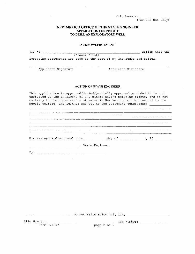
File Number:(For OSE Use Only)
NEW MEXICO OFFICE OF THE STATE ENGINEERAPPLICATION FOR PERMIT
TO DRILL AN EXPLORATORY WELL
ACKNOWLEDGEMENT
(I, We) affirm that the(Please Print)
foregoing statements are true to the best of my knowledge and belief.
Applicant Signature Applicant Signature
ACTION OF STATE ENGINEER
This application is approved/denied/partially approved provided it is notexercised to the detriment of any others having existing rights, and is notcontrary to the conservation of water in New Mexico nor detrimental to thepublic welfare, and further subject to the following conditions:
Witness my hand and seal this day of , 20
State Engineer
By:
Do Not Write Below This Line
File Number:Form: wr-07
Trn Number:page 2 of 2
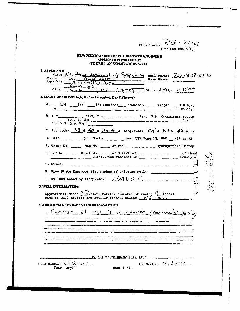
File Number: <,(For OSE Use Only)
NEW MEXICO OFFICE OF THE STATE ENGINEERAPPLICATION FOR PERMT
TO DRILL AN EXPWRATORY WELL
I. AII'LICANrD. PLCName: *&a o TiuvkjbC(JLdl'.. Work Phone: S6~ -05 7Contact: A-. - . . -1 Home Phone:Address: it~
City: I e.E .,6-1 9 a state:/V_ý2zip: S •-t
7. LOCATION OF W!LL (A. B, C, or D reqNrsd,E Dor f N lumm):
A. 1/4 1/4 1/4 Section:in Townshhip:_ Range: N.M.P.M.County,
B. X - feet, Y - feet, N.M. Coordinate SystemZone in the Grant.
U.S.G.S. Quad Map
C. Latitude: 5jd _Jui m ýT Longitude: 105- d 6 _4______S-a
D. East (m), North (m), UTM Zone 13, NAD (27 or 83)
E. Tract No. , Map No. of the Hydrographic Survey
F. Lot No. , Block No. of Unit/Tract of theL=Subdivision recorded in County..--
G. Other:
H. Give State Engineer File Number of existing well: ___
I. On land owned by (required): D/o/ 6 -"
3. WELL INFORMATION:
Approximate depth 3,50feet; Outside diameter of casing inches.Name of well driller and driller license number / -I
4. ADDfITONAL STATEMENT OR EXPLANATIONS:
Do Not Write Below This Line
C-3
T -I
File Number: Zr1' 1/.-0 7 e IForm: wr-07
Tmn Number: t/7. Spage I of 2
El ~
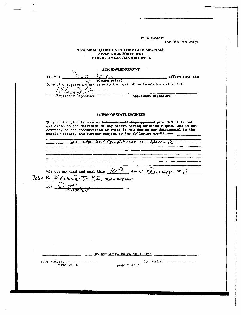
File Number:(For OSE Use Only)
NEW MEXICO OFFICE OF THE STATE ENGINEERAPPLICATION FOR PERMIT
TO DRILL AN EXPLORATORY WELL
ACKNOWLEDGEMENT
(I, We) .}- (A. .*.j.. C J. % ---- affirm ti) (Please Print)
foregoing, tw~ementsare true to the best of my knowledge and belief.
hat the
)4ýi icantýJg~wvtfe- Applicant Signature
ACTION OF STATE ENGINEER
This application is approved/de=pid/pactially appyezve provided it is notexercised to the detriment of any others having existing rights, and is notcontrary to the conservation of water in New Mexico nor detrimental to thepublic welfare, and further subject to the following conditions:
Witness my hand and seal this Iaday of FA tV e. 2 0
7Jo4e T1. EA$ 4 c ~ ~ State Engineer
By:
Do Not Write Below This Line
Elie Number;Form: wr-07
Trn Number:-page 2 of 2
II
WELL PLUGGINGPLAN OF OPERATIONS
NOTE: A Well Plugging Plan of Operations shall be filed with and accepted by the Office of the State Engineer priorto plugging.
I. FILING FEE: There is no filing fee for this form.
II. GENERAL / WELL OWNERSHIP:
Existing Office of the State Engineer POD Number (Well Number) for well to be plugged:
Name of well owner:
Mailing address:
City: State: Zip code:
Phone number: E-mail:
III. WELL DRILLER INFORMATION:
Well Driller contracted to provide plugging services:
New Mexico Well Driller License No.: Expiration Date:
IV. WELL INFORMATION:
Note: A copy of the existing Well Record for the well to be plugged should be attached to this plan.
1) GPS Well Location: Latitude: .deg, min, secLongitude: .deg, min, see, NAD 83
2) Reason(s) for plugging well:
3) Was well used for any type of monitoring program? _ If yes, please use section VII of this form to detail
what hydrogeologic parameters were monitored. If the well was used to monitor contaminated or poor qualitywater, authorization from the New Mexico Environment Department may be required prior to plugging.
4) Does the well tap brackish, saline, or otherwise poor quality water? If yes, provide additional detail,
including analytical results and/or laboratory report(s):
5) Static water level: feet below land surface / feet above land surface (circle one)
6) Depth of the well: feet
Well Plugging PlanVersion: April 30, 2007
Page l of 5
7) Inside diameter of innermost casing: inches.
8) Casing material:
9) The well was constructed with:
___ an open-hole production interval, state the open interval:
___ a well screen or perforated pipe, state the screened interval(s):
10) What annular interval surrounding the artesian casing of this well is cement-grouted?
11) Was the well built with surface casing? If yes, is the annulus surrounding the surface casing grouted
or otherwise sealed? If yes, please describe:
12) Has all pumping equipment and associated piping been removed from the well? If not, describeremaining equipment and intentions to remove prior to plugging in Section VII of this form.
V. DESCRIPTION OF PLANNED WELL PLUGGING:
Note: If this plan proposes to plug an artesian well in a way other than with cement grout, placed bottom to top with a tremiepipe, a detailed diagram of the well showing proposed final plugged configuration shall be attached, as well as any additionaltechnical information, such as geophysical logs, that are necessary to adequately describe the proposal.
I) Describe the method by which cement grout shall be placed in the well, or describe requested plugging methodology
proposed for the well:
2) Will well head be cut-off below land surface after plugging?
VI. PLUGGING AND SEALING MATERIALS:
Note: The plugging of a well that taps poor quality water may require the use of a specialty cement or specialty sealant
1) For plugging intervals that employ cement grout, complete and attach Table A.
2) For plugging intervals that will employ approved non-cement based sealant(s), complete and attach Table B.
3) Theoretical volume of grout required to plug the well to land surface:
4) Type of Cement proposed:
5) Proposed cement grout mix: gallons of water per 94 pound sack of Portland cement.
6) Will the grout be: batch-mixed and delivered to the site
mixed on site
Well Plugging PlanVersion: April 30, 2007
Page 2 of 5
7) Grout additives requested, and percent by dry weight relative to cement:
8) Additional notes and calculations:
VII. ADDITIONAL INFORMATION: List additional information below, or on separate sheet(s):
VIII. SIGNATURE:
I, , say that I have carefully read the foregoing Well Plugging Plan ofOperations and any attachments, which are a part hereof; that I am familiar with the rules and regulations of the StateEngineer pertaining to the plugging of wells and will comply with them, and that each and all of the statements in the WellPlugging Plan of Operations and attachments are true to the best of my knowledge and belief.
Signature of Applicant Date
IX. ACTION OF THE STATE ENGINEER:
This Well Plugging Plan of Operations is:
Approved subject to the attached conditions._ Not approved for the reasons provided on the attached letter.
Witness my hand and official seal this day of ,
John R. D'Antonio, Jr., State Engineer
By:
Well Plugging PlanVersion: April 30, 2007
Page 3 of 5
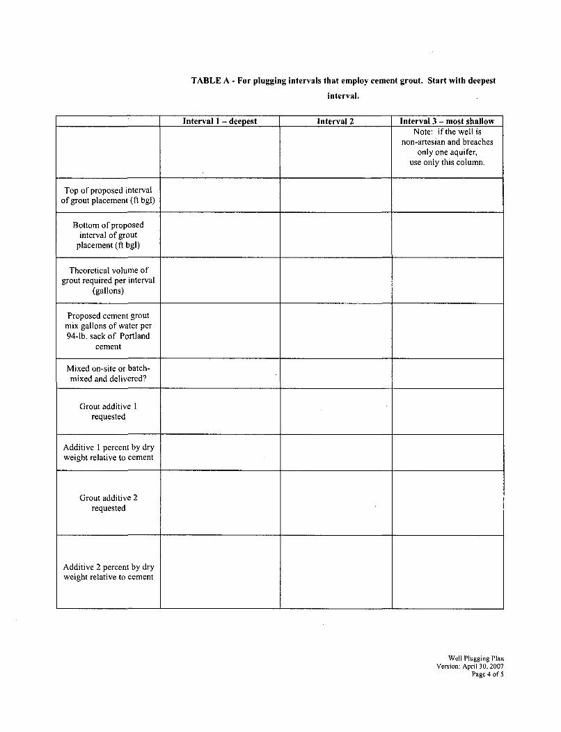
TABLE A - For plugging intervals that employ cement grout. Start with deepest
interval.
Interval I - deepest Interval 2 Interval 3 - most shallowNote: if the well is
non-artesian and breachesonly one aquifer,
use only this column.
Top of proposed intervalof grout placement (ft bgl)
Bottom of proposedinterval of grout
placement (ft bgl)
Theoretical volume ofgrout required per interval
(gallons)
Proposed cement groutmix gallons of water per94-lb. sack of Portland
cement
Mixed on-site or batch-mixed and delivered?
Grout additive Irequested
Additive 1 percent by dryweight relative to cement
Grout additive 2requested
Additive 2 percent by dryweight relative to cement
Well Plugging PlanVersion: April 30, 2007
Page 4 of 5
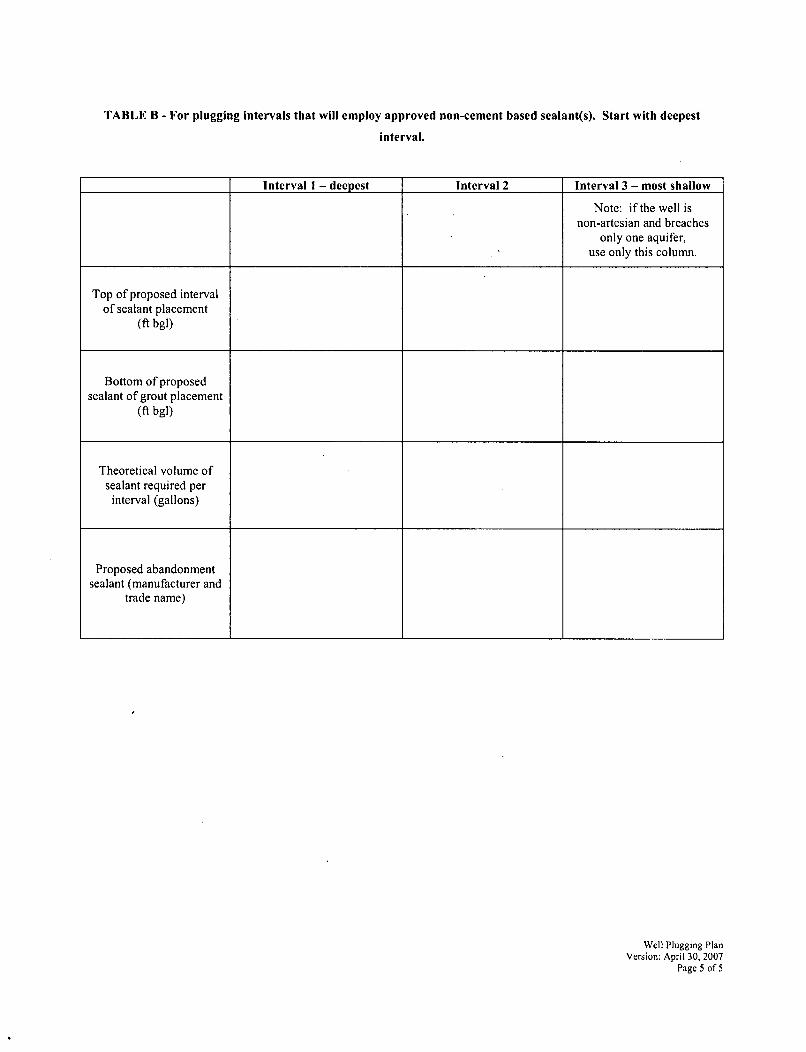
TABLE B - For plugging intervals that will employ approved non-cement based sealant(s). Start with deepest
interval.
Interval I - deepest Interval 2 Interval 3 - most shallow
Note: if the well isnon-artesian and breaches
only one aquifer,use only this column.
Top of proposed intervalof sealant placement
(ft bgl)
Bottom of proposedsealant of grout placement
(ft bgl)
Theoretical volume ofsealant required per
interval (gallons)
Proposed abandonmentsealant (manufacturer and
trade name)
Well Plugging PlanVersion: April 30, 2007
Page 5 of 5
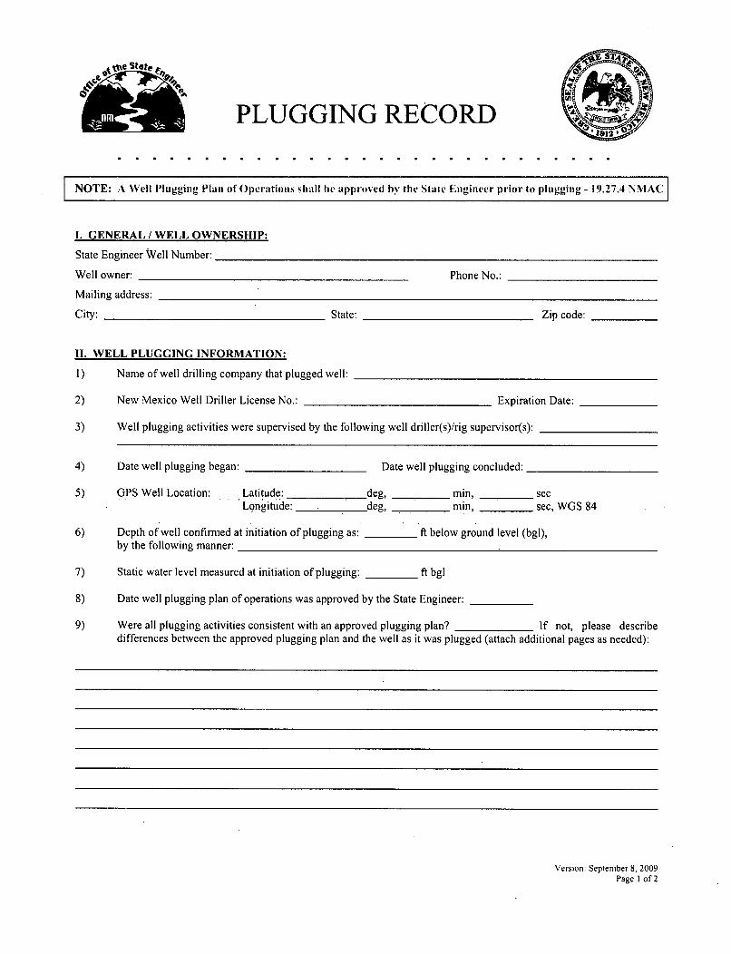
EPLUGGING RECORD
NOTE: A W'ell PIlugging Plan of Operations shall be approved by the State EIgineer prior to plugging - 19.27.4 NMAC
I. GENERAL / WELL OWNERSHIP:
State Engineer Well Number:
Well owner: Phone No.:
Mailing address:
City: State: Zip code:
11. WELL PLUGGING INFORMATION:
I) Name of well drilling company that plugged well:
2) New Mexico Well Driller License No.: Expiration Date:
3) Well plugging activities were supervised by the following well driller(s)/rig supervisor(s):
4) Date well plugging began: Date well plugging concluded:
5) GPS Well Location: Latitude: .deg, rmin, secLongitude: .deg, amin, sec, WGS 84
6) Depth of well confirmed at initiation of plugging as: ft below ground level (bgl),by the following manner:
7) Static water level measured at initiation of plugging: ft bgl
8) Date well plugging plan of operations was approved by the State Engineer:
9) Were all plugging activities consistent with an approved plugging plan? If not, please describedifferences between the approved plugging plan and the well as it was plugged (attach additional pages as needed):
Version: September 8, 2009Page 1 of 2
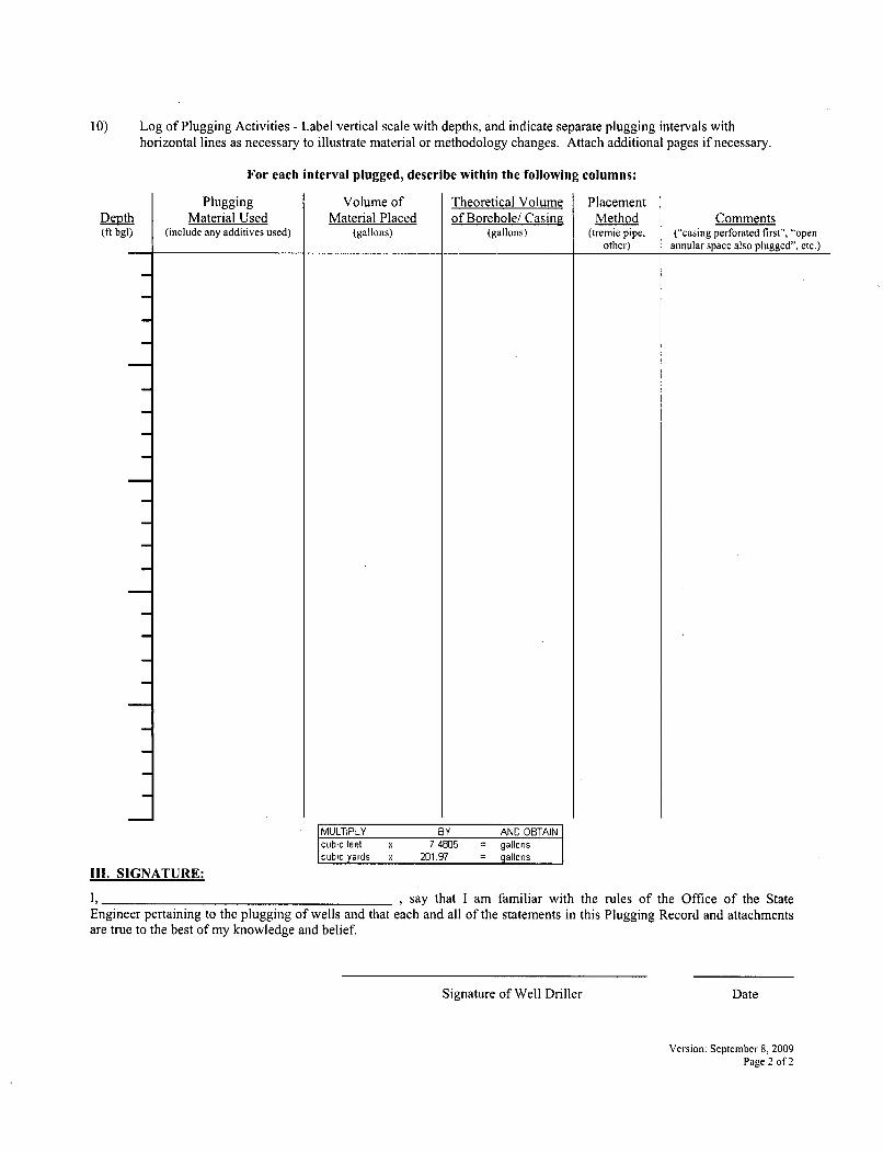
10) Log of Plugging Activities - Label vertical scale with depths, and indicate separate plugging intervals withhorizontal lines as necessary to illustrate material or methodology changes. Attach additional pages if necessary.
For each interval plugged, describe within the following columns:
Depth(ft bgl)
PluggingMaterial Used
(include any additives used)
Volume ofMaterial Placed
(gallons)
Theoretical Volumeof Borehole/ Casing
(gallons)
PlacementMethod
(tremie pipe.other)
Comments("casing perforated first", "open
annular space also plugged", etc.)
IMULTIPLY BY AND OBTAINcubic feet x 7.4805 = gallonscubic yards x 201.97 = allons
III. SIGNATURE:
I, , say that I am familiar with the rules of the Office of the StateEngineer pertaining to the plugging of wells and that each and all of the statements in this Plugging Record and attachmentsare true to the best of my knowledge and belief.
Signature of Well Driller Date
Version: September 8, 2009Page 2 of 2