roadmaps for independent fixed and mobile network … · roadmaps for independent fixed and mobile...
TRANSCRIPT
Roadmaps for independent fixed and mobile network evolution
Grant Agreement number: 317762 Project acronym: COMBO Project title: COnvergence of fixed and Mobile BrOadband access/aggregation networks Funding Scheme: Collaborative Project – Integrated Project
Date of latest version of the Deliverable 2.2: 20-06-2014
Leader of the deliverable: TID
Version: V2.0
Authorisation code: PU = Public
Project coordinator name, title and organisation: Jean-Charles Point, JCP-Consult
Tel: + 33 2 23 27 12 46
E-mail: [email protected]
Project website address: www.ict-combo.eu
PROPRIETARY RIGHTS STATEMENT THIS DOCUMENT CONTAINS INFORMATION, WHICH IS PROPRIETARY TO THE COMBO CONSORTIUM. NEITHER THIS DOCUMENT NOR THE INFORMATION CONTAINED HEREIN SHALL BE USED, DUPLICATED OR COMMUNICATED BY ANY MEANS TO ANY THIRD PARTY, IN WHOLE OR IN PARTS, EXCEPT WITH THE PRIOR WRITTEN CONSENT OF THE COMBO CONSORTIUM THIS RESTRICTION LEGEND SHALL NOT BE ALTERED OR OBLITERATED ON OR FROM THIS DOCUMENT

Page 2 of 127
Executive Summary of the Deliverable The main general COMBO target is to allow the convergence of fixed and mobile networks, where these both networks come together to an optimal and seamless quality of experience for the end user together with an optimized network infrastructure ensuring increased performance, reduced cost and reduced energy consumption. Under this general objective, WP2 defines the preliminary work on fixed, mobile and converged networks in order to put the basis for the remaining work packages, specifying the reference framework for fixed and mobile networks, the most relevant FMC (Fixed Mobile Convergence) network use cases and the requirements that will be the base of the COMBO project architecture. Inside WP2, the objective of Task 2.2 “Fixed and mobile network evolution” is to investigate the fixed and mobile evolution paths over time starting from the current trends. Task 2.2 is the first task completed inside WP2 (at month 8), which is the first technical work package inside the COMBO project, and it provides the initial studies regarding fixed and mobile network technologies and architectures to other tasks, not only at WP2 level, but also at project level. Task 2.2 is mainly fed by the work done in Task 2.1 regarding the reference framework and FMC network use cases. Task 2.2 has not only covered all technologies referred in Task 2.1, but has also followed other WPs activities in order to include all information expected by them. Task 2.2 is focused on both fixed and mobile networks, including access and aggregation network segments. The methodology used in this task has followed the next steps: • The analysis of the state of the art, identifying the most relevant network
technologies and architectures. The state of the art includes only the technologies and architectures implemented and used today in commercial deployments, or that are ready to be deployed.
• The analysis of evolution paths over time, with new technologies and architectures that could be commercially deployed, with a 2020 time horizon from the viewpoint of non-converged networks, and following their own path without considering future FMC networks architectures.
• Taking into account the previous activities, one roadmap have been established for fixed and one roadmap for mobile networks, including the most important dates in which the different technologies are expected to be available as standard, prototype or ready for deployment.
Fixed and mobile networks remain mainly independent and FMC is currently limited to some areas in which fixed networks can be used to connect the base stations to the mobile network elements, such as the mobile backhaul or the fixed IP backbone. The state of the art studies have shown that the main wired technologies used in today’s access network are based on copper (xDSL), cable (DOCSIS) and fibre optic (FTTx), analysing their current status and limitations. Fixed wireless technologies, like Wi-Fi and microwaves and mobile technologies, mainly 2G, 3G and LTE have also presented in their respective state of the art, with a higher emphasis on LTE as it is the last mobile technology currently deployed. In the aggregation network state of
Page 3 of 127
the art current technologies like SONET/SDH, Ethernet, MPLS and wavelength switched optical networks have been identified as the most used today analysing their latest status. Current drivers on fixed and mobile networks, like resource usage, cost and energy efficiency, enhanced scalability, reliability, delay and reach as the main fixed network drivers and the increasing data traffic, the growth of the number of connected devices and the diversification of services and equipment as the main mobile network ones, are being considered in the definition and development of the network evolution:
• in wired technologies, such as long reach PON, G.fast, FTTdp, NG-PON2 and WDM-PON,
• in fixed wireless, like the new work on hotspots, network-assisted Wi-Fi, and MIMO and non-line-of-sight transmission on microwaves frequencies,
• in aggregation networks, such as the integration with access networks, and GMPLS and SDN new topics,
• and in mobile networks, including LTE-Advance, heterogeneous networks, back and front office, synchronization, C-RAN, mobile offloading and self-organizing networks.
Although this document is mainly oriented to independent fixed and mobile networks, some initiatives dealing with both fixed and mobile have been identified and analysed, such as the seamless integration of Wi-Fi and mobile technologies, mobile backhaul and fronthaul, traffic offloading mechanisms and new optical architectures that can be used to provide connectivity to both fixed and mobile services. These technologies are presented using two roadmaps for fixed and mobile networks evolution including the most important dates in which the different technologies will be available as standard, prototype or ready for deployment. They are depicted in Figure 50 and Figure 73. The current state of the art of fixed and mobile networks and its evolution is needed to specify which kind of technologies and architectures are deployed now and to know which new technologies will be available and what architectural changes fixed and mobile networks could face in the future. That is important in order to know how these networks are deployed today and what technological tools will be available with a 2020 time horizon. This knowledge is key to perform the following tasks:
• To define the reference framework as the starting point for the project covering today’s network status. That network status is defined by the technologies and architectures deployed nowadays, which are covered in the state of the art chapters of this deliverable.
• To propose challenging but feasible, with a 2020 time horizon, FMC network uses cases in WP2 and to specify useful requirements and KPIs.
• To design beyond state of the art FMC network architectures in WP3, taking into account what is now deployed and the future technologies that will be available.
• To provide different deployed network technologies to initiate WP5 techno-economic studies during the first project year.

Page 4 of 127
• To identify the most interesting technologies from an FMC perspective. That will focus the activities of WP4 and WP6 regarding the performance monitoring and the development and experimental activities respectively, in activities beyond of the state of the art.
Other tasks inside WP2 are complementary to Task 2.2 activities, such as the definition of the reference framework and FMC network use cases (Task 2.1), the study of current traffic demands and forecast and traffic modelling (Task 2.3) and the specification of FMC requirements and KPIs (Task 2.4).

Page 5 of 127
List of authors Full Name – E-mail Company – Country Code
E. Bogenfeld ([email protected]) F. Geilhardt ([email protected])
DTAG - DE
J. Torrijos Gijón ([email protected]) L. Cucala ([email protected]) M. Arroyo ([email protected])
TID - ES
J. De Biasio ([email protected]) G. Akpoli ([email protected]) T. Thierno ([email protected]) X. Grall ([email protected])
FT - FR
V. Sestito ([email protected]) ALU-I - IT A. Hamidian ([email protected]) EAB - SE A. Magee ([email protected]) P. Turnbull ([email protected])
ADVA-UK - UK
S. Höst ([email protected]) ULUND - SE A. Krendzel ([email protected]) R. Martínez ([email protected])
CTTC – ES
A. Pattavina ([email protected]) M. De Andrade ([email protected])
POLIMI - IT
K. Grobe ([email protected]) ADVA – DE J. V. Galan ([email protected]) TELNET - ES
Page 6 of 127
Table of Content 1 INTRODUCTION 12
2 STATE OF THE ART OF FIXED NETWORKS 14
2.1 COPPER ACCESS STATE OF THE ART 14 2.1.1 DIGITAL SUBSCRIBER LINE 14 2.1.2 OTHER TECHNIQUES: BONDING AND VECTORING 15 2.2 CABLE ACCESS STATE OF THE ART 16 2.2.1 CABLE NETWORKS INTRODUCTION 16 2.2.2 DOCSIS 3.0 IN HFC 17 2.2.3 PACKETCABLE 18 2.3 OPTICAL ACCESS STATE OF THE ART 19 2.3.1 FTTX INTRODUCTION 19 2.3.1.1 BPON, GPON and EPON 20 2.3.1.2 10G-‐EPON and 10G-‐GPON 21 2.3.2 POINT TO MULTIPOINT WITH LOGICAL POINT TO POINT: WDM-‐PON 22 2.4 FIXED WIRELESS ACCESS STATE OF THE ART WI-‐FI 25 2.4.1 WI-‐FI RADIO TECHNOLOGY STATE OF THE ART 25 2.4.2 WI-‐FI SECURITY 27 2.4.3 WI-‐FI TECHNOLOGY AS ACCESS NETWORK 29 2.5 MICROWAVE 33 2.5.1 ADAPTIVE MODULATION 35 2.5.2 MILLIMETRE-‐WAVE TRANSMISSION 36 2.6 AGGREGATION NETWORK STATE OF THE ART 37 2.6.1 SONET/SDH TRANSPORT 38 2.6.2 CARRIER-‐GRADE ETHERNET SERVICES 38 2.6.3 ETHERNET SERVICE OVER MPLS, MPLS-‐TP AND S-‐MPLS 39 2.6.4 WAVELENGTH SWITCHED OPTICAL NETWORKS 40
3 STATE OF THE ART OF MOBILE NETWORKS 42
3.1 2G 42 3.2 3G 42

Page 7 of 127
3.3 LTE 43 3.4 CURRENT MOBILE BACKHAUL ALTERNATIVES 45 3.5 TRAFFIC OFFLOADING 46 3.5.1 WI-‐FI OFFLOADING TECHNIQUE 47 3.5.2 FEMTO-‐OFFLOADING 49
4 FIXED EVOLUTION TRENDS 51
4.1 INTRODUCTION: DRIVERS FOR EVOLUTION OF FIXED ACCESS NETWORKS 51 4.2 COPPER ACCESS EVOLUTION 52 4.2.1 G.FAST 52 4.2.2 PHANTOMING 53 4.3 CABLE ACCESS EVOLUTION 53 4.3.1 UPGRADE FROM DOCSIS 3.0 TO DOCSIS 3.1 53 4.3.2 ETHERNET PON OVER COAX (EPOC) ARCHITECTURE 54 4.3.3 MOBILE BACKHAUL USING CABLE TECHNOLOGIES 54 4.3.4 INTERNET PROTOCOL (IP) MIGRATION AND CONVERGENCE 55 4.4 OPTICAL ACCESS EVOLUTION 55 4.4.1 NEXT GENERATION PON VERSION 2 (NG-‐PON2) 55 4.4.1.1 Introduction 55 4.4.1.2 NG-‐PON2 migration issues 56 4.4.1.3 NG-‐PON2 impact on small cells 58 4.4.2 WDM-‐PON EVOLUTION 60 4.4.3 OFDM-‐PON 63 4.5 FIXED WIRELESS EVOLUTION: WI-‐FI EVOLUTION 64 4.5.1 WI-‐FI RADIO STANDARD EVOLUTION 64 4.5.2 WI-‐FI ARCHITECTURE ENHANCEMENTS 65 4.5.3 WI-‐FI HOTSPOT UTILIZATION ENHANCEMENT 65 4.5.4 NETWORK-‐ASSISTED WI-‐FI ACCESS SELECTION FOR MOBILE DEVICES 65 4.6 MICROWAVE EVOLUTION 66 4.6.1 NEW FREQUENCY BANDS 67 4.6.2 LOS MIMO 67 4.6.3 NLOS TRANSMISSION ON MICROWAVE FREQUENCIES 68 4.7 ACCESS ARCHITECTURES EVOLUTION PROPOSALS 69 4.7.1 LONG REACH PON AND CENTRAL OFFICE CONSOLIDATION 69
Page 8 of 127
4.7.1.1 Research Challenges 70 4.7.2 FIBRE TO THE DISTRIBUTION POINT 72 4.7.3 WIRELESS SOLUTIONS FOR FIXED BROADBAND REPLACEMENT 73 4.7.3.1 General architecture for WLD 73 4.7.3.2 Operating scenarios for WLD 74 4.7.3.3 Candidate technologies for the WLD radio link 75 4.8 AGGREGATION NETWORK EVOLUTION 76 4.8.1 KEY BLOCKS OF AN INTEGRATED METRO -‐ AGGREGATION NETWORK 78 4.8.2 CONTROL PLANE SOLUTIONS WITHIN THE AGGREGATION NETWORK 80 4.8.2.1 Centralized SDN Control Plane 80 4.8.2.2 Distributed GMPLS Control Plane 81 4.9 ROADMAP FOR FIXED NETWORK EVOLUTION 83
5 MOBILE EVOLUTION TRENDS 86
5.1 INTRODUCTION: DRIVERS FOR EVOLUTION OF MOBILE ACCESS NETWORKS 86 5.2 TECHNOLOGY EVOLUTION FOR INCREASED CAPACITY 87 5.2.1 LTE-‐ADVANCED AND COMP 87 5.2.1.1 LTE-‐A requirements 87 5.2.1.2 LTE-‐A features 87 5.2.1.3 Impacts of LTE-‐A features 88 5.2.1.4 CoMP 91 5.2.2 HETEROGENEOUS NETWORKS 93 5.2.2.1 Heterogeneous network definitions and types 93 5.2.2.2 Deployment scenarios 94 5.2.2.3 Interworking with EPC 95 5.3 FIXED INFRASTRUCTURE EVOLUTION OF MOBILE NETWORKS 97 5.3.1 MOBILE BACKHAUL EVOLUTION 97 5.3.1.1 Global mobile backhaul evolution 97 5.3.1.2 Transport IP evolution 97 5.3.2 MOBILE FRONTHAUL EVOLUTION 98 5.3.3 SYNCHRONIZATION 101 5.3.4 CLOUD RAN 105 5.4 NETWORK MANAGEMENT EVOLUTION 109 5.4.1 SELF-‐ORGANIZING NETWORKS 109

Page 9 of 127
5.4.1.1 SON definition and self-‐x functionalities 110 5.4.1.2 SON status and evolution within NGMN, 3GPP, and several R&D projects 111 5.5 ROADMAP FOR MOBILE EVOLUTION 112
6 CONCLUSIONS 114
7 REFERENCES 116
List of Tables Table 1: BPON, GPON & EPON main characteristics ............................................................................. 21
Table 2: 10G-‐EPON and 10G-‐GPON main characteristics ..................................................................... 22
Table 3: Main properties of latest Wi-‐Fi standards .............................................................................. 26
Table 4: Comparison of main characteristics of LR-‐PON architectures ................................................ 72
Table 5: LTE-‐advance features in 3GPP releases .................................................................................. 88
Table 6 Synchronization Requirements for Various Mobile Air Interfaces ......................................... 103
List of Figures
Figure 1: Work structure of COMBO project ........................................................................................ 12
Figure 2: A general DSL connection ...................................................................................................... 14
Figure 3: Typical topology of the existing infrastructure in a telephony grid. ...................................... 15
Figure 4: DOCSIS 3.0 Hybrid Coaxial cable architecture [2] .................................................................. 17
Figure 5: PacketCable 2.0 architecture ................................................................................................. 19
Figure 6: Passive optical network topology .......................................................................................... 20
Figure 7: Concept of passive WDM with coloured interfaces in AGS and DSLAM ................................ 22
Figure 8: Tuning and supervision of tunable pluggables in pWDM ...................................................... 23
Figure 9: pWDM / WDM-‐PON based on tunable lasers for broadband P2MP access or backhaul ...... 23
Figure 10: Seeded/reflective WDM-‐PON with RSOA or IL-‐FP laser ...................................................... 24
Figure 11: IRZ/RZ wavelength-‐re-‐use WDM-‐PON ................................................................................. 25
Figure 12: Channelization of the 2.4 GHz and 5 GHz bands. ................................................................ 26
Figure 13: Wi-‐Fi frequency bands. ........................................................................................................ 27
Figure 14: 802.1X port controlled mechanism ..................................................................................... 29
Figure 15: Wi-‐Fi public architecture centralized model ........................................................................ 30

Page 10 of 127
Figure 16: Wi-‐Fi public architecture distributed model ........................................................................ 30
Figure 17: Community Wi-‐Fi hotspot dedicated device ....................................................................... 31
Figure 18: Community Wi-‐Fi hotspot broadband gateway .................................................................. 31
Figure 19: Business Wi-‐Fi hotspot ........................................................................................................ 32
Figure 20: Operator Wi-‐Fi hotspot ........................................................................................................ 32
Figure 21: Backhaul physical medium, from [15] ................................................................................. 33
Figure 22: Principle of adaptive modulation (copyright Ericsson AB) ................................................... 35
Figure 23: Throughput versus channel bandwidth (copyright Ericsson AB) ......................................... 36
Figure 24: (Left) Maximum hop length versus link gain and rain intensity; (Right) 5 min/year rain zones in Europe (copyright Ericsson AB) .............................................................................................. 37
Figure 25: Deployment of WDM networks within aggregation / metro segments. ............................. 40
Figure 26: Demarcation points in mobile backhaul .............................................................................. 46
Figure 27: WLAN 3GPP IP access .......................................................................................................... 47
Figure 28: IFOM scenario ...................................................................................................................... 48
Figure 29: MAPCON scenario ............................................................................................................... 49
Figure 30: LIPA/SIPTO-‐Femto scenario ................................................................................................. 50
Figure 31: SIPTO-‐Macro scenario ......................................................................................................... 50
Figure 32: Co-‐existence scenarios, (A) full ODN and (B) feeder only .................................................... 58
Figure 33: WDM-‐PON technology roadmap, based on FP7 IP OASE WP4 ............................................ 60
Figure 34: Low-‐cost tunable-‐laser-‐based WR-‐WDM-‐PON .................................................................... 60
Figure 35: Heterodyne Co-‐UDWDM-‐PON using filter plus splitter ODN .............................................. 61
Figure 36: Homodyne detection without polarization diversity and without 90° hybrids ................... 62
Figure 37: OAM aspects of WDM-‐PON. A: OTDR monitoring. B: protection enabled by 2:N AWGs .... 62
Figure 38: OFDMA-‐PON general architecture ...................................................................................... 63
Figure 39: Backhaul physical medium globally and in Europe [15] ...................................................... 66
Figure 40: Principle of LOS MIMO [16] (copyright Ericsson AB) ........................................................... 68
Figure 41: General architecture of a Long Reach PON: Branch and Tree architecture ........................ 69
Figure 42: General architecture of a Long Reach PON: Ring and Spur architecture ............................. 70
Figure 43: Wireless Local Drop main elements .................................................................................... 74
Figure 44 Multi-‐service integrated aggregation network segment ...................................................... 77
Figure 45 Wavelength conversion options for OTN and packet (MPLS-‐TP) technologies .................... 78
Figure 46 Wavelength routing options (FOADM and R/TOADM) ......................................................... 79
Figure 47 “O-‐O-‐O” interconnect between access and aggregation networks ...................................... 80
Figure 48 Centralized SDN control plane architecture ......................................................................... 81
Page 11 of 127
Figure 49 – Distributed GMPLS control plane and API between the applications and EMS/NMS ....... 82
Figure 50 Roadmap for fixed network evolution .................................................................................. 85
Figure 51: Coordinated Scheduling/Coordinated Beamforming CoMP ................................................ 91
Figure 52: Joint transmission CoMP ..................................................................................................... 92
Figure 53: Central and distributed CoMP processing ........................................................................... 93
Figure 54: EPS mobility architecture in heterogeneous networks ....................................................... 96
Figure 55: Starting point: IP RAN + L3 VPN based Mobile Backhaul ..................................................... 97
Figure 56: Mobile backhaul objective: Seamless L3VPN ...................................................................... 98
Figure 57 Simplified view of mobile fronthaul / backhaul network and associated components ........ 99
Figure 58 Basic alternatives for CPRI fronthauling ............................................................................. 100
Figure 59 Frequency Synchronisation ................................................................................................. 101
Figure 60 Phase Synchronisation ........................................................................................................ 101
Figure 61 Time Synchronisation ......................................................................................................... 102
Figure 62 Transport of Time/Frequency using 1588v2-‐ Desired Goal ................................................ 104
Figure 63 Transport of Time/Frequency using 1588v2-‐ Realistic/Future Proof Architecture ............ 104
Figure 64 Migration towards C-‐RAN ................................................................................................... 106
Figure 65 BBU under the tower in a 3G scenario ............................................................................... 106
Figure 66 BBU hoteling in an LTE scenario ......................................................................................... 106
Figure 67 Possible functional separation between BBU and RRU. GPS: Global Positioning System, PA: Power Amplifier, LNA: Low-‐Noise Amplifier ....................................................................................... 107
Figure 68 Avoidance of ICI through C-‐RAN ......................................................................................... 107
Figure 69 Energy consumption of mobile network (left) and of base station (middle), and cell-‐site related energy saving through C-‐RAN compared to macro BS approach (right) [104] ....................... 108
Figure 70 Tidal effect in residential and business area ....................................................................... 108
Figure 71 C-‐RAN as part of the complete mobile infrastructure ........................................................ 109
Figure 72: Basic self-‐x cycle ................................................................................................................ 110
Figure 73 – Roadmap for mobile network evolution .......................................................................... 113
APPENDIX A – Glossary …………………………………………………………………… 123

Page 12 of 127
1 INTRODUCTION Figure 1 shows the scope of this document in the context of the whole COMBO project. In this respect, this document covers the box “Technology” with the target to describe the starting situation for the FMC study in COMBO. This includes the study of the state of the art and the current evolution trends of both fixed and mobile network. This study is focused on the access and the aggregation networks as the COMBO concept proposes a unified access and aggregation network architecture allowing fixed and mobile networks to converge. It also includes an analysis of the future fixed and mobile evolution paths over time considering a 2020 time horizon in order to establish one roadmap for fixed and mobile networks, respectively. The study results serve mainly as a reference for comparison with the FMC network scenarios defined in WP3 but also for other work packages as a base of their studies.
Figure 1: Work structure of COMBO project
Following, this document is structured in five chapters:
• Chapter 2 includes the current state of the art of fixed networks, considering both wireline (from the most traditional copper-based to new fibre-based networks) and wireless technologies and architectures (such as Wi-Fi and microwave). Additionally the state of the art of the aggregation network is considered in this section.
Page 13 of 127
• Chapter 3 covers the current state of the art of mobile networks, including 2G, 3G and Long Term Evolution (LTE) systems, analysing the current alternatives to provide connectivity to base stations.
• Chapter 4 analyses the future evolution of fixed access networks, identifying the main drivers for that evolution and covering the most important trends in wireline and wireless technologies and access architectures such as long-reach PON or fibre to the distribution point. Aggregation network evolution is also analysed in this section, covering future integrated networks and control plane trends. As a summary of this section, a common roadmap for fixed networks up to 2020 is established.
• Chapter 5 details the future evolution of mobile networks using the same approach as in fixed networks. In this case, future trends for increased capacity in mobile networks (such as LTE-Advanced and others), infrastructure evolution and enablers (like mobile backhaul and fronthaul, Cloud RAN, etc.) and network management evolution (with self-organizing networks for example) have been analysed. Additionally, this section establishes a common roadmap for mobile networks up to 2020.
• Chapter 6 contains the conclusions.

Page 14 of 127
2 STATE OF THE ART OF FIXED NETWORKS This chapter analyses the main technologies and architectures in fixed broadband access and aggregation networks that are currently deployed and in use by network operators or are based on finalized standards and are close to be deployed. The fixed part of the core network is not included in the scope of this study as COMBO considers that access and aggregation networks are the priority. Today’s network segments are described in deliverable D2.1. The study considers the main wired technologies, such as copper and optical technologies used in the access networks, and wireless technologies, like Wi-Fi and microwaves. Other technologies such as Broadband Power Line (BPL), WiMAX (Worldwide Interoperability for Microwave Access) or Broadband over Satellite have not been included in this study as they are less deployed in the current networks and they will not be part of future studies in COMBO.
2.1 Copper access state of the art
2.1.1 Digital Subscriber Line Digital Subscriber Line (DSL) covers the copper based standards reusing the existing infrastructure connecting the customer to the telephony grid, such as SDSL, HDSL, SHDSL, ADSL and VDSL. The overall idea is to utilize and leverage the old, already existing, telephony infrastructure to provide customers broadband services, such as internet access. In general terms, all Digital Subscriber Line (DSL) techniques can be described as in Figure 2. In the telephony grid, each customer is connected in a star-like network to a DSL Access Multiplexer (DSLAM) in the central node. In the earlier standards like ADSL, the DSLAM is located in the Central Office (CO), where the local telephone switch is also located. Then, optical fibre connects the CO to the Internet. The voice and data signals are physically separated both in the DSLAM and in the Customer Premises Equipment (CPE), but both signals are sent in a Frequency-Division Multiplexing (FDM) transmission over the twisted-pair copper lines in the telephony loop to deliver Internet access.
Figure 2: A general DSL connection
Several DSL technologies have been standardized up to now: Asymmetric Digital Subscriber Line (ADSL) was standardized in 1999 [ITU-T G.992.1], ADSL2plus in 2002 [ITU-T G.993.5] and Very High Bit Rate DSL (VDSL2) in 2006 [ITU-T G.993.2]. For this technique, the DSL signals can use a much higher frequency band, up to 30

Page 15 of 127
MHz, to reach bit rates in the order of dozens of Mb/s. To use these frequencies, the length of the loop must be shorter than in ADSL. For loops that are shorter than 1.5 km (50% of the customers in some European countries), VDSL provides more capacity than ADSL. This means that the fibre connection should be deployed further out in the telephony grid, up to the cabinet, see Figure 3.
Figure 3: Typical topology of the existing infrastructure in a telephony grid.
In 2011, ITU-T started working on a new standardization project called G.fast, where the fibre roll out will continue up to the last distribution point (DP) in the copper grid. G.fast is described in section 4.2.1..
2.1.2 Other techniques: bonding and vectoring In VDSL2, crosstalk is a primary limitation and its effect dominates loops shorter than 1 km. The most relevant type of crosstalk in VDSL2 and ADSL2+ is FEXT (Far End CrossTalk), consisting of the interference of one line’s signal over the signal that travels in the neighbour pairs along the cable propagating in the same direction. Vectoring minimizes the effect of the crosstalk (FEXT) in both transmission directions, downstream and upstream, by means of interference cancellation. Vectoring in VDSL2 systems is defined in the ITU-T Recommendation G.993.5. Vectoring is optimal for cables shorter than 1 km and without FEXT coming from non-vectored systems (without unbundling). Literature states that for poorly isolated cables and little twisting, some improvement can still be achieved for loops between 1 and 1.4 km. If noise other than FEXT interference is very high, the positive effects of vectoring are highly diminished. Moreover, if a cable has multiple binders, vectoring gain will be higher when applied to the whole cable since coupling from different binders, although slightly, affects the victim pair. Bonding is the simultaneous use of multiple DSL pairs to improve total throughput. In bonding, the data channel of multiple DSL pairs is actually bonded, not anything at the physical layer. The throughput of a set of n bonded DSL pairs is approximately the sum of the rates of the individual DSL pairs. Therefore, n twisted pairs should achieve n times the rate of any individual pair alone. The overall rate may differ from this slightly, since a small amount of extra framing information must be transmitted so that the bits received at

Page 16 of 127
the far end can be reassembled in the correct order, even though the delays on the individual pairs may be slightly different. ITU Recommendations G998.1 and G998.2 provide details for bonding arbitrary types of DSL pairs at either the ATM or the Ethernet layers. Bonding has several challenges to overcome. It obviously requires at least two twisted pairs running to the respective home, which is not always the case. Moreover, bonding introduces complexity in management due to the need of tracking two or more pairs when provisioning the DSL service. Further, bonding has no inner mechanisms to recover bonded transmission whenever one of the pairs resynchronises, thus the whole system needs to be reinitialised manually to achieve bonding rates again.
2.2 Cable access state of the art
2.2.1 Cable networks introduction Originally, cable TV networks were only configured for one-way transmission of TV and radio programmes from the operator to subscribers. In order to offer telephony and broadband Internet access, operators upgraded their networks to allow two-way transmission, creating next generation cable TV networks, which are typically hybrid fibre coaxial (HFC) networks. The network has a tree-and-branch or star architecture and distributes signals via optical fibre from the operator’s central premises to optical nodes, and via coaxial cables from the optical nodes to the subscriber’s premises. Typically, the coaxial cable is a shared medium. Where in telephone networks each subscriber is connected by his own twisted copper pair, in a cable TV network a group of subscribers shares the same coaxial cable. For Internet access (and VoIP telephony), cable modems are installed at the subscribers’ premises and a cable modem termination system (CMTS) at the operator. The transmission of signals between the CMTS and the cable modems has been standardised by ITU-T as DOCSIS (Data Over Cable Service Interface Specification). The European versions of this standards family (which are specified in annexes of the ITU-T SG9 recommendations) are called EuroDOCSIS. These standards specify the physical transmission between the CMTS and cable modems over either all-coaxial or hybrid fibre coaxial networks, higher protocol layers (in particular using the Internet Protocol) and security measures (as different subscribers use the same coaxial cable, the signals must be encrypted). Cable operators have addressed fixed-mobile convergence issues since 2006, and produced specifications for instance on interconnection between PacketCable and IMS architectures. There is a growing interest from cable operators on FMC, however the current process especially in Europe is mostly to endorse CableLabs work. The technical work is driven by American Multiple System Operators (MSOs) mostly, through CableLabs. CableLabs produces technical reports and specifications that were usually endorsed by the Society of Cable Telecommunications Engineers (SCTE) and submitted to ITU-T. These specifications are usually adapted to European requirements, and then endorsed by the European Telecommunications Standards Institute (ETSI).
Page 17 of 127
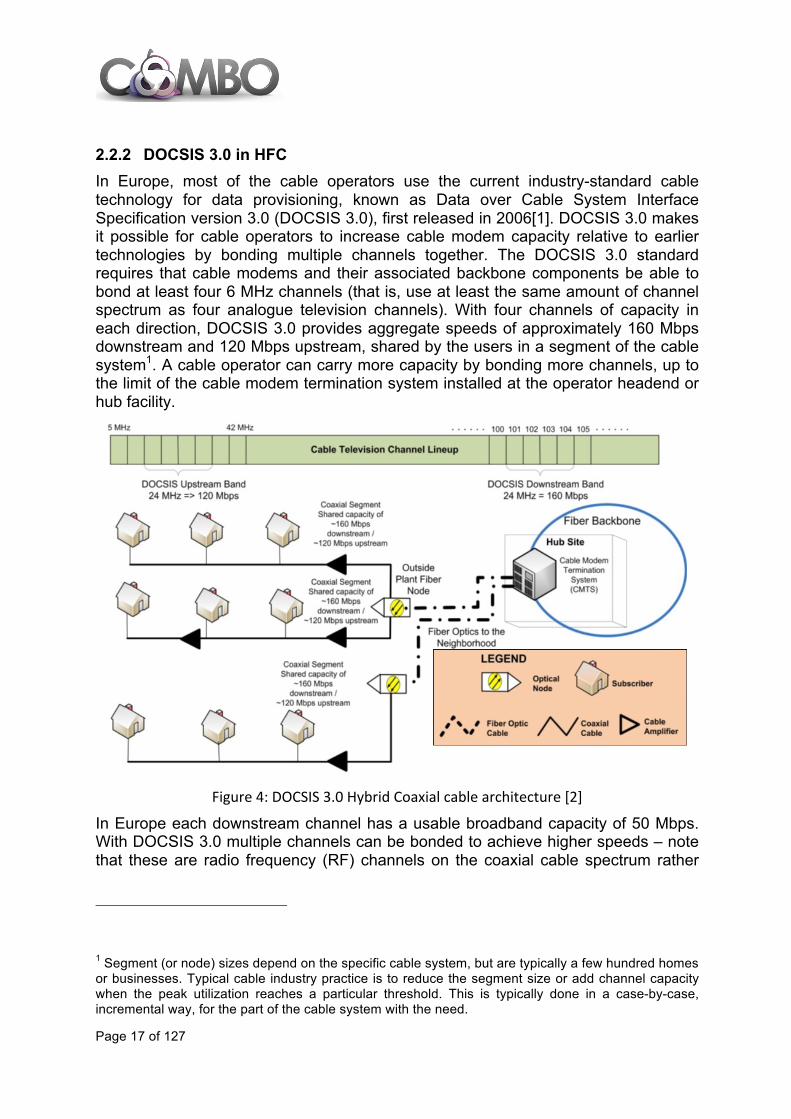
2.2.2 DOCSIS 3.0 in HFC In Europe, most of the cable operators use the current industry-standard cable technology for data provisioning, known as Data over Cable System Interface Specification version 3.0 (DOCSIS 3.0), first released in 2006[1]. DOCSIS 3.0 makes it possible for cable operators to increase cable modem capacity relative to earlier technologies by bonding multiple channels together. The DOCSIS 3.0 standard requires that cable modems and their associated backbone components be able to bond at least four 6 MHz channels (that is, use at least the same amount of channel spectrum as four analogue television channels). With four channels of capacity in each direction, DOCSIS 3.0 provides aggregate speeds of approximately 160 Mbps downstream and 120 Mbps upstream, shared by the users in a segment of the cable system1. A cable operator can carry more capacity by bonding more channels, up to the limit of the cable modem termination system installed at the operator headend or hub facility.
Figure 4: DOCSIS 3.0 Hybrid Coaxial cable architecture [2]
In Europe each downstream channel has a usable broadband capacity of 50 Mbps. With DOCSIS 3.0 multiple channels can be bonded to achieve higher speeds – note that these are radio frequency (RF) channels on the coaxial cable spectrum rather
1 Segment (or node) sizes depend on the specific cable system, but are typically a few hundred homes or businesses. Typical cable industry practice is to reduce the segment size or add channel capacity when the peak utilization reaches a particular threshold. This is typically done in a case-by-case, incremental way, for the part of the cable system with the need.

Page 18 of 127
than physical cables. DOCSIS 3.0 has no limit on the number of channels that can be aggregated, as long as they fit into the available RF spectrum. Limits arise from the capabilities of the CMTS and the CPE. The cable operator must also decide on the most appropriate (and profitable) split between television and broadband services. Commercially available DOCSIS 3.0 equipment can provide:
• Download capacity of 400 Mbps (8 channels) on the DOCSIS CPE • Upload capacity of 120 Mbps (4 channels) on the DOCSIS CPE
The downstream broadband channel in a DOCSIS network is a shared medium. The service level and sustainable bit rate will depend on the number of concurrently active subscribers on the segment of coaxial cable. A single optical node in a big city can serve up to several thousand homes, connected over the same optical fibre. As a result, operators needing to upgrade the cable plant to cope with bandwidth growth are segmenting the network into smaller sharing groups of 500 homes, and even only 250 or 100 homes in some cases, by:
• connecting individual fibres to each fibre node, • dividing the fibre nodes into two or more smaller fibre nodes, or • bringing fibre to the last amplifier (FTTLA) to service an even smaller group of
homes. DOCSIS 3.0 supports the IPv6 protocol in addition to IPv4. With regard to security, DOCSIS 3.0 uses the current state-of-the-art encryption algorithm AES (Advanced Encryption Standard) instead of the former DES algorithm, which is being increasingly considered as insecure.
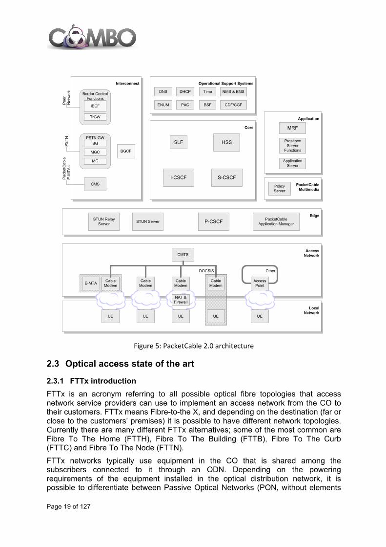
2.2.3 PacketCable PacketCable is a consortium founded by CableLabs to define standards to provide IP multimedia services over HFC networks on top of DOCSIS. Packet cable has evolved from telephony only services (Packet Cable 1.x) towards more general SIP based services by adopting IMS as the service control overlay. Packet cable 2.0 is aligned to IMS since 3GPP release 7. PacketCable 1.0 provides support for telephony applications using MGCP protocol. PacketCable 1.5 is a superset of version 1.0 and provides mainly SIP session management within and among packet cable networks. PacketCable multimedia is separate from the PacketCable 1.x specification and provides a service agnostic QoS and accounting framework. It may therefore be used for any multimedia application. PacketCable 2.0 adds support for SIP based end point, and a SIP-based service platform that may be used to support a variety of services. The Figure 5 presents the general PacketCable 2.0 architecture covering cable and mobile networks and providing a basis for cable-mobile convergence, as user equipment (UE) attached to different fixed or mobile networks can use PacketCable 2.0 services.
Page 19 of 127
Figure 5: PacketCable 2.0 architecture
2.3 Optical access state of the art
2.3.1 FTTx introduction FTTx is an acronym referring to all possible optical fibre topologies that access network service providers can use to implement an access network from the CO to their customers. FTTx means Fibre-to-the X, and depending on the destination (far or close to the customers’ premises) it is possible to have different network topologies. Currently there are many different FTTx alternatives; some of the most common are Fibre To The Home (FTTH), Fibre To The Building (FTTB), Fibre To The Curb (FTTC) and Fibre To The Node (FTTN). FTTx networks typically use equipment in the CO that is shared among the subscribers connected to it through an ODN. Depending on the powering requirements of the equipment installed in the optical distribution network, it is possible to differentiate between Passive Optical Networks (PON, without elements
Architecture Framework Technical Report PKT-TR-ARCH-FRM-V03-070925
9/25/07 CableLabs� 9
Application
LocalNetwork
AccessNetwork
Operational Support SystemsInterconnect
Core
PacketCableMultimedia
Edge
PresenceServer
Functions
S-CSCFCMS Policy
Server
STUN Server P-CSCF
I-CSCF
PSTN
Peer
Net
wor
k
PSTN GW
MG
MGC
SG
ApplicationServer
Border Control Functions
TrGW
IBCF
Pack
etC
able
E-
MTA
s
STUN Relay Server
Other
Access Point
ENUM
NMS & EMS
CDF/CGF
TimeDHCP
Cable Modem
CMTS
Cable Modem
Cable Modem
NAT & Firewall
Cable Modem
PacketCable Application Manager
SLF
BGCF
UE UE UE UE UE
DNS
HSS
DOCSIS
E-MTA
PAC BSF
MRF
Figure 1 - PacketCable Reference Architecture
The architecture provides a rich and modular platform upon which a variety of multimedia communication services can be built for a diverse set of UEs. Note the reference architecture depicts several different UE deployment scenarios (e.g., UE behind a CM, a NAT and Firewall gateway between the UE and CM). These deployment scenarios are meant to illustrate the fact that UEs can be deployed in many different environments and configurations. The reference architecture does not provide an exhaustive set of deployment scenarios.
PacketCable assumes a model composed of users, Public User Identities, UEs, and devices. For example, a user may have multiple User Equipment (UE) devices, each of which may be registered to one or more Public User Identities. A Public User Identity can be an E.164 number or it can be an alphanumeric identifier that makes sense in the context of a SIP Telephony service. Each Public User Identity is generally associated with a user.

Page 20 of 127
inside the ODN requiring electrical power) and Active Optical Networks (AON, with some elements that require it). Additionally FTTx networks can be deployed with a dedicated fibre for each subscriber, using a point-to-point (PtP) connection, or with a fibre that is shared by multiple subscribers, using a point-to-multipoint (PtMP) connection. PtP technologies in the access network can be based on different standards, such as ITU-T Recommendation G.986 1 Gb/s PtP Ethernet-based optical access system or IEEE 802.3ah. PtP technologies can use either a dedicated pair or a single fibre from the CO to the final users without the need of active elements in the ODN. PtP systems are often used to provide FTTH connectivity to business users or to provide backhaul connectivity to remote nodes in FTTB/C/N network topologies A P2P AON topology is also possible with network elements in the ODN (such as a router or a switch) requiring energy for their power supply to distribute signals to the end users (additional information can be found in [3]). A PON consists of an Optical Line Termination (OLT) located at the CO and multiple Optical Network Termination (ONT) that are connected to it through an ODN. Both sides, the OLT and the ONTs require power, however, the ODN is totally passive using power splitters/combiners or filters to divide passively the signal (e.g., in power or in bandwidth) among the subscribers (ONTs) connected to that ODN. Typically the number of subscribers connected to an OLT is limited to 32 or 64 with a maximum reach from 10 to 20 km.
Figure 6: Passive optical network topology
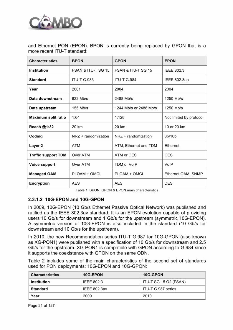
2.3.1.1 BPON, GPON and EPON PON can transmit data using different Layer 2 technologies following different standards. Table 1 reviews some of the main characteristics of the early standards used for PON deployments: Broadband PON (BPON), Gigabit-capable PON (GPON)
Page 21 of 127
and Ethernet PON (EPON). BPON is currently being replaced by GPON that is a more recent ITU-T standard:
Characteristics BPON GPON EPON
Institution FSAN & ITU-T SG 15 FSAN & ITU-T SG 15 IEEE 802.3
Standard ITU-T G.983 ITU-T G.984 IEEE 802.3ah
Year 2001 2004 2004
Data downstream 622 Mb/s 2488 Mb/s 1250 Mb/s
Data upstream 155 Mb/s 1244 Mb/s or 2488 Mb/s 1250 Mb/s
Maximum split ratio 1:64 1:128 Not limited by protocol
Reach @1:32 20 km 20 km 10 or 20 km
Coding NRZ + randomization NRZ + randomization 8b/10b
Layer 2 ATM ATM, Ethernet and TDM Ethernet
Traffic support TDM Over ATM ATM or CES CES
Voice support Over ATM TDM or VoIP VoIP
Managed OAM PLOAM + OMCI PLOAM + OMCI Ethernet OAM, SNMP
Encryption AES AES DES
Table 1: BPON, GPON & EPON main characteristics
2.3.1.2 10G-EPON and 10G-GPON In 2009, 10G-EPON (10 Gb/s Ethernet Passive Optical Network) was published and ratified as the IEEE 802.3av standard. It is an EPON evolution capable of providing users 10 Gb/s for downstream and 1 Gb/s for the upstream (symmetric 10G-EPON). A symmetric version of 10G-EPON is also included in the standard (10 Gb/s for downstream and 10 Gb/s for the upstream). In 2010, the new Recommendation series ITU-T G.987 for 10G-GPON (also known as XG-PON1) were published with a specification of 10 Gb/s for downstream and 2.5 Gb/s for the upstream. XG-PON1 is compatible with GPON according to G.984 since it supports the coexistence with GPON on the same ODN. Table 2 includes some of the main characteristics of the second set of standards used for PON deployments: 10G-EPON and 10G-GPON:
Characteristics 10G-EPON 10G-GPON
Institution IEEE 802.3 ITU-T SG 15 Q2 (FSAN)
Standard IEEE 802.3av ITU-T G.987 series
Year 2009 2010

Page 22 of 127
Upstream speed 1 or 10 Gb/s 2.5 Gb/s
Downstream speed 10 Gb/s 10 Gb/s
Multiplexing method TDMA (up) / TDM (down) TDMA (up) / TDM (down)
Max optical budget loss 29 dB 29 dB to 31 dB (Nominal class)
Maximum split ratio 1:256 1:256 or higher
Reach @1:32 20 km 20 km
Traffic mode Ethernet GEM
Managed OAM Ethernet OAM, SNMP PLOAM + OMCI Table 2: 10G-EPON and 10G-GPON main characteristics
2.3.2 Point to multipoint with logical point to point: WDM-PON The description in this section is restricted to fibre-based infrastructure containing Wavelength-Division Multiplexing (WDM) elements. An early approach for reduced-cost backhaul networks was the so-called passive Wavelength-Division Multiplexing (pWDM), which is an extension of the Black-Link approach as described in ITU-T Recommendation G.695 [4], [5]. Basically, in pWDM, complete WDM systems including transponders / muxponders, management, filters, optional amplifiers and grey client interfaces are replaced by passive filters and coloured pluggable client interfaces. pWDM basically supports Point-to-Point (PtP) connections. However, using active sites with reduced complexity, e.g., local exchanges, the concept can be extended to Point-to-Multipoint (PtMP) connections. This is shown in Figure 7 for a backhaul scenario where a local exchange (Local X) has been partially passivated (it still accommodates a DSL multiplexer). Here, the coloured pluggable interfaces go directly into the Aggregation Switch (AGS) and into the DSL multiplexers.
Figure 7: Concept of passive WDM with coloured interfaces in AGS and DSLAM
pWDM can save CapEx, namely the duplicated grey interfaces which are required for transpondered approaches. As drawbacks, one loses the demarcation between transport and client layer and certain monitoring / supervision functions. Also, optical performance becomes an issue, especially if optical amplifiers are required. As indicated in Figure 7, pWDM typically (but not necessarily) uses two fibres (upstream plus downstream). It also must be noted that today, most host devices (i.e., switches, routers, directors) only accept fixed-wavelength pluggable transceivers (XFP, SFP+) because they cannot perform the tuning task.
Cabinet(VDSL)
Local X(ADSL)
CO
AGS
Page 23 of 127
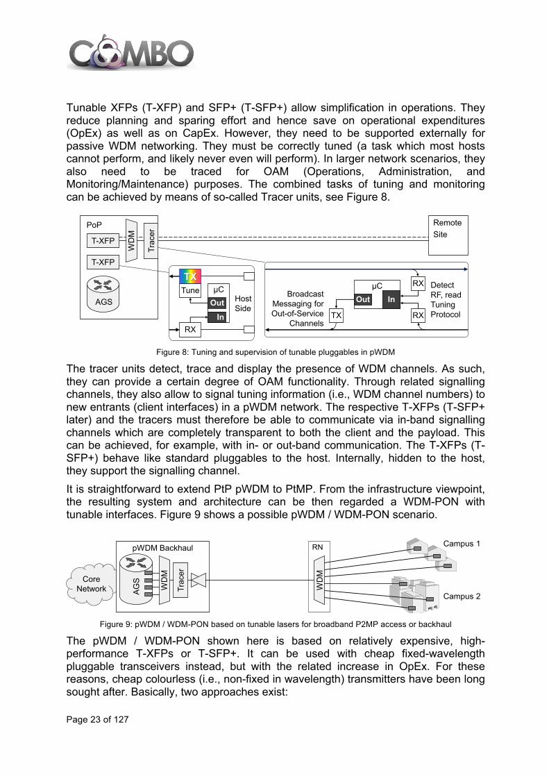
Tunable XFPs (T-XFP) and SFP+ (T-SFP+) allow simplification in operations. They reduce planning and sparing effort and hence save on operational expenditures (OpEx) as well as on CapEx. However, they need to be supported externally for passive WDM networking. They must be correctly tuned (a task which most hosts cannot perform, and likely never even will perform). In larger network scenarios, they also need to be traced for OAM (Operations, Administration, and Monitoring/Maintenance) purposes. The combined tasks of tuning and monitoring can be achieved by means of so-called Tracer units, see Figure 8.
Figure 8: Tuning and supervision of tunable pluggables in pWDM
The tracer units detect, trace and display the presence of WDM channels. As such, they can provide a certain degree of OAM functionality. Through related signalling channels, they also allow to signal tuning information (i.e., WDM channel numbers) to new entrants (client interfaces) in a pWDM network. The respective T-XFPs (T-SFP+ later) and the tracers must therefore be able to communicate via in-band signalling channels which are completely transparent to both the client and the payload. This can be achieved, for example, with in- or out-band communication. The T-XFPs (T-SFP+) behave like standard pluggables to the host. Internally, hidden to the host, they support the signalling channel. It is straightforward to extend PtP pWDM to PtMP. From the infrastructure viewpoint, the resulting system and architecture can be then regarded a WDM-PON with tunable interfaces. Figure 9 shows a possible pWDM / WDM-PON scenario.
Figure 9: pWDM / WDM-PON based on tunable lasers for broadband P2MP access or backhaul
The pWDM / WDM-PON shown here is based on relatively expensive, high-performance T-XFPs or T-SFP+. It can be used with cheap fixed-wavelength pluggable transceivers instead, but with the related increase in OpEx. For these reasons, cheap colourless (i.e., non-fixed in wavelength) transmitters have been long sought after. Basically, two approaches exist:
RemoteSite
PoP
T-XFP
AGS
Trac
er
WD
M
RXTX
µCOut In
RXBroadcast
Messaging for Out-of-Service
Channels
Detect RF, read Tuning Protocol
RX
Tune µCTX
HostSide
Out
In
T-XFP
CoreNetwork W
DM
pWDM Backhaul
AGS
Campus 1
Campus 2
Trac
er
WD
M
RN
Page 24 of 127
• Seeded reflective transmitters • Low(er)-cost tunable laser diodes
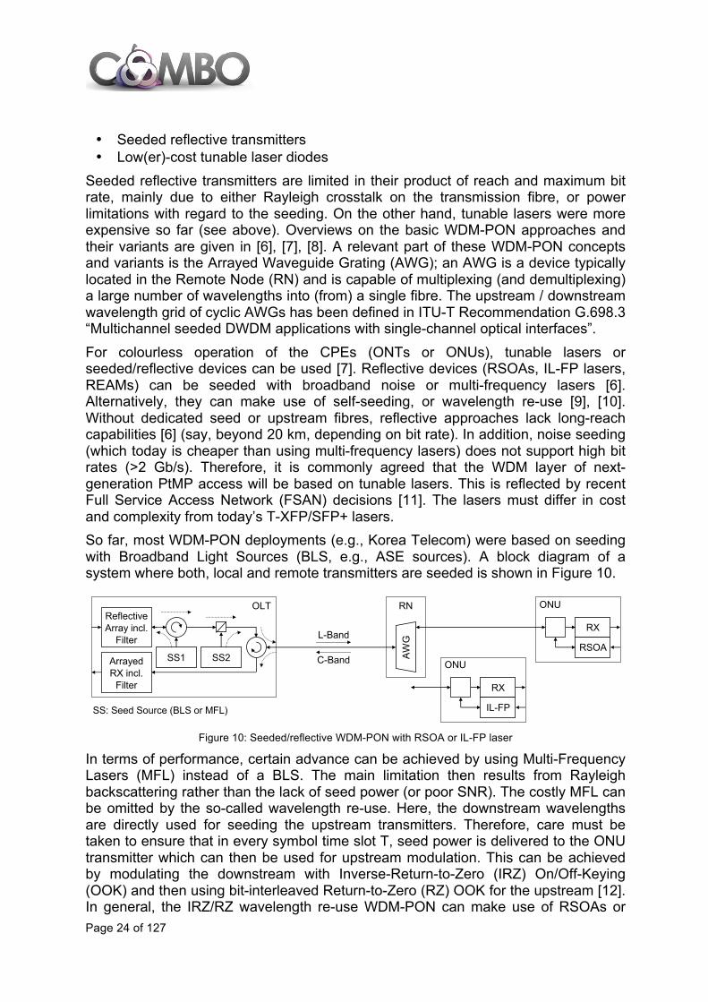
Seeded reflective transmitters are limited in their product of reach and maximum bit rate, mainly due to either Rayleigh crosstalk on the transmission fibre, or power limitations with regard to the seeding. On the other hand, tunable lasers were more expensive so far (see above). Overviews on the basic WDM-PON approaches and their variants are given in [6], [7], [8]. A relevant part of these WDM-PON concepts and variants is the Arrayed Waveguide Grating (AWG); an AWG is a device typically located in the Remote Node (RN) and is capable of multiplexing (and demultiplexing) a large number of wavelengths into (from) a single fibre. The upstream / downstream wavelength grid of cyclic AWGs has been defined in ITU-T Recommendation G.698.3 “Multichannel seeded DWDM applications with single-channel optical interfaces”. For colourless operation of the CPEs (ONTs or ONUs), tunable lasers or seeded/reflective devices can be used [7]. Reflective devices (RSOAs, IL-FP lasers, REAMs) can be seeded with broadband noise or multi-frequency lasers [6]. Alternatively, they can make use of self-seeding, or wavelength re-use [9], [10]. Without dedicated seed or upstream fibres, reflective approaches lack long-reach capabilities [6] (say, beyond 20 km, depending on bit rate). In addition, noise seeding (which today is cheaper than using multi-frequency lasers) does not support high bit rates (>2 Gb/s). Therefore, it is commonly agreed that the WDM layer of next-generation PtMP access will be based on tunable lasers. This is reflected by recent Full Service Access Network (FSAN) decisions [11]. The lasers must differ in cost and complexity from today’s T-XFP/SFP+ lasers. So far, most WDM-PON deployments (e.g., Korea Telecom) were based on seeding with Broadband Light Sources (BLS, e.g., ASE sources). A block diagram of a system where both, local and remote transmitters are seeded is shown in Figure 10.
Figure 10: Seeded/reflective WDM-PON with RSOA or IL-FP laser
In terms of performance, certain advance can be achieved by using Multi-Frequency Lasers (MFL) instead of a BLS. The main limitation then results from Rayleigh backscattering rather than the lack of seed power (or poor SNR). The costly MFL can be omitted by the so-called wavelength re-use. Here, the downstream wavelengths are directly used for seeding the upstream transmitters. Therefore, care must be taken to ensure that in every symbol time slot T, seed power is delivered to the ONU transmitter which can then be used for upstream modulation. This can be achieved by modulating the downstream with Inverse-Return-to-Zero (IRZ) On/Off-Keying (OOK) and then using bit-interleaved Return-to-Zero (RZ) OOK for the upstream [12]. In general, the IRZ/RZ wavelength re-use WDM-PON can make use of RSOAs or
RN ONU
RX
OLT
RSOASS1 SS2
SS: Seed Source (BLS or MFL)
ReflectiveArray incl.
Filter
ArrayedRX incl.
Filter
ONU
RX
IL-FP
AWGL-Band
C-Band
Page 25 of 127
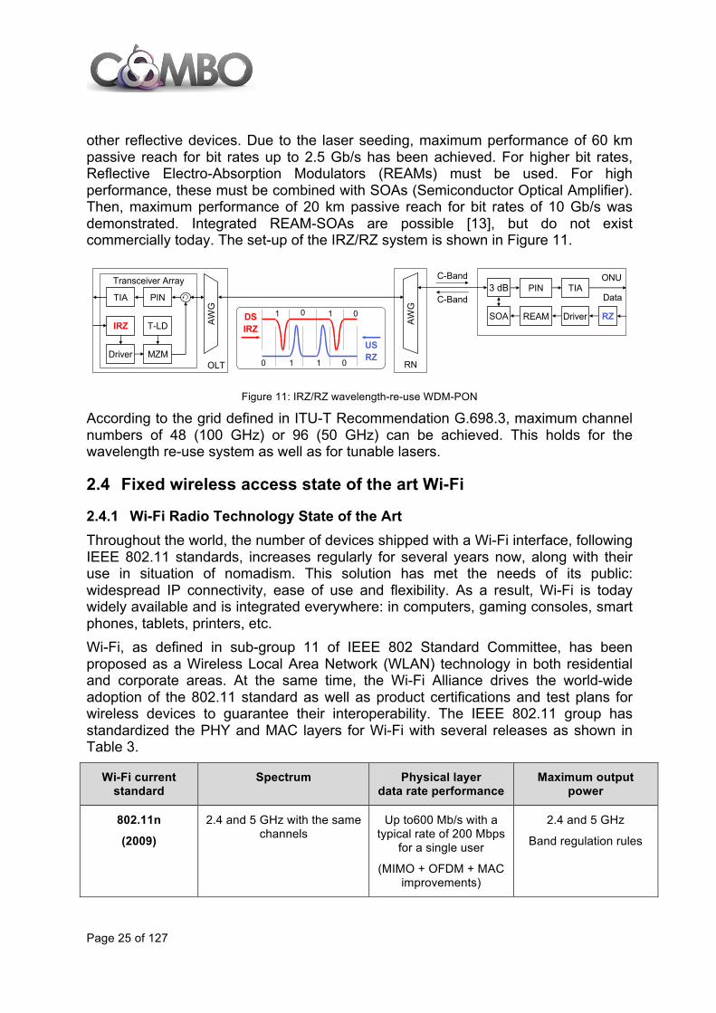
other reflective devices. Due to the laser seeding, maximum performance of 60 km passive reach for bit rates up to 2.5 Gb/s has been achieved. For higher bit rates, Reflective Electro-Absorption Modulators (REAMs) must be used. For high performance, these must be combined with SOAs (Semiconductor Optical Amplifier). Then, maximum performance of 20 km passive reach for bit rates of 10 Gb/s was demonstrated. Integrated REAM-SOAs are possible [13], but do not exist commercially today. The set-up of the IRZ/RZ system is shown in Figure 11.
Figure 11: IRZ/RZ wavelength-re-use WDM-PON
According to the grid defined in ITU-T Recommendation G.698.3, maximum channel numbers of 48 (100 GHz) or 96 (50 GHz) can be achieved. This holds for the wavelength re-use system as well as for tunable lasers.
2.4 Fixed wireless access state of the art Wi-Fi
2.4.1 Wi-Fi Radio Technology State of the Art Throughout the world, the number of devices shipped with a Wi-Fi interface, following IEEE 802.11 standards, increases regularly for several years now, along with their use in situation of nomadism. This solution has met the needs of its public: widespread IP connectivity, ease of use and flexibility. As a result, Wi-Fi is today widely available and is integrated everywhere: in computers, gaming consoles, smart phones, tablets, printers, etc. Wi-Fi, as defined in sub-group 11 of IEEE 802 Standard Committee, has been proposed as a Wireless Local Area Network (WLAN) technology in both residential and corporate areas. At the same time, the Wi-Fi Alliance drives the world-wide adoption of the 802.11 standard as well as product certifications and test plans for wireless devices to guarantee their interoperability. The IEEE 802.11 group has standardized the PHY and MAC layers for Wi-Fi with several releases as shown in Table 3.
Wi-Fi current standard
Spectrum Physical layer data rate performance
Maximum output power
802.11n
(2009)
2.4 and 5 GHz with the same channels
Up to600 Mb/s with a typical rate of 200 Mbps
for a single user
(MIMO + OFDM + MAC improvements)
2.4 and 5 GHz
Band regulation rules
OLT
ONU PIN3 dB
SOA RZDSIRZ
USRZ
0 0
0 01 1
1 1
RN
AW
G
C-Band
C-Band
REAM Driver
TIAData
AW
G
PINTIA
IRZ
Driver MZM
T-LD
Transceiver Array

Page 26 of 127
802.11ac
(2013)
non-contiguous bandwidth at 5GHz divided into 19 channels of 20 MHz.
20/40/80/160 MHz for each channel
Theoretically up to 6.7 Gb/s, with a typical rate of 500 Mb/s for a single
user
Band regulation rules
802.11ad
(2012)
4 channels of 2.16GHz in the 60 GHz band. Certification provided only for channel 2 (worldwide available) from
59.4 to 61.56 GHz
Up to 6,7 Gb/s with a typical rate expected
above 1 Gb/s
Band regulation rules depending on countries
Table 3: Main properties of latest Wi-Fi standards
Since 1999 and the standardization of 802.11a and 802.11b several generations have been completed, the most recent ones being 802.11ac and 802.11ad. It can be observed that Wi-Fi standards have progressively evolved in order to enable higher throughputs. They have always used license-free frequency bands first at 2.4 and 5 GHz, and most recently at 60 GHz with 802.11ad. However, especially the 2.4 GHz band is quite crowded as it is used for other services and presents interference and saturation issues. To pre-empt this, 802.11n amendment takes advantage of the two frequency bands optimizing the allocation of resources depending on the neighbouring Wi-Fi systems. Thus, it can be protected against interferences. 802.11ac has further improved the physical bit-rate thanks to: the possibility to aggregate up to 8 20MHz channels, a more efficient spectral efficiency with a better coding scheme, a unified beamforming and an optimization of spatial diversity and Multi-user MIMO (optional, not implemented yet). Figure 12 represents the channelization of the 2.4 and 5 GHz bands. In the 2.4 GHz band, 13 channels can be exploited, but only 3 non-overlapping 20 MHz bandwidth channels are available. In the 5 GHz band, there are 23 non-overlapping 20 MHz bandwidth channels. However, in each region of the world, local rules limit the number of allowed radio channels.
Figure 12: Channelization of the 2.4 GHz and 5 GHz bands.
Page 27 of 127
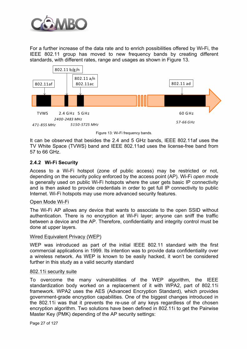
For a further increase of the data rate and to enrich possibilities offered by Wi-Fi, the IEEE 802.11 group has moved to new frequency bands by creating different standards, with different rates, range and usages as shown in Figure 13.
Figure 13: Wi-Fi frequency bands.
It can be observed that besides the 2.4 and 5 GHz bands, IEEE 802.11af uses the TV White Space (TVWS) band and IEEE 802.11ad uses the license-free band from 57 to 66 GHz.
2.4.2 Wi-Fi Security Access to a Wi-Fi hotspot (zone of public access) may be restricted or not, depending on the security policy enforced by the access point (AP). Wi-Fi open mode is generally used on public Wi-Fi hotspots where the user gets basic IP connectivity and is then asked to provide credentials in order to get full IP connectivity to public Internet. Wi-Fi hotspots may use more advanced security features. Open Mode Wi-Fi The Wi-Fi AP allows any device that wants to associate to the open SSID without authentication. There is no encryption at Wi-Fi layer; anyone can sniff the traffic between a device and the AP. Therefore, confidentiality and integrity control must be done at upper layers.
Wired Equivalent Privacy (WEP) WEP was introduced as part of the initial IEEE 802.11 standard with the first commercial applications in 1999. Its intention was to provide data confidentiality over a wireless network. As WEP is known to be easily hacked, it won’t be considered further in this study as a valid security standard
802.11i security suite To overcome the many vulnerabilities of the WEP algorithm, the IEEE standardization body worked on a replacement of it with WPA2, part of 802.11i framework. WPA2 uses the AES (Advanced Encryption Standard), which provides government-grade encryption capabilities. One of the biggest changes introduced in the 802.11i was that it prevents the re-use of any keys regardless of the chosen encryption algorithm. Two solutions have been defined in 802.11i to get the Pairwise Master Key (PMK) depending of the AP security settings:
802.11 b/g/n
802.11 a/n802.11ac802.11af 802.11 ad
2.4 GHz 5 GHz 60 GHzTVWS
471-‐855 MHz2400-‐2483 MHz
5150-‐5725 MHz 57-‐66 GHz
Page 28 of 127
• Pre-shared key (PSK), known as WPA2-PSK WPA2-PSK. WPA2-PSK is used to establish a security network and creates fresh session keys on every association of devices on the Wi-Fi interface. The benefit of WPA2-PSK compared to WEP is that the encryption keys used for each client on the network are unique and specific to each device. Every packet sent over the air is encrypted with a unique key. Data confidentiality and integrity are performed on the Wi-Fi radio layer between the device and the AP. WPA2-PSK offers good security since it avoids key re-use and provides unique and fresh encryption keys to each connected device. This security mode is often used on private residential gateways for broadband Internet access to offer a secured wireless access to the private LAN (home network).
• After 802.1X authentication, known as WPA2-Enterprise This security standard relies on Extensible Authentication Protocol (EAP) over IEEE 802, known as "EAP over LAN" or EAPOL has been defined to offer a framework for authenticating and controlling user traffic to a protected network. EAPOL standard specifies the way EAP frames are passed over a wired or wireless LAN. In the wireless environment, it describes a way for the AP and the wireless user to share and change encryption keys. WPA2-Enterprise will first authenticate the user with one EAP method to generate one dedicated top key, called the Master Session Key (MSK). This key is used to derive the Pairwise Master Key (PMK), one per device, unlike WPA2-PSK, which uses the same PMK for all devices of the LAN. Extensible Authentication Protocol over LAN (EAPOL) port control (802.1X) involves three functional elements: - A Supplicant: a requesting device that wishes to attach to the LAN/WLAN. - An Authenticator: the Wi-Fi AP. The Wi-Fi AP (Authenticator) acts as a
security guard to a protected network. - An Authentication, Authorization, and Accounting (AAA) Server supporting
RADIUS or Diameter and EAP protocols. When EAP-SIM or EAP-AKA methods are used, the AAA server is interfaced with a Home Location register (HLR) via Mobile Application Part (MAP) or Home Subscriber Server (HSS) via Diameter protocols. The Wi-Fi device (as supplicant) is not allowed to access through the AP (as authenticator) to the protected side of the network until the device identity has been validated and authorized. The AP (authenticator) forwards the credentials to the authentication server for verification. If the authentication server (AAA) determines that the credentials are valid, the device is allowed to access resources located on the protected side of the network. This authorization is performed on Layer 2 (MAC address-based authorization).
WPA2-enterprise security mode was primarily used on private corporate Wi-Fi networks and is now considered for public Wi-Fi hotspots, to allow mobile (SIM/USIM enabled) devices to get IP connectivity over a Wi-Fi access network in a “seamless” way, using their SIM/USIM identity.

Page 29 of 127
Figure 14: 802.1X port controlled mechanism
• Wi-Fi Protected Setup (WPS) WPS is a standard designed to ease the task of setting up and configuring security on WLANs. It was created by the Wi-Fi Alliance and comes with a certification program that has certified about 2400 devices by the end of 2011 (source: Wi-Fi Alliance and ABI Research Group). WPS consists of a sequence of EAP message exchanges that is triggered by a user action (PIN verification, Push-button method, Near Field Communication, USB data transfer). WPS pairing between a Wi-Fi device and a Wi-Fi AP is well-suited for residential use (with PIN or Push-button options). With an increasing penetration of NFC enabled devices, it becomes also a convenient and user-friendly access control method for public Wi-Fi hotspots.
2.4.3 Wi-Fi technology as access network Functional entities The common Wi-Fi public architectures are usually based on the main following functional entities:
• Access Point: in charge of the users’ Wi-Fi connection. • Wi-Fi Edge: the router that manages the users’ IP traffic: filtering, Hypertext
Transfer Protocol (HTTP) redirection, rate limiting, Network Address Translation/ Network Address and Port Translation (NAT/NAPT), etc.
• Web Portal: a web server where the user is redirected to provide its credentials, accept the terms of use of the service and/or purchase some credits for the service.
• AAA server: usually a Remote Access Dial In User Service (RADIUS) server that enables authentication, authorization and accounting of the users.
Some other entities may also be required depending on the Wi-Fi operator deployment choices:
• IP address allocation server: usually a Dynamic Host Configuration Protocol (DHCP) server that may be collocated with the Wi-Fi Edge.
Page 30 of 127
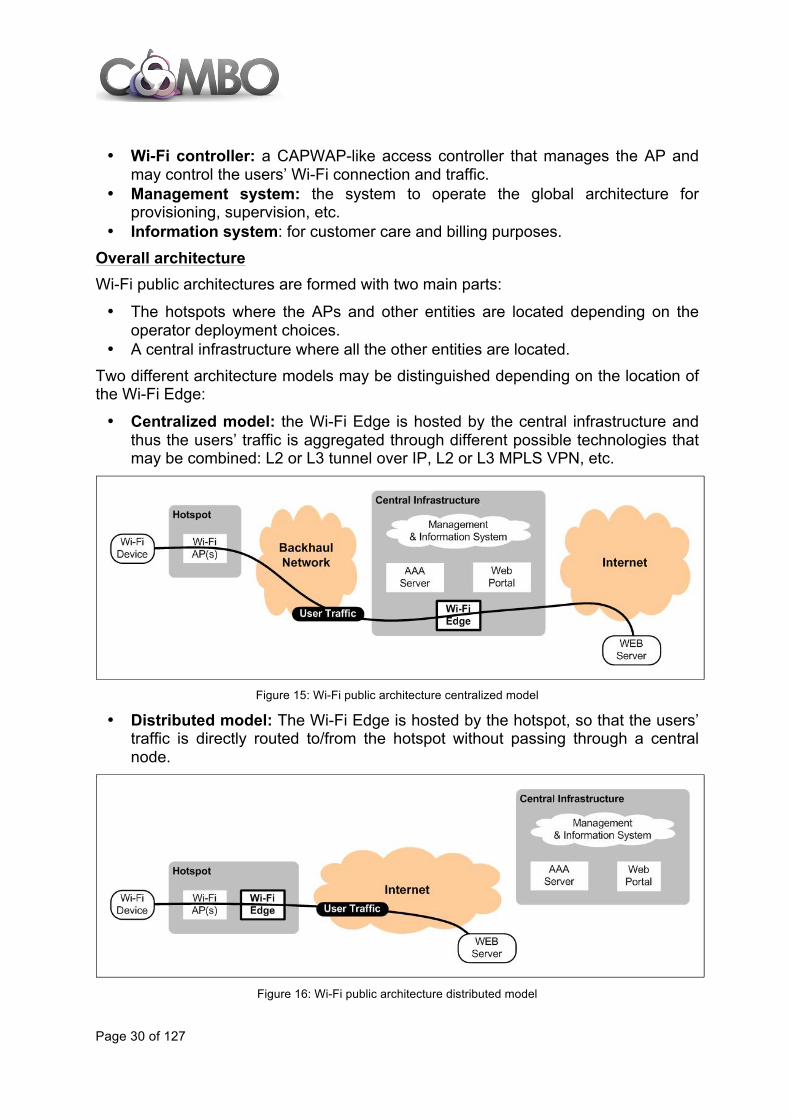
• Wi-Fi controller: a CAPWAP-like access controller that manages the AP and may control the users’ Wi-Fi connection and traffic.
• Management system: the system to operate the global architecture for provisioning, supervision, etc.
• Information system: for customer care and billing purposes. Overall architecture Wi-Fi public architectures are formed with two main parts:
• The hotspots where the APs and other entities are located depending on the operator deployment choices.
• A central infrastructure where all the other entities are located. Two different architecture models may be distinguished depending on the location of the Wi-Fi Edge:
• Centralized model: the Wi-Fi Edge is hosted by the central infrastructure and thus the users’ traffic is aggregated through different possible technologies that may be combined: L2 or L3 tunnel over IP, L2 or L3 MPLS VPN, etc.
Figure 15: Wi-Fi public architecture centralized model
• Distributed model: The Wi-Fi Edge is hosted by the hotspot, so that the users’ traffic is directly routed to/from the hotspot without passing through a central node.
Figure 16: Wi-Fi public architecture distributed model
Page 31 of 127
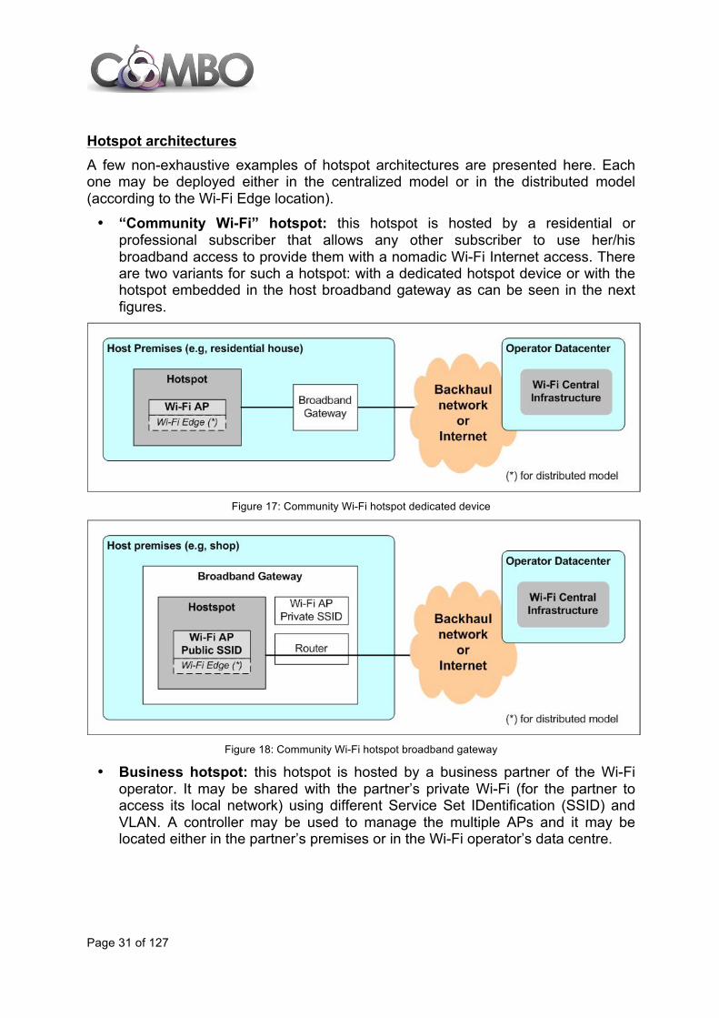
Hotspot architectures A few non-exhaustive examples of hotspot architectures are presented here. Each one may be deployed either in the centralized model or in the distributed model (according to the Wi-Fi Edge location).
• “Community Wi-Fi” hotspot: this hotspot is hosted by a residential or professional subscriber that allows any other subscriber to use her/his broadband access to provide them with a nomadic Wi-Fi Internet access. There are two variants for such a hotspot: with a dedicated hotspot device or with the hotspot embedded in the host broadband gateway as can be seen in the next figures.
Figure 17: Community Wi-Fi hotspot dedicated device
Figure 18: Community Wi-Fi hotspot broadband gateway
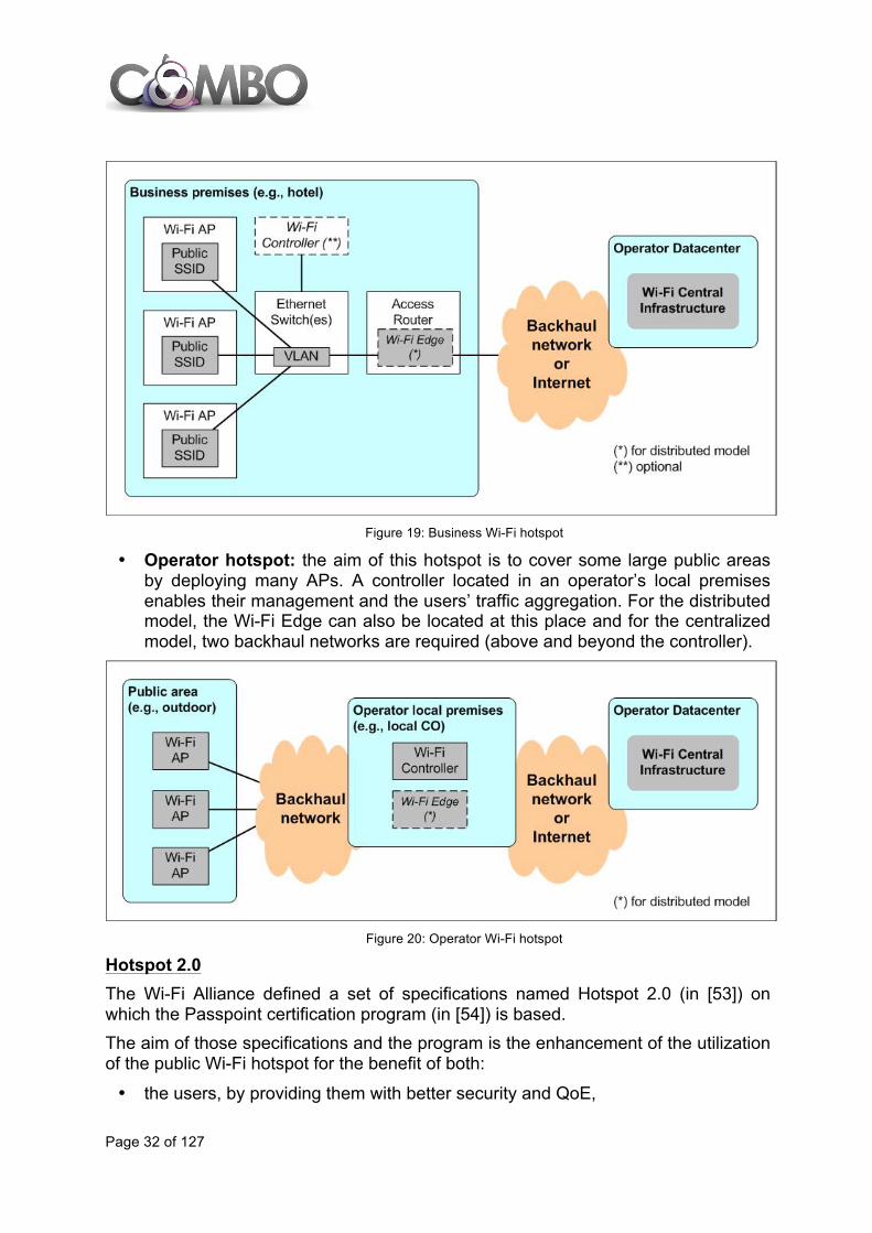
• Business hotspot: this hotspot is hosted by a business partner of the Wi-Fi operator. It may be shared with the partner’s private Wi-Fi (for the partner to access its local network) using different Service Set IDentification (SSID) and VLAN. A controller may be used to manage the multiple APs and it may be located either in the partner’s premises or in the Wi-Fi operator’s data centre.
Page 32 of 127
Figure 19: Business Wi-Fi hotspot
• Operator hotspot: the aim of this hotspot is to cover some large public areas by deploying many APs. A controller located in an operator’s local premises enables their management and the users’ traffic aggregation. For the distributed model, the Wi-Fi Edge can also be located at this place and for the centralized model, two backhaul networks are required (above and beyond the controller).
Figure 20: Operator Wi-Fi hotspot
Hotspot 2.0 The Wi-Fi Alliance defined a set of specifications named Hotspot 2.0 (in [53]) on which the Passpoint certification program (in [54]) is based. The aim of those specifications and the program is the enhancement of the utilization of the public Wi-Fi hotspot for the benefit of both:
• the users, by providing them with better security and QoE,

Page 33 of 127
• and network operators, by enabling the mobile customers traffic to be more easily offloaded on Wi-Fi network (thus optimizing Wi-Fi and mobile operator networks).
The documents were published end of 2012 and provide the following features:
• Network discovery and selection. The devices rely on IEEE 802.11u Access Network Query Protocol (ANQP) to identify and associate with Passpoint networks in the background, without any active intervention from the subscriber.
• Seamless and secure network access. The authentication no longer requires a browser-based sign-on or the subscriber to enter a password, but devices are automatically authenticated, using 802.1X to convey an Extensible Authentication Protocol method based either on a Subscriber Identity Module (EAP-SIM/AKA/AKA’) or some certificates (EAP-TLS/TTLS).
• Secure connectivity. All connections are secured with the IEEE 802.11i Counter-Mode/CBC-Mac Protocol (CCMP), thus providing a level of security comparable to cellular networks.
2.5 Microwave Today, microwave links typically operate at carrier frequencies between 6 and 86 GHz. One of the more common applications is mobile backhauling, which is usually connected through fibre, microwave, or copper at the physical layer. As illustrated in Figure 21, the most common options are fibre and microwave, representing 50% and 42%, respectively, of all backhaul deployments in the world by the end of 2012. Looking ahead, it is expected that fibre and microwave will remain attractive choices for backhaul, whereas the use of copper will continue to decrease [15].
Figure 21: Backhaul physical medium, from [15]
Compared to the wired fibre and copper, the advantages of microwave technology are fast deployment, total low cost, and flexibility because of its wireless nature. This

Page 34 of 127
makes microwave the best option to use where there is no existing fibre and deploying it dedicated to backhauling only will be too costly. The deployment and use of microwave links in Europe are regulated through ETSI documents where the two most important recommendations are:
• Antennas characteristics: ETSI EN 302 217-4-2 Fixed Radio Systems; Characteristics and requirements for point-to-point equipment and antennas. Part 4-2: Antennas
• Fixed point-to-point links regulation: ETSI EN 302 217-3 Fixed Radio Systems; Characteristics and requirements for point-to-point equipment and antennas. Part 3: Equipment operating in frequency bands where both frequency coordinated or uncoordinated deployment might be applied.
The microwave spectrum is a valuable finite resource that has been identified as a potential bottleneck for mobile broadband backhaul networks. Today, the majority of PtP microwave links are installed in frequency bands at 6-38 GHz. When these bands were introduced, the need for wide channel bandwidths was limited so these bands were populated mostly with narrow channels. However, because of the success of mobile broadband and, as a consequence, higher capacity requirements, the need for narrow channels has decreased and the trend goes towards using wider channels. In Europe, the most common channel bandwidths are 3.5 MHz, 7 MHz, 14 MHz and 28 MHz, with 56 MHz and 112 MHz available in some places. The decreased use of narrow 3.5 MHz channels allows regulators to re-farm the bands below 40 GHz to provide wide 112 MHz channels [16]. At the same time, regulators use price strategies to encourage more efficient use of existing frequency bands and channel bandwidths to avoid congestion in the microwave spectrum. Microwave technology has undergone a tremendous evolution over the last decade with new frequency bands, architectures, and antenna concepts made available. In the beginning of 2000, a legacy microwave link on a 28 MHz channel encoding 2 bits per symbol typically reached 37 Mb/s, corresponding to a spectral efficiency of 1.3 b/s/Hz. Spectral shaping of the signal at the transmitter increased the spectral efficiency to approximately 1.8 b/s/Hz, and a continuous increase of the modulation order, from 2 to 10 bits per symbol, increased the spectral efficiency five times to approximately 9 b/s/Hz. Polarization multiplexing doubles the efficiency to 18 b/s/Hz and spatial multiplexing using a 2x2 line-of-sight (LOS) MIMO system again would double the efficiency to approximately 36 b/s/Hz [16]. In modern microwave systems, the symbol rate may reach up to 90% of the channel bandwidth without violating spectrum masks. For example, given 56 MHz channel bandwidth, the symbol rate can reach up to 50 MBaud. Given 56 MHz bandwidth and using 256-QAM, a modern microwave system can reach up to 56 MHz x 0.9 x log2(256) bits/symbol = 400 Mb/s on a single carrier. Similarly, using 1024-QAM would result in 10 bits/symbol and data rates up to 500 Mb/s on a single carrier. However, the cost of higher-order modulation is, in practice, increased complexity and overhead. The net spectral efficiency gain decreases when increasing the modulation order. For example, while an increase from 2-QAM to 4-QAM doubles the
Page 35 of 127
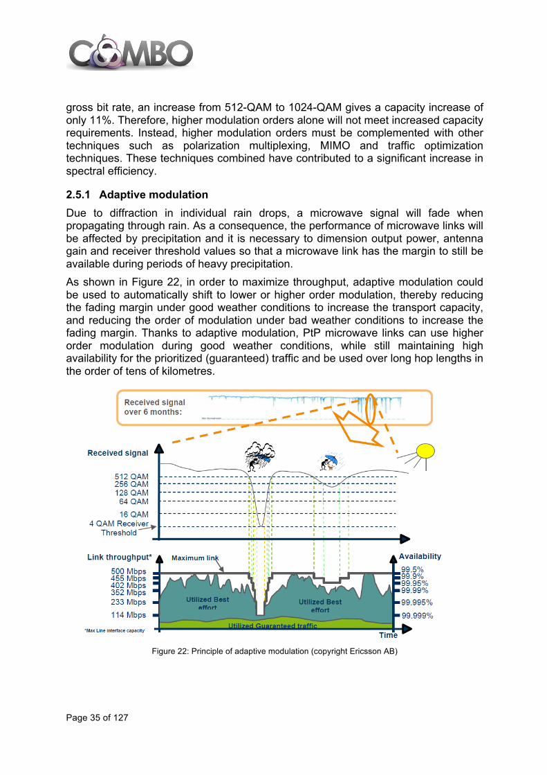
gross bit rate, an increase from 512-QAM to 1024-QAM gives a capacity increase of only 11%. Therefore, higher modulation orders alone will not meet increased capacity requirements. Instead, higher modulation orders must be complemented with other techniques such as polarization multiplexing, MIMO and traffic optimization techniques. These techniques combined have contributed to a significant increase in spectral efficiency.
2.5.1 Adaptive modulation Due to diffraction in individual rain drops, a microwave signal will fade when propagating through rain. As a consequence, the performance of microwave links will be affected by precipitation and it is necessary to dimension output power, antenna gain and receiver threshold values so that a microwave link has the margin to still be available during periods of heavy precipitation. As shown in Figure 22, in order to maximize throughput, adaptive modulation could be used to automatically shift to lower or higher order modulation, thereby reducing the fading margin under good weather conditions to increase the transport capacity, and reducing the order of modulation under bad weather conditions to increase the fading margin. Thanks to adaptive modulation, PtP microwave links can use higher order modulation during good weather conditions, while still maintaining high availability for the prioritized (guaranteed) traffic and be used over long hop lengths in the order of tens of kilometres.
Figure 22: Principle of adaptive modulation (copyright Ericsson AB)

Page 36 of 127
2.5.2 Millimetre-wave transmission The frequency bands at 60 GHz and above are commonly referred to as the millimetre-wave (mm-wave) bands. For fixed service applications, the interesting bands today are, typically, the partly unlicensed 60 GHz band (57-66GHz) and the E-band (71-76 GHz, 81-86 GHz, and 92-95 GHz). The mm-wave bands have several advantages compared to lower frequency bands. First, due to the short wavelengths, it is possible to create small and compact antennas with high gain, which is advantageous for the deployment of future dense networks. Another advantage is the availability of wide channel bandwidths. In the 60 GHz band, 50 MHz channels are available and in the E-band, 250 MHz up to 1 GHz channels could be allocated. The wider channels make it possible to support Gb/s links. When the E-band was first introduced in the beginning of 2000, the high available bandwidth triggered the use of high capacity but less spectral efficient solutions. However, a current trend within the industry is to use the available bandwidth more responsibly, improving spectral efficiency and thereby using the already owned spectra in a more efficient way and, as a consequence, reducing cost of ownership. On a longer term this will enable more users to take advantage of the available spectra. Currently, there is an ongoing discussion in ETSI on whether the minimum channel bandwidth in the E-band should be reduced to 62.5 MHz in order to take advantage of available, already developed, spectrally efficient baseband hardware. It is also worth mentioning that the high path attenuation in the 60 GHz band, due to the oxygen resonance peak at 60 GHz, is beneficial for short range transmission applications such as small cell backhaul, increasing the frequency reuse factor. Figure 23 shows the relationship between channel bandwidth, spectral efficiency and throughput. Using a wide 1 GHz channel bandwidth with 4-QAM modulation would support Gb/s throughput. Consequently, increasing the spectral efficiency for a 1 GHz channel from 1 b/s/Hz to 36 b/s/Hz (as discussed previously for lower frequencies) would result in 36 Gb/s net throughput. These high data rates are similar to capacity figures previously only considered for optical networks.
Figure 23: Throughput versus channel bandwidth (copyright Ericsson AB)
Page 37 of 127
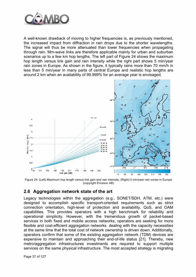
A well-known drawback of moving to higher frequencies is, as previously mentioned, the increased impact from diffraction in rain drops due to the shorter wavelengths. The signal will thus be more attenuated than lower frequencies when propagating through rain. Mm-wave links are therefore applicable mainly for urban and suburban scenarios up to a few km hop lengths. The left part of Figure 24 shows the maximum hop length versus link gain and rain intensity while the right part shows 5 min/year rain zones in Europe. As shown in the figure, it typically rains more than 70 mm/h in less than 5 min/year in many parts of central Europe and realistic hop lengths are around 2 km when an availability of 99.999% for an average year is envisaged.
Figure 24: (Left) Maximum hop length versus link gain and rain intensity; (Right) 5 min/year rain zones in Europe
(copyright Ericsson AB)
2.6 Aggregation network state of the art Legacy technologies within the aggregation (e.g., SONET/SDH, ATM, etc.) were designed to accomplish specific transport-oriented requirements such as strict connection orientation, high-level of protection and availability, QoS, and OAM capabilities. This provides operators with a high benchmark for reliability and operational simplicity. However, with the tremendous growth of packet-based services in both fixed and mobile access networks, operators are seeking for more flexible and cost-efficient aggregation networks dealing with the capacity necessities at the same time that the total cost of network ownership is driven down. Additionally, operators confirm that some of the existing aggregation network (TDM) devices are expensive to maintain and approaching their end-of-life status [21]. Thereby, new metro/aggregation infrastructures investments are required to support multiple services on the same physical infrastructure. The most accepted strategy is migrating
Page 38 of 127
aggregation networks towards the consolidation of Optical, Carrier Ethernet, WDM, IP/MPLS technologies and packet transport (MPLS-TP), without compromising the carrier-graded virtues of legacy technologies (i.e., control, resilience, OAM, scalability, etc.).
2.6.1 SONET/SDH Transport Synchronous Optical Networking/Synchronous Digital Hierarchy (SONET/SDH) has historically supported the transport burden in both metro/aggregation and core networks. It was optimized for transporting constant bit rate voice traffic and is not efficient for transport of burst data traffic. Since most incumbent operators have a large deployment based on SONET/SDH networks, such operators had the strong desire of preserving the existing TDM infrastructure to maintain the revenue streams (e.g., voice, leased lines). Therefore, operators are forced to explore alternatives to improve SONET/SDH standards aiming at relaxing the bandwidth-efficiency and scalability concerns of older legacy TDM systems [22]. In other words, the aim was to upgrade SONET/SDH technology to more optimally and efficiently accommodate the transport of ubiquitous Ethernet services. Such an improvement is widely termed as next-generation SONET/SDH (NGS). These technologies include Generic Framing Procedure (GFP), Virtual Concatenation (VCAT), inverse multiplexing, and Link Capacity Adjustment Scheme (LCAS). One of the main benefits of NGS is that it is backward compatible with legacy SONET/SDH as well as ITU-T Optical Transport Network (OTN) standards. Despite the efforts done on NGS to make SONET/SDH a more bandwidth-flexible technology, among the operators, the general consensus is to base the deployment of the future aggregation networks on Ethernet technology which natively fits to customers premises using more and more the Ethernet protocol.
2.6.2 Carrier-Grade Ethernet Services Nowadays, IP is the dominant data protocol used by any applications and being well adapted to be carried over Ethernet frames. Specifically, Ethernet, being a variable-length frame-based technology, efficiently carries IP traffic and has acted as the first aggregation level for IP networks. The cost-efficiency of Ethernet interfaces does make this technology a credible alternative to constitute the convergence solution for packet transport networks within both aggregation and core networks. To this end, different enhancements have been done to evolve Ethernet towards a more scalable and carrier-class technology [23], [27]:
• IEEE 802.1Q: Virtual LANs (VLANs) • IEEE 802.1AD: Provider Bridges (Q-in-Q) • IEEE 802.1ah: Provider Backbone Bridging (MAC-in-MAC) • IEEE 802.1Qay: Provider Backbone Bridging – Traffic Engineering (PBB-
TE/PBT) The most critical success factor to consider carrier-grade Ethernet as a transport solution is the efficient Service Level Agreement (SLA) support. Therefore, the challenge is to maintain Ethernet as simple as possible while becoming an SLA-driven carrier-grade technology. To this end, Ethernet must evolve to display the

Page 39 of 127
same properties as current metro and core transport technologies (e.g., SONET/SDH) [24], namely scalability, traffic prioritization, OAM, security and resilience. Meaningful examples of this evolution are:
• ITU-T G.8013/Y.1731: OAM functions and mechanisms for Ethernet based networks
• ITU-T G.8031/Y.1342: Ethernet linear protection switching • ITU-T G.8032/Y.1344: Ethernet ring protection switching
To deal with the above properties the Metro Ethernet Forum (MEF) [25] was founded. MEF is a global industry alliance whose main purpose is to develop technical specifications and implementation agreements to promote the interoperability and deployment of Carrier Ethernet worldwide. The primary priorities of the MEF are: to define Ethernet services for metro/aggregation networks and to define carrier-grade Ethernet-based transport technologies.
2.6.3 Ethernet service over MPLS, MPLS-TP and S-MPLS MPLS is a highly scalable packet forwarding technology supporting QoS, traffic engineering and fast failure recovery. Using pseudowire (PW), IP/MPLS supports wire emulation for carrying different services other than IP traffic such as ATM, TDM, SONET/SDH and Ethernet over packet-switched networks. This enables MPLS to be a candidate technology within the aggregation network to support multiple services. Specifically, for Ethernet traffic, point-to-point services are emulated using Virtual Private Wire Service (VPWS) [28]. That is, point-to-point MPLS Label Switched Paths (LSPs) are set up between a pair of Label Switched Routers (LSRs) to carry Ethernet PWs. Multiple PWs can be carried over a single LSP having its own class of service. Virtual Private LAN Service (VPLS) [29], [30] allows Ethernet multipoint-to-multipoint service over MPLS networks. Aiming at leveraging benefits of MPLS (e.g., scalability, statistical multiplexing, etc.), MPLS-TP was (and is being) defined to enable MPLS to be deployed in a transport network and operated similarly as existing transport technologies. MPLS-TP (jointly being defined by ITU-T and IETF) [31] represents a set of recommendations about how to design an MPLS network with a transport profile. MPLS-TP is defined as a profile leveraging and building upon MPLS forwarding, PW and dynamic Generalized Multi-Protocol Label Switching (GMPLS) control plane technology (optional in the MPLS-TP standard). Furthermore, it is extended to support in-band active and reactive OAM enhancements, deterministic path protection and network management-based static provisioning equivalent to legacy transport technologies such as SONET/SH. Recently, MPLS is considered by both vendors and network operators as feasible network architecture to provide the required capabilities for integrating core, aggregation and access networks within a single domain. This is referred to as seamless MPLS [32], or simply S-MPLS. Therefore, S-MPLS eliminates the interface among network equipment at each layer of the MPLS infrastructure. By doing so, network operators have a single control plane reducing the operational cost. Nevertheless, the main benefit is that S-MPLS provides end-to-end service delivery at any point regardless of the transport. Consequently, S-MPLS is a suitable

Page 40 of 127
transport solution to be adopted by different services: residential, mobile backhaul, business, etc.
2.6.4 Wavelength Switched Optical Networks Wavelength Switched Optical Networks (WSONs) are constituted of subsystems that include WDM links, tunable transmitter and receivers, ROADMs, wavelength converters, and electro-optical network elements. A WSON is a WDM-based optical network where switching is performed based on the centre wavelength of an optical signal. In general, WSON has been deployed within core networks leveraging their coarse high transport capacity and long reach. Nevertheless, due to the continuous growth of the capacity demand, WDM technology is being adopted within aggregation networks (Figure 25). The deployment of WDM systems in metro networks enhances the scalability as well as the capacity efficiency of Ethernet traffic transport.
Figure 25: Deployment of WDM networks within aggregation / metro segments.
Last but not least, aiming at attaining a more efficient aggregation level as well as reducing the CapEx, an appealing solution that has already begun relies on a multi-layer network approach which combines both packet-switching (performing aggregation) and optical switching (providing transport capacity). This multi-layer approach leverages the best of both IP and WDM worlds using transport enablers such as Carrier Ethernet, MPLS, MPLS-TP and/or OTN [130] By doing so, massive scalability within the aggregation networks can be achieved where packet transport (e.g., MPLS-TP) / Carrier Ethernet technologies allow grooming multiple Ethernet services from the access networks by exploiting statistical multiplexing. Then, these bandwidth-flexible packet connections may be routed within the optical domain over end-to-end wavelength services. This provides packets offload towards the optical layer [131] (also referred to as optical bypass). Consequently, cost reductions are achieved thanks to the reduction of the packet switching equipment size (e.g., IP routers). Furthermore, significant energy consumption reduction can be achieved as well due to the reduction of the electronic packet ports [130].
eNodeB
Backbone
Internet
Business (Corporate Network)
Residential
Access Aggregation Core
Packet-‐switching (MPLS-‐TP) nodeOptical-‐switching (WSON) node
Edge Node
Core Node
Page 41 of 127
During the last decade, it has been discussed the necessity, design and deployment of a common (unified) control plane to enable a tight cooperation of both packet and optical switching layers and thus fully exploit the targeted multi-layer advantages. However, despite the effort, the actual deployment in the operation networks of a unified control plane has barely happened. The main problem is that networks are composed of heterogeneous network equipment where the corresponding vendors (packet and optical switches) deploy their own control entities including proprietary protocols. This severally complicates the use of a unified control plane [130]. In light of this, both layers are controlled independently relying on an overlay control approach. This overlay approach restricts the control interaction and cooperation between different layers, and thus, not fully exploits the benefits associated to the multi-layer network infrastructure. To overcome these multi-layer interworking issues, some efforts are being done in the context of the multi-layer Path Computation Element (PCE) [86]. The PCE is a route computation entity being capable to harmonize the two technologies and facilitate their network interworking. Another promising architecture to deploy effective multi-layer control is the adoption of logically centralized SDN control. The SDN controller is provided with a global view of the resources (packet and optical) which facilitates the optimization of both layers and their interworking [131]. Further details about SDN and PCE control solutions are discussed in section 4.8.2.
Page 42 of 127
3 STATE OF THE ART OF MOBILE NETWORKS This section covers the main systems and innovations in mobile communications that have been used in commercial deployments in the last twenty years or are part of a finalized standard. It begins with 2G systems (that are still used today), continues with 3G and finalizes with LTE. Additionally, the last section of this chapter includes current mobile backhaul alternatives.
3.1 2G 2G or the second generation of mobile systems is not a standard or protocol itself but a way to change mobile telephony protocols from analogue to digital, and it represents all families of standards and systems of digital mobile communication. The two main 2G systems industries, in the U.S. and Europe, developed many standards. Some of the most relevant were GSM (Global System for Mobile Communications), Cellular PCS/IS-136, ITU IS-95, D-AMPS (Digital Advanced Mobile Phone System) and PHS (Personal Handyphone System), being GSM mainly used in Europe. The GSM network is composed of the Base Station Subsystem (BSS) and the Network Switching Subsystem (NSS). The BSS is responsible for handling traffic and signalling between a mobile phone and the NSS. In the BSS, the Base Transceiver Station (BTS) contains the equipment for transmitting and receiving radio signals (transceivers), antennas, and equipment for encrypting and decrypting communications with the Base Station Controller (BSC). The BSC provides the intelligence behind the BTSs, it handles transfers, CDMA frequency hopping and basically it acts as a traffic hub. In the NSS, the MSC (Mobile Services Switching Centre) takes care of switching tasks within the network and provides connection to other networks like PSTN (Public Switched Telephone Network) or ISDN (Integrated Services Digital Network). The major evolution in 2G, sometimes called 2.5G, was the General Packet Radio Services (GPRS). GPRS was an important development for packet exchange services, where a certain QoS is guaranteed during the connection. Two new nodes and a new backbone IP network are added for the data transmission through GPRS. These two new nodes are the GGSN (Gateway GPRS Support Node), which is a node that connects the GPRS network to external IP networks such as the internet, and the SGSN (Serving GPRS Support Node), responsible for interacting with the radio interface and storing the location information in the radio interface of GPRS subscribers. The latest evolution of GSM is called Enhanced Data rates for GSM Evolution (EDGE). EDGE delivers higher bit rates per radio channel (theoretical maximum is 473.6 kb/s for 8 timeslots), resulting in a threefold increase in capacity and performance compared to an ordinary GSM/GPRS connection.
3.2 3G 3G is short for third-generation voice and data transmission via mobile systems. 3G provides higher speeds of up to 28 Mb/s (although in practice average data rates in

Page 43 of 127
commercial networks are around 3 Mb/s), better sound quality and reception than GPRS, and it allows users to stay connected with a permanent internet access. In 1999, 3G was defined by the IMT-2000 process, and ITU approved five radio interfaces for IMT-2000 as part of the ITU-R M.1457. This process did not standardize any technology but imposed a set of requirements such as 2 Mb/s data rate for indoor, 384 kb/s for outdoor and 144 kb/s for vehicular environments. Today, the idea of a single international standard has been divided into multiple standards all with their own technical characteristics (frequency range of the spectrum and multiplexing technologies, mainly). The selected technologies were: Wideband CDMA (W-CDMA), CDMA2000 (an evolution of CDMA IS-95), Time Division and Time Division Synchronous CDMA (TD-CDMA and TD-SCDMA), UWC-136 (an evolution of IS-95) and DECT. W-CDMA is part of a broader specification known as Universal Mobile Telecommunication System (UMTS). W-CDMA has two basic modes of operation: Frequency Division Duplex (FDD) and Time Division Duplex (TDD), and it is a new air interface access method that requires a new Radio Access Network (RAN) called UMTS Terrestrial RAN (UTRAN). It consists of a number of Radio Network Subsystems (RNS) which are the main communication nodes of the UMTS network. An RNS is responsible for the resource allocation and the transmission/reception in a set of cells. Each RNS is controlled by a Radio Network Controller (RNC), and the RNC connects to one or more NodeB elements. The NodeBs are the elements of the network that correspond to the base stations. The RNC is responsible for controlling all the logical resources of a set of NodeBs. 3GPP is the organization that has continued developing the mobile systems under the scope of the IMT-2000. 3GPP has defined the UMTS evolution through different releases which are considered High Speed Packet Access (HSPA) services, introducing new features in each of them. The UMTS specification was defined in Release 99, however other releases were published later, such as Releases 5, 6 and 7.
3.3 LTE Long Term Evolution (LTE) was the following wireless communication standard developed in 2008 by the 3GPP and is specified in its Release 8 document series. The main motivations for LTE were:
• Need to ensure the continuity of competitiveness of the 3G system for the future.
• User demand for higher data rates and quality of service. • A Packet Switch optimised system. • Continued demand for cost reduction (CapEx and OpEx). • Low complexity.
Thus, main requirements for LTE are:
• High spectral efficiency and high peak data rates that allow 100 Mb/s for downlink and 50 Mb/s for uplink within 20 MHz bandwidth.
Page 44 of 127
• Improved spectrum efficiency (up to 5 b/s/Hz). • Cell range between 5 km (optimal size) and 100 km. • Cell capacity up to 200 active users per cell (5 MHz bandwidth). • Mobility optimized for low speed (up to 15 km/h) but supports high speed. • Latency for the user plane is less than 5 ms and less than 50 ms for the
control plane. • Improved broadcasting through Enhanced Multimedia Broadcast Multicast
Service (eMBMS). • Reduced network complexity with flat architecture (less nodes) and full IP
based interfaces. • Scalable bandwidth with 1.4 MHz, 3 MHz, 5 MHz, 10 MHz, 15 MHz and 20
MHz. • Co-existence and compliancy with legacy standards.
In terms of data services, all IP services can be offered through LTE, with enhanced user-experience. The main improvement is related to the “always-on” capability, as the idle-to-active time becomes transparent for the end user (100 ms), higher data rates and low control plane and user plane latency will enhance the user experience for all types of services such as video streaming, web browsing, email, etc. Low latency also allows the introduction of on-line gaming. The first version of LTE has been officially completed in March 2009, Release 9 was completed in March 2010 and included enhancements and “left-overs” from Release 8 such as eMBMS, full Femto cell support, enhanced voice support (emergency service) and additional self-organizing features. Regarding the functional architecture, Evolved Packet System (EPS) is the LTE global mobile system and is composed of:
• An access part composed of the User Equipment (UE) completed by the Evolved Universal Terrestrial Access Network (E-UTRAN).
• A Core Network part called Evolved Packet Core (EPC). Note: System Architecture Evolution (SAE) is the 3GPP “work item” that aims to define EPC specifications and LTE is the 3GPP “work item” that aims to define radio access technologies and E-UTRAN.
The main components of the EPS architecture consist of the following functional elements:
• The eNodeB (eNB), which handles all radio interface-related functions. • The Mobility Management Equipment (MME), which handles control plane,
mobility, User Equipment (UE) identity, and security parameters. • The Serving Gateway (S-GW) handles data plane and terminates the interface
towards E-UTRAN. • Packet Data Network Gateway (P-GW) provides IP connectivity to the UE and
gives access to the Packet Data Network (PDN). The E-UTRAN consists of eNBs base stations, providing the E-UTRAN user plane (PDCP/RLC/MAC/PHY) and control plane (RRC) protocol terminations towards the UE. eNBs are interconnected with each other through X2 interface and they are also connected through the S1 interface to the EPC.
Page 45 of 127
Some LTE specific features have been specified by 3GPP along with the network architecture and protocols, the main ones are:
• QoS, which is based on the bearer2: the network-initiated QoS control specified in EPS is a set of signalling procedures for managing bearers and controlling their QoS assigned by the network.
• E-UTRAN sharing that allows radio access network sharing based on the support for multi-to-multi relationships between E-UTRAN nodes and EPC nodes.
• eMBMS is a mobile architecture that enables to send one multicast stream from one source to multiple receivers.
• Self-Optimizing and Self-Organizing Network (SON) that leverages network intelligence, automation and network management features in order to automate the configuration and optimization of wireless networks, thereby lowering cost and improving network performance and flexibility.
3.4 Current mobile backhaul alternatives Backhaul networks allow conveying downstream and upstream mobile traffic and ensure connectivity between base stations and their relevant radio controllers (BSC for 2G, RNC for 3G and Mobility Management Entity-MME and S/P-GW for LTE). Backhaul networks usually consist of two segments:
• Access segment, dedicated to transport mobile flows from the base station to a “concentration site” hosting an IP/MPLS router.
• Aggregation segment, whose objective is to transport mobile flows from concentration sites to 2G/3G radio controller sites (RNCs, BSCs). LTE core nodes (MME, S/P-GW) may be located beyond the core network.
Note: fronthaul technologies mainly based on Digital Radio over Fibre (D-RoF) are presented in a dedicated section (see 5.3.2)
Access infrastructure can be composed of different technologies mainly based on optical, copper or microwave while aggregation infrastructure is mainly based on optical. There are two main demarcation points in mobile backhaul:
• The Cell Site Gateway (CSG) usually deployed at cell site is a demarcation node between mobile and transport network since it is a transport node managed by the transport carrier.
• The Mobile Aggregation Site Gateway (MASG) is a demarcation node between mobile and transport network since it is a transport node managed by the transport carrier as well.
2 An EPS Bearer is a logical connexion characterized by two endpoints, a QCI (QoS Class Index) and optional parameters such as committed/average/peak bandwidth and address/port filters
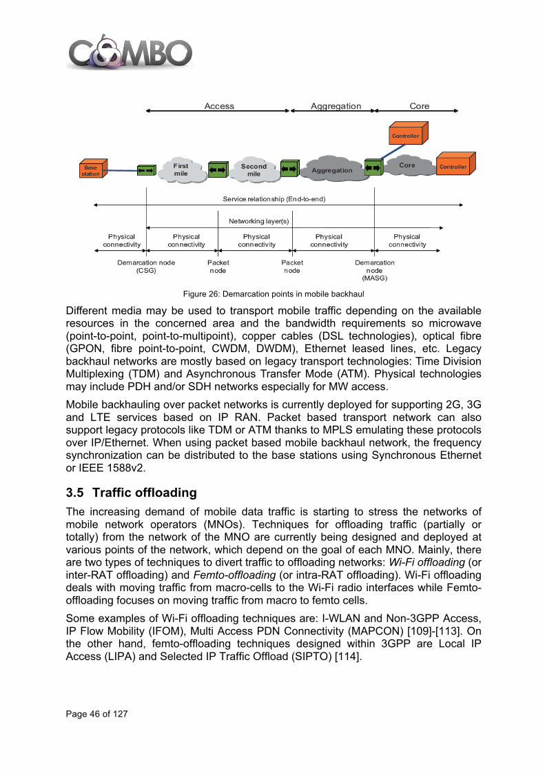
Page 46 of 127
Figure 26: Demarcation points in mobile backhaul
Different media may be used to transport mobile traffic depending on the available resources in the concerned area and the bandwidth requirements so microwave (point-to-point, point-to-multipoint), copper cables (DSL technologies), optical fibre (GPON, fibre point-to-point, CWDM, DWDM), Ethernet leased lines, etc. Legacy backhaul networks are mostly based on legacy transport technologies: Time Division Multiplexing (TDM) and Asynchronous Transfer Mode (ATM). Physical technologies may include PDH and/or SDH networks especially for MW access. Mobile backhauling over packet networks is currently deployed for supporting 2G, 3G and LTE services based on IP RAN. Packet based transport network can also support legacy protocols like TDM or ATM thanks to MPLS emulating these protocols over IP/Ethernet. When using packet based mobile backhaul network, the frequency synchronization can be distributed to the base stations using Synchronous Ethernet or IEEE 1588v2.
3.5 Traffic offloading The increasing demand of mobile data traffic is starting to stress the networks of mobile network operators (MNOs). Techniques for offloading traffic (partially or totally) from the network of the MNO are currently being designed and deployed at various points of the network, which depend on the goal of each MNO. Mainly, there are two types of techniques to divert traffic to offloading networks: Wi-Fi offloading (or inter-RAT offloading) and Femto-offloading (or intra-RAT offloading). Wi-Fi offloading deals with moving traffic from macro-cells to the Wi-Fi radio interfaces while Femto-offloading focuses on moving traffic from macro to femto cells. Some examples of Wi-Fi offloading techniques are: I-WLAN and Non-3GPP Access, IP Flow Mobility (IFOM), Multi Access PDN Connectivity (MAPCON) [109]-[113]. On the other hand, femto-offloading techniques designed within 3GPP are Local IP Access (LIPA) and Selected IP Traffic Offload (SIPTO) [114].
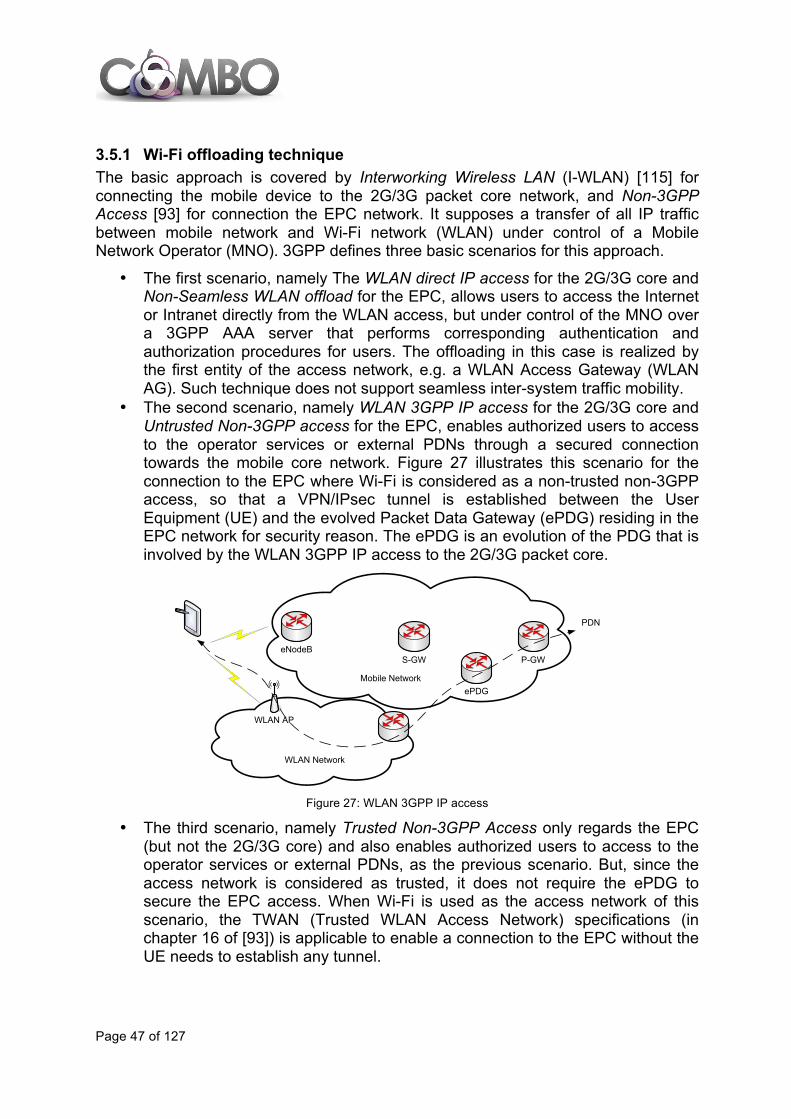
Page 47 of 127
3.5.1 Wi-Fi offloading technique The basic approach is covered by Interworking Wireless LAN (I-WLAN) [115] for connecting the mobile device to the 2G/3G packet core network, and Non-3GPP Access [93] for connection the EPC network. It supposes a transfer of all IP traffic between mobile network and Wi-Fi network (WLAN) under control of a Mobile Network Operator (MNO). 3GPP defines three basic scenarios for this approach.
• The first scenario, namely The WLAN direct IP access for the 2G/3G core and Non-Seamless WLAN offload for the EPC, allows users to access the Internet or Intranet directly from the WLAN access, but under control of the MNO over a 3GPP AAA server that performs corresponding authentication and authorization procedures for users. The offloading in this case is realized by the first entity of the access network, e.g. a WLAN Access Gateway (WLAN AG). Such technique does not support seamless inter-system traffic mobility.
• The second scenario, namely WLAN 3GPP IP access for the 2G/3G core and Untrusted Non-3GPP access for the EPC, enables authorized users to access to the operator services or external PDNs through a secured connection towards the mobile core network. Figure 27 illustrates this scenario for the connection to the EPC where Wi-Fi is considered as a non-trusted non-3GPP access, so that a VPN/IPsec tunnel is established between the User Equipment (UE) and the evolved Packet Data Gateway (ePDG) residing in the EPC network for security reason. The ePDG is an evolution of the PDG that is involved by the WLAN 3GPP IP access to the 2G/3G packet core.
Figure 27: WLAN 3GPP IP access
• The third scenario, namely Trusted Non-3GPP Access only regards the EPC (but not the 2G/3G core) and also enables authorized users to access to the operator services or external PDNs, as the previous scenario. But, since the access network is considered as trusted, it does not require the ePDG to secure the EPC access. When Wi-Fi is used as the access network of this scenario, the TWAN (Trusted WLAN Access Network) specifications (in chapter 16 of [93]) is applicable to enable a connection to the EPC without the UE needs to establish any tunnel.
WLAN AP
eNodeBP-GWS-GW
Mobile Network
WLAN Network
ePDG
PDN

Page 48 of 127
3GPP Release 8 introduced some features to maintain the IP sessions between mobile and WLAN networks ([126] for 2G/3G core and [93] for EPC). For this purpose, two mobility schemes are supported:
• Host-based mobility: it relies on Dual-stack Mobile IPv6 (DSMIPv6) and is applicable to the second and third scenarios..
• Network-based mobility: it mainly relies either on PMIP (PMIP) or GTP (GPRS Tunneling Protocol) and is only applicable to EPC for the second and third scenarios.
It allows the user to roam independently in IPv4 and IP v6 address spaces [109]. The P-GW (or a DSMIP Home Agent for the 2G/3G core) is considered as an anchor point to support seamless mobility. However, in 3GPP Rel’8 the user cannot communicate with the P-GW using both access networks simultaneously. The UE is connected through a single radio access (i.e., either 3GPP or Wi-Fi access) at a given time. Thus, flexible allocation of IP flows between access is not supported. That is, as in previous cases, all traffic related to a PDN connection should be routed through either mobile network or WLAN. However, if the UE can support simultaneously connections through different access it can bring some additional advantages. In some scenarios it is important to allow dynamic allocation of IP flows belonging to the same PDN connection between different access networks. For instance, delay-sensitive traffic (e.g. IMS call) can be served by the mobile network, while the delay-tolerant traffic (e.g. web browsing) can go through WLAN. Currently, 3GPP is being defined IP Flow Mobility (IFOM) technique [110] where the mobile terminal is able to use more than one interface to send data towards the same PDN using different paths as illustrated in Figure 28.
Figure 28: IFOM scenario
Based on the IFOM scenario the UE could add or remove IP flows over either of access within a PDN connection, effectively offloading data [117]. Thus, the granularity of access system connectivity in IFOM is IP flow-based as opposed to I-WLAN PDN connection-based granularity. While IFOM is dealing with multiple IP flows over 3GPP/non-3GPP access within a single PDN connection, the MAPCON (Multi-Access PDN connectivity) concept proposed recently by 3GPP [110]-[112] is oriented to support routing different simultaneously active PDN connections over 3GPP/non-3GPP access. The
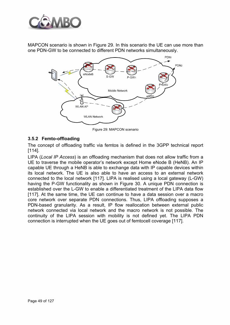
Page 49 of 127
MAPCON scenario is shown in Figure 29. In this scenario the UE can use more than one PDN-GW to be connected to different PDN networks simultaneously.
Figure 29: MAPCON scenario
3.5.2 Femto-offloading The concept of offloading traffic via femtos is defined in the 3GPP technical report [114]. LIPA (Local IP Access) is an offloading mechanism that does not allow traffic from a UE to traverse the mobile operator’s network except Home eNode B (HeNB). An IP capable UE through a HeNB is able to exchange data with IP capable devices within its local network. The UE is also able to have an access to an external network connected to the local network [117]. LIPA is realised using a local gateway (L-GW) having the P-GW functionality as shown in Figure 30. A unique PDN connection is established over the L-GW to enable a differentiated treatment of the LIPA data flow [117]. At the same time, the UE can continue to have a data session over a macro core network over separate PDN connections. Thus, LIPA offloading supposes a PDN-based granularity. As a result, IP flow reallocation between external public network connected via local network and the macro network is not possible. The continuity of the LIPA session with mobility is not defined yet. The LIPA PDN connection is interrupted when the UE goes out of femtocell coverage [117].
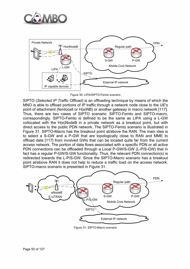
Page 50 of 127
Figure 30: LIPA/SIPTO-Femto scenario
SIPTO (Selected IP Traffic Offload) is an offloading technique by means of which the MNO is able to offload portions of IP traffic through a network node close to the UE's point of attachment (femtocell or H(e)NB) or another gateway in macro network [117]. Thus, there are two cases of SIPTO scenario: SIPTO-Femto and SIPTO-macro, correspondingly. SIPTO-Femto is defined to be the same as LIPA using a L-GW collocated with the H(e)NodeB in a private network as a breakout point, but with direct access to the public PDN network. The SIPTO-Femto scenario is illustrated in Figure 31. SIPTO-Macro has the breakout point at/above the RAN. The main idea is to select a S-GW and a P-GW that are topologically close to RAN and MME to offload data [117] from involved GWs that can be located quite far from the current access network. The portion of data flows associated with a specific PDN or all active PDN connections can be offloaded through a Local P-GW/S-GW (L-P/S-GW) that in fact has a regular P-GW/S-GW functionality. Thus, the relevant PDN connection(s) is redirected towards the L-P/S-GW. Since the SIPTO-Macro scenario has a breakout point at/above RAN it does not help to reduce a traffic load on the access network. SIPTO-macro scenario is presented in Figure 31.
Figure 31: SIPTO-Macro scenario
External IP network
L-GW
P-GWS-GW
Mobile Core Network
IP capable devices
Private NetworkH(e)NodeB
PDNRegular path
LIPASIPTO
External IP network
P-GWS-GW
Mobile Core Network
eNodeB
PDNRegular path
SIPTO
L-P/S-GWE-UTRAN

Page 51 of 127
4 FIXED EVOLUTION TRENDS
4.1 Introduction: Drivers for evolution of fixed access networks The current traffic growth promoted by high-definition TV, video-on-demand, real time IPTV, wireless traffic backhauling, online gaming, etc. requires a corresponding increase in the capacity and in the transmission speed of fixed networks [33]. Fixed architectures comprise different technologies such as copper-based networks, optical networks, fixed wireless networks and microwave solutions. Copper-based solutions are ductile enough to support an increase in the bitrate in the access that copes with some current bandwidth requirements. Fibre-based technologies are considered as the ultimate broadband solution for next-generation access and for aggregation networks, nonetheless wireless technologies are also evolving towards a network with large ubiquitous coverage. In general, access and aggregation networks are continuously challenged to evolve in order to offer higher bandwidth, while serving more users and covering longer distances with lower costs and higher resource efficiency. The access and aggregation technologies should fulfil multiple important operational requirements such as:
• Resource efficiency: as in any engineering, the maximization of the resource utilization is a key target that can be accomplished, for example, by sharing fibres or channel capacity. Resource efficiency can lead to cost reduction because a lower number of resources could be required to serve the same number of users.
• Cost efficiency: a minimal amount of CapEx and OpEx should be employed for a given target performance.
• Energy efficiency: minimizing the energy requirements can be accomplished in a static manner, by reducing the number of components which consume more energy, and dynamically, by operating with energy saving techniques, e.g., sleep-mode or stand-by schemes. Also sharing the resources among high numbers of users results in improved energy efficiency.
• Scalability: the network is expected to accommodate a greater number of users and services without degrading the network performance. Such condition is opposed to the situation where the network has a hard limit on the number of users, which, if exceeded, makes performance unacceptable for all users.
• Reliability: the network must be able to provide protection at least to the portions of the network which are shared among the highest number of users, e.g. Central Offices. Reliability is important in fixed networks since they tend to serve a large number of users through a common infrastructure.
• Delay: limited delays between users and servers are needed in next-generation network since the services that will be provided on such infrastructure (e.g., Voice-over-IP, wireless traffic backhaul, etc.) can have very strict delay requirements.
• Longer reach: longer transmission spans will be necessary in order to cover the distances between final users and the new network nodes, which will be closer to the core network when node consolidation is performed. Node consolidation is accomplished in order to lower the total number of active network nodes. In

Page 52 of 127
this process, the architecture gets benefits in terms of the power consumption, resilience, operational complexity, and control and management [34].
Some important technologies and architectures to deal with these drivers and requirements are explained in detail.
4.2 Copper access evolution During the last years the bandwidth over copper pairs has increased to support the new services offered by service providers. Current copper technology target is to provide 1 Gb/s (aggregated downlink and uplink) speed at short distances. xDSL systems are affected by interferences, where the most important interferences are those ones bound to the signals of the neighbour xDSL pairs, referred to as crosstalk. Apart from interferences caused by crosstalk, attenuation represents one of the principal limitations of transmission over copper. To reduce the attenuation impact one can either replace the cables by others with better attenuation characteristics or reduce the loop length. The former is not practical, and the latter can be reached through the approximation of the DSLAMs to the premises using cabinets or demarcation points as G.fast and Fibre to the Distribution Point (FTTdp) propose in the following sections.
4.2.1 G.fast G.fast is currently being developed by ITU-T SG15 and is expected to be approved by 2014. The G.fast concept appeared in February 2011 when, as a response to the white paper produced by the Broadband Forum explaining the need for this concept and the initial requirements (OD-263 Draft 00.14), a liaison between ITU-T SG15 and Broadband Forum emerged and ITU-T started working on a new item: “Fast Access to Subscriber Terminals” (G.fast). The idea behind G.fast is to provide ultra-high-speed copper access over the last drop (20 - 250 m) reusing the twisted pair copper lines, bringing the fibre closer to the end user premises. G.fast intends to use an extended bandwidth of 106 MHz for its first version and Discrete Multi-tone (DMT) modulation with a maximum of 2048 subcarriers (200 MHz in a second version). Its main difference with previous xDSL technologies is related to the duplexing mode.
The target aggregated rate of G.fast is 500 Mb/s while operating in the band above 17.664 MHz with an adequate guard band, in the presence of RF interference and crosstalk of 6 dB below a single disturber model, over a 200 m loop of 0.5 mm cable. As far as latency and QoS is concerned, G.fast should have a latency of less than 1 ms per direction for a packet size of 64 bytes, when there are no retransmissions. In order for G.fast to constitute a cost-effective alternative of substituting fibre in the last drop, G.fast network nodes installed in the outside plant should be very simple with reduced functionality so they can be installed in a harsh environment (manholes, poles, splices, etc.), needing zero touch operation and maintenance. One of the main motivations of using G.fast instead of FTTH is that installing fibre in buildings is expensive or even impossible for operators, and G.fast could re-use the copper lines

Page 53 of 127
already installed and ready to use inside the customer premises. Additionally, G.fast equipment could be powered from the customer, so operators will not have to use their own power supply, following a Fibre to the Distribution Point (FTTdp) approach (see section 4.7.2). Early simulation results of G.fast performance show its real potential. Results have been analysed for different pre-coding schemes, since it has not been established yet. To enable the results being as real as possible, the FEC operation and real bit-loading have been included in the simulations [36], [37].
4.2.2 Phantoming Phantoming is based on multi-pair transmission, where, if several pairs are available, it is possible to increase data rate by sending data over the different channels of the system. Phantoming provides an increase of bitrate thanks to multi-pair and multi-mode transmission. Phantoming uses differential and phantom modes formed between more than two twisted pairs for transmitting different coordinated signals at both ends of the cable at the same time. Applying phantoming on N twisted-pairs leads to transmission over 2N-1 modes, which means an improvement on the rate of up to 50% in the case of 2 twisted-pairs (3 independent modes) and up to 75% in the case of 4 twisted-pairs (7 independent modes). Hence, the main limitation of copper transmission once this technology is applied would be the physical attenuation of the cable itself. Since the crosstalk between phantom modes and between alternative modes is higher than the traditional crosstalk between differential modes, improved crosstalk cancellation algorithms are needed. Currently phantoming is considered as a future technology that could be developed after G.fast. However, ITU-T is not officially working nowadays on phantoming nor are there specific estimated dates for its commercial availability.
4.3 Cable access evolution This section describes three potentially complementary evolutionary steps on the horizon for cable infrastructure to improve the performance and capabilities of the HFC architecture, in line with an eventual transition to an IP-centric high-capacity network.
4.3.1 Upgrade from DOCSIS 3.0 to DOCSIS 3.1 DOCSIS 3.1 is an evolution of DOCSIS 3.0 that uses OFDM modulation scheme, which is also used by technologies such as DSL, LTE, WiMAX, and Wi-Fi. DOCSIS 3.1 will also be able to implement higher-order data encoding rates, namely 4096-QAM in place of the existing 256-QAM, using advanced OFDM-based electronics and by incorporating better error correction techniques, which will in turn make data transmission more spectrally efficient. The cable industry claims that DOCSIS 3.1 will provide 10 Gb/s downstream capacity and 1 Gb/s upstream. This will not be possible for most actual cable systems—a

Page 54 of 127
typical system with 860 MHz capacity might have the first 200 MHz to 250 MHz assigned to upstream, leaving 600 MHz to 650 MHz for downstream. Even with 10 bps/Hz efficiency, the actual capacity for a shared node area would be closer to 6 Gb/s than 10 Gb/s, and the capacity, will be shared among a few hundred users. With appropriate planning and node segmentation, it should be possible for cable operators using DOCSIS 3.1 to consistently, simultaneously deliver more than 100 Mb/s downstream and 25 Mb/s upstream to customers and to fully migrate the television system to IP technology, if desired. On the other hand, expansion of downstream spectrum to 1.2 GHz and maybe up to 1.7 GHz for greater capacity are also being considered[38], but this is still under evaluation and would require significant changes in network hardware. It is also important to note that higher-order QAM, such as 4096-QAM, will likely require improvement in the quality of the cables in the system and replacement of drop cables to subscriber residences [39]. DOCSIS 3.1 is designed to be backward-compatible to DOCSIS 3.0, but a customer will need a DOCSIS 3.1 modem to have DOCSIS 3.1 speeds [40]. The deployment of DOCSIS 3.1 is planned to begin in late 2014 or early 2015 [41].
4.3.2 Ethernet PON over Coax (EPoC) Architecture One possibility being considered by the cable industry for next-generation cable architecture, beyond simply upgrading DOCSIS on cable systems, is to reconfigure the cable system to operate with new electronics architecture resembling the PON architecture used by many FTTP operators. Again, the upgrade would enable the cable operator to obtain more capacity and make the system more compatible with IP data and video applications, and would be a way to make progress without wholesale replacement of the coaxial cable with fibre. The cable-TV PON architecture standard proposed by the IEEE is called Ethernet PON over Coax (EPoC). EPoC could potentially provide 10 Gbps speeds over the existing HFC architecture and further delay the need for cable operators to extend fibre. EPoC standards are currently in development and are scheduled to be complete by 2015 [42].The advantage of EPoC, relative to the current cable system, is that, once operational, it would allow a cable operator to virtually provide a dedicated IP Ethernet connection to each customer in a more efficient and direct way than using DOCSIS cable modems, and would allow cable operators and FTTP operators to be in the same marketplace for headend, hub and user premises equipment and take advantage of the economies of scale. However, it is important to note that there is no magic or free lunch in the EPoC architecture—if the coaxial portion of the cable system is not upgraded to fiber, the customers on the network are still constrained by the physical capacity of that part of the system, even if a more efficient architecture sits on top. If the cable operator does not expand fiber, the likely speeds are, as in the case of DOCSIS 3.1.
4.3.3 Mobile backhaul using cable technologies The fiber part of the HFC network can serve as a feeder for a mobile network, which can be integrated with the cable network, or from a third party operator. Even, thanks
Page 55 of 127
to the bandwidth improvement brought by DOCSIS 3.1 (or EPOC), pico-cell feeding and community or private Wi-Fi network backhaul can be provided by the cable portion of the HFC network, The advantage of the HFC architecture is that the infrastructure can be progressively upgraded to support the required bit rate increase. The second advantage is that it can support multicast/broadcast service by nature. It can be therefore smoothly integrated with eMBMS to send multicast streams from one source to multiple receivers.
4.3.4 Internet Protocol (IP) Migration and Convergence Transition to an all-IP platform is a scalable and cost-effective strategy in the long run, allowing the operator to reduce ongoing costs, increase economies of scale with other networks, communications and media industries, and operate a more uniform and scalable network. The cable industry sees the Converged Cable Access Platform (CCAP) as the next step on the road to an all-IP-based content delivery model for most cable operators. CCAP represents CableLabs consolidation of two separate data and video convergence projects—the Converged Multiservice Access Platform (CMAP) initiative led by Comcast and the Converged Edge Service Access Router (CESAR) project by Time Warner Cable3. CCAP is designed to merge the hardware for DOCSIS IP data and digital video channels into one platform. Cable networks now assign distinct blocks of available bandwidth to different types of services allowing a more dynamic provisioning of bandwidth, adapting to users’ demand for a particular type of service.
4.4 Optical access evolution
4.4.1 Next Generation PON version 2 (NG-PON2)
4.4.1.1 Introduction A new standard for Next Generation PON is currently under development by FSAN and ITU-T. FSAN is composed of telecommunications service providers, equipment suppliers and independent test labs that aim at providing contributions to ITU-T SG15 Q2 in order to promote the development of global standards on PON technologies (FSAN it is not a Standard Development Organization by itself). ITU-T with the support of FSAN is currently developing the new Next Generation PON version 2 (NG-PON2) standards under ITU-T Recommendation series G.989, which is the evolution of XG-PON ITU-T series G.987. NG-PON2 will be the long-term solution in the PON evolution. In summer of 2012, it was decided that TWDM-PON would be the primary solution for NG-PON2. Basically TWDM is a solution in which multiple TDM/TDMA based PON
3“CableLabs Updates Technical Report on Converged Cable Access Platform,” June 14, 2011, http://www.cablelabs.com/news/pr/2011/11_pr_ccap_061411.html
Page 56 of 127
systems are wavelength multiplexed to provide a higher data rate level. A typical scheme could be four 10Gb/s signals multiplexed with a typical split ratio of 1:64 or 1:128, so that it could provide a maximum aggregated throughput of 40 Gb/s in the downstream and in the upstream. Bidirectional transmission is accomplished by use of WDM on a single fibre. The downstream wavelengths could be placed around 1600 nm and the upstream wavelengths near 1535 nm, so it can coexist with traditional RF Video Overlay (that uses the optical range 1550-1560 nm). However, as the standardization process is not currently finished, these specific details may slightly change (however the current draft is stable and it is expected to finalize the Recommendation in 2014 with the idea that the industry could provide the first products based on this standard by 2015-2016). PtP WDM wavelengths are also planned to be specified in the standard as an optional solution which complements TWDM-PON, where WDM channels are used to allow a virtual point to point architecture additionally to a TWDM-PON system in the same fibre. PtP WDM should ensure negligible linear and non-linear interferences (e.g., Raman crosstalk) with the RF video signal to coexist with it. So, the standard will specify the characteristics of TWDM-PON and the PtP WDM overlay. Recommendation ITU-T G.989.2 is being drawn up and some requirements that describe NG-PON2 are defined in recommendation ITU-T G.989.1:
• An aggregate bandwidth of 40 Gb/s in the downstream direction, and 10 up to 40 Gb/s in the upstream direction.
• Support of legacy ODN, where ODN based on power splitters must be re-used. • Co-existence with GPON, 10G-GPON and RF-video is desirable. RF overlay will
continue to be used into the foreseeable future to support video delivery. • A minimum reach of 40 km with passive elements. NG-PON2 systems must also
be capable of reaching 60 km, preferably using passive elements in the outside plant.
• A minimum split ratio of 1:64, however higher splitting ratios will be needed (supporting 64 to 1000 ONUs).
• An NG-PON2 ONU should be able to support a minimum throughput of 1 Gb/s. • No technology roadblocks or bottlenecks.
Other features such as efficiency, management traffic, power management, etc. are also being considered in the scope of NG-PON2.
4.4.1.2 NG-PON2 migration issues NG-PON2 is being defined as capable of co-existence with legacy systems on the legacy PON infrastructure. Co-existence with GPON/XG-PON has been enabled using a new co-existence element (CEx), which is a passive combiner is a filter allowing co-existence of NG-PON2 signals with GPON and XG-PON signals on the same ODN) with wavelength

Page 57 of 127
filtering in the OLTs. The operator must be enabled to upgrade single customers on demand offering a smooth migration path from GPON or XG-PON to NG-PON24. Figure 32 describes two migration use cases: (A) where the full ODN is re-used without any reconfiguration of the ODN, only the co-existence device combining legacy and NG-PON2 OLT has to be inserted, and (B) in which a remote WDM is installed to specialized PON drops with reduced fibre outlet (which requires power splitter reconfiguration) or if optical budget enables to extend the splitting ratio. The constraints for migration will obviously and strongly depend on already deployed ODNs characteristics and especially the splitters’ locations on the ODN:
• With a single remote splitter installed in a street cabinet, on the one hand, WDM passive devices (see Figure 32.B) could be quite easily added in the street cabinet close to the splitter, but on the other hand, if spare fibres are available in the feeder, new dedicated splitters could be used so that co-existence would no longer be so stringent.
• With single splitter at the CO, all fibre churning can be easily done even if both OLTs are not co-located, which would be the case when CO consolidation occurs.
• With multi-stage splitters (i.e., a multiple splitting level ODN), the constraints for individual migration are obviously the most significant ones as they would require additional fibre deployment down to the lowest splitting stage and definitively should legitimate “full co-existence” scenarios. It is no longer possible to insert WDM devices without duplicating the fibre drop infrastructure.
A)
4 All GPON, XG-PON and NG-PON2 technologies will be able to co-exist and the current G.989.2 draft wavelength plan has been designed to allow it.
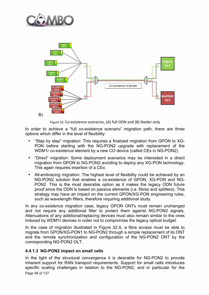
Page 58 of 127
B)
Figure 32: Co-‐existence scenarios, (A) full ODN and (B) feeder only
In order to achieve a “full co-existence scenario” migration path, there are three options which differ in the level of flexibility:
• “Step by step” migration: This requires a finalized migration from GPON to XG-PON before starting with the NG-PON2 upgrade with replacement of the WDM1r co-existence element by a new CO device (called CEx in NG-PON2).
• “Direct” migration: Some deployment scenarios may be interested in a direct migration from GPON to NG-PON2 avoiding to deploy any XG-PON technology. This again requires insertion of a CEx.
• All-embracing migration: The highest level of flexibility could be achieved by an NG-PON2 solution that enables a co-existence of GPON, XG-PON and NG-PON2. This is the most desirable option as it makes the legacy ODN future proof since the ODN is based on passive elements (i.e. fibres and splitters). This strategy may have an impact on the current GPON/XG-PON engineering rules, such as wavelength filters, therefore requiring additional study.
In any co-existence migration case, legacy GPON ONTs must remain unchanged and not require any additional filter to protect them against NG-PON2 signals. Attenuations of any additional/replacing devices must also remain similar to the ones induced by WDM1r devices in order not to compromise the legacy optical budget. In the case of migration illustrated in Figure 32.A, a fibre access must be able to migrate from GPON/XG-PON1 to NG-PON2 through a simple replacement of its ONT and the remote synchronization and configuration of the NG-PON2 ONT by the corresponding NG-PON2 OLT.
4.4.1.3 NG-PON2 impact on small cells In the light of the structural convergence it is desirable for NG-PON2 to provide inherent support for RAN transport requirements. Support for small cells introduces specific scaling challenges in relation to the NG-PON2, and in particular for the
Page 59 of 127
scenario where NG-PON2 is assumed to bridge the final link of the transport chain to the Radio Base Station (RBS)/ RRU (Remote Radio Unit) access site. In this scenario, the large number of expected small cells will drive the number of clients that must be served by NG-PON2. Hence, NG-PON2 must be able to support RAN transport requirements to a large number of clients. Beyond this, RAN architecture aspects related to the coordination and the logical interconnection between different RAN sites must be understood. For example in the case where NG-PON2 is used as a common transport solution for small cells and macro cells, the need for coordination of small cells with macro cells may lead to effects where the transport requirements to the macro sites are dramatically increased beyond that of the bare macro cell as coordination is handled over the backhaul infrastructure. Considering the bare transport requirements to individual RAN access sites, two cases can be identified: backhaul and fronthaul (for more information on fronthaul, see section 5.3.2). For (packet-based) backhaul, peak bandwidth requirements per RBS around 1 Gb/s can be expected, with latency requirements driven by synchronization requirements. For (CPRI-based) fronthaul, peak bandwidth requirements can extend to up to 10 Gb/s combined with more stringent latency requirements in accordance with CPRI transport requirements. With the large number of clients that must be supported, in order to minimize operational complexity, NG-PON2 should also provide support for automation and avoid the need for manual intervention during operation or configuration. Considering the different technology cycles for fixed and mobile it is also important that the transport infrastructure is flexible and scalable to support higher capacity per client and an increasing number of clients. From a solution perspective it is clear that based on the RAN transport requirements, fronthaul must be carried over dedicated PtP links or wavelengths. For packet backhaul, relaxed requirements allow additionally for TDM to be exploited. However, due to RAN synchronization requirements, the upstream TDMA is limited to static or quasi static TDMA in contrast to dynamic TDMA with dynamic bandwidth allocation. Based on these finding we may discuss small cell support provided by the proposed NG-PON2 solutions. TWDM is the primary solution for NG-PON2 as proposed by FSAN. The protocol layer is likely to be based on an extension of XG-PON including both an asymmetric and symmetric solution with respect to downstream/upstream bandwidth. In terms of fronthaul support (requiring dedicated wavelengths), TWDM supports provisioning of 10G (downstream) wavelengths. As 10G wavelengths within TWDM are commonly shared between multiple clients using TDM to provide access in the range of 300-600 Mb/s, provisioning entire wavelengths with 10 Gb/s service to single clients significantly reduces the total TWDM-PON client count. In addition, there is yet no mapping for CPRI over XG-PON. The applicability of TWDM to fronthaul is therefore limited. In terms of backhaul, TWDM provides a more scalable solution where bandwidth to individual clients can be scaled through TDM up to 10 Gb/s. TDM provides scalable client throughput, but due to backhaul requirements, there are no statistical multiplexing gains (dynamic bandwidth allocation) enabled by TDM. The optional support for PtP wavelengths in NG-PON2, through the 48-channels WDM-PON flavour, provides an alternative means for small cell transport. The option
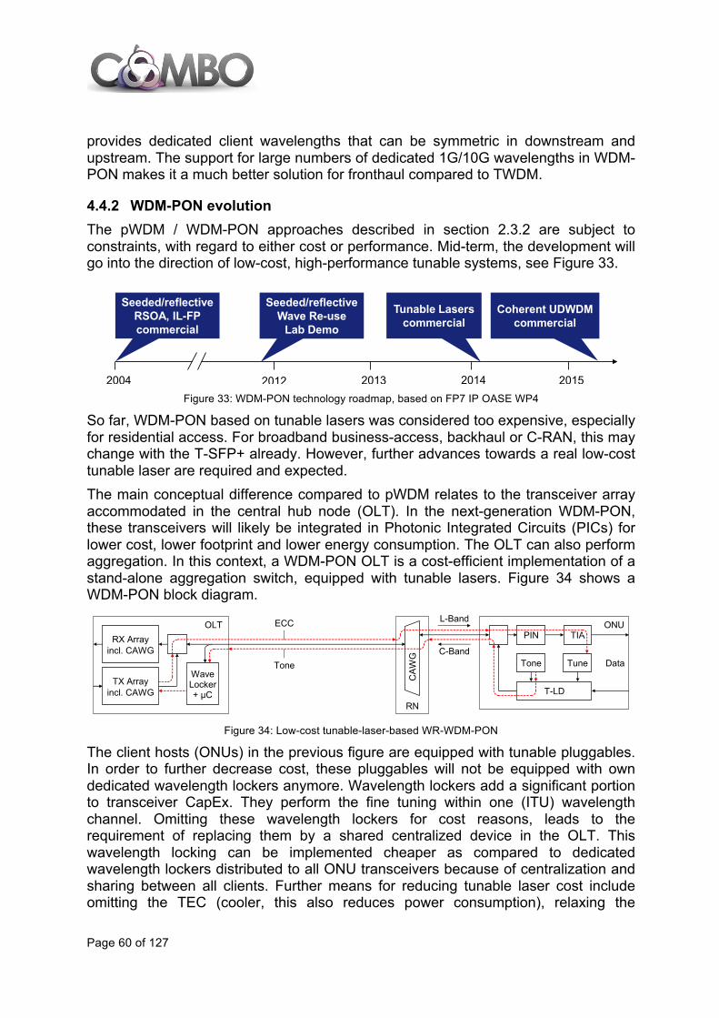
Page 60 of 127
provides dedicated client wavelengths that can be symmetric in downstream and upstream. The support for large numbers of dedicated 1G/10G wavelengths in WDM-PON makes it a much better solution for fronthaul compared to TWDM.
4.4.2 WDM-PON evolution The pWDM / WDM-PON approaches described in section 2.3.2 are subject to constraints, with regard to either cost or performance. Mid-term, the development will go into the direction of low-cost, high-performance tunable systems, see Figure 33.
Figure 33: WDM-PON technology roadmap, based on FP7 IP OASE WP4
So far, WDM-PON based on tunable lasers was considered too expensive, especially for residential access. For broadband business-access, backhaul or C-RAN, this may change with the T-SFP+ already. However, further advances towards a real low-cost tunable laser are required and expected. The main conceptual difference compared to pWDM relates to the transceiver array accommodated in the central hub node (OLT). In the next-generation WDM-PON, these transceivers will likely be integrated in Photonic Integrated Circuits (PICs) for lower cost, lower footprint and lower energy consumption. The OLT can also perform aggregation. In this context, a WDM-PON OLT is a cost-efficient implementation of a stand-alone aggregation switch, equipped with tunable lasers. Figure 34 shows a WDM-PON block diagram.
Figure 34: Low-cost tunable-laser-based WR-WDM-PON
The client hosts (ONUs) in the previous figure are equipped with tunable pluggables. In order to further decrease cost, these pluggables will not be equipped with own dedicated wavelength lockers anymore. Wavelength lockers add a significant portion to transceiver CapEx. They perform the fine tuning within one (ITU) wavelength channel. Omitting these wavelength lockers for cost reasons, leads to the requirement of replacing them by a shared centralized device in the OLT. This wavelength locking can be implemented cheaper as compared to dedicated wavelength lockers distributed to all ONU transceivers because of centralization and sharing between all clients. Further means for reducing tunable laser cost include omitting the TEC (cooler, this also reduces power consumption), relaxing the
2004 2012 2013 2014 2015
Seeded/reflectiveWave Re-use
Lab Demo
Seeded/reflectiveRSOA, IL-FPcommercial
Tunable Laserscommercial
Coherent UDWDMcommercial
ONU OLTRX Array
incl. CAWG
TX Arrayincl. CAWG
WaveLocker+ µC
ECC
Tone
T-LD
L-Band
C-Band
CAW
G
PIN TIA
RN
Tone Tune Data
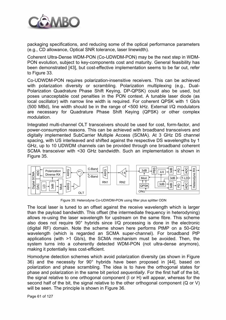
Page 61 of 127
packaging specifications, and reducing some of the optical performance parameters (e.g., CD allowance, Optical SNR tolerance, laser linewidth). Coherent Ultra-Dense WDM-PON (Co-UDWDM-PON) may be the next step in WDM-PON evolution, subject to key-components cost and maturity. General feasibility has been demonstrated [43], but cost-effective implementation seems to be far out, refer to Figure 33. Co-UDWDM-PON requires polarization-insensitive receivers. This can be achieved with polarization diversity or scrambling. Polarization multiplexing (e.g., Dual-Polarization Quadrature Phase Shift Keying, DP-QPSK) could also be used, but poses unacceptable cost penalties in the PON context. A tunable laser diode (as local oscillator) with narrow line width is required. For coherent QPSK with 1 Gb/s (500 MBd), line width should be in the range of <500 kHz. External I/Q modulators are necessary for Quadrature Phase Shift Keying (QPSK) or other complex modulation. Integrated multi-channel OLT transceivers should be used for cost, form-factor, and power-consumption reasons. This can be achieved with broadband transceivers and digitally implemented SubCarrier Multiple Access (SCMA). At 3 GHz DS channel spacing, with US interleaved and shifted against the respective DS wavelengths by 1 GHz, up to 10 UDWDM channels can be provided through one broadband coherent SCMA transceiver with <30 GHz bandwidth. Such an implementation is shown in Figure 35.
Figure 35: Heterodyne Co-UDWDM-PON using filter plus splitter ODN
The local laser is tuned to an offset against the receive wavelength which is larger than the payload bandwidth. This offset (the intermediate frequency in heterodyning) allows re-using the laser wavelength for upstream on the same fibre. This scheme also does not require 90° hybrids since I/Q processing is done in the electronic (digital RF) domain. Note the scheme shown here performs PtMP on a 50-GHz wavelength (which is regarded an SCMA super-channel). For broadband PtP applications (with >1 Gb/s), the SCMA mechanism must be avoided. Then, the system turns into a coherently detected WDM-PON (not ultra-dense anymore), making it potentially less cost-efficient. Homodyne detection schemes which avoid polarization diversity (as shown in Figure 36) and the necessity for 90° hybrids have been proposed in [44], based on polarization and phase scrambling. The idea is to have the orthogonal states for phase and polarization in the same bit period sequentially. For the first half of the bit, the signal relative to one orthogonal component (I or H) will appear, whereas for the second half of the bit, the signal relative to the other orthogonal component (Q or V) will be seen. The principle is shown in Figure 36.
OLT
RN1
AWG
RN2
1:k
AWG
AWG
ONU
Mod.
3dB3dB
T-LD
ADC
PBS
Het
erod
yne
RX
3dB
λ/4 PD
3dB
ADC
PDQPSK
ADC
DAC
PolarizationDiverse RX
Dig
ital S
CM
A
LD 3dB
Mod
. 3dB
C-Band
C-Band

Page 62 of 127
Figure 36: Homodyne detection without polarization diversity and without 90° hybrids
Within each symbol of duration Tb, the phase of the local laser is scrambled by means of an RZ50 (Return-to-Zero with 50% duty cycle) signal which is synchronized with the receiver clock recovery (CLK Rec.). The RZ50 signal generates, within each symbol interval, two time slots of duration Tb/2 with fixed 0° to 90° phase modulation. One slot represents the I component, the second slot represents the phase-shifted Q component. This is demonstrated in the insert in Figure 37. This scheme operates like a phase-diversity system. The local laser does not need to be phase-coherent with the incoming optical carrier. This can be regarded as an intradyne receiver with near-zero intermediate frequency. As such, dual-fibre working is required. Next-generation WDM-PONs allow further functions which lead to CapEx or OpEx savings. They support Single-Fibre Working (SFW) for efficient access / backhaul fibre usage. This requirement was adapted from residential access. For upstream / downstream separation, they make use of cyclic Arrayed Waveguide Gratings (AWGs) as WDM filters. Cyclic AWGs allow simultaneous per-port access to multiple WDM bands, e.g., C-band and L-band. These bands are then assigned to upstream and downstream, leading to a simple low-loss solution to WDM-PON SFW. Cyclic AWGs allow additional functions in the OAM field. Two such functions are shown in Figure 37.
Figure 37: OAM aspects of WDM-PON. A: OTDR monitoring. B: protection enabled by 2:N AWGs
Figure 37.A shows additional fibre-plant monitoring, down to the individual clients, by means of an OTDR (Optical Time-Domain Reflectometer). Here, the OTDR is operated in the U-band, i.e., the wavelength region between 1625 nm and 1675 nm. This is a typical OTDR operations region, and non-traffic-affecting overlay is again provided via the cyclic AWG. Unlike standard OTDRs, the devices used for WDM-PON must be tunable (in the U-band) in order to be able to individually monitor each client-connecting fibre. Compared to standard PONs (which use power splitters rather than WDM filters), this adds the advantage that individual clients can be monitored unambiguously.
QH
QV
IH
IV
t0 t0+Tb t0+2Tbt
QH
QV
IH
IV
LDData
US
DS
Pol. Scr.
3dB
CLK Rec.
3dB
Tb Tb/2
-+
Data
RZ50
Tb/2
Freq. Doubler
PM
ONU
C-Band
C-Band
RN
AWG
OLT
U-BandOTDR
…
TRXArrayincl.
AWG
L/U ONUTRXPassive LT
(U-BandReflector)
2:N
AW
G
…
TRXArray 1
TRXArray 2
OLT
RN
ONUTRX
A) B)

Page 63 of 127
Figure 37.B shows additional fibre protection for the fibre which carries the multiplexed WDM signal. Protection of this part of the fibre plant is most effective since failure of these fibres simultaneously affect all connected clients. The protection shown in Figure 37.B is based on 2:N cyclic AWGs. Here, a second feeder-fibre port has been added. This adds little complexity to AWGs since their general internal design is based on an N:N structure anyway. In the OLT, this protection can be combined with single or duplicated (as shown) transceiver arrays. Obviously, single-array design has lower CapEx, but lower transceiver availability as well.
4.4.3 OFDM-PON Orthogonal Frequency Division Multiplexing (OFDM) technology was originally conceived to achieve better transmission properties for bit streams by using several low bit rate subcarriers transporting multiple signals simultaneously. In P2MP, such as PON, multiple-access techniques need to be applied in order to share the same transmission medium by several users. In Orthogonal Frequency Division Multiple Access (OFDMA) systems, the downlink multiplexing and the multiple-access mechanisms in the uplink are based on orthogonal subcarrier allocation (currently OFDM-PON systems are not commercially available and many OFDM-PON prototypes use TDMA in the upstream instead OFDMA, because OFDMA systems suffer optical beat interference as their main limitation). As shown in Figure 38, an OFDMA-PON system could consist of an OLT located in the CO and several ONTs (located at the customer premises). The OLT would manage the downlink traffic into different subcarriers which would travel along the optical distribution network being demultiplexed at the user side and each user would be assigned a different set of subcarriers both for downlink and uplink transmission.
Figure 38: OFDMA-PON general architecture
With regard to the upstream channel, each ONT could be assigned a group of subcarriers within a shared OFDM band, although different frequency bands could be used as well combined with an OFDMA+TDMA system. In the previous years, the OFDMA-PON concept has been introduced in the optics world as an interesting alternative that could provide high-capacity, long-reach and
RN L1,L2
OFDMAOLT
Customer’s Premises
Central Office
λ
λ
OFDMAONT
OFDMAONT
OFDMAONT

Page 64 of 127
cost-effective operation for PONs [45], [46] in the future. In this context, an OFDMA-PON solution has been developed within the EU FP7 framework between the years 2010 and 2013 in the ACCORDANCE project [47] and also been techno-economically assessed together with other approaches like WDM-PON, UDWDM-PON and TDMA/WDM-PON concepts in the EU FP7 IP OASE project. Currently there are two main alternatives to implement OFDMA-PON:
• I/Q modulation in the optical field, i.e., optical OFDM. • Electrical OFDM modulation on an RF signal that is modulated in optical
intensity. As far as the physical layer is concerned, the main benefit of OFDM is that each of the sub-carriers transmitted in parallel has much lower bitrate than the aggregated signal, which could make the system less susceptible to chromatic and polarization mode dispersion effects. Therefore, aggregated data of several Gb/s could travel much longer without the need for dispersion compensating modules. OFDMA systems with aggregated rates of 100 Gb/s over PON networks with a reach similar than GPON have been proposed in [45]. Additionally a hybrid long-reach PON architecture combining the spectral efficiency of OFDMA with WDM and coherent detection has also been reported with a capacity of 1 Tb/s [48]. Concerning limitations, the high number of orthogonal subcarriers causes a high Peak-to-Average Power Ratio (PAPR) and consequently non-linearities in the fibre appear. Besides, due to the long duration of the OFDM symbol, frequency deviations or phase noise may affect the signal reception and cause Inter Carrier Interference (ICI). Another drawback of OFDMA-PON systems is the beating interference produced by several ONTs transmitting with similar wavelengths whose signals get combined. Nowadays, the main disadvantage of the described solution lays on the high implementation cost due to fast electronic and relative complexity of the optical components, which makes a commercial deployment difficult in the short to medium term.
4.5 Fixed wireless evolution: Wi-Fi evolution
4.5.1 Wi-Fi radio standard evolution Regarding radio technology evolution, the IEEE802.11ad standard will provide a new multi-Gb/s connectivity at 60 GHz. The objective is to extend Wi-Fi capabilities with short range Gb/s connectivity. The 60 GHz band is also called the “spectrum Eldorado” because 9 GHz are available; conversely the coverage is reduced to room connectivity. The challenge is to transform it in a commercial reality avoiding confusion of systems and standards and developing low cost and low power consumption products. First products with IEEE802.11ad are expected to be available later in 2014 or 2015. Moreover, a study group named High Efficiency WLAN (HEW) has been created in 2013 at 802.11 to define a follow to 802.11ac.

Page 65 of 127
4.5.2 Wi-Fi architecture enhancements Evolutions of fixed wireless architecture are, as for now, driven by current standardization activities which tend to promote more generalized use of Wi-Fi access mainly within 3GPP, BBF, GSMA and Wi-Fi Alliance standardization bodies. The first step was to control the Wi-Fi access using a SIM-based authentication method and was achieved by relying on the Hotspot2.0 release 1 that can be yet considered at the state of the art (see 2.4.3). A further step is to enable the mobile device to connect the mobile core network using a Wi-Fi access. This topic firstly concerns 3GPP, which specifies different way for that purpose (detailed in 3.5.1), and the BBF, which adapts those specifications for the context of the fixed access network in TR-203 (Interworking between Next Generation Fixed and 3GPP Wireless Access [121]) and TR-291 (Nodal Requirements for Interworking between Next Generation Fixed and 3GPP Wireless Access [122]). A more advanced step, which is also an effective functional convergence, aims at providing a common subscriber policy management function for both fixed and mobile networks. It has been yet specified by 3GPP ([123]) and is currently under specification at BBF in WT-300 (Nodal Requirements for Converged Policy Management [124]).
4.5.3 Wi-Fi hotspot utilization enhancement The Wi-Fi Alliance is currently working on a new release of the Hotspot 2.0 specifications which provide the following additional features (related to Online Set-Up and Policy Provisioning): • Immediate account provisioning: a streamlined process establishes a new user
account at the point of access, driving a common provisioning methodology across vendors.
• Operator Policy: operator-specific policies, including network selection policy, are provided to the subscriber.
4.5.4 Network-assisted Wi-Fi access selection for mobile devices 3GPP TS 23.402 [93] defines the Access Network Discovery and Selection Function (ANDSF) that enables the UE to be assisted by the network for detection and selection of non-3GPP access networks, particularly for 802.11 WLAN networks. The main goal of that function is the provisioning of the UE by the network with:
• Access network discovery information (e.g., Wi-Fi SSID available in proximity). • Access network selection criteria (e.g., weighted list of available wireless access
networks: 3GPP preferred to Wi-Fi, Wi-Fi SSID1 preferred to Wi-Fi SSID2). • Routing policies (e.g., VoIP over 3G, Internet over Wi-Fi).
Thus, ANDSF enables the operator to control the load balancing between 3GPP and non-3GPP access via appropriate policies that can be provided to the UE in both push and pull modes.
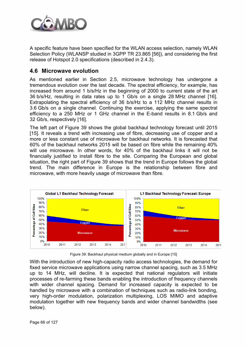
Page 66 of 127
A specific feature have been specified for the WLAN access selection, namely WLAN Selection Policy (WLANSP studied in 3GPP TR 23.865 [56]), and considering the first release of Hotspot 2.0 specifications (described in 2.4.3).
4.6 Microwave evolution As mentioned earlier in Section 2.5, microwave technology has undergone a tremendous evolution over the last decade. The spectral efficiency, for example, has increased from around 1 b/s/Hz in the beginning of 2000 to current state of the art 36 b/s/Hz, resulting in data rates up to 1 Gb/s on a single 28 MHz channel [16]. Extrapolating the spectral efficiency of 36 b/s/Hz to a 112 MHz channel results in 3.6 Gb/s on a single channel. Continuing the exercise, applying the same spectral efficiency to a 250 MHz or 1 GHz channel in the E-band results in 8.1 Gb/s and 32 Gb/s, respectively [16]. The left part of Figure 39 shows the global backhaul technology forecast until 2015 [15]. It reveals a trend with increasing use of fibre, decreasing use of copper and a more or less constant use of microwave for backhaul networks. It is forecasted that 60% of the backhaul networks 2015 will be based on fibre while the remaining 40% will use microwave. In other words, for 40% of the backhaul links it will not be financially justified to install fibre to the site. Comparing the European and global situation, the right part of Figure 39 shows that the trend in Europe follows the global trend. The main difference in Europe is the relationship between fibre and microwave, with more heavily usage of microwave than fibre.
Figure 39: Backhaul physical medium globally and in Europe [15]
With the introduction of new high-capacity radio access technologies, the demand for fixed service microwave applications using narrow channel spacing, such as 3.5 MHz up to 14 MHz, will decline. It is expected that national regulators will initiate processes of re-farming these bands enabling the introduction of frequency channels with wider channel spacing. Demand for increased capacity is expected to be handled by microwave with a combination of techniques such as radio-link bonding, very high-order modulation, polarization multiplexing, LOS MIMO and adaptive modulation together with new frequency bands and wider channel bandwidths (see below).

Page 67 of 127
4.6.1 New frequency bands Microwave is expected to move into higher frequency bands. Therefore, its evolution in the new frequency bands up to 2020 is summarized below [55]:
• The 70/80 GHz band has after a decade with limited equipment and deployments started to take-off in 2013-2014. High performance, price competitive equipment is now becoming available from many vendors. The main usage is for a few kilometres hop lengths with up to multi-Gb/s capacities, i.e. backhaul to support LTE evolution (macro-sites and pre-aggregation sites) or general fibre extension/closure backhaul in metro areas. The 70/80 GHz band is expected to rapidly grow and within 5 years account for approximately 10% of the overall point-to-point microwave backhaul market in terms of number of new radio deployments/year.
• The 60 GHz band is currently expected to be about 2 years behind the 70/80 GHz when it comes to deployment take-off and equipment maturity. The main expected usage of the 60 GHz band is for small cell backhaul and (since often unlicensed) for non-operator use. Depending on the take-off of the small cell backhaul market, it is expected that the 60 GHz market will take off during 2015-2016 but will then rapidly grow to similar volumes as the 70/80 GHz band within 5 years, i.e., approximately 10% of total microwave backhaul market in terms of number of new radio deployments/year.
• The 42 GHz band is in simple terms seen as a new "add-on" to the very popular 38 GHz band, which is becoming quite crowded in many metro areas. The total volume of these two bands today amounts to approximately 10% and it is expected that the volume remains at this level in the coming years, but with a shift from today’s dominating 38 GHz to more and more of 42 GHz.
• The exploitation of the upper part of the E-band, i.e., the 95 GHz band, is expected to take off beyond 2016 after the 70/80 GHz band is occupied utilizing the commercialization of mm-wave technologies, e.g., in terms of packaging and building practises.
• The spectrum above 100 GHz offers several large, low-loss transmission windows. For example, in the 145 GHz band, there is 6 GHz of bandwidth available (141–147 GHz). Such high frequency bands require the use of narrow antenna beams to compensate for the small effective antenna aperture. On the flip side, the small wavelength enables the design of very compact antennas and radios making them appropriate for high-density backhaul applications. Getting access to these frequencies for commercial use – for both mobile and fixed services – will also bring challenges, for example in test and verification and building such radios cost-effectively, as well as the lead-time for national regulators to open up the new bands.
To sum up, the above-mentioned bands are in general considered by the industry to be essential to support the RAN evolution with point-to-point microwave backhaul.
4.6.2 LOS MIMO MIMO technologies are commonly supported in modern radio access technologies, for example, in IEEE 802.11ac and LTE. It is also already a commodity since a few years for modern microwave networks using polarization multiplexing. Common
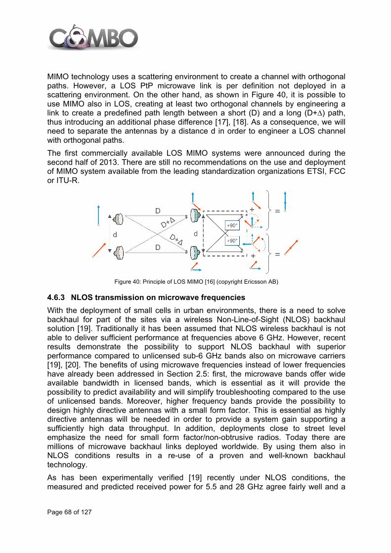
Page 68 of 127
MIMO technology uses a scattering environment to create a channel with orthogonal paths. However, a LOS PtP microwave link is per definition not deployed in a scattering environment. On the other hand, as shown in Figure 40, it is possible to use MIMO also in LOS, creating at least two orthogonal channels by engineering a link to create a predefined path length between a short (D) and a long (D+∆) path, thus introducing an additional phase difference [17], [18]. As a consequence, we will need to separate the antennas by a distance d in order to engineer a LOS channel with orthogonal paths. The first commercially available LOS MIMO systems were announced during the second half of 2013. There are still no recommendations on the use and deployment of MIMO system available from the leading standardization organizations ETSI, FCC or ITU-R.
Figure 40: Principle of LOS MIMO [16] (copyright Ericsson AB)
4.6.3 NLOS transmission on microwave frequencies With the deployment of small cells in urban environments, there is a need to solve backhaul for part of the sites via a wireless Non-Line-of-Sight (NLOS) backhaul solution [19]. Traditionally it has been assumed that NLOS wireless backhaul is not able to deliver sufficient performance at frequencies above 6 GHz. However, recent results demonstrate the possibility to support NLOS backhaul with superior performance compared to unlicensed sub-6 GHz bands also on microwave carriers [19], [20]. The benefits of using microwave frequencies instead of lower frequencies have already been addressed in Section 2.5: first, the microwave bands offer wide available bandwidth in licensed bands, which is essential as it will provide the possibility to predict availability and will simplify troubleshooting compared to the use of unlicensed bands. Moreover, higher frequency bands provide the possibility to design highly directive antennas with a small form factor. This is essential as highly directive antennas will be needed in order to provide a system gain supporting a sufficiently high data throughput. In addition, deployments close to street level emphasize the need for small form factor/non-obtrusive radios. Today there are millions of microwave backhaul links deployed worldwide. By using them also in NLOS conditions results in a re-use of a proven and well-known backhaul technology. As has been experimentally verified [19] recently under NLOS conditions, the measured and predicted received power for 5.5 and 28 GHz agree fairly well and a

Page 69 of 127
stable throughput of 400 Mb/s is achieved at 28 GHz up to 6 m deviation from LOS propagation.
4.7 Access architectures evolution proposals This section analyses the fixed access network evolution focusing more on the architecture rather than the technology. Some technologies described in the previous sections are used in these access architectures evolution proposals (for example, g.fast in the fibre to the distribution point, see 4.7.2).
4.7.1 Long reach PON and Central office consolidation Long reach PON (LR-PON) is a solution based on PON architecture that extends system reach to enable a greater potential reduction of costs. This solution increases the coverage span of PONs beyond the traditional 20 km, extending the physical reach of the access network to the core network. A general LR-PON architecture consolidates multiple headend devices known as OLTs, which were previously located at COs, by moving them to a new main CO (see Figure 41), and deploying an extended feeder fibre between the COs and the main CO. Typically, a new remote node (RN) is added to the network in the old location of the OLT, i.e., the CO, or the Local Exchange (LE) in LR-PON architectures. With the provision of the new extended geographic coverage, LR-PON combines optical access and metro into an integrated system.
Figure 41: General architecture of a Long Reach PON: Branch and Tree architecture
In general, the LR-PON concept can simplify the network, reducing the number of equipment interfaces, network elements and nodes, where access headends are closer to the backbone network. In Figures 41 and 42, Dfeeder is the fibre span in the feeder section of the Branch-and-Tree solution, while Dring is the length of the fibre segment in the ring in the Ring-and-Spur solution. DCO-Cab and DCab-ONU denote the fibre distance between the CO or LE and the Cabinet, and between the Cabinet and the ONU, respectively. LR-PONs allow the use of more expensive devices at the LE since their cost is shared among a
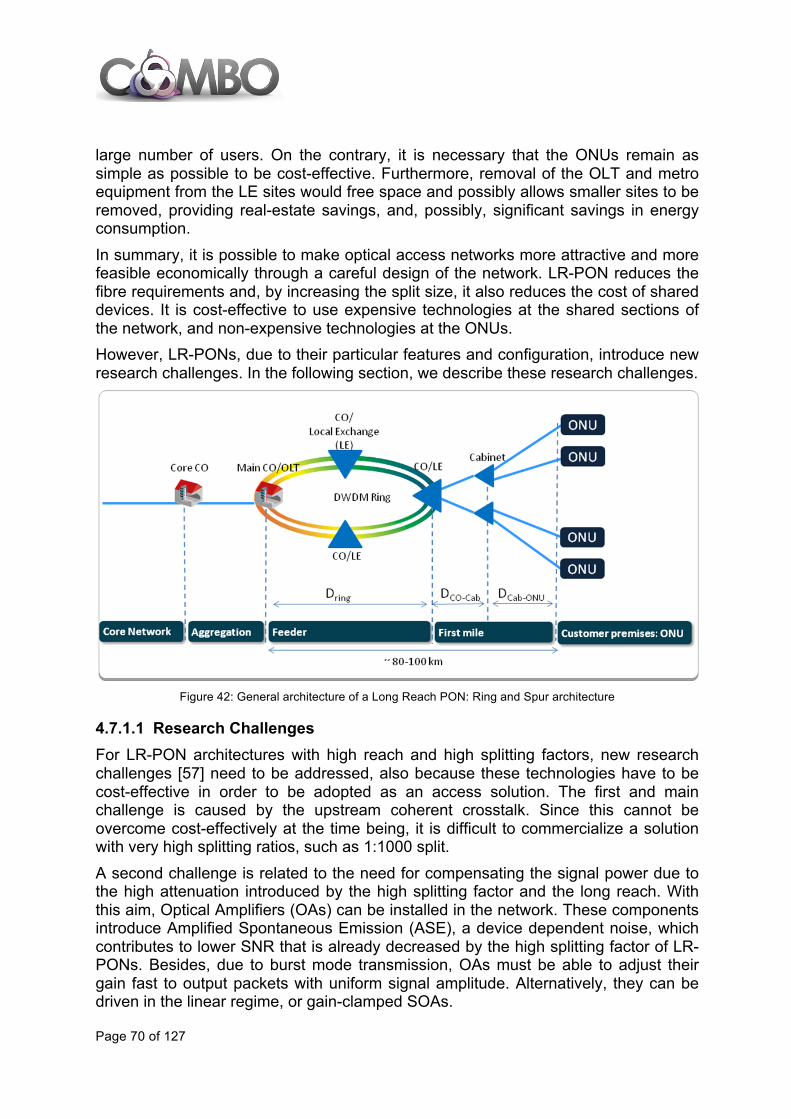
Page 70 of 127
large number of users. On the contrary, it is necessary that the ONUs remain as simple as possible to be cost-effective. Furthermore, removal of the OLT and metro equipment from the LE sites would free space and possibly allows smaller sites to be removed, providing real-estate savings, and, possibly, significant savings in energy consumption. In summary, it is possible to make optical access networks more attractive and more feasible economically through a careful design of the network. LR-PON reduces the fibre requirements and, by increasing the split size, it also reduces the cost of shared devices. It is cost-effective to use expensive technologies at the shared sections of the network, and non-expensive technologies at the ONUs. However, LR-PONs, due to their particular features and configuration, introduce new research challenges. In the following section, we describe these research challenges.
Figure 42: General architecture of a Long Reach PON: Ring and Spur architecture
4.7.1.1 Research Challenges For LR-PON architectures with high reach and high splitting factors, new research challenges [57] need to be addressed, also because these technologies have to be cost-effective in order to be adopted as an access solution. The first and main challenge is caused by the upstream coherent crosstalk. Since this cannot be overcome cost-effectively at the time being, it is difficult to commercialize a solution with very high splitting ratios, such as 1:1000 split. A second challenge is related to the need for compensating the signal power due to the high attenuation introduced by the high splitting factor and the long reach. With this aim, Optical Amplifiers (OAs) can be installed in the network. These components introduce Amplified Spontaneous Emission (ASE), a device dependent noise, which contributes to lower SNR that is already decreased by the high splitting factor of LR-PONs. Besides, due to burst mode transmission, OAs must be able to adjust their gain fast to output packets with uniform signal amplitude. Alternatively, they can be driven in the linear regime, or gain-clamped SOAs.

Page 71 of 127
In order to lower ONU equipment costs, it is necessary to install cost-effective optical sources. A first solution to reach this aim is to use uncooled transmitter which are temperature-dependent and, for this reason, can produce wavelength drift of +/- 6.5 nm. Wavelength drifts can cause problems when a DWDM system is used because a precise wavelength transmission is required. Some implementations of a burst-mode receiver are available for current access technologies, but, as in LR-PON the speed of links and the number of customers supported is scaled up, it is necessary to investigate new burst-mode receivers with a high sensitivity and a wide dynamic range [58]. Table 4 includes a summary of the most important architectures for Long-Reach PON, in order to observe the proposed evolution available in literature. In particular, we report the topology of each architecture which can be either Branch-and-Tree or Ring-and-Spur. The number of channels refers to the number of wavelengths used to transmit in a single direction: upstream (US) or downstream (DS). We also specify the line rate used in US and DS channels, and the maximum number of users that can be served. In this table, the total distance is split into the three sections of the network, which are defined in Figures 41 and 42. Finally, the “Split ratio” indicates the total power split ratio achieved through both single splitter or cascaded splitters.
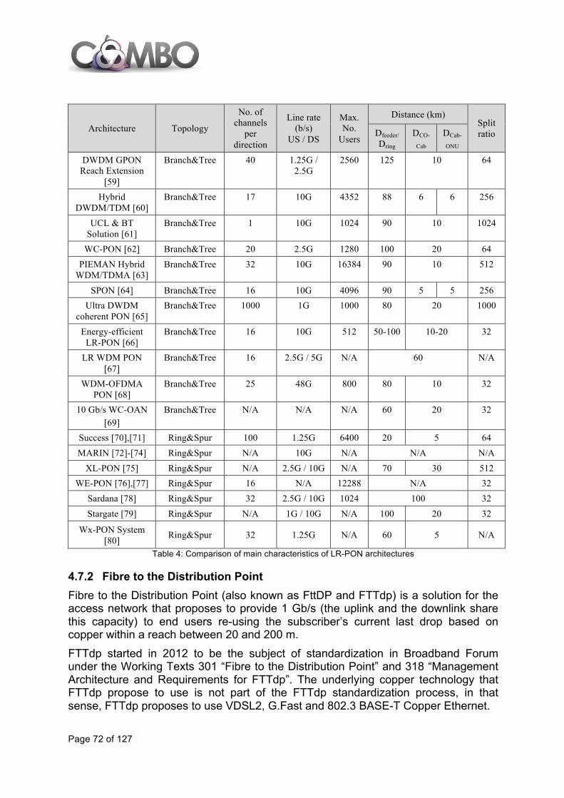
Page 72 of 127
Architecture Topology
No. of channels
per direction
Line rate (b/s)
US / DS
Max. No.
Users
Distance (km) Split ratio Dfeeder/
Dring DCO-
Cab DCab-
ONU
DWDM GPON Reach Extension
[59]
Branch&Tree 40 1.25G / 2.5G
2560 125 10 64
Hybrid DWDM/TDM [60]
Branch&Tree 17 10G 4352 88 6 6 256
UCL & BT Solution [61]
Branch&Tree 1 10G 1024 90 10 1024
WC-PON [62] Branch&Tree 20 2.5G 1280 100 20 64 PIEMAN Hybrid
WDM/TDMA [63] Branch&Tree 32 10G 16384 90 10 512
SPON [64] Branch&Tree 16 10G 4096 90 5 5 256 Ultra DWDM
coherent PON [65] Branch&Tree 1000 1G 1000 80 20 1000
Energy-efficient LR-PON [66]
Branch&Tree 16 10G 512 50-100 10-20 32
LR WDM PON [67]
Branch&Tree 16 2.5G / 5G N/A 60 N/A
WDM-OFDMA PON [68]
Branch&Tree 25 48G 800 80 10 32
10 Gb/s WC-OAN [69]
Branch&Tree N/A N/A N/A 60 20 32
Success [70],[71] Ring&Spur 100 1.25G 6400 20 5 64 MARIN [72]-[74] Ring&Spur N/A 10G N/A N/A N/A
XL-PON [75] Ring&Spur N/A 2.5G / 10G N/A 70 30 512 WE-PON [76],[77] Ring&Spur 16 N/A 12288 N/A 32
Sardana [78] Ring&Spur 32 2.5G / 10G 1024 100 32 Stargate [79] Ring&Spur N/A 1G / 10G N/A 100 20 32
Wx-PON System [80] Ring&Spur 32 1.25G N/A 60 5 N/A
Table 4: Comparison of main characteristics of LR-PON architectures
4.7.2 Fibre to the Distribution Point Fibre to the Distribution Point (also known as FttDP and FTTdp) is a solution for the access network that proposes to provide 1 Gb/s (the uplink and the downlink share this capacity) to end users re-using the subscriber’s current last drop based on copper within a reach between 20 and 200 m. FTTdp started in 2012 to be the subject of standardization in Broadband Forum under the Working Texts 301 “Fibre to the Distribution Point” and 318 “Management Architecture and Requirements for FTTdp”. The underlying copper technology that FTTdp propose to use is not part of the FTTdp standardization process, in that sense, FTTdp proposes to use VDSL2, G.Fast and 802.3 BASE-T Copper Ethernet.

Page 73 of 127
The network equipment must be physically small so as to be suitable for location at a pole top, in a street pillar, in a small underground enclosure or even inside the customer’s building but not in the customer’s home. This device, the Demarcation Point Unit or DPU, could be used for both single subscriber and multi-subscriber installations, where a typical configuration of 1 to 16 subscribers per DPU is foreseen. The main backhaul technologies included in the WT 301 for FTTdp are mainly based on fibre (IEEE802.3 Gigabit Ethernet, ITU-T G-PON, IEEE EPON and their evolutions) although copper technologies are also considered (e.g., bonded copper pairs). Some requirements for FTTdp solutions are: simple equipment, low cost, low power consumption, powered by the subscriber, self-installing and easy to operate. In some environments, it could be also needed to support local loop unbundling and the simultaneous use of POTS and reverse power feed on the same drop-wire (VoIP could be the alternative way to offer the voice service, as the copper pairs will not reach the CO).
4.7.3 Wireless solutions for fixed broadband replacement This section provides an introduction to wireless alternatives that could be used by access network operators to replace fixed technologies, avoiding to re-use or to install cables in the last drop up to the customer’s premises. The main motivation for replacing fixed technologies by wireless solutions is to reduce the costs of providing FTTH connections. FTTH deployments are more cost-efficient when the number of customer per building is high, so all the deployed elements and the infrastructure built are used by many users and their cost can be shared among all of them. In broadband deployments with an estimated low number of customers per building, the connection cost per customer is higher and FTTH solutions could not be profitable. In such cases, FTTB or FTTN are typically used instead FTTH in order to increase the number of households and decrease the total cost per customer. The alternatives proposed in this section are considered to be used in low penetration areas with a low number of connected customers per building and may constitute a temporal suspension until the conditions for complete FTTH deployment are achieved.
4.7.3.1 General architecture for WLD This new Wireless Local Drop architecture or WLD is similar to a traditional FTTB or FTTN architecture, and it is composed of the following three elements:
• A Multi-Dwelling Unit (MDU). Located in the last network termination point of the access network, the MDU is responsible of the physical layer and layer 2 processing. It is composed of an ONU (Optical Network Unit) that is connected to the central office using a shared fibre following a point-to-multipoint PON approach.
• A point-to-multipoint wireless transceiver (PtMP WLD). This element establishes a (most likely directional) radio link with the wireless receivers located inside the

Page 74 of 127
customer premises. It also implements some radio resources management and security functions and the interface with the MDU.
• A domestic point-to-point wireless transceiver (PtP WLD). It corresponds to the wireless device located in the customer side that connects the home network to the point-to-multipoint wireless transceiver.
The architecture is represented in Figure 43:
Figure 43: Wireless Local Drop main elements
The MDU for this application has the same kind of functionality used in MDUs in cabinets for FTTB/FTTN solutions. The assumption for the MDU interface to the PtMP WLD element is that it will be Ethernet, so a single MDU may attend several point-to-multipoint WLD elements, as it can support several Ethernet interfaces. Additionally, the MDU could have a fibre interface based on xPON or AON for example. Some initial requirements are the following:
• Triple play support is assumed by default. • Minimum range for the wireless link: 10-15 m with a minimum aggregated peak
data rate between 40-50 Mb/s (to be shared among 3 or 4 customers). • Interference free as possible. • Easy deployment & operation: no radio planning required, NLOS between the
PtMP and the PtP WLD wireless transceivers is preferable, low power consumption, easy installation with management & monitoring capabilities.
• Standard and cost-effective.
4.7.3.2 Operating scenarios for WLD Urban and suburban deployments are some operating scenarios foreseen for the WLD operation.

Page 75 of 127
• Urban deployment (for the purposes of this analysis) is characterized by multi-floor buildings with a relatively high number of potential homes to be connected per building (but only some of them will be connected). Homes can be characterized as exterior, if the signal can arrive at the customer-side WLD element from outside the building, or interior, if the network side of the WLD is installed inside the building served. Several alternatives are possible to support the WLD in this environment: coverage from a different building, coverage from the outside of the same building and coverage from inside the same building.
• Suburban deployment is characterized by a lower density of dwellings (one or two per building). Distance between buildings is also considered to be longer on average. In this case, only coverage from outside the building is considered.
4.7.3.3 Candidate technologies for the WLD radio link Taking into account the aspects indicated in the previous section, the following two radio technologies are considered prime candidates for the implementation of a WLD solution:
• IEEE 802.11n: Wi-Fi technology at 5 GHz band seems the most natural candidate for WLD support, as the availability of the spectrum is practically universal. Other advantages are better penetration characteristics (compared to higher frequencies), better directivity characteristics than lower frequencies (compared to LTE or WiMAX), relatively high transmission power, use of 40 MHz channels and more spectrum available (in the EU, 20 channels of 20 MHz bandwidth each are available for Wi-Fi, from 5180 to 5320 MHz and from 5500 to 5700 MHz).
• TDD (Time Division Duplex) LTE: the use of the TDD mode of LTE is another alternative for the WLD radio interface. Two main operating frequencies for a TD-LTE solution could be used: TDD at 2.6 GHz and at 3.5 GHz (currently being used for WiMAX in most countries) with a minimum bandwidth of 20 MHz is required to support the capacity expected for WLD. In principle, it is assumed that the PtMP WLD part can be implemented reusing a HeNodeB (Home eNodeB, i.e., a femtocell) and the PtP WLD would be an LTE UE (user equipment). However, the users’ traffic should not go through the EPC (Evolved Packet Core). TDD-LTE is considered a fallback in case those Wi-Fi-based solutions are not feasible for any reason.
Several technological solutions have been discarded in an initial analysis, even if they are feasible from the technical viewpoint.
• WiMAX: Although in terms of its technical characteristics, WiMAX may be an adequate solution for the WLD radio interface, its unclear future, the lack of vendors and the low economies of scale advise not to consider it.
• FDD (Frequency Division Duplex) LTE: although FDD LTE may be an adequate solution from the technical viewpoint, it is considered that the use of the spectrum for providing other services (i.e., mobile broadband services) makes more sense from the economic viewpoint.

Page 76 of 127
• 60 GHz solutions: the main problem is that, in short/medium term, this is not expected to be cost effective enough to meet the requirements for the WLD solution.
4.8 Aggregation network evolution The service expansion offered by operators has resulted in a multiplicity of services (e.g., residential, mobile, business) often aggregated on separate networks (fixed and mobile) using separate equipment, even when belonging to the same company. In the context of the aggregation network evolution one of the current trends is to provide long reach multi-service infrastructures. These networks seamlessly group different services (i.e., wireless and wireline) which may be backhauled through separated access networks whose extent and composition in terms of “first mile”, feeder and aggregation may vary depending on the actual deployed scenario and operator’s policy. Indeed, the current lack of synergy among the backhauling networks may lead to inefficient resource multiplication resulting in non-optimized global costs. The integration in a unique multi-service aggregation network will be invariably driven by both the necessity of coping with the growth of bandwidth demand and the evolution of the strategies specific to each operator’s business model (e.g., reducing the CapEX). Some basic requirements of such integration are:
• The backhaul infrastructure must support traffic grooming, aggregation and transport while interoperating seamlessly with the edge domain to provide a differentiated services with advanced SLAs.
• It must scale bandwidth flexibly and cost effectively to dynamically turn up and down services.
• It must reduce both CapEx and OpEx ensuring appropriate OAM functions and, when needed, with service aware applications management.
This evolution of the multi-service aggregation network is expected to make use of scalable L2 networking technologies (e.g., MPLS-TP and Carrier Ethernet) and effective L0/L1 (optical) transport capacity (e.g., WDM and OTN). The transport granularity may, consequently, vary according to the specific deployment spanning from a wavelength (L0) to OTN ODUk (k=1, 2, 3, 4), to a more flexible packet VLAN/LSP/PW. Figure 44 depicts the transport of different wireless and wireline services over a unified optical metro / aggregation network. With respect to the current approach, the extent of the aggregation segment is expected to penetrate closer towards the first mile. This leads to overlap, in some way, with the feeder; the actual split in segments (i.e., first mile, feeder, aggregation) and sub-segments (i.e., sub-networks) will, however, keep different profiles depending on the operator and geographical region.
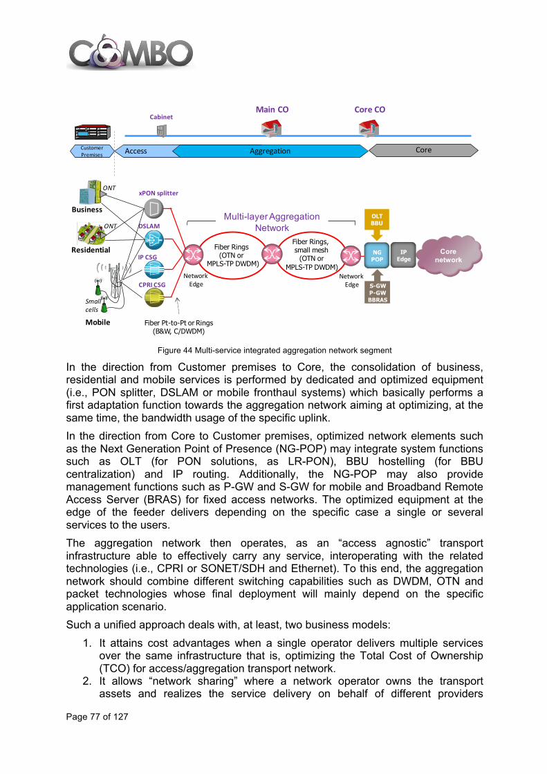
Page 77 of 127
Figure 44 Multi-service integrated aggregation network segment
In the direction from Customer premises to Core, the consolidation of business, residential and mobile services is performed by dedicated and optimized equipment (i.e., PON splitter, DSLAM or mobile fronthaul systems) which basically performs a first adaptation function towards the aggregation network aiming at optimizing, at the same time, the bandwidth usage of the specific uplink. In the direction from Core to Customer premises, optimized network elements such as the Next Generation Point of Presence (NG-POP) may integrate system functions such as OLT (for PON solutions, as LR-PON), BBU hostelling (for BBU centralization) and IP routing. Additionally, the NG-POP may also provide management functions such as P-GW and S-GW for mobile and Broadband Remote Access Server (BRAS) for fixed access networks. The optimized equipment at the edge of the feeder delivers depending on the specific case a single or several services to the users. The aggregation network then operates, as an “access agnostic” transport infrastructure able to effectively carry any service, interoperating with the related technologies (i.e., CPRI or SONET/SDH and Ethernet). To this end, the aggregation network should combine different switching capabilities such as DWDM, OTN and packet technologies whose final deployment will mainly depend on the specific application scenario. Such a unified approach deals with, at least, two business models:
1. It attains cost advantages when a single operator delivers multiple services over the same infrastructure that is, optimizing the Total Cost of Ownership (TCO) for access/aggregation transport network.
2. It allows “network sharing” where a network operator owns the transport assets and realizes the service delivery on behalf of different providers
Cabinet
Access AggregationCustomer Premises
Core COMain CO
Core
DSLAM
IP CSG
CPRI CSG
Business
xPON splitter
Residential
Mobile
ONT
ONT
Smallcells
Corenetwork
NGPOP
IP Edge
OLTBBU
S-GWP-GWBBRAS
Fiber Pt-to-Pt or Rings(B&W, C/DWDM)
Fiber Rings(OTN or
MPLS-TP DWDM)
Fiber Rings, small mesh
(OTN orMPLS-TP DWDM)
Multi-layerAggregationNetwork
Network Edge
Network Edge
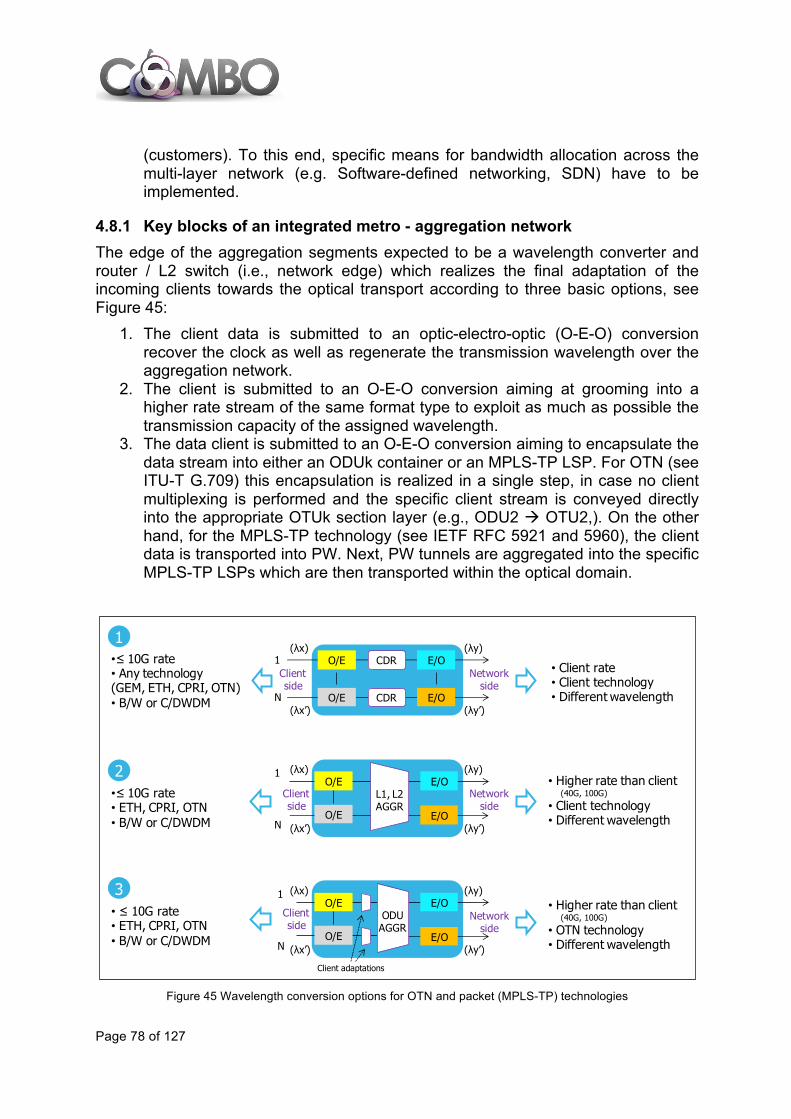
Page 78 of 127
(customers). To this end, specific means for bandwidth allocation across the multi-layer network (e.g. Software-defined networking, SDN) have to be implemented.
4.8.1 Key blocks of an integrated metro - aggregation network The edge of the aggregation segments expected to be a wavelength converter and router / L2 switch (i.e., network edge) which realizes the final adaptation of the incoming clients towards the optical transport according to three basic options, see Figure 45:
1. The client data is submitted to an optic-electro-optic (O-E-O) conversion recover the clock as well as regenerate the transmission wavelength over the aggregation network.
2. The client is submitted to an O-E-O conversion aiming at grooming into a higher rate stream of the same format type to exploit as much as possible the transmission capacity of the assigned wavelength.
3. The data client is submitted to an O-E-O conversion aiming to encapsulate the data stream into either an ODUk container or an MPLS-TP LSP. For OTN (see ITU-T G.709) this encapsulation is realized in a single step, in case no client multiplexing is performed and the specific client stream is conveyed directly into the appropriate OTUk section layer (e.g., ODU2 à OTU2,). On the other hand, for the MPLS-TP technology (see IETF RFC 5921 and 5960), the client data is transported into PW. Next, PW tunnels are aggregated into the specific MPLS-TP LSPs which are then transported within the optical domain.
Figure 45 Wavelength conversion options for OTN and packet (MPLS-TP) technologies
O/E CDR E/O
O/E CDR E/O
1
N
Clientside
Networkside
O/E
O/E
1
N
L1, L2 AGGR
E/O
• Client rate • Client technology• Different wavelength
E/O
O/E
O/E
1
N
ODUAGGR
E/O
E/O
Client adaptations
(λx)
(λx’) (λy’)
(λy)
(λx)
(λx’) (λy’)
(λy)• Higher rate than client
(40G, 100G)
• Client technology• Different wavelength
• Higher rate than client (40G, 100G)
• OTN technology• Different wavelength
•≤ 10G rate • Any technology(GEM, ETH, CPRI, OTN)• B/W or C/DWDM
•≤ 10G rate • ETH, CPRI, OTN• B/W or C/DWDM
• ≤ 10G rate • ETH, CPRI, OTN• B/W or C/DWDM
(λx)
(λx’) (λy’)
(λy)
1
2
3
Clientside
Clientside
Networkside
Networkside
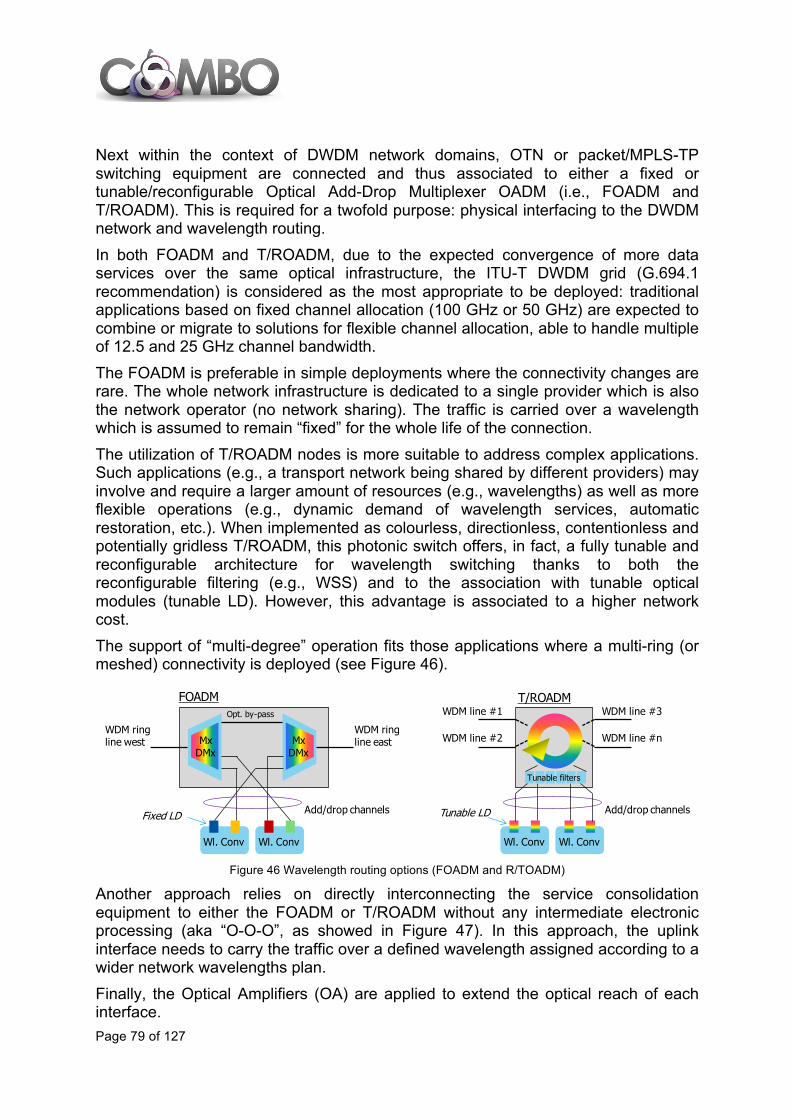
Page 79 of 127
Next within the context of DWDM network domains, OTN or packet/MPLS-TP switching equipment are connected and thus associated to either a fixed or tunable/reconfigurable Optical Add-Drop Multiplexer OADM (i.e., FOADM and T/ROADM). This is required for a twofold purpose: physical interfacing to the DWDM network and wavelength routing. In both FOADM and T/ROADM, due to the expected convergence of more data services over the same optical infrastructure, the ITU-T DWDM grid (G.694.1 recommendation) is considered as the most appropriate to be deployed: traditional applications based on fixed channel allocation (100 GHz or 50 GHz) are expected to combine or migrate to solutions for flexible channel allocation, able to handle multiple of 12.5 and 25 GHz channel bandwidth. The FOADM is preferable in simple deployments where the connectivity changes are rare. The whole network infrastructure is dedicated to a single provider which is also the network operator (no network sharing). The traffic is carried over a wavelength which is assumed to remain “fixed” for the whole life of the connection. The utilization of T/ROADM nodes is more suitable to address complex applications. Such applications (e.g., a transport network being shared by different providers) may involve and require a larger amount of resources (e.g., wavelengths) as well as more flexible operations (e.g., dynamic demand of wavelength services, automatic restoration, etc.). When implemented as colourless, directionless, contentionless and potentially gridless T/ROADM, this photonic switch offers, in fact, a fully tunable and reconfigurable architecture for wavelength switching thanks to both the reconfigurable filtering (e.g., WSS) and to the association with tunable optical modules (tunable LD). However, this advantage is associated to a higher network cost. The support of “multi-degree” operation fits those applications where a multi-ring (or meshed) connectivity is deployed (see Figure 46).
Figure 46 Wavelength routing options (FOADM and R/TOADM)
Another approach relies on directly interconnecting the service consolidation equipment to either the FOADM or T/ROADM without any intermediate electronic processing (aka “O-O-O”, as showed in Figure 47). In this approach, the uplink interface needs to carry the traffic over a defined wavelength assigned according to a wider network wavelengths plan. Finally, the Optical Amplifiers (OA) are applied to extend the optical reach of each interface.
Wl. ConvWl. Conv
FOADM
Add/drop channels
Opt. by-pass
WDM ring line east
WDM ringline west
Wl. ConvWl. Conv
Add/drop channelsFixed LD Tunable LD
MxDMx
MxDMx
Tunable filters
WDM line #1
WDM line #2
WDM line #3
WDM line #n
T/ROADM
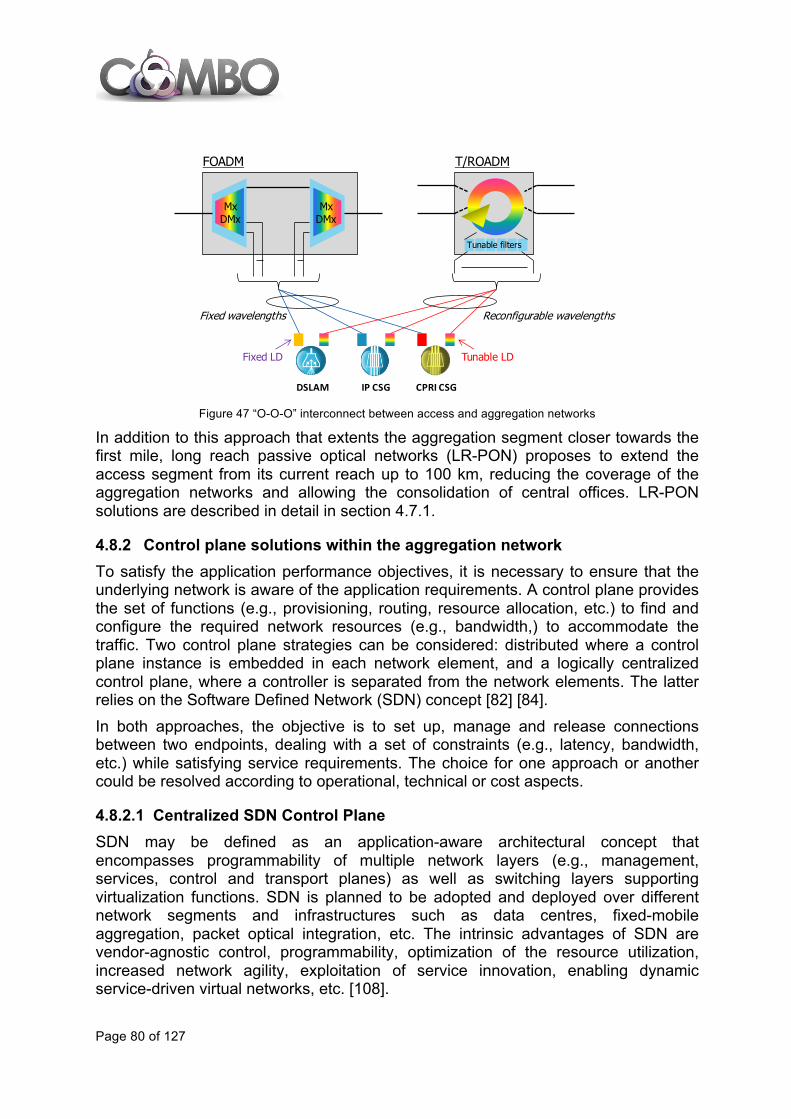
Page 80 of 127
Figure 47 “O-O-O” interconnect between access and aggregation networks
In addition to this approach that extents the aggregation segment closer towards the first mile, long reach passive optical networks (LR-PON) proposes to extend the access segment from its current reach up to 100 km, reducing the coverage of the aggregation networks and allowing the consolidation of central offices. LR-PON solutions are described in detail in section 4.7.1.
4.8.2 Control plane solutions within the aggregation network To satisfy the application performance objectives, it is necessary to ensure that the underlying network is aware of the application requirements. A control plane provides the set of functions (e.g., provisioning, routing, resource allocation, etc.) to find and configure the required network resources (e.g., bandwidth,) to accommodate the traffic. Two control plane strategies can be considered: distributed where a control plane instance is embedded in each network element, and a logically centralized control plane, where a controller is separated from the network elements. The latter relies on the Software Defined Network (SDN) concept [82] [84]. In both approaches, the objective is to set up, manage and release connections between two endpoints, dealing with a set of constraints (e.g., latency, bandwidth, etc.) while satisfying service requirements. The choice for one approach or another could be resolved according to operational, technical or cost aspects.
4.8.2.1 Centralized SDN Control Plane SDN may be defined as an application-aware architectural concept that encompasses programmability of multiple network layers (e.g., management, services, control and transport planes) as well as switching layers supporting virtualization functions. SDN is planned to be adopted and deployed over different network segments and infrastructures such as data centres, fixed-mobile aggregation, packet optical integration, etc. The intrinsic advantages of SDN are vendor-agnostic control, programmability, optimization of the resource utilization, increased network agility, exploitation of service innovation, enabling dynamic service-driven virtual networks, etc. [108].
DSLAM IP CSG CPRI CSG
FOADM
MxDMx
MxDMx
Tunable filters
T/ROADM
Fixed wavelengths Reconfigurable wavelengths
Tunable LDFixed LD

Page 81 of 127
SDN provides a framework for applications to request and manipulate services provided by the network. To this end, SDN requires complete decoupling of the network control plane from the forwarding / switching plane. Such a separation facilitates the direct programmability by applications (e.g., routing, access-control, mobility, etc.). As depicted in Figure 48, a key component is the logically centralized controller that communicates with the switching hardware using a standardized SouthBound interface (SBI). This SBI interface (e.g. OpenFlow) is responsible for conducting the abstraction of the hardware-specific details as well as the configuration of the switching / forwarding fabrics for the establishment of the data flows. The interworking of applications and services with the network infrastructure is handled by the controller via an Application Programming Interface (API). Indeed a NorthBound interface (NBI) is defined to deliver network awareness to service and application layers via open APIs. By doing so, the application layer is able to directly program the controller. This means that no only new services can be dynamically (on-demand) instantiated but also existing services can be modified aiming at attaining, for instance, a better use of the network resources, optimization of the performance objectives or dealing with the new or modified application/service requirements [74].
Figure 48 Centralized SDN control plane architecture
4.8.2.2 Distributed GMPLS Control Plane GMPLS [85] is a mature distributed control plane solution being standardized by the IETF during the last decade, and mostly deployed within backbone networks. However, to address the emerging requirements arising in multi-service aggregation networks (e.g., dynamic provisioning, efficient traffic grooming, etc.) the benefits provided by the GMPLS control plane can be also leveraged in the aggregation infrastructure. Shortly, GMPLS provides the required control functions for the

Page 82 of 127
automatic provisioning and recovery of end-to-end connections (LSPs). GMPLS has been defined to control multiple switching layers and technologies such as packet, TDM, lambda, fibre, etc. The basis of GMPLS is a protocol suite that consists of three main pillars: a signalling (Resource Reservation - Traffic Engineering - RSVP-TE) protocol used for the distributed provisioning of connections, a routing protocol (IS-IS-TE or OSPF-TE) for the network topology and resource dissemination, and a Link Management, discovery and verification Protocol (LMP). The GMPLS controller is co-located with the respective switching hardware / fabric. This means that each network element is controlled by a GMPLS controller. To ensure the communication (i.e., control message exchange) among the GMPLS controllers a Data Communication Network (DCN) is required.
Figure 49 – Distributed GMPLS control plane and API between the applications and EMS/NMS
In current networks, the centralized Network Management System (NMS) interacts with the GMPLS controller to trigger the provisioning of connections. Analogous to the SDN principles, the NMS can be upgraded with a defined API enabling the operations of applications and services (Figure 49) for the re-configurability and optimization of the network resources. However, the control functionalities (e.g., routing, traffic engineering, etc.) in specific scenarios (e.g., multi-domain and multi-layer networks) are constrained. For instance, in multi-layer networks (i.e., infrastructures operating two or more switching technologies, e.g., packet and optical), the interworking between control plane entities governing each layer is reduced due to the use of proprietary control protocols. This restricts the visibility of the resources involved in each layer, which does complicate the cooperation and network resource optimization. An alternative currently receiving much interest relies

Page 83 of 127
on extracting key functions such as the path computation from the distributed control plane. This is mainly capitalized by the so-termed PCE [86]. The PCE can be defined as an application that is capable of computing a network path based on the network graph and resource availability and applying a set of constraints during the path computation. Thus, the PCE results an effective solution for the route computation within scenarios with limited control cooperation (e.g., topology dissemination) such as multi-domain or multi-layer networks.
4.9 Roadmap for fixed network evolution Fixed broadband over copper is the most common broadband access technology in use in the world [87]. However, it is envisioned that the dominant means for accessing the Internet and other broadband services will be based on fibre in the long run since access speeds offered by fibre set the stage for the new definition of broadband. Lifestyle changes and bandwidth demanding applications like video-conferencing, workflow application through corporate Virtual Private Network, and other collaborative peer-to-peer type of applications and services will become common. Therefore, broadband access characteristics need to be enhanced by symmetric downstream/upstream access speed and QoS. The use of hybrid fibre-copper solutions with a considerably lower CapEx for the broadband roll out is envisioned as an intermediate step towards a full fibre-based architecture. With vectoring, currently being in the field trial stage it is expected to achieve 100 Mb/s in VDSL2 lines over a few hundred meters. Moreover, the G.fast standard is expected to be finished by 2014Q1 and first prototypes will appear around 2014Q4 (see section 4.2.1). In G.fast, the termination point is moved a couple of hundred meters outside the customer premises and there is no need of going into the individual customers’ homes. First deployments are expected in 2015 – 2016 and will offer aggregate bit rates reaching 1 Gb/s. In 2011, prototypes of a new technology based on phantom modes appeared in the market but this solution is still in a very early stage of development and very important drawbacks (robustness, complexity, size, etc.) have put a question mark over its commercial deployment in the long run. Access networks based on fibre are evolving towards new technical alternatives including NG-PON2 according to ITU-T Recommendation G.989, which is expected to be approved in 2014. TWDM-PON has been selected as the primary solution for NG-PON2, and it is expected to reach commercial stage between 2015 and 2016. Simultaneously, new solutions for the NG-PON evolution (i.e., NG-PON3) are expected to appear in the long term, i.e. by the year 2020. As far as microwave access is concerned, it is expected that it will evolve from 38 GHz to 42 GHz in the coming years [55]. Moreover, in 2015 – 2016 microwave access at 60 GHz will take off, covering around 10% of the total microwave backhaul market in terms of number of new radio deployments/year by 2020 – 2021. Regarding microwave evolution at 70/80 GHz it is expected that 10% of the overall point-to-point microwave backhaul market in terms of number of new radio

Page 84 of 127
deployments/year within five years. The exploitation of the upper part of the E-band, i.e., the 95 GHz band, is expected to take off beyond 2016. Wi-Fi is one of the most ubiquitous wireless communication technologies in use today, and is normally reserved for the IEEE 802.11 standards using unlicensed spectrum bands. Currently, the Wi-Fi and WiGig alliances are working on the 802.11ac and 802.11ad standards respectively. In 2013, the Wi-Fi Alliance started its certification program for the 802.11ac standard, which is already appearing in some products in pre-certified form and it is expected to reach 1 Gb/s for multi-station, and 500 Mb/s on single link using the 5 GHz band. The second wave of this standard is expected to be agreed on in 2014Q1. Regarding 802.11ad, the standard was accepted by the WiGig alliance in 2012 and the first chipsets are available now with the target of a commercial deployment by the end of 2014 or beginning of 2015. This new standard uses the 60 GHz band to achieve a theoretical maximum throughput of up to 7 Gb/s. Furthermore, Wi-Fi is considered as a complementary technology for mobile communications and solutions to offload mobile traffic are being developed. The packet optical network integrating both L2 (i.e., MPLS-TP) and L1 (i.e., WDM, OTN) technologies is one of the adopted solutions targeting scalable and bandwidth-flexible aggregation segments. Such a solution is commercially available since WDM is a mature transport technology highly deployed during the last decade, and MPLS-TP nodes have been commercialized since 2011. Besides, enhancements to DWDM technology have been introduced (ITU-T G.694.1 - 2012) in such a way to support flexible grid allocation (with Nx 12.5, 25, 50, 100 GHz channels spacing), optimizing the resource allocation with respect to the actual bandwidth needed. Similarly, also OTN, so far mainly deployed in core backbone networks, has evolved from the basic standard functions (around 2000), including means for flexible bandwidth connection (ODUflex). Consequently, the deployment of the combined/integrated solution (i.e., MPLS-TP/WSON) for new fronthaul/backhaul or replacing legacy SONET/SDH networks is expected to be initiated in a time window between 2013 and 2016. Figure 50 illustrates the roadmap for the fixed network evolution:

Page 85 of 127
Figure 50 Roadmap for fixed network evolution

Page 86 of 127
5 MOBILE EVOLUTION TRENDS
5.1 Introduction: Drivers for evolution of mobile access networks In 2020, mobile and wireless traffic volume is expected to increase thousand-fold over the 2010 figures. Moreover, an increase in the number of wirelessly connected devices to counts in the tens of billions will have a profound impact on society. Massive machine communication will form the basis for the Internet of Things with a wide range of applications including traffic safety and medical services. The variety of applications and data traffic types will be significantly larger than today, and will result in more diverse requirements on services, devices and networks [88]. The main drivers for evolution of mobile networks are:
• Data traffic avalanche - Further expansion of mobile broadband traffic: - More mobile users. - Increase of (HD) video-based service usage. - Higher usage of cloud-based applications.
• Massive growth of the number of connected devices: - Expected increase of number of devices from 5 billion in 2010 to 50 billion in
2020 mainly by introduction of massive machine-type communication. - Paradigm shift from human-centric to human & machine-centric systems.
• Diversification of services and equipment: - Novel services (e.g. augmented reality, Machine-to-Machine, public safety)
with varying QoS requirements. - Diverse radio node and user device capabilities (single/multi-antenna/-RAT*,
low-high power, etc.). - Additional nomadic/mobile network nodes (relaying/multi-hop) and device-to-
device (D2D) communications. COMBO focuses on mobile evolution up to 2020, however, in order to develop the connectivity solutions and mobile communication system for the beyond-2020 society, the FP7 ICT project METIS is working on the following four technology areas where significant progress beyond state of the art is required [88]:
1. Radio-links, by considering advanced transmission technologies, including the use of new transmission waveforms and new approaches to multiple access, MAC and RRM (Radio Resource Management).
2. Multi-node- and multi-user level, by having multi-hop communications, and network coding as an integrated part of the future mobile and wireless communications system; and by considering new technology research areas such as advanced inter-node coordination and cooperation schemes, and massive antenna configurations
3. Network dimension, by considering the demand, traffic and mobility management, and novel approaches for efficient interference management in complex heterogeneous deployments;

Page 87 of 127
4. Spectrum usage, by considering extended spectrum band-of-operation, as well as operation in new spectrum regimes;
Mobile and wireless communication systems beyond 2020 will have to respond to the increase in traffic volume, by increasing capacity and by improving efficiency in energy, cost and spectrum utilization. Further, the numbers of devices and the variety of use cases and requirements will necessitate mobile and wireless communication solutions with significantly increased versatility and improved scalability.
5.2 Technology evolution for increased capacity
5.2.1 LTE-advanced and CoMP LTE Advanced architecture and features are introduced in 3GPP Release 10. This evolution of LTE provides new features that fulfil the IMT Advanced requirements, and increase the LTE performance. This section analyses new backhaul constraints introduced by LTE-A requirements and features in order to provide suitable transport network solutions.
5.2.1.1 LTE-A requirements The synthesis of the requirements specified in 3GPP TR 36.913 is the following:
• Peak data rate in downlink is 1 Gb/s and 500 Mb/s for uplink. • Transmission bandwidth can reach 100 MHz. • Latency for control-plane from Idle to Connected in less than 50 ms and for user
plane shorter than 5 ms. • Cell edge user throughput, average user throughput, capacity (spectrum
efficiency) are greatly improved compared to LTE (30% to 160%). • Peak spectrum efficiency for downlink is 30 b/s/Hz and 15 b/s/Hz for uplink. • Spectrum flexibility supports scalable bandwidth and spectrum aggregation. • Backward compatibility and interworking with LTE with 3GPP legacy systems.
5.2.1.2 LTE-A features The main goal is to increase the LTE performance, especially through carrier aggregation (up to 100 MHz), base station cooperation (CoMP) and extended MIMO technologies. The system should target a downlink peak data rate of 1 Gb/s and an uplink peak data rate of 500 Mb/s.
Features \ 3GPP release Release 10 Release 11
Carrier aggregation Yes
Extended MIMO schemes Yes
Relays Yes
CoMP: JP, CS/CB Yes

Page 88 of 127
Heterogeneous networks Yes Table 5: LTE-advance features in 3GPP releases
5.2.1.3 Impacts of LTE-A features Each LTE-A feature is presented below with its impact on backhaul regarding bandwidth, synchronization and security. Other impacts on network topology and architecture will be analysed in coming studies. CoMP (Coordinated MultPoint) Coordinated Multi-Point transmission and reception consists of two LTE-A evolution features: Coordinated Scheduling (CS) and Joint Processing (JP). Evolution features: Coordinated Scheduling (CS) and Joint Processing (JP).
CS CoMP
• Description: CS is coordinating the (time/frequency/space) resource allocation between several base stations for optimizing their use depending on the mobile subscriber’s position.
• Impact on backhaul : - Intra-eNodeB CS CoMP has no impact on transport network. Inter-eNodeB
CS CoMP has an impact on transport networks, especially regarding volume, delay, etc. These CS CoMP requirements are to be defined and then compared with backhaul capabilities. Another open issue is the protocol to be used for these exchanges (X2 improvement versus new protocol).
- New stringent requirements for phase/time synchronization apply when CS CoMP is used, with accuracy around 1 µs.
- Coordinated scheduling should not have any impact on the LTE security. In case of Inter-eNodeB CS, some specific LTE user’s information could be exchanged between eNodeB over X2 interfaces; however, this should not be more sensitive than the information transiting on standard X2-C and X2-U interfaces which were already defined in 3GPP R8.
JP CoMP
• Description: with JP, several eNodeB cells (intra-eNodeB or inter-eNodeB) are working together on transmitting / receiving the data for one subscriber's UE.
• Impact on backhaul - Similar impact as for CS CoMP, with strongly increased needs regarding the
bandwidth, due to CoMP data being exchanged between sectors of different eNodeB.
- New stringent requirements for delay and phase/time synchronization apply when CoMP is used, with accuracy around 1 µs. The requirement should be more stringent for JP CoMP (for avoiding interferences) than for CS/CB CoMP (for avoiding beam collision): coordination between antennae to transmit and receive data at the right moment, requires more phase/time synchronisation accuracy than to form complementary beams between antennae.
Page 89 of 127
- Joint processing in inter-eNodeB cases can impact the LTE security, depending on its design. It is recommended to manage joint processing at the lowest layers (L1, MAC, RLC) of the radio protocol to avoid any impact on the LTE security that is handled mainly by the Packet Data Convergence Protocol (PDCP) layer between the serving eNodeB and UEs.
Relays • Description: a relay can receive, process, and retransmit the received radio
signal, and it is monitored by the base station. • Impact on backhaul :
- Standardised relay as defined in 3GPP Release 10 uses LTE radio backhaul, thus relays are part of the backhaul and enable deployment without impact on transport (Microwave, fibre optic, etc.). However, the spectrum band used for relay usage is not available any more for macro base station.
- Regarding synchronization: § Relays are synchronized to their macro base station using over-the-air
timing distribution. § Degradation of the synchronization reference due to potential inaccuracy
in the radio propagation delay estimation might occur, especially in case of relays supporting features requiring phase/time synchronization (e.g. relay involved in network MIMO, etc.).
§ There might be a need for some margin in the macro base station in order to deal with those degradations.
- Relay nodes constitute an LTE-A feature that has the biggest impact on the LTE security architecture. Security solutions to avoid new threats on LTE end-user communications and on signalling toward the core network will need standardization work on relay node authentication and security layers for the Un interface.
Extended MIMO scheme • Description: these improvements are based on a higher number of supported
MIMO antennas (up to 4x4 for the uplink, and up to 8x8 for the downlink), and also the enhancement of the existing single-user and multi-user MIMO modes.
• Impact on backhaul: - Strongly increased needs regarding the bandwidth as it allows, with other
features like CoMP, to reach a downlink peak data rate of 1 Gb/s and 500 Mb/s for uplink for one UE
- No specific requirement for synchronization - Security: extended MIMO should not have any impact on the LTE security.
Carrier Aggregation • Description: this is a technique to allocate multiple continuous or discontinuous
carriers to a UE, in order to optimize the spectrum usage and to have the capability to offer very high bandwidth to subscribers.
• Impact on backhaul :

Page 90 of 127
- Strongly increased needs regarding the bandwidth as it allows, with other features like MIMO, reaching a downlink peak data rate of 1 Gb/s and 500 Mb/s for uplink for one UE.
- Regarding synchronization : § No specific requirement, except possibly in case of distributed base
stations with hostelling with distinct RRHs and common BBUH or distinct BBUs due to transport delay between the two systems.
- Carrier aggregation should also not have any impact on the LTE security architecture.
Heterogeneous Networks • Description: Heterogeneous networks is a Radio Access Network (RAN) which
comprises different technologies and different types of base stations (see 5.2.2 for more details).
• Impact on backhaul : - Capacity: increased needs regarding the bandwidth that has to be available
for heterogeneous networks. - Regarding synchronization :
§ Interferences issues can be solved by synchronizing in phase/time all the base stations (e.g., macro, femto, pico) sharing a common carrier, in order to enable coordination.
§ Independently of the problem of interferences, femto or pico cells are subject to similar synchronization requirements as macro cells (e.g., FDD femto or pico base stations have to be correctly frequency synchronized, femto or pico base stations involved in network MIMO or MBSFN (Multicast-broadcast single-frequency network) have to be correctly phase/time synchronized).
- Enhanced Inter-cell Interference Coordination (eICIC) for non-carrier aggregation based deployments defined in 3GPP R10 is necessary to avoid interferences between HetNets base stations.
- All LTE cells (femto, pico, macro) are providing the same security for the radio LTE Uu interface. However, each specific technology (e.g., femto cells, relay nodes) has its own specificities (principally in the way they interconnect the core network), for example femto gateway presence potentially needed for femto LTE architecture: in this case the supporting backhaul must be consequently adapted (IP transport especially).
The LTE-A features CoMP, relay, Carrier Aggregation, eMIMO and HetNets put more stringent constraints on the transport network. The following challenges need to be fully addressed in order to support LTE-A features:
• Backhaul with low latency and high bandwidth. • Synchronisation. • Security.

Page 91 of 127
5.2.1.4 CoMP Coordinated Multi-Point transmission and reception (CoMP) has been conceived to improve cell edge user data rate and spectral efficiency. In evolved mobile communications networks, the approach taken to achieve high spectral efficiency relies on the re-use of the available transmission resources. By using MIMO-OFDM, an important improvement on spectral efficiency within one cell is achieved. However, inter-cell interference increases and prevents the attainment of theoretical rates for multi-cell networks, and the quality experienced by users in the cell edge is severely degraded if no coordination is taken among different transmitters. There are two fundamental ways to deal with inter-cell interference; coordination of base stations to avoid interference and constructive exploitation of interference through coherent base station cooperation. CoMP employs dense frequency re-use and suppresses inter-cell interference at the same time by means of the exchange of information amongst multiple coordinated eNBs. As far as uplink CoMP is concerned, the channel information is available in the network without resource-consuming feedback transmissions in the uplink. Besides, the terminals do not need any modification in order to support CoMP, only the interface between base stations sites (X2) need to be defined. Downlink CoMP is performed through the exchange of either user or control data amongst the involved eNBs. By sharing only control data, like Channel State Information (CSI) or Channel Quality Indicator (CQI), eNBs are able to adjust their scheduling decisions or beamforming weights in a coordinated manner so inter-cell interference is reduced. This is called Coordinated Scheduling/Coordinated Beamforming CoMP (CS/CB).
Figure 51: Coordinated Scheduling/Coordinated Beamforming CoMP
In CS/CB, user data is only available in one sector, the serving cell, but user scheduling and beamforming decisions are made with coordination among sectors, so base stations need a prediction of the interference caused by the envisaged scheduling decisions.
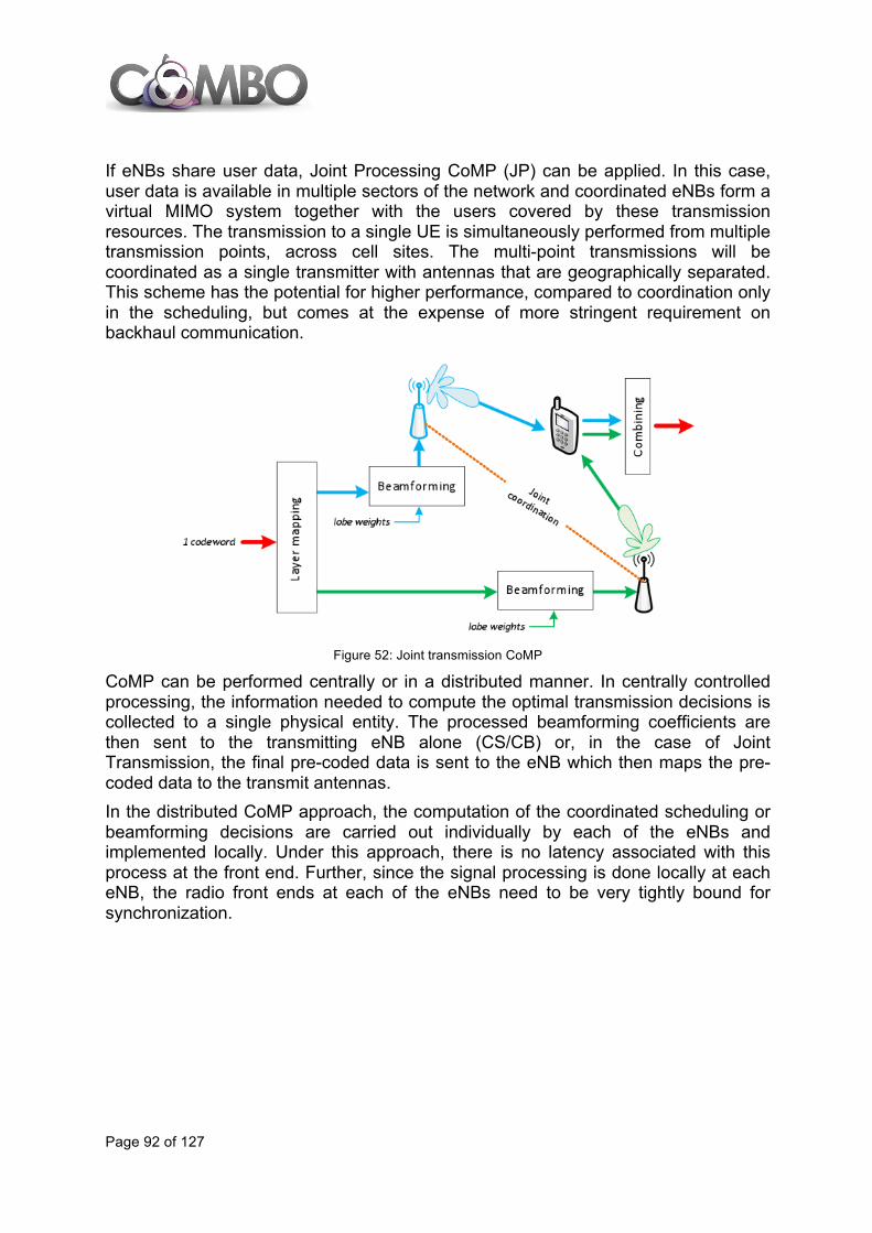
Page 92 of 127
If eNBs share user data, Joint Processing CoMP (JP) can be applied. In this case, user data is available in multiple sectors of the network and coordinated eNBs form a virtual MIMO system together with the users covered by these transmission resources. The transmission to a single UE is simultaneously performed from multiple transmission points, across cell sites. The multi-point transmissions will be coordinated as a single transmitter with antennas that are geographically separated. This scheme has the potential for higher performance, compared to coordination only in the scheduling, but comes at the expense of more stringent requirement on backhaul communication.
Figure 52: Joint transmission CoMP
CoMP can be performed centrally or in a distributed manner. In centrally controlled processing, the information needed to compute the optimal transmission decisions is collected to a single physical entity. The processed beamforming coefficients are then sent to the transmitting eNB alone (CS/CB) or, in the case of Joint Transmission, the final pre-coded data is sent to the eNB which then maps the pre-coded data to the transmit antennas. In the distributed CoMP approach, the computation of the coordinated scheduling or beamforming decisions are carried out individually by each of the eNBs and implemented locally. Under this approach, there is no latency associated with this process at the front end. Further, since the signal processing is done locally at each eNB, the radio front ends at each of the eNBs need to be very tightly bound for synchronization.

Page 93 of 127
Figure 53: Central and distributed CoMP processing
CoMP requires additional signalling overhead on the air interface and over the backhaul in case of intersite cooperation. Therefore, in practice only a limited number of base stations can cooperate in order to keep the overhead manageable. The real performance of some CoMP technologies depends on traffic load and Signal to Interference plus Noise Ratio (SINR). It has to be taken into account that the transmission of CQI information over real X2 interfaces introduces quantification errors, delays and increases the ACK/NACK RTT, which could impact the technology performance. A lot of 3GPP studies are being conducted in Release 12 in order to assess the limitations of CoMP in real scenarios with sub-optimal X2 interfaces. At the same time, significant efforts are currently being put for compensation of the delays incurred by these interfaces in order to exploit legacy IP connections for Joint Transmission schemes.
5.2.2 Heterogeneous networks
5.2.2.1 Heterogeneous network definitions and types A heterogeneous network (sometimes referred as HetNet) is a RAN which comprises different Radio Access Technologies (RAT). These radio technologies could be 3GPP technologies (e.g. UMTS/HSPA, LTE) or IEEE technologies (e.g. IEEE 802.11 Wi-Fi). Additionally, different types of base stations are typically considered, from traditional large macro cells to small cells (SC’s) like micro, pico and femto cells. However, from the user equipment perspective, and in particular from the point of view of the user experience, the heterogeneous network must perform as a single network, hiding any complexity and providing the best possible service. As a matter of fact, current mobile networks are already heterogeneous, as in the same geographical area usually some kind of RAT, for example 2G networks and a 3GPP RAT like UMTS/HSPA, coexist. Such combinations of networks are true heterogeneous networks, taking into account procedures like inter-frequency and
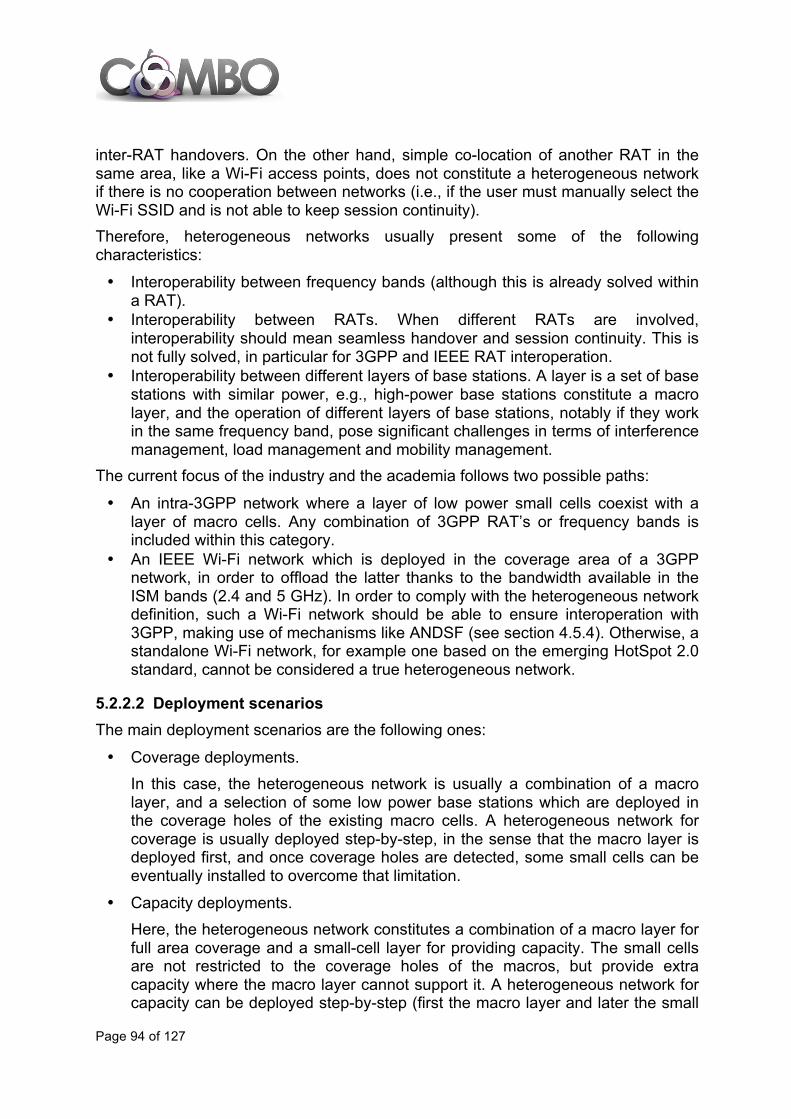
Page 94 of 127
inter-RAT handovers. On the other hand, simple co-location of another RAT in the same area, like a Wi-Fi access points, does not constitute a heterogeneous network if there is no cooperation between networks (i.e., if the user must manually select the Wi-Fi SSID and is not able to keep session continuity). Therefore, heterogeneous networks usually present some of the following characteristics:
• Interoperability between frequency bands (although this is already solved within a RAT).
• Interoperability between RATs. When different RATs are involved, interoperability should mean seamless handover and session continuity. This is not fully solved, in particular for 3GPP and IEEE RAT interoperation.
• Interoperability between different layers of base stations. A layer is a set of base stations with similar power, e.g., high-power base stations constitute a macro layer, and the operation of different layers of base stations, notably if they work in the same frequency band, pose significant challenges in terms of interference management, load management and mobility management.
The current focus of the industry and the academia follows two possible paths:
• An intra-3GPP network where a layer of low power small cells coexist with a layer of macro cells. Any combination of 3GPP RAT’s or frequency bands is included within this category.
• An IEEE Wi-Fi network which is deployed in the coverage area of a 3GPP network, in order to offload the latter thanks to the bandwidth available in the ISM bands (2.4 and 5 GHz). In order to comply with the heterogeneous network definition, such a Wi-Fi network should be able to ensure interoperation with 3GPP, making use of mechanisms like ANDSF (see section 4.5.4). Otherwise, a standalone Wi-Fi network, for example one based on the emerging HotSpot 2.0 standard, cannot be considered a true heterogeneous network.
5.2.2.2 Deployment scenarios The main deployment scenarios are the following ones:
• Coverage deployments. In this case, the heterogeneous network is usually a combination of a macro layer, and a selection of some low power base stations which are deployed in the coverage holes of the existing macro cells. A heterogeneous network for coverage is usually deployed step-by-step, in the sense that the macro layer is deployed first, and once coverage holes are detected, some small cells can be eventually installed to overcome that limitation.
• Capacity deployments. Here, the heterogeneous network constitutes a combination of a macro layer for full area coverage and a small-cell layer for providing capacity. The small cells are not restricted to the coverage holes of the macros, but provide extra capacity where the macro layer cannot support it. A heterogeneous network for capacity can be deployed step-by-step (first the macro layer and later the small

Page 95 of 127
cell layer) or by deploying the macro layer and the small cell layer in a single step. Currently, the usual approach is the former, because traffic demand does not usually require a full heterogeneous network deployment from the beginning of the deployment.
• Hot spot deployments The goal of a hot spot deployment is also improving capacity, but compared with the previous case the target area is limited to specific places where traffic demand has already been detected as high (and in this case deployment will be made step-by-step) or where it is expected to increase in the next future. Typical examples are shopping malls, business areas, sport stadiums or communications hubs. Hot spots deployments can be tackled by means of 3GPP-only small cells, but they are the most typical example of a 3GPP / IEEE heterogeneous network, because Wi-Fi access points are widely used in these environments for Wi-Fi offloading. Although current Wi-Fi hot spot deployments are uncoordinated with the 3GPP layer, and thus do not constitute true heterogeneous network, emerging solutions like 3GPP’s ANDSF can improve the interoperation of both types of technologies.
5.2.2.3 Interworking with EPC Cellular networks are moving towards a convergence scenario where a unique core network solution provides IP-based services over multiple Radio Access Technologies (Multi-RATs). The 3GPP architecture-related activity is split into two basic directions, namely, GPRS enhancements for E-UTRAN access [92] and architecture enhancements for non-3GPP access [93]. This second direction defines the interworking functions and procedures in heterogeneous environment with non-3GPP access networks for both trusted (e.g. eHRPD, WiMAX) and untrusted (e.g. public WLANs) access. The mobility functionality in this case is mainly based on IETF protocols. In particular, the network-based mobility protocol Proxy Mobile IPv6 (PMIPv6) [94] and the client-based mobility protocols such as Dual-Stack Mobile IPv6 (DSMIPv6) [95] and Mobile IPv4 (MIPv4) [96] are used for this purpose. Subsequently, GTP-based procedures were also included in the specification [93].

Page 96 of 127
Figure 54: EPS mobility architecture in heterogeneous networks
The simplified EPS network architecture to support mobile services over heterogeneous access networks is illustrated in Figure 54. The Packet Data Network Gateway (PDN-GW) is considered as a stable IP anchor point to support seamless mobility of the UE in heterogeneous environment. That is, the IP address of the UE is not changed when it moves from one access to another. The Serving Gateway (S-GW) acts as the default router for the UE in 3GPP access [97]. The Access Gateway (A-GW) serves as the S-GW in case of trusted non-3GPP access networks. In case of untrusted non-3GPP access the evolved Packet Data Gateway (ePDG) plays the role of the S-GW. Note that EPS supports the client-based DSMIPv6 and MIPv4 only over non-3GPP access. Over 3GPP access client-based mobility is not used. It is always assumed that the 3GPP access is the “home link”, in the host-based Mobile IP sense [89]. Over non-3GPP access, it is also possible to use network-based PMIPv6. For 3GPP access, only network-based mobility protocols are used; either GTP or PMIPv6 [89]. 3GPP Release 8 has defined an additional entity (not shown in the figure) called Access Network Discovery and Selection Function (ANDSF) that is responsible for access network discovery and operator intersystem mobility policies [97]. Note that in 3GPP Release 8 the end-user cannot communicate using multiple access towards a PDN network. This capability was defined in 3GPP Release 10 that motivates the development of IP flow mobility concept [100] between different access systems. A restriction is that only a single non-3GPP access can be involved [100]. To support this feature the ANDSF framework should be enhanced with the introduction of Inter System Routing Policies (ISRP). This system should allow the MNO to indicate preferred or forbidden access network based on the PDN identifier (APN), the destination IP address, the destination port or a combination of these parameters [101].

Page 97 of 127
5.3 Fixed infrastructure evolution of mobile networks
5.3.1 Mobile backhaul evolution
5.3.1.1 Global mobile backhaul evolution The mobile backhaul evolution is mainly driven by the mobile traffic growth and by technology improvements such as for example replacement of TDM and ATM protocols by IP, small cells deployment, C-RAN deployment with fronthaul introduction between RRH and BBU etc. Thus the transport network will require more capacity, flexibility and scalability to support existing and new service offerings. This will lead to an end-to-end IP transformation in both mobile and transport networks:
• RAN migration to Full IP RAN • Mobile backhaul network migration to full IP to increase overall available
bandwidth while reducing the overall cost • Support direct connectivity between edge nodes of the mobile backhaul
architecture as the global architecture goes flat (i.e. less equipment hierarchy in the network to support X2 interfaces for example).
• Deployment of C-RAN with fronthaul solutions (see section 5.3.4) • Migration to Seamless L3VPN in the mobile backhaul network.
5.3.1.2 Transport IP evolution With LTE and LTE-A as drivers, the backhaul transport solution should be as flexible as possible allowing a global flexibility of the network such as eNodeB auto-configuration through a full IP network but also EPC equipment relocation (or distribution) and network reorganization. It may also ease new models to emerge (internet offload, content delivery distribution). With such objectives, a seamless L3VPN transport solution appears as a serious option to consider for LTE and LTE-A.
Figure 55: Starting point: IP RAN + L3 VPN based Mobile Backhaul
With packet based access, even legacy services can be mapped onto the Ethernet layer using MPLS pseudowires or circuit emulation techniques. Thus legacy technologies and 2G IP, 3G IP and LTE traffic can be conveyed through L2VPN or L3VPN in the access and aggregation network. Figure 56 shows a combined backhaul supporting 2G/3G/LTE interfaces deployed over full IP packet transport network in a seamless L3VPN IP transport starting from the first aggregation level toward the core network.
Page 98 of 127
Figure 56: Mobile backhaul objective: Seamless L3VPN
5.3.2 Mobile fronthaul evolution The need for more capacity pushes operators to increase the cell site throughput through a number of potentially combined measures. This includes increasing the density of macro cell sites where applicable, increasing the capabilities of existing macro cell sites (e.g., additional radio frequency bands, additional sectors, MIMO, beam forming, etc.), and deploying small cells within a macro area. Combinations of these approaches can result in heterogeneous networks. Heterogeneous networks result in a radio environment prone to considerable interference. The most effective means to mitigate that is through combined baseband processing of the interfering cell radio signals. This, in turn, favours a centralization of baseband processing, implying the extension in length of the connectivity between Baseband Unit (BBU) and Remote Radio Unit (RRU). Currently, this connectivity is local to cell site and based on TDM protocols such as Common Public Radio Interface (CPRI) and Open Base Station Architecture (OBSAI). However, the predominant deployment of CPRI and the specific interest to this frame format by vendors and operators engaged in defining solutions for centralization make it the preferred option. In addition, TDM-based solutions have the advantage of ridding sites from more complex packet switching equipment and functions, The continuous efforts for optimizing the CapEx and OpEx in the end-to-end mobile network, are expected to result in two different network models to be used for the interconnection between heterogeneous networks and gateways/IP edge at CO (see Figure 67):
• Conventional packet backhauling: where baseband signals are processed at the cell site by a local BBU. Packet-based backhauling is then used for the BBU.
• CPRI fronthauling: where BBUs are placed in a remote location (e.g., in an existing macro site or co-located with a CO), leaving only the radio parts, antennas and RRUs, at the cell sites.

Page 99 of 127
Figure 57 Simplified view of mobile fronthaul / backhaul network and associated components
In both packet backhauling and CPRI fronthauling, the Cell Site Gateway (CSG), located in or close to the macro cell site, performs a first level of aggregation on traffic coming from RRUs (2G, 3G, LTE) and the needed adaptation functions towards the common multi-layer fronthaul / backhaul network. In CPRI fronthauling, an equivalent functional block is assumed to be equipped also at the CO, in order to allow the appropriate CPRI multiplexing/demultiplexing operations. Assuming no radio interference coordination, requirements on throughput, latency and jitter are relatively low for packet backhauling (hundreds of Mb/s for LTE cell sites) compared to CPRI. The IP CSG is, then, designed to provide a seamless interoperation with converged L1/L2/L3 backhaul networks and radio controllers (BSC, RNC, S-GW placed at CO). However, the need for coordination, e.g., CoMP, may put challenging requirements on the backhaul in the case of distributed baseband processing and packet backhauling. CPRI fronthaul model implies the collection of serial CPRI streams at cell sites, where the sampled antenna signals (I/Q data) related to different mobile technologies (including 2G, 3G, LTE) are mapped into TDM time slots of a CPRI frame. The result is a constant bit rate signal with line rates in the range of 614.4 Mb/s and 10.137 Gb/s. Current requirements for CPRI interface, in terms of line rate (multi-Gb/s) and maximum delay budget associated to the transport network (typically lower than a few hundreds of µs) impact the selection of transport options, so that xDSL copper and TDMA PON (XGPON) fibre do not appear as suitable technologies, mainly due to the delay constraint (from 1 to 3 ms). Thus, although microwave can reach multi-Gb/s data rates and satisfy CPRI requirements, the main option for CPRI transport is
Corenetwork
CPRI CSG
NGPOP
IP Edge
BBUhotel
S-GWP-GW
BBU-‐ ETH-‐ IPoETH
Macro Cell
Macro Cell
Small Cell
RRU
ETH
CPRI
CPRI
Multi-‐layerFronthaul / Backhaul
Network
-‐ ETH-‐ TDM
Network Edge
Network Edge
Network Edge
IP CSG*
Mobile fronthaul NE
CPRI MX/DMX**
* BBU/RRU & IP/CPRI CSG possibly co-‐located
** CPRIMX/DMX and Network Edge node possibly integrated
Cabinet
Access AggregationUEHNB Core

Page 100 of 127
that based on fibre. As depicted in Figure 58 the simplest network architecture option in a fibre-rich context is obtained by deploying point-to-point fibre connections between RRUs and BBUs across the fronthauling area expected to span typically up to 20 km (40 km or 60 km are values sometimes considered as possible max span length, but still to be agreed by the technical community)). An alternative approach implies, multiplexing of several CPRI streams over the same physical medium, either via WDM (optical) or via TDM (electronic) devices. Different topologies for the interconnection RRUs-BBUs may be addressed (point-to-point, tree, ring).
Figure 58 Basic alternatives for CPRI fronthauling
WDM multiplexing implies that coloured optical modules are equipped within the RRUs (and BBUs), and multiplexing is performed via mux/demux (or OADM) filters operating as CPRI CSG (thus, purely passive CSG). In a possible variant of this option, both coloured optical interfaces and WDM multiplexer are equipped in a small box again located nearby the cell site. CWDM (defined by ITU-T G.694.2 recommendation) or DWDM (defined by ITU-T G.694.1 recommendation) grid usage depends on the amount of client signals to be multiplexed. WDM-based solutions show the basic advantage of no need of power supply and quite easy installation of CSG (which is based on passive optical filters). But the support of a service demarcation function (see carrier grade OAM), specifically needed when the fronthaul network is owned by an operator different than mobile (see a transport operator), requires specific means to be developed (e.g. smart optical modules able to terminate monitoring tools run by transport operator) and agreement on the domains boundary definition. TDM multiplexing in the access implies that a small electronic box (active) has to be located in the cell site, in place of BBUs. Possible options for multiplexing function may be:
• Multiplexing in the CPRI domain, by aggregating client CPRIs with operative rate in the range of 614 Mb/s – 6.144 Mb/s (Rate 1 to Rate 6 of the CPRI hierarchy) into one CPRI 10.137Gb/s link (Rate 8 and upper bound of the CPRI hierarchy);
• Encapsulating client CPRIs in Low Order ODU0/flex digital containers, then multiplexing them into one High Order ODU2 digital container (according to ITU-T G.709 OTN hierarchy rules).
A TDM-based solution allows, in principle, to better fill the line interface operating at a defined rate on a single wavelength (1310 nm or 1550 nm). But, when the aggregated signal exceeds this rate (e.g. 10G), more line interfaces, then, more fiber
P2PTREERING
P2P fibers RRH-BBU CPRI multiplexingRRHs
BBUs BBUsRRHs
WDMTDM
WDMTDM
CPRI CSG

Page 101 of 127
uplinks are needed. In alternative, an higher rate uplink (e.g. 40G) has to be deployed.. A combined TDM (e.g. OTN)+WDM solution may allow, then, overcoming the scalability issue of pure TDM solutions by minimizing the amount of needed fibres (thanks to WDM), while still leveraging on carrier-grade OAM, resilience and management functions.
5.3.3 Synchronization Synchronization is an essential component of the mobile network infrastructure since base stations that support 2G, 3G and/or 4G all have requirements relating to one or more of the following parameters:
• Frequency: here the rate at which “significant instants” or “events” (clock ‘ticks’, symbols arriving per unit time) occur is the important parameter. The instants need not occur at the same moment at different nodes, but the rate of occurrence should be the same. Note: Frequency synchronization is also known as syntonization.
Figure 59 Frequency Synchronisation
• Phase: phase synchronization implies that all associated nodes have access to timing signals whose significant events occur at the same instant (within the relevant phase accuracy requirement) [102]. This implies that the delays between the common source or reference node and each of the slave nodes be compensated for. The actual time at which the significant events occur is not important, but that the events occur at the same instant at each node in the synchronised network is. Note: sometimes referred to as “System Specific Time”.
Figure 60 Phase Synchronisation
• Time: this can be regarded as a special case of phase synchronisation, in which the actual time (relative to some specified reference) of each significant event is now important.

Page 102 of 127
Figure 61 Time Synchronisation
Historically, 2G and 3G base stations operated in a FDD mode, the other operating in the upstream direction. Each channel and each base station needs to be carefully controlled around a stable carrier frequency in order to avoid interference from neighbouring bases stations which ultimately leads to dropped calls. In order to maintain a stable operating frequency, legacy base stations originally relied on the inherent synchronization capability of the backhaul network, which was then Time-division Multiplex (TDM)-based to derive a stable frequency signal, in the form of an E1/T1 signal which operates at 2.048 Mb/s or 1.544 Mb/s respectively. The E1/T1 interfaces within the backhaul network were generally locked to a Primary Reference Clock (PRC) deeper in the network via the Plesiochronous Digital Hierarchy (PDH) or Synchronous Digital Hierarchy (SDH) core network. As mobile air interfaces adapted to support increasing bandwidth and data rates, the goal to optimise the air interface and reduce spectrum requirements lead to the migration towards simplex antenna concepts which use a single radio channel and providing uplink and downstream time slots rather than multiple radio channels. TDD operation as it is also known, is based around the concept of timeslots and relies on base stations operating in the network which have a common phase or time reference. Note that in this context, phase and time alignment are closely related. Phase alignment implies that the significant instance of each base station is referenced to a common source, whereas time alignment implies that each base station is locked to a common absolute time source such as Coordinated Universal Time (UTC). Methods used to distribute Phase and Time of Day to base stations have ranged from the use of Global Positioning Systems (GPS) to the more recently adopted Precision Time Protocol (PTP), IEEE standard 1588-2008 (often referred to as 1588v2). GPS alone is neither scalable nor resilient to vulnerabilities (such as GPS jamming). Therefore the preference has been to deploy multiple synchronization delivery methods within the backhaul network. Synchronization requirements for the various air interfaces are shown in Table 6:
Technology Frequency Phase/Time
3GPP UMTS & LTE FDD
50 ppb Wide area
100 ppb Med/local
250 ppb Home, as defined in
None
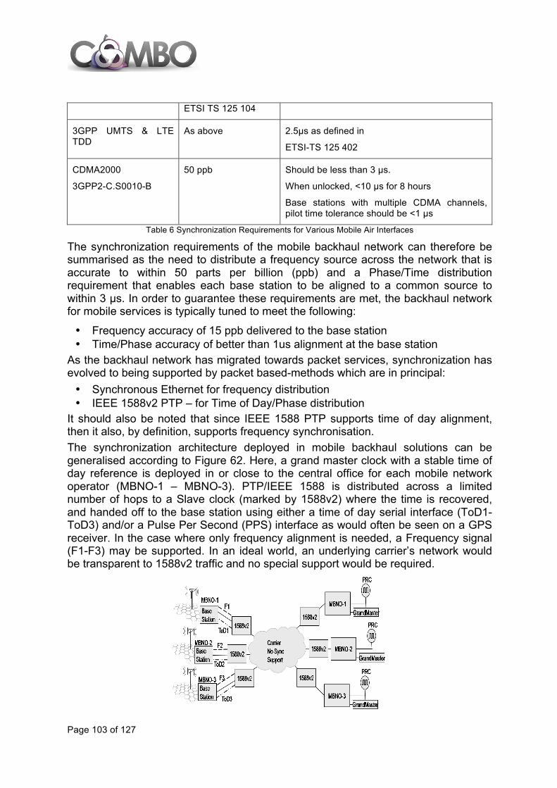
Page 103 of 127
ETSI TS 125 104
3GPP UMTS & LTE TDD
As above 2.5µs as defined in
ETSI-TS 125 402
CDMA2000
3GPP2-C.S0010-B
50 ppb Should be less than 3 µs.
When unlocked, <10 µs for 8 hours
Base stations with multiple CDMA channels, pilot time tolerance should be <1 µs
Table 6 Synchronization Requirements for Various Mobile Air Interfaces
The synchronization requirements of the mobile backhaul network can therefore be summarised as the need to distribute a frequency source across the network that is accurate to within 50 parts per billion (ppb) and a Phase/Time distribution requirement that enables each base station to be aligned to a common source to within 3 µs. In order to guarantee these requirements are met, the backhaul network for mobile services is typically tuned to meet the following:
• Frequency accuracy of 15 ppb delivered to the base station • Time/Phase accuracy of better than 1us alignment at the base station
As the backhaul network has migrated towards packet services, synchronization has evolved to being supported by packet based-methods which are in principal: • Synchronous Ethernet for frequency distribution • IEEE 1588v2 PTP – for Time of Day/Phase distribution
It should also be noted that since IEEE 1588 PTP supports time of day alignment, then it also, by definition, supports frequency synchronisation. The synchronization architecture deployed in mobile backhaul solutions can be generalised according to Figure 62. Here, a grand master clock with a stable time of day reference is deployed in or close to the central office for each mobile network operator (MBNO-1 – MBNO-3). PTP/IEEE 1588 is distributed across a limited number of hops to a Slave clock (marked by 1588v2) where the time is recovered, and handed off to the base station using either a time of day serial interface (ToD1-ToD3) and/or a Pulse Per Second (PPS) interface as would often be seen on a GPS receiver. In the case where only frequency alignment is needed, a Frequency signal (F1-F3) may be supported. In an ideal world, an underlying carrier’s network would be transparent to 1588v2 traffic and no special support would be required.

Page 104 of 127
Figure 62 Transport of Time/Frequency using 1588v2- Desired Goal
Although, in theory, PTP/1588v2 can be operated across a network without any underlying support for the protocol (that is with no on-path support), it is widely acknowledged that some level of on-path support may be needed in order to future proof the synchronization service over all potential use cases of the network (see next figure). Since PTP/IEEE1588v2 is susceptible to Packet Delay Variation (PDV), mitigation solutions such as Boundary Clock and Transparent Clock are now considered as being required in the network (denoted by white boxes with 1588v2 label, in the cloud in the figure below) in order to guarantee that the desired frequency and time accuracy can be met under all potential network use scenarios.
Figure 63 Transport of Time/Frequency using 1588v2- Realistic/Future Proof Architecture
Evolution topics in relation to synchronization and the backhaul network for mobile services could include: • More demanding accuracy requirements driving accuracy from 1 µs to 500 ns
and lower. - For new air interfaces/services (packing more channels into given spectrum)
optimisation of air interface. - Improved support for Coordinated Multipoint operation. - Location based services.
• Improved PTP standards implying different operation compared to currently available devices. - Improvements to transparent clock device – currently under discussion in
IEEE 1588v3. • Changes in the deployment scenarios and positioning of Grandmaster Clocks
(GM). - Placement of smaller GMs close to the edge of the network might reduce the
need for on-path support. - Multi-operator scenarios:
§ Synchronisation as a service. § Synchronisation transport as a service.

Page 105 of 127
• Hybrid Synchronisation architectures combining packet based methods (IEEE1588v2) with physical layer frequency transport (Synchronous Ethernet). - Improved performance including improved start-up and holdover and
resilience. • Synchronization as a Service changes the operational model.
- As more mobile operators request synchronization services from carriers, the carrier starts to sell the synchronization feed as a service.
- Need to define a SLA for the synchronization service implies monitoring, fault finding, etc.
• Adoption of FMC causes changing/more demanding traffic mix in backhaul path. - Standards and clock recovery algorithms need to reflect the increased
complexity of the path characteristics. • Synchronisation in non-mobile backhaul applications.
- Business services and financial trading requesting improved accuracy. - Specialist networks such as industrial control and smart grid, etc. - QoS/Performance monitoring functions such as TWAMP/Y.1731 are trending
towards improved time accuracy (microsecond level), likely to need specialist time distribution methods to achieve this.
• Improvements in GNSS (Global Navigation Satellite System) technology, for example the ESA Galileo program, now scheduled to be fully operational by 2020, and next generation GPS.
• Continued developments in clock device technology which may relax requirements for synchronisation network performance for some applications. - “Chip Scale Atomic Clock” (CSAC) technology already available able to
achieve ±5.0E-11 accuracy at shipment.
5.3.4 Cloud RAN The term C-RAN was created by the China Mobile Research Institute [102], [104]. In this term, the letter C stands for Centralization (of Base Band Units, BBUs), Co-operative (radio with distributed antennas), Cloud (infrastructure RAN), and Clean (target system, in the sense of energy consumption). Often, this is abbreviated as Cloud RAN, but the original idea included the aspects of centralization, co-operative multi-point radio and clean systems equally. The basis of C-RAN is the separation of the eNB (the base station node in LTE) into a BBU and an RRU (Remote Radio Unit, a.k.a. RRH, Remote Radio Head). This separation results in a new section in the mobile network architecture called fronthaul, i.e., the network section between the RRU and BBU. The separation of the base station can be done to different degrees (i.e., including or not including the complete baseband processing), and with different distances between RRU and BBU, see Figure 64.
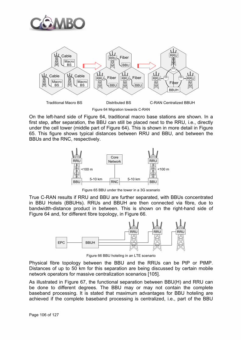
Page 106 of 127
Figure 64 Migration towards C-RAN
On the left-hand side of Figure 64, traditional macro base stations are shown. In a first step, after separation, the BBU can still be placed next to the RRU, i.e., directly under the cell tower (middle part of Figure 64). This is shown in more detail in Figure 65. This figure shows typical distances between RRU and BBU, and between the BBUs and the RNC, respectively.
Figure 65 BBU under the tower in a 3G scenario
True C-RAN results if RRU and BBU are further separated, with BBUs concentrated in BBU Hotels (BBUHs). RRUs and BBUH are then connected via fibre, due to bandwidth-distance product in between. This is shown on the right-hand side of Figure 64 and, for different fibre topology, in Figure 66.
Figure 66 BBU hoteling in an LTE scenario
Physical fibre topology between the BBU and the RRUs can be PtP or PtMP. Distances of up to 50 km for this separation are being discussed by certain mobile network operators for massive centralization scenarios [105]. As illustrated in Figure 67, the functional separation between BBU(H) and RRU can be done to different degrees. The BBU may or may not contain the complete baseband processing. It is stated that maximum advantages for BBU hoteling are achieved if the complete baseband processing is centralized, i.e., part of the BBU
C-RAN Centralized BBUH
Cable
MacroBS
MacroBS
MacroBS
CableCable
BBU
FiberRRU
BBU
FiberRRU
BBU
FiberRRU
RRU RRUFiber
RRU
BBUH
Traditional Macro BS Distributed BS
<100 m
5-10 km
CoreNetwork
RNC
RRU
BBU
RRU
BBU
<100 m
5-10 km
RRU
BBUHEPC
RRU RRU
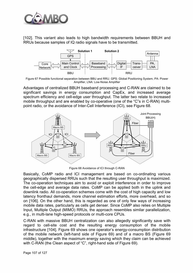
Page 107 of 127
[102]. This variant also leads to high bandwidth requirements between BBUH and RRUs because samples of IQ radio signals have to be transmitted.
Figure 67 Possible functional separation between BBU and RRU. GPS: Global Positioning System, PA: Power
Amplifier, LNA: Low-Noise Amplifier
Advantages of centralized BBUH baseband processing and C-RAN are claimed to be significant savings in energy consumption and CapEx, and increased average spectrum efficiency and cell-edge user throughput. The latter two relate to increased mobile throughput and are enabled by co-operative (one of the “C”s in C-RAN) multi-point radio, or the avoidance of Inter-Cell Interference (ICI), see Figure 68.
Figure 68 Avoidance of ICI through C-RAN
Basically, CoMP radio and ICI management are based on co-ordinating various geographically dispersed RRUs such that the resulting user throughput is maximized. The co-operation techniques aim to avoid or exploit interference in order to improve the cell-edge and average data rates. CoMP can be applied both in the uplink and downlink radio. All co-operation schemes come with the cost of high capacity and low latency fronthaul demands, more channel estimation efforts, more overhead, and so on [106]. On the other hand, this is regarded as one of only few ways of increasing mobile data rates, particularly as cells get denser. Since CoMP also relies on Multiple Input, Multiple Output (MIMO) RRUs, the approach resembles similar parallelization, e.g., in multi-lane high-speed protocols or multi-core CPUs. C-RAN with massive BBUH centralization can also allegedly significantly save with regard to cell-site cost and the resulting energy consumption of the mobile infrastructure [104]. Figure 69 shows one operator’s energy-consumption distribution of the mobile network (left-hand side of Figure 69) and of a macro BS (Figure 69 middle), together with the maximum energy saving which they claim can be achieved with C-RAN (the Clean aspect of “C”, right-hand side of Figure 69).
BBU
Main Controland Clock
CoreNetwork
GPS
BasebandProcessing
DigitalIF
… Trans-ceiver
… PA,LNA
…Antenna
RRU
Solution 1 Solution 2
ICI
Fiber
Fiber
BBU(H)Joint Processing
Macro BS
RRU RRU
RRU
Macro BS
Macro BS
ICI
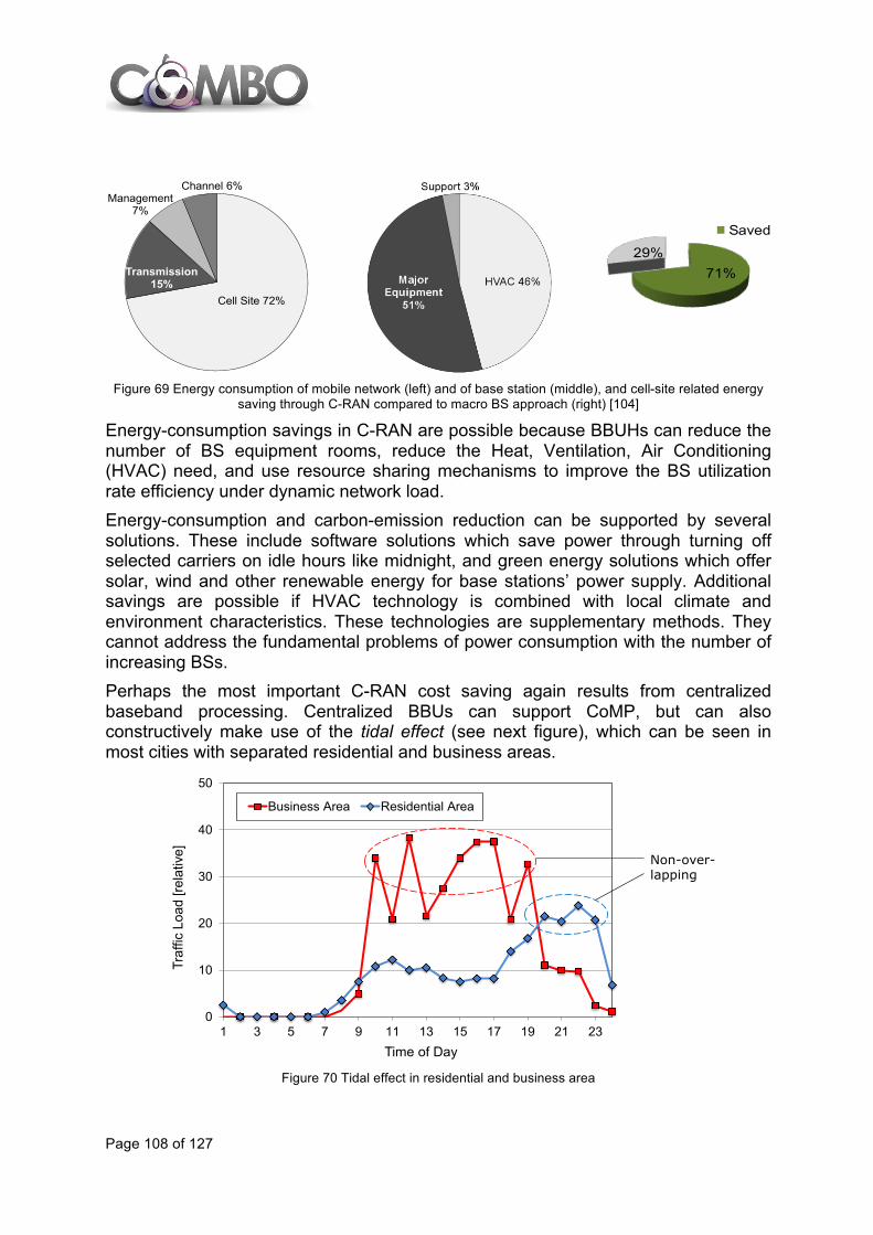
Page 108 of 127
Figure 69 Energy consumption of mobile network (left) and of base station (middle), and cell-site related energy
saving through C-RAN compared to macro BS approach (right) [104]
Energy-consumption savings in C-RAN are possible because BBUHs can reduce the number of BS equipment rooms, reduce the Heat, Ventilation, Air Conditioning (HVAC) need, and use resource sharing mechanisms to improve the BS utilization rate efficiency under dynamic network load. Energy-consumption and carbon-emission reduction can be supported by several solutions. These include software solutions which save power through turning off selected carriers on idle hours like midnight, and green energy solutions which offer solar, wind and other renewable energy for base stations’ power supply. Additional savings are possible if HVAC technology is combined with local climate and environment characteristics. These technologies are supplementary methods. They cannot address the fundamental problems of power consumption with the number of increasing BSs. Perhaps the most important C-RAN cost saving again results from centralized baseband processing. Centralized BBUs can support CoMP, but can also constructively make use of the tidal effect (see next figure), which can be seen in most cities with separated residential and business areas.
Figure 70 Tidal effect in residential and business area
Cell Site 72%
Transmission 15%
Management 7%
Channel 6%
71%29%
Saved
0
10
20
30
40
50
1 3 5 7 9 11 13 15 17 19 21 23
Traf
fic L
oad
[rela
tive]
Time of Day
Business Area Residential Area
Non-over-lapping

Page 109 of 127
The tidal effect describes the movement of the local area with highest mobile traffic demands within a city of reasonably large size over day time. Typically, traffic is highest over the day in business areas, whereas it is higher in the evening in residential areas. In time, the traffic peaks in these different areas are non-overlapping. Without centralized BBUs, processing in both areas must be designed such that daily peaks can be served. With massive baseband pooling, a single BBUH can be used to serve both areas (at different time of day), thus enabling significant CapEx savings in total baseband processing. In Figure 71 we can see a simplified view of the mobile network architecture. On the left-hand side, (MIMO) RRHs serve the mobile client equipment. The RRHs are connected via the C-RAN to the BBUs, which are clustered in a BBUH. The BBUH is connected via the 3GPP S1 interface to the S-GW and the MME. Similar interfaces and functions can be identified for 3G UMTS and 2G/2.5G GSM/GPRS.
Figure 71 C-RAN as part of the complete mobile infrastructure
With BBUH clustering, synchronization via the X2 interface is required only inside the BBUH. Only when users change BBUH areas, synchronization is required via S1. Thus, the amount of synchronization external to the BBUs is reduced. On the other hand, the fronthaul requires low latency, and high data rates. Both are supported by the CPRI protocol. Typically, the RTT delay for the CPRI transport is restricted to <<1 millisecond [107]. Finally, the C-RAN architecture is not restricted to LTE or LTE-Advanced. Separation of the macro BSs into BBUs and RRUs is possible also for 2G/2.5G GSM/GPRS and 3G UMTS. This allows, over time, migration of several mobile generations (given older generations are not switched off) onto a common C-RAN and GERAN/UTRAN/e-UTRAN architecture. This can be achieved in cases where the BSs of older mobile generations are replaced by newer equipment.
5.4 Network management evolution
5.4.1 Self-organizing Networks This section deals with the aspects of a self-organizing network (SON) [128], [129]. The SON functionality includes all possible technical functions that a network
Core Network
Fronthaul
S-GW
EPCRRH
MMES1
S1P-GW
S5S11
PCRF
S7P/I/S-CSCF
SGi
Rx+
MGCF
MGWIMS
WLANetc.
S2
ExternalPacketNetworks
ExternalCircuitNetworks
BBUH
BBU
BBU
X2
RRH
Backhaul
CPRI
CPRI
Radio Access Network

Page 110 of 127
manages in an autonomous way. SON follows two objectives: excellent network performance and operational efficiency. This is a natural consequence because complexity and heterogeneity of future radio access networks will dramatically increase, and operational tasks such as network planning, deployment, OAM functionalities, network optimization, etc. will increase accordingly.
5.4.1.1 SON definition and self-x functionalities A self-organizing network (SON) is a communication network which supports self-x functionalities, e.g., self-configuration or self-optimization. Self-x enables the automation of operational tasks, and thus it minimizes human intervention. Generally self-x functionalities are based on a loop (self-x cycle) of gathering input data, processing these data and deriving optimized parameterization (see Figure 72).
Figure 72: Basic self-x cycle
Furthermore, self-x effectuates the improvement of the usability of future mobile radio access solutions (“plug&play”), and it accelerates the introduction and deployment of new services. In addition, self-organizing approaches may contribute to further increasing spectral efficiency, since they can be used to allocate capacity where it is needed. Finally, self-x approaches target also on improvement of Quality of Service (QoS) perceived by the user. Besides the increase of spectral efficiency, this is also the optimization of interference and coverage in critical reception conditions. Hence, the main gains of self-x are expected first of all in OpEx reductions and secondly in network performance improvements. From an operator’s point of view, the SON features with high priority especially during the initial stage of deployment of a new network are: • HW & SW installation, Network authentication: with significant OpEx implication
through optimized factory pre-configuration, number of site visits, manual configuration, etc.
Actual NetworkParameters
NetworkMonitoring
New Network Parameters
ParameterConfiguration Optimization
Self-x
SON
cycle
Actual NetworkParameters
NetworkMonitoring
New Network Parameters
ParameterConfiguration Optimization
Self-x
SON
cycle

Page 111 of 127
• Radio parameters setup: some self-configuration functionalities such as Automatic Neighbour Relation (ANR), Neighbour Cell List (NCL), Physical Cell Identity (PhyCID), etc. This is important to get the mobile radio network functional with minimized OpEx.
• Radio parameter optimization and energy saving: power optimization (interference reduction, energy saving, TX power optimization, antenna tilt), handover optimization, load balancing, coverage and capacity optimization, etc.
SON is considered along its different manifestations addressed as self-x:
• Self-configuration: Self-configuration process is defined as the process where newly deployed nodes are configured by automatic installation procedures to get the necessary basic configuration for system operation.
• Self-planning: Self-planning could be considered as a particular situation of the self-configuration mechanisms. It comprises the processes were radio planning parameters are assigned to a newly deployed network node. Parameters in scope of self-planning are, e.g., neighbour cell relations, max TX power values of UE and eNodeB, and handover parameters.
• Self-optimization: Self-optimization is defined as the process where UE and base station measurements and performance measurements are used to auto-tune the network.
• Self-managing: Self-managing is the automation of OAM tasks and workflows, i.e., shifting them from human operators to the mobile networks and their network elements.
• Self-healing: Self-healing is a SON functionality which detects problems itself and solves or mitigates these problems to avoid user impact and to significantly reduce maintenance costs.
5.4.1.2 SON status and evolution within NGMN, 3GPP, and several R&D projects
Self-organizing network are currently under research and development in different organizations and research and development projects. Some of the most representative are:
• Next Generation Mobile Networks (NGMN) • 3GPP • R&D – E3 (FP7; Duration: 1/2008 - 12/2009) • R&D – SOCRATES (FP7; Duration: 1/2008 - 12/2010) • R&D – BeFEMTO (FP7; Duration: 01/2010 - 06/2012) • R&D – UniverSelf (FP7; Duration: 09/2010 - 08/2013) • R&D – GreenNets (FP7; Duration: 01/2011 - 08/2013) • R&D – SEMAFOUR (FP7; Duration: 09/2012 - 08/2015) • R&D – METIS (FP7; Duration: 11/2012 - 04/2015) • R&/D – SHARING (Celtic-Plus, Duration: 12/2012 - 06/2015)

Page 112 of 127
5.5 Roadmap for mobile evolution 3GPP will continue working on the specification of 3G mobile system and beyond. In the previous sections, the technical specifications released by 3GPP in the previous years have been described [119]. Initial deployments are announced mainly in Asia, based on Release 10 in 2013 and Release 11 frozen in September 20125 (general equipment availability is expected by 2015). 3GPP Release 12 and Release 13 will provide technical solutions beyond 4G to deal with the increasing mobile data volume and user equipment diversity. Some technical issues identified are related to interference coordination and management, new carrier aggregation scenarios, MIMO enhancements, dynamic TDD, enhanced discovery and mobility, small cells frequencies and backhaul, inter-site carrier aggregation, etc. Release 12 stage 1 (service description at service-user point of view) was completed in March 2013 and it is expected to reach stage 3 (protocol implementation at physical interfaces) in June 2014 with commercial equipment becoming available at the end of 2016. Release 13 doesn’t have official dates but it is expected to be finalised in 2016 with commercial availability between 2017 and 2018. Future 3GPP specifications will continue with Release 14 with 5G or 5th generation of mobile networks dealing with the massive growth in connected devices, traffic volume and with a wide range of different requirements and characteristics. Release 14 doesn’t have also an official date for its stages, but the specification could last until 2017 or 2018 with commercial equipment in 2020. FP7 METIS project [88], as commented previously, is working on mobile systems beyond 2020. Wi-Fi interworking with 3GPP is starting to be deployed in different operators where LTE smartphones will be able to roam to Wi-Fi hotspots [120]. Initial deployments will be based on automatic and seamless authentication of smartphone on Wi-Fi hotspots to offload mobile traffic to Wi-Fi networks, but future deployments will try to use Wi-Fi networks as an integrated RAN, allowing to route traffic to the most convenient network (even to use mobile and Wi-Fi networks simultaneously) depending on the current status of the network, the service requested and the user’s QoE. C-RAN solutions have been proposed in the previous years with some existing prototypes to validate the proof of concept; however they will need to evolve in the future. Centralized RAN solutions where radio processing (RRU) and baseband processing (BBU) are separated and BBU are concentrated in BBU hotels are already deployed in Asia (mainly in dense urban areas). However this kind of solutions must progress during the next years in order to interconnect BBUs located at the same BBUH and optimize their performance, provide baseband pooling services and virtualize current solutions using general purpose hardware in a cloud RAN approach.
5 Core network protocols stable December 2012, radio access protocols stable March 2013 - though performance parts of RAN work items may not be complete before June 2013

Page 113 of 127
Figure 73 illustrates the roadmap for the mobile network evolution:
Figure 73 – Roadmap for mobile network evolution

Page 114 of 127
6 CONCLUSIONS This report analyses the main technologies and architectures of fixed and mobile networks that are deployed currently by telecom operators and the most representative evolution trends up to 2020. The main key findings are:
• The main technologies deployed and used currently: customers can access broadband services via fixed and mobile networks. Fixed broadband networks in Europe are currently dominated by DSL access technologies, providing a capacity of tens of Mb/s, with an increasing number of subscribers using FTTH connections where a capacity of several hundreds of Mb/s is common. In addition, HFC networks are relevant, providing so far the same commercial offers than FTTH. Wi-Fi is being used with multiple hotspot architectures such as Community Wi-Fi, business and operator approaches. Microwave is mainly used for the business segment or for mobile backhauling.. In mobile networks, 2G and 3G technologies are widely available in Europe, and in many countries LTE with a capacity of up to 100 Mb/s is commercially available too with an increasing coverage.
• The degree of FMC in current networks: fixed and mobile networks remain mainly independent and FMC is limited to some areas in which fixed networks can be used to connect the base stations to the mobile network elements, such as the mobile backhaul or the fixed IP backbone.
• State of the art in fixed (VDSL2 with vectoring and bonding, DOCSIS 3.0, 10G-EPON, XG-PON1, Wi-Fi IEEE 811.ac, carrier grade Ethernet, MPLS) and mobile networks (LTE and EPC).
• The most relevant lines of evolution in fixed (G.fast, NG-PON2, WDM-PON, LR-PON, Wi-Fi and mobile integration, SDN) and mobile networks (LTE-A, mobile fronthaul, cloud RAN, new offloading and synchronization mechanisms, SON).
• The most interesting technological initiatives dealing with both fixed and mobile networks. Although this deliverable is focused on the independent evolution of fixed and mobile access and aggregation networks, future trends cannot be considered without addressing FMC-oriented efforts done by yet independent technologies. The following FMC related evolution topics have been included in this study as they are relevant for the next activities in COMBO: the seamless integration of Wi-Fi and mobile technologies, the mobile backhaul and fronthaul including the baseband processing inside datacentres connected by fixed lines, the traffic offloading mechanisms and the new optical technologies that can be used to provide connectivity to both fixed and mobile services (e.g. NG-PON2, WDM in the access and/or aggregation).
• The roadmaps for fixed and mobile networks evolution including the most important dates in which the different technologies will be available as standard, prototype or ready for deployment. They are depicted in Figure 50 and Figure 73.
Page 115 of 127
These results and the detailed information included in D2.2 will be used in other tasks inside WP2 and in other WPs inside COMBO:
• Task 2.1 defines the reference framework as the starting point for the project. That reference network must consider the current fixed and mobile networks deployed and identified in this deliverable and select those related to COMBO targets. Additionally, Task 2.1 defines FMC network use cases, and it will be needed to check that these use cases are beyond the state of the art and they are realistic enough considering the fixed and mobile evolution and roadmaps.
• Task 2.4 will specify requirements and KPIs. D2.2 will help to that purpose through the description of the limitations of the current technologies and the characteristics of future technologies.
• WP3 will design the FMC architecture and network scenarios. They will be built on top of the current status of the art, taking into account what is now deployed and the future technologies that will be available up to 2020.
• WP5 will start its techno-economic studies analysing current fixed and mobile network. Task 2.2 provides detailed information about current network, their architectures and main characteristics.
• Finally, Task 2.2 provides a global view of fixed and mobile technologies identifying the state of the art and technology evolution. That will help WP4 and WP6 to identify the most interesting technologies from an FMC perspective and focus their activities beyond of the state of the art.
Page 116 of 127
7 REFERENCES [1] CableLabs issues DOCSIS 3.0 Specifications enabling 160 Mbps,” August 7, 2006,
http://www.cablelabs.com/news/pr/2006/06_pr_docsis30_080706.html
[2] CTCNET, The state of the art and evolution of cable television and broadband technology, October 2013: http://www.ctcnet.us/wp-content/uploads/2014/01/SeattleCATVTechnologyReport.pdf
[3] EU FP7 IP OASE, deliverable D8.5 “Integrated OASE Results Overview”.
[4] A. Heckwolf.: Employing passive WDM to cost optimise transport network operations, IIR Conference WDM & Next Generation Optical Networking, Cannes, June 2008
[5] J.-P. Elbers, K. Grobe: Passive WDM as unified access solution for the second mile, in: Proceedings of ITG 3rd Fachkonferenz Breitbandversorgung in Deutschland, Berlin, October 2008, pp. 181-186
[6] G. Berrettini et al., Int. J. Comm. Networks and Distributed Syst., Vol. 5, Nos. 1/2, 2010 pp. 193
[7] A. Banerjee et al.: Wavelength-division multiplexed passive optical network (WDM-PON) technologies for broadband access: a review [Invited]. J. Opt. Networking, Vol. 4, No. 11, Nov. 2005, pp. 737-758
[8] K. Grobe, J.-P. Elbers: PON in Adolescence: From TDMA to WDM-PON, IEEE Communications Magazine, January 2008, pp. 26-34
[9] N. Cheng et al.: 20 Gb/s Hybrid TDM/WDM PONs with 512-Split Using Self-Seeded Reflective Semiconductor Optical Amplifiers, OFC’12, NTu2F.5 (2012).
[10] H.S. Chung et al.: Effects of Inverse-RZ and Manchester Code a Wavelength Re-used WDM-PON, Proc. 19th Annual Meeting LEOS, TuP3 (2006).
[11] NG-PON Operator Readouts, FSAN Meeting, Bath, April 2012.
[12] EU FP7 IP OASE, deliverable D7.2.2.
[13] A. Garreau et al.: 10 Gbit/s Drop and Continue Colorless Operation of a 1.5 µm AlGaInAs Reflective Amplified Electroabsorption Modulator, ECOC 2006, We1.6.5.
[14] WISPr 2.0 Wireless ISP roaming, April 2010.
[15] Heavy Reading’s Ethernet Backhaul Quarterly Market Tracker, January 2013
[16] J. Hansryd and J. Edstam, “Microwave capacity evolution”, Ericsson Review, 2011
[17] P. Larsson, “Lattice array receiver and sender for spatially orthonormal MIMO communication”, Vehicular Technology Conference, 2005. VTC 2005-Spring. 2005 IEEE 61st, vol.1, pp. 192-196, May 30-June 1, 2005.
[18] F. Bohagen, P. Orten, G. E. Oien, “Construction and capacity analysis of high-rank line-of-sight MIMO channels”, Wireless Communications and Networking Conference, 2005 IEEE, vol.1, pp. 432-437, March 13-17, 2005.
[19] J. Hansryd, J. Edstam, B.-E. Olsson, C. Larsson, ” Non-line-of-sight microwave backhaul for small cells”, Ericsson Review, 2013
[20] T.S. Rappaport, Y. Qiao, J.I. Tamir, J.N. Murdock, E. Ben-Dor, “Cellular broadband millimeter wave propagation and angle of arrival for adaptive beam steering systems (invited paper)”, Radio and Wireless Symposium (RWS), Jan. 2012
[21] L. Fang, N. Bitar, R. Zhang, M. Daikoku and P. Pan, “MPLS-TP Applicability; Use Cases and Design”, IETF draft-ietf-mpls-tp-use-cases-and-design-04, Dec. 2012
[22] C. Xie, et. al., “Traffic Engineering for Ethernet over SONTE/SDH. Advances and Frontiers”, IEEE Network, pp. 18-25, May/June 2009.
Page 117 of 127
[23] L. Fang, N. Bitar, R. Zhang and M. Taylor, “The Evolution of Carrier Ethernet Services – Requirements and Deployment Case Studies”, IEEE Communications Magazine, vol. 46, no. 3, pp. 69-76, March 2008.
[24] R. Sanchez, L. Raptis and K. Vaxevanakis, “Ethernet as a Carrier Grade Technology: development and innovations”, IEEE Communications Magazine, vol. 46, no. 9, pp. 88-94, September 2008.
[25] Metro Ethernet Forum (MEF), http://www.metroethernetforum.org/
[26] R.Santitoro, T. Tam, S. Kumar, and U. Kukreja, “Carrier Ethernet Services Overview”, www.MetroEthernetForum.org/presentations.htm, Sept. 2007
[27] Z. Ghebretensaé, J. Harmatos and K. Gustafsson, “Mobile Broadband Backhaul Network Migration from TDM to Carrier Ethernet”, IEEE Communications Magazine, vol. 48, no. 10, pp. 102-109, October 2010.
[28] L. Andersson and E. Rosen (Ed.), “Framework for Layer 2 Virtual Private Networks (L2VPNs)”, IETF RFC 4664, September 2006.
[29] K. Kompella and Y. Rekhter, “Virtual Private LAN Service (VPLS) Using BGP for Auto-Discovery and Signaling”, IETF RFC 4761, January 2007.
[30] M. Lasserre and V. Kompella, “Virtual Private LAN Service (VPLS) using Label Distribution Protocol (LDP) Signaling”, IETF RFC 4762, January 2007.
[31] M. Bocci, et. al., “A Framework for MPLS in Transport Networks”, IETF RFC 5921. July 2010.
[32] N. Leymann, et. al., “Seamless MPLS architecture”, IETF draft-ietf-mpls-architecture, October 2012.
[33] P. Canclou, S. Gosselin, J.F. Palacios, V.L. Alvarez, and E. Zouganeli, “Overview of the Optical Broadband Access Evolution: A joint Article by Operators in the IST Network of Excellence e-Photon/ONe”, IEEE Comm. Mag, August 2006.
[34] EU FP7 IP OASE, deliverable D3.2.
[35] E. Ip. A.P. Tao Lau, D. J. F. Barros, and J.M. Khan, “Coherent detection in optical fiber systems”, Optics Express, Vol. 16, Issue 2, 2008.
[36] Lantiq: “G.fast: G.fast performance over Swisscom cable”. Contribution ITU-T SG15/Q4 2013-03-Q4-042, Red Bank, New Jersey, March 2013
[37] Metanoia: “G.fast: Simulations for Swisscom cable”. Contribution ITU-T SG15/Q4 2013-03-Q4-058, Red Bank, New Jersey, March 2013
[38] “An evolutionary approach to Gigabit-class DOCSIS,” CED Magazine, July 5,2012, http://www.cedmagazine.com/articles/2012/07/an-evolutionary-approach-to-gigabit-class-docsis
[39] “Examination of spectral limitations in HFC plants,” Leo Montreuil, Rich Prodan, IEEE EPoC PHY Study Group, July, 2012 Meeting Material, July 17-18 San Diego, CA, http://www.ieee802.org/3/epoc/public/jul12/montreuil_01a_0712.pdf
[40] “ARRIS Proposals for the Next Generation- Cable Access Network,” IAMU Broadband Conference, April 10, 2013, http://www.iamu.org/documents/filelibrary/broadband_images__docs/2013_broadband_conference/BentonDOCSIS_3_D10CAA25B6946.pdf
[41] “Cable Show 2013:CTOs say DOCSIS 3.1 will save Cable’s Upstream,” Multichannel News, June 10 2013, http://www.multichannel.com/technology/cable-show-2013-ctos-say-docsis-31-will-save-cable%E2%80%99s-upstream/143819
[42] EPoC: Is Ethernet over Coax the Next Big Step?,” Broadband Technology Report, December 14,2011, http://btreport.net/2011/12/epoc-is-ethernet-over-coax-the-next-big-step
[43] H. Rohde et al.: UDWDM-PON descriptions, FSAN meetings, 2010, 2011, 2012
Page 118 of 127
[44] J.M. Fabrega, J. Prat: New intradyne receiver with electronic-driven phase and polarization diversity, OFC2006, Anaheim, March 2006, Paper JThB45
[45] N. Cvijetic, D. Qian, and J. Hu, “100 Optical Access Based on Optical Orthogonal Frequency-Division Multiplexing,” IEEE Commun. Mag., vol. 48, no. 7, Jul. 2010, pp. 70–77.
[46] D. Qian, NEC Laboratories America, Inc.; and N. Cvijetic, NEC Laboratories America, Inc.; and J. Hu, NEC Laboratories America, Inc.; and Ting Wang, NEC Laboratories America, Inc.: 108 Gb/s OFDMA-PON with Polarization Multiplexing and Direct-Detection. Journal of Lightwave Technology, 28(4):484-493, Feb. 2010.
[47] K. Kanonakis, I. Tomkos, H. G. Krimmel, F. Schaich, C. Lange, E. Weis, J. Leuthold, M. Winter, S. Romero, P. Kourtessis, M. Milosavljevic, I. Cano and J. Prat, "An OFDMA-Based Optical Access Network Architecture Exhibiting Ultra-High Capacity and Wireline-Wireless Convergence", IEEE Communications Magazine, vol. 50, no. 8, pp. 71–78, August 2012.
[48] Cvijetic, M.; Ming-Fang Huang; Ip, E. ; Yue-Kai Huang ; Ting Wang, “Terabit Optical Access Networks Based on WDM-OFDMA-PON”, IEEE J. Lightw. Technol. 30(4), pp. 493-503, Feb. 2012.
[49] G.C. Gupta, M. Kashima, H. Iwamura, H. Tamai, T. Ushikubo, and T. Kamijoh, "Over 100 km bidirectional multi-channels COF-PON without optical amplifier", in Proc. OFC Mar. 2006
[50] N. Kataoka, N. Wada, W. Xu, G. Cincotti, and K. Kitayama, "10 Gbps-class, bandwidth-symmetric, OCDM-PON system using hybrid multi-port and SSFBG en/decoder", ONDM 2010.
[51] T. Kodama, N. Wada, G. Cincotti, and K. Kitayama, "Highly-scalable, fully-asynchronous, 16 ONUs, OCDM-based 10G-PON with a multiple access noise suppression at RN", OFC/NFOEC 2013
[52] S. Yoshima, Y. Tanaka, N. Kataoka, N. Wada, J. Nakagawa, and K. Kitayama, "Full-Duplex, Extended-Reach 10G-TDM-OCDM-PON system without en/decoder at ONU", Journal of Lightwave Technology, vol 31, 2013
[53] Wi-Fi Alliance Hotspot 2.0 Technical Task Group “Hotspot 2.0 (Release 1) Technical Specification”, V1.0.0 May 2012.
[54] Wi-Fi Alliance Hotspot 2.0 Technical Task Group “Wi-Fi CERTIFIED Passpoint (Release 1) Deployment Guidelines”, V1.0 October 2012.
[55] Infonetics Research, Millimeter Wave Equipment - Biannual Worldwide and Regional Market Share, Size, and Forecasts: 1st Edition, March 2013.
[56] 3GPP TR 23.865 “WLAN network selection for 3GPP terminals”, V1.0.0 (2013-06).
[57] H. Feng, C.-J. Chae, and A. V.Tran, "Cost-Effective and Power-Efficient Extend-Reach WDM/TDM PON Systems", OSA/OFC/NFOEC 2001.
[58] N. Cvijetic, M. Cvijetic, M.-F. Huang, E. Ip, Y.-K. Huang, and T. Wang, "Terabit Optical Access Networks Based on WDM-OFDMA-PON", Journal of Lightwave Technology, vol. 30, No. 4, Feb. 15, 2012.
[59] R.P.Davey, P. Healey, I. Hope, P. Watkinson, and D.B. Payne, "DWDM reach extension of a GPON to 135 km", Proc. IEEE/OSA Optical Fiber Communication Conference (OFC'05), Mar. 2005.
[60] G. Talli, and P. D. Townsend, "Hybrid DWDM-TDM Long-Reach PON for Next-Generation Optical Access", Journal of Lightwave Technology, Vol. 24, Issue 7, pp. 2827, 2006.
[61] D. P. Shea, and J. E. Mitchell, "A 10 Gb/s 1024-Way Split 100-km Long Reach Optical Access Network," Journal of Lightwave Technology, vol. 25, no. 3, pp. 685-693, Mar. 2007.
[62] D. P. Shea, and J. E. Mitchell, "Experimental Upstream Demonstration of a Long Reach Wavelength-Converting PON with DWDM Backhaul", OSA 2006.

Page 119 of 127
[63] S. Smolorz, H. Rohde, P. Ossieur, C. Antony, P. D. Townsend, T. De Ridder, B. Baekelandt, X. Z. Qiu, S. Appathurai, H.-G. Krimmel, D. Smith, and A. Poustie, "Next generation access networks: PIEMAN and beyond", IEEE 2009.
[64] H.-T. Lin, Z.-H. Ho, H-C. Cheng, and W.-R. Chang, "SPON: A Slotted Long-Reach PON Architecture for Supporting Intemetworking Capability", IEEE 2009.
[65] H.Rohde, S.Smolorz, E.Gottwald, and K.Kloppe, "Next Generation Optical Access: 1 Gbit/s for Everyone", ECOC 2009, 20-24 September, Vienna, Austria, 2009.
[66] H. Feng, C.-J. Chae, and A. V.Tran, "Cost-Effective and Power-Efficient Extend-Reach WDM/TDM PON Systems", OSA/OFC/NFOEC 2001.
[67] D.Liu, M. Tang, S. Fu, D. Liu, and P. Shum, "A long-reach WDM passive optical network enabling broadcasting service with centralized light source", Optics Communications, Volume 285, Issue 4, p. 433-438, Oct. 2011.
[68] N. Cvijetic, M. Cvijetic, M.-F. Huang, E. Ip, Y.-K. Huang, and T. Wang, "Terabit Optical Access Networks Based on WDM-OFDMA-PON", Journal of Lightwave Technology, vol. 30, No. 4, Feb. 15, 2012.
[69] B. Cao, J.M. Delgado Mendinueta, B.C. Thomsen, and J. E. Mitchell, "Demonstration of a 10 Gbit7S Long Reach Wavelength Converting Optical Access Network", Journal of Lightwave Technology, vol. 31, No. 2, Jan. 15, 2013.
[70] F.-T. An, K. S. Kim, D. Gutierrez, S. Yam, E. Hu, K. Shrikhande, and L. G. Kazovsky, "SUCCESS: A Next-Generation Hybrid WDM/TDM Optical Access Network Architecture", Journal of Lightwave Technology, vol. 22, no. 11, Nov. 2004.
[71] Y.-L. Hsueh, W.-T. Shaw, L. G. Kazovsky, A. Agata, and Shu Yamamoto, "Success PON Demonstrator: Experimental Exploration Of Next Generation Optical Access Networks", IEEE Optical Communication 2005.
[72] W.-T. Shaw, S.-W. Wong, Y.-L. Hsueh, N. Cheng, and L. G. Kazovsky "Burst Switching Metro-Access Ring Integrated Network" Broadband Communications, Networks and Systems, 2006.
[73] S.-W. Wong, W.-T. Shaw, K. Balasubramanian, N. Cheng, and L. Kazovsky "MARIN: Demonstration of a Flexible and Dynamic Metro-Access Integrated Architecture" Global Telecommunications Conference, 2007. GLOBECOM '07. IEEE
[74] W.-T. Shaw, G. Kalogerakis, S.-W. Wong, Y.-L. Hsueh, N. Cheng, S.-H. Yen, M. E. Marhic, and L. G. Kazovsky "MARIN: Metro-Access Ring Integrated Network" Global Telecommunications Conference, 2006. GLOBECOM '06. IEEE.
[75] Michael Rasztovits-Wiech, Andreas Stadler, Karl Kloppe, "Realization of an XL-PON prototype", Broadband Europe 2007.
[76] B.W. Kim, "Introduction to WDM-PON and WE-PON", ETRI 2007.
[77] J.-J. Yoo, H.-H. Yun, T.-Y. Kim, K.-B. Lee, M.-Y. Park, B.-W. Kim, and B.-T. Kim, "A WDM-Ethernet hybrid Passive Optical Network Architecture", ICACT 2006.
[78] J.A. Lazaro, J.Prat, P. Canclou, G.M. Tosi Beleffi, A. Teixeira, I. Tomkos, R. Soila, and V. Koratzinos, "Scalable Extended Reach PON", IEEE 2008.
[79] M. Maier, M. Herzog, and Martin Reisslein, "STARGATE: The Next Evolutionary Step toward Unleashing the Potential of WDM EPONs", IEEE Communication Magazine, May 2007.
[80] J.-H. Yu, B.-W. Kim, and N. Kim, "WDM/TDMA Hybrid-PON: Wx-PON system", ICACT 2009.
[81] S. Gringeri, N. Bitar and T. J. Xia, "Extending Software Defined Network Principles to Include Optical Transport", IEEE Communications Magazine, vol. 51, no. 3, pp. 32-40, March 2013.
[82] N. McKeown, et. al., "OpenFlow: Enabling Innovation in Campus Networks", ACM SIGCOMM Computer Communication Rev., vol. 38, no. 2, pp. 69-74, April 2008.

Page 120 of 127
[83] Open Networking Foundation, www.opennetworking.org
[84] A. Doria, et. al., "Forwarding and Control Element Separation (ForCES Protocol Specification", IETF RFC 5810, March 2010.
[85] E. Mannie, "Generalized Multi-Protocol Label Switching (GMPLS) Architecture", IETF RFC 3945, October 2004.
[86] A. Farrel, J. -P. Vasseur and J. Ash, "A Path Computation Element (PCE)-Based Architecture", IETF RFC 4655, August 2006.
[87] World Broadband Statistics - Point Topic. Q2 2012. October 2012
[88] FP7 ICT Project METIS, Afif Osseiran, et al. “The foundation of the Mobile and Wireless Communications System for 2020 and beyond”, IEEE VTC, June 2013
[89] M. Olsson, et al., “SAE and the Evolved Packet Core: Driving the mobile broadband revolution”, Elsevier, 2009.
[90] I. Ali et al., “Network-based mobility management in the Evolved 3GPP Core Network”, IEEE Communications Magazine, February 2009.
[91] 3GPP TS 22.278 “Service requirements for the Evolved Packet System (EPS)”, V12.2.0 (2013-03).
[92] 3GPP TS 23.401, “General Packet Radio Service (GPRS) enhancements for Evolved Universal Terrestrial Radio Access Network (E-UTRAN) access”, V12.0.0 (2013-03).
[93] 3GPP TS 23.402, “Architecture enhancements for non-3GPP accesses”, V12.0.0 (2013-03).
[94] IETF RFC 5213, “Proxy Mobile IPv6,” Aug. 2008.
[95] IETF RFC 5555, “Mobile IPv6 Support for Dual Stack Hosts and Routers,” June 2009.
[96] IETF RFC 3344, “Mobility Support for IPv4,” Aug. 2002.
[97] T. Ahmed, S. Antoine, S. Dong, D. Barankanira, “Multi Access Data Network Connectivity and IP Flow Mobility in Evolved Packet System (EPS), in proc. of WCNC-2010, 2010.
[98] 3GPP TS 23.203, “Policy and charging control architecture”, V12.0.0 (2013-03).
[99] Carlos J. Bernardos, et al., “Network-based Localized IP mobility Management: Proxy Mobile IPv6 and Current Trends in Standardization”, Journal of Wireless Mobile Networks, Ubiquitous Computing, and Dependable Applications, volume: 1, number: 2/3, pp. 16-35.
[100] 3GPP TR 23.861 “Network based IP flow mobility”, V1.7.0 (2012-11).
[101] “A 3G/LTE Wi-Fi Offload Framework: Connectivity Engine to Manage Inter-System Radio Connections and Applications, Qualcomm Inc., June 2011.
[102] “G.8260: Definitions and terminology for synchronisation in packet networks”, ITU-T, 2012.
[103] China Mobile Research Institute: C-RAN - The Road Towards Green RAN, White Paper, Version 2.5 (October 2011)
[104] China Mobile Research Institute: C-RAN: the Next Big Thing after LTE, available online: http://labs.chinamobile.com/report/view_76739
[105] M. Fricke, K. Zhevlakov: Impact of new RAN architectures on fronthauling, Proc. 14. ITG Fachtagung Photonic Networks, Leipzig, May 2013
[106] R. Irmer et al.: Coordinated Multipoint: Concepts, Performance, and Field Trial Results, IEEE Communications Magazine, February 2011, pp. 102-111
[107] T. Pfeiffer, F. Schaich: Optical Architectures for Mobile Back- and Fronthauling, OFC/NFOEC Wireless Backhauling Workshop, Los Angeles, 05.03.2012
[108] S. H. Yeganeh, A, Tootoonchian, and T. Ganjali, "On Scalability of Software-Defined Networks", IEEE Communications Magazine, vol. 51, no. 2, pp. 136-141, February 2013.

Page 121 of 127
[109] White paper “3G/Wi-Fi Seamless Offload”, Qualcomm Inc., 2010.
[110] 3GPP TR 23.861 “Network based IP flow mobility”, V1.7.0 (2012-11).
[111] 3GPP TS 22.278 “Service requirements for the Evolved Packet System (EPS)”, V12.2.0 (2013-03).
[112] 3GPP TR 23.882 “Report on Technical Options and Conclusions” V8.0.0 (2008-09).
[113] T. Ahmed, S. Antoine, S. Dong, D. Barankanira, “Multi Access Data Network Connectivity and IP Flow Mobility in Evolved Packet System (EPS), in proc. of WCNC-2010, 2010.
[114] 3GPP TR 23.829, “Local IP Access and Selected IP Traffic Offload (LIPA-SIPTO)”, V10.0.1 (2011-10).
[115] 3GPP TS 23.234, 3GPP system to Wireless Local Area Network (WLAN) interworking, V11.0.0 (2012-09)
[116] M. Olsson, et al., “SAE and the Evolved Packet Core: Driving the mobile broadband revolution”, Elsevier, 2009.
[117] C. B. Sankaran, “Data offloading techniques in 3GPP Rel-10 networks: a tutorial”, IEEE Communication Magazine, June 2012.
[118] FP7 ICT Project METIS, Afif Osseiran, et al. “The foundation of the Mobile and Wireless Communications System for 2020 and beyond”, IEEE VTC, June 2013
[119] 3GPP Releases [online] http://www.3gpp.org/Releases
[120] Global Telecoms business. LTE will live side by side with wifi, says Telefónica’s technology chief. June 2013.
[121] BBF TR-203 Interworking between Next Generation Fixed and 3GPP Wireless Access, August 2012
[122] BBF TR-291 Nodal Requirements for Interworking between Next Generation Fixed and 3GPP Wireless Access, March 2014
[123] 3GPP TS 23.203 Policy and charging control architecture, V12.4.0 (2014-03)
[124] BBF WT-300 Nodal Requirements for Converged Policy Management. Straw Ballot bbf2012.1436 Rev10, April 2014
[125] 3GPP TR 23.839 Study on support of Broadband Forum (BBF) access Interworking,
[126] 3GPP TS 23.139 3GPP system - fixed broadband access network interworking; Stage 2, v12.0.0 (2013-06)
[127] 3GPP TS 23.327, Mobility between 3GPP-Wireless Local Area Network (WLAN) interworking and 3GPP systems, V9.0.0 (2009-12)
[128] NGMN Alliance: NGMN Use Cases related to Self Organising Network, Overall Description, Technical Document, Mai 2007, http://ngmn.org/uploads/media/NGMN_Use_Cases_related_to_Self_Organising_Network__Overall_Description.pdf
[129] NGMN Alliance: NGMN Recommendation on SON and O&M Requirements, Technical Document, Dec. 2008, http://ngmn.org/uploads/media/NGMN_Recommendation_on_SON_and_O_M_Requirements.pdf
[130] A. Gumaste and S. Akhtar, “Evolution of Packet-Optical Integration in Backbone and Metropolitan High-Speed Networks: A Standards Perspective”, IEEE Communication Magazine, November 2013.

Page 122 of 127
[131] R. Sabella, F. Testa, P. Ioavanna and G. Bottari, “Flexible Packet-Optical Integration in the Cloud Age: Challenges and Opportunities for Network Delayering”, IEEE Communications Magazine, January 2014.

Page 123 of 127
A GLOSSARY
Acronym / Abbreviations Brief description 3GPP 3rd Generation Partnership Project AAA Authentication, Authorization, and Accounting ADSL Asymmetric Digital Subscriber Line AKA Authentication and Key Agreement ANDSF Access Network Discovery and Selection Function AON Active Optical Network AP Access Point API Application Programming Interface ATM Asynchronous Transfer Mode AWG Arrayed Waveguide Grating BBF Broadband Forum BBU Base Band Unit BBUH BBU Hotel BLS Broadband Light Sources BPON Broadband PON BRAS Broadband Remote Access Server BSC Base Station Controller BSS Base Station Subsystem BTS Base Transceiver Station CapEx Capital Expenditure CAPWAP Control And Provisioning of Wireless Access Points CDMA Code Division Multiple Access CE Client Edge CO Central Office
COMBO COnvergence of fixed and Mobile BrOadband access/aggregation networks
CoMP Coordinated MultPoint Co-UDWMD Coherent Ultra-Dense WDM-PON CPE Customer Premises Equipment CPRI Common Public Radio Interface C-RAN Centralized, Co-operative, Cloud or Clean RAN CS Coordinated Scheduling CS/CB Coordinated Scheduling/Coordinated Beamforming CSG Cell Site Gateway CSI Channel State Information CW Continuous Wave CWDM Wavelength Division Multiplexing DBA Dynamic Bandwidth Allocation DL Downlink DPU Distribution Point Unit DS Downstream DSL Digital Subscriber Line DSLAM DSL Access Multiplexer DSMIPv6 Dual-Stack Mobile IPv6 DWDM Dense Wavelength Division Multiplexing

Page 124 of 127
Acronym / Abbreviations Brief description EAP Extensible Authentication Protocol EAPoL Extensible Authentication Protocol over LAN EDGE Enhanced Data rates for GSM Evolution eICIC enhanced Inter-cell Interference Coordination eMIMO enhanced MIMO eNB evolved NodeB EPC Evolved Packet Core ePDG evolved Packet Data Gateway EPON Ethernet PON EPS Evolved Packet System ETSI European Telecommunications Standards Institute EU European Union E-UTRAN Evolved Universal Terrestrial Access Network FDD Frequency Division Duplex FDM Frequency-division multiplexing FDMA Frequency-Division Multiple Access FEC Forward error correction FEXT Far End CrossTalk FOADM Fixed Optical Add-Drop Multiplexer FP7 Seventh Framework Programme FSAN Full Service Access Network FTTB Fibre To The Building FTTC Fibre To The Cabinet FTTdp Fibre To The distribution point FTTH Fibre To The Home FTTN Fibre To The Node FTTx Fiber To The X GM Grandmaster Clock GMPLS Generalized Multi-Protocol Label Switching GPON Gigabit-capable PON GPRS General Packet Radio Services GPS Global Positioning Systems GTP GPRS Tunnelling Protocol HFC Hybrid Fibre Coax HSPA High Speed Packet Access HSS Home Subscriber Server HTTP Hypertext Transfer Protocol HVAC Heat, Ventilation, Air Conditioning ICI Inter Carrier Interference IEEE Institute of Electrical and Electronics Engineers IETF Internet Engineering Task Force IFOM IP Flow Mobility IMS IP Multimedia Subsystem IRZ Inverse-Return-to-Zero ITU International Telecommunications Union JP Joint Processing LE Local Exchange L-GW Local Gateway

Page 125 of 127
Acronym / Abbreviations Brief description LIPA Local IP Access LOS Line-of-Sight LR-PON Long Reach PON LSP Label Switched Path LTE Long Term Evolution LTE-A LTE Advanced M2M Machine-to-Machine MAC Media Access Control MAP Mobile Application Part MAPCON Multi Access PDN Connectivity MASG Mobile Aggregation Site Gateway MDU Multi-Dwelling Unit MEF Metro Ethernet Forum MFL Multi-Frequency Lasers MIMO Multiple-Input Multiple-Output MIPv4 Mobile IPv4 MM Mobility Management MME Mobility Management Entity MNO Mobile Network Operator MPLS-TP Multi-Protocol Label Switching - Transport Profile MSC Mobile Services Switching Center NGMN Next Generation Mobile Networks NG-PON2 Next Generation PON version 2 NG-POP Next Generation Point of Presence NGS Next Generation SONET NLOS Non-Line-of-Sight NMS Network Management System NRZ Non Return-to-Zero OA Optical Amplifiers OADM Optical Add-Drop Multiplexer OAM Operations, Administration, and Monitoring/Maintenance OCDM Optical Code Division Multiplexing ODN Optical Distribution Network O-E-O Optic-electro-Optic OFDM Orthogonal Frequency-Division Multiplexing OFDMA Orthogonal Frequency Division Multiple Access OLT Optical Line Termination ONT Optical Network Termination ONU Optical Network Unit OOK On/Off-Keying OpEx Operational Expenditure OTDR Optical Time-Domain Reflectometer OTN Optical Transport Network OTU Optical transport Unit PCE Path Computation Element PDCP Packet Data Convergence Protocol PDH Plesiochronous Digital Hierarchy PDN Packet Data Network

Page 126 of 127
Acronym / Abbreviations Brief description PDN-GW Packet Data Network Gateway PE Provider Edge P-GW PDN Gateway PIN Personal Identification Number PMIP Proxy Mobile IP PMK Pairwise Master Key PON Passive Optical Network POP Point of Presence PSK Pre-Shared Key PtMP Point-to-MultiPoint PtP Point-to-Point PTP Precision Time Protocol PW PseudoWire pWDM passive WDM QAM Quadrature Amplitude Modulation QoS Quality of Service QPSK Quadrature Phase Shift Keying RADIUS Remote Access Dial In User Service RAN Radio Access Network RAT Radio Access Technology RBS Radio Base Station REAM Reflective Electro-Absorption Modulators RN Remote Node RNC Radio Network Controller RNS Radio Network Subsystems R-ONU Reflective ONU RRU Remote Radio Unit RSOA Reflective Semiconductor Optical Amplifier RTT Round Trip Time RZ Return-to-Zero SAE System Architecture Evolution SC-FDMA Single Carrier FDMA SCMA SubCarrier Multiple Access SDH Synchronous Digital Hierarchy SDN Software-defined networking SFP Small form-factor pluggable SFW Single-Fibre Working SGSN Serving GPRS Support Node S-GW Serving Gateway SIM Subscriber Identity Module SIPTO Selected IP Traffic Offload SLA Service Level Agreement S-MPLS Seamless MPLS SMS Short Message Service SNR Signal-to-Noise Ratio SOA Semiconductor Optical Amplifier SON Self-Organizing Network SONET Synchronous Optical Networking

Page 127 of 127
Acronym / Abbreviations Brief description SSID Service Set IDdentification S-VLAN Service VLAN T/ROADM Tunable/Reconfigurable Optical Add-Drop Multiplexer TCO Total Cost of Ownership TD-CDMA Time Division CDMA TDD Time Division Duplex TDMA Time Division Multiple Access TD-SCDMA Time Division Synchronous CDMA TIA Telecommunications Industry Association TLS Transport Layer Security T-SFP Tunable SFP TWDM-PON Time and wavelength division multiplexed PON T-XFP Tunable XFP UDWDM Ultra Dense WDM UE User Equipment UL Uplink UMTS Universal Mobile Telecommunications System UNI User Network Interface US Upstream USB Universal Serial Bus USIM Universal Subscriber Identity Module UTC Coordinated Universal Time UTRAN UTMS Terrestrial RAN VDSL Very-high-bit-rate Digital Subscriber Line VLAN Virtual Local Area Network VPLS Virtual Private LAN Service VPN Virtual Private Network W-CDMA Wideband CDMA WDM Wavelength Division Multiplexing WDM-PON Wavelength Division Multiplexing PON WEP Wired Equivalent Privacy WiMAX Worldwide Interoperability for Microwave Access WLAN Wireless Local Area Network WLD Wireless Local Drop WPA Wi-Fi Protected Access WPS Wi-Fi Protected Setup WSON Wavelength Switched Optical Networks XFP 10 Gigabit Small Form Factor Pluggable XG-PON 10 Gigabit PON XL-PON Extra-Large PON
- - - End of Document - - -