rotor pump - halslube.comhalslube.com/hansung/pdf/e/rotor_pump_e.pdf · series rotor pump...
TRANSCRIPT

Operating Instructions & Breakdown Countermeasures
ROTOR PUMP
HA
NS
UN
G
LU
BR
IC
AT
IO
N
SY
ST
EM
RO
TO
R P
UM
P
● Make sure to use the pump within the standard rangeas set out in the catalog and the nametag. Also, inthe event of lowered pump performance, it is mostl ikely caused by the adulterat ion of foreignsubstances at the suction section. Please operateagain with clean oil 2 to 3 times a year.
● HCP-S and HCP-S(H)HMTYPE have been producedwith a single shaft, and use a mechanical seal as thestuffing box. Therefore, excessive idling can damagethe SEAL, and idling for more than 30 secondsshould be avoided.
● For submerged type pumps, the oil level needs to bebetween the maximum and the minimum levels asillustrated in the diagram on the left. If the level dropsbelow the recommended level, air adulteration canoccur during operations. Also, make sure that thegap between the floor and the tank is more than20~30mm. Keep the maximum oil level at least20mm lower that the flange section.
SSttaattuuss CCaauussee CCoouunntteerrmmeeaassuurreess
FFaauullttyyrroottaattiioonn
NNooiissee
Faulty switch connection Adjust the connection
Electric wire disconnection Contact main office or other offices
Worn bearings causing contact between motor rotators and fixed parts Exchange bearings
NNoo nnooiissee
Motor coil disconnection Contact main office or other offices
Electric wire disconnection Repair electric wire
Faulty switch contact Adjust or exchange switch
DDuurriinnggrroottaattiioonn
NNooiissee,,EExxcceessss ccuurrrreenntt,,EExxcceessssiivvee hheeaatt
Contact between motor rotators and fixed parts
Contact main office or other officesImbalance of motor rotators and fixed parts
Fixed coil disconnection
Reverse rotation Change 2 wires from the R.S.T terminals
DDiisscchhaarrggeeqquuaannttiittyyrreedduuccttiioonn
SSmmaallllddiisscchhaarrggee qquuaannttiittyy
Bubbles inside the tank Eliminate bubble source
Worn impellers Replace impellers
Low oil viscosity Maintain optimum viscosity (32cSt at 30°c)
SSuuddddeenn rreedduuccttiioonniinn ddiisscchhaarrggeeqquuaannttiittyy
Clogging of suction outlet Clean suction outlet
Insufficient oil inside the tank Supplement oil
※ The motor can be used at temperatures of up to 120°c (surrounding temperature + motor temperature) with E-type electricity in accordance withKSC4202. Contact us if and when the surrounding temperature
25·
CO
OL
AN
T P
UM
P
Use the Pump
Cause & Remedy of Trouble
˙�…”-10‡�-¿�„fi84p@-‡»`�‚‚#8B5AE 2010.5.10 12:1 PM ˘���`�64

SeriesROTOR PUMP
A compact internal gear pump,attached with a coupling, and isoperated by connecting the drive
motor.
Various machine tools
For supplying Industriallubricating oil
HTOP-A(VB) series
▼
Page 3.
A compact internal gear pump thathas equal suction and discharge,regardless of rotation direction.
Machine tools
Industrial machines
HTOP-F series
▼
Page 4.
A pump produced by connecting amotor to the HTOP-A(VB) product
Various applications are availableaccording to operational
environments
MCT
CNC
other turning and cuttingprocessing machines
Industrial machines
HMTP-3M-MA(VB) series
▼
Page 5.
An oil cooler unit that uses theHMTP 3M-□-MA(VB) pump
Various machine tools
OIL COOLER UNIT
OIL COOLER series
▼
Page 7.
An internal gear pump that hasmore various pressures and oil
quantity range than the HTOP TYPE
MCT
CNC
other turning and cuttingprocessing machines
Industrial Machines
HTP-HA(VB) series
▼
Page 9.
A product produced by connectinga motor to the HTP-HA(VB)
product
It has various pressures and oilquantity range according to output
MCT
CNC
other turning and cuttingprocessing machines
Industrial Machines
HMTP-3M-HA(VB) series
▼
Page 11. 1 / 2
·R
OT
OR
PU
MP
˙�…”-10‡�-¿�„fi84p@-‡»`�‚‚#8B5AE 2010.5.10 12:1 PM ˘���`�66

HHTTOOPP AA((VVBB))
Pump Type : A: Nomal TypeAVB: Relief Valve Attach Type
Type : 11, 12, 13
HANSUNG Rotor Pump
● An internal gear bulk pump. It is small compared toexternal gear pumps, and can be connected to motordrive parts to operate the pump.
1. A volume pump that allows precise fluid delivery accordingto the rev counts.
2. It has a wide flow range according to the rev counts.3. A relief valve can be added to allow easy pressure setting
adjustments.
HTOP seriesA(VB)A(VB)
● It is capable of equal suction and discharge regardless ofmotor rev direction.
● The internal eccentric stator rotates the rotor by 180°
1. the simple structure means easy installation and repairs.2. The compact design reduces installation space limitations.3. It is used not only in machine tools and industrial machines,
but also in agriculture.
HTOP seriesFF
3 / 4
·R
OT
OR
PU
MP
Specification
Type
THEORYDISCHARGE
AMOUNT(cm3/rev)
DISCHARGE AMOUNT(l /min) MAX. PRESSURE(kg/cm2)
MAX. R.P.M
WEIGHT(kg)1500rpm 1800rpm
HTOP-11A 1.5 2.2 2.7 5.0 2000 0.5
HTOP-12A 2.5 3.7 4.5 5.0 1800 0.6
HTOP-13A 4.5 6.7 8.1 5.0 1800 0.8
HTOP-11AVB 1.5 2.2 2.7 5.0 2000 0.55
HTOP-12AVB 2.5 3.7 4.5 5.0 1800 0.65
HTOP-13AVB 4.5 6.7 8.1 5.0 1800 1.0
TYPE A B C D N-P
HTOP-11A 12 8 12 57 2-PT 1/8
HTOP-12A 12 8 12 62 2-PT 1/4
HTOP-13A 14 5 14 76.5 2-PT 3/8
TYPE A B C D F N-P
HTOP-11AVB 12 8 12 72 43 2-PT 1/8
HTOP-12AVB 12 8 12 77 48 2-PT 1/4
HTOP-13AVB 14 5 14 91.5 63.5 2-PT 3/8
HHTTOO PP -- FF
Pump Type
Type : 2, 3
HANSUNG Rotor Pump
Specification
Type
THEORYDISCHARGE
AMOUNT(cm3/rev)
DISCHARGE AMOUNT(l /min) MAX. PRESSURE(kg/cm2)
MAX. R.P.M
WEIGHT(kg)1500rpm 1800rpm
HTOP-2F 1.80 2.70 3.24 5.0 2000 1.1
HTOP-3F 2.50 3.75 4.50 5.0 2000 1.2
TYPE A B N-P D
HTOP-2F 32 84 2-PT 1/4 77
HTOP-3F 35 87 2-PT 1/4 77
˙�…”-10‡�-¿�„fi84p@-‡»`�‚‚#8B5AE 2010.5.10 12:1 PM ˘���`�68
● A pump produced by connecting a motor to the HTOP-A(VB) product● It is useable with only a power supply, and is separated intoa horizontal type or a vertical type.
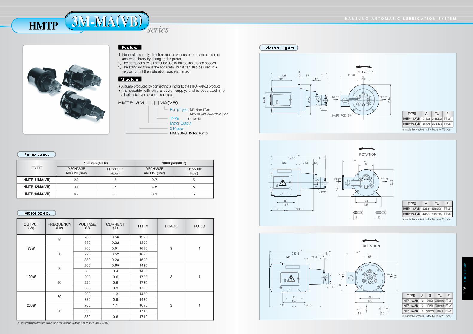
1. Identical assembly structure means various performances can beachieved simply by changing the pump.
2. The compact size is useful for use in limited installation spaces.3. The standard form is the horizontal, but it can also be used in a
vertical form if the installation space is limited.
H A N S U N G A U T O M A T I C L U B R I C A T I O N S Y S T E M
HMTP series3M-MA(VB)3M-MA(VB)
5 / 6
·R
OT
OR
PU
MP
HHMMTT PP -- 33MM-- -- MMAA((VVBB))
Pump Type : MA: Nomal TypeMAVB: Relief Valve Attach Type
TYPE 11, 12, 13
Motor Output3 PhaseHANSUNG Rotor Pump
※ Tailored manufacture is available for various voltage (380V,415V,440V,460V)
OUTPUT(W)
FREQUENCY(Hz)
VOLTAGE(V)
CURRENT(A) R.P.M PHASE POLES
75W
50200 0.56 1390
3 4
380 0.32 1390
60
200 0.51 1660
220 0.52 1690
380 0.28 1690
100W
50200 0.65 1430
3 4
380 0.4 1430
60
200 0.6 1720
220 0.6 1730
380 0.3 1730
200W
50200 1.3 1430
3 4
380 0.9 1430
60
200 1.1 1690
220 1.1 1710
380 0.6 1710
TYPE1500rpm(50Hz) 1800rpm(60Hz)
DISCHARGEAMOUNT(l/min)
PRESSURE(kg/㎠)
DISCHARGEAMOUNT(l/min)
PRESSURE(kg/㎠)
HMTP-11MA(VB) 2.2 5 2.7 5
HMTP-12MA(VB) 3.7 5 4.5 5
HMTP-13MA(VB) 6.7 5 8.1 5
※ Inside the bracket( ) is the figure for VB type
※ Inside the bracket( ) is the figure for VB type
※ Inside the bracket( ) is the figure for VB type
TYPE A TL PHMTP-11MA(VB) 37(52) 241(256) PT1/8”
HMTP-12MA(VB) 42(57) 246(261) PT1/4”
TYPE A TL PHMTP-11MA(VB) 37(52) 234.5(249.5) PT1/8”
HMTP-12MA(VB) 42(57) 239.5(254.5) PT1/4”
TYPE A B TL PHMTP-11MA(VB) 12 37(52) 274.5(289.5) PT1/8”
HMTP-12MA(VB) 12 42(57) 279.5(294.5) PT1/4”
HMTP-13MA(VB) 14 57.5(72.5) 295(310) PT3/8”
˙�…”-10‡�-¿�„fi84p@-‡»`�‚‚#8B5AE 2010.5.10 12:1 PM ˘���`�70

● A cooler unit produced by connecting a fan cooler to theHMTP-3M-□-□MA(VB) pump
●Separated into 7,8,14 liter according to tank capacity
1. A compact cooler unit, and uses a vertical type pump2. Its compact design allows it to be used in limited installation spaces.3. An oil cooler unit with a simple method of installation, and can be usednot only for small machine tools, but also for industrial machines.
H A N S U N G A U T O M A T I C L U B R I C A T I O N S Y S T E M
OIL seriesCOOLERCOOLER
7 / 8
·R
OT
OR
PU
MP
[T 8]
[T 14]
[T 7]
OUTPUT(W)
FREQUENCY(Hz)
VOLTAGE(V)
CURRENT(A) R.P.M PHASE POLES
75W
50200 0.56 1390
3 4
380 0.32 1390
60
200 0.51 1660
220 0.52 1690
380 0.28 1690
100W
50200 0.65 1430
3 4
380 0.4 1430
60
200 0.6 1720
220 0.6 1730
380 0.3 1730
200W
50200 1.3 1430
3 4
380 0.9 1430
60
200 1.1 1690
220 1.1 1710
380 0.6 1710
TYPE1500rpm(50Hz) 1800rpm(60Hz)
DISCHARGEAMOUNT(l /min)
PRESSURE(kg/cm2)
DISCHARGEAMOUNT(l /min)
PRESSURE(kg/cm2)
HMTP-11MA(VB) 2.2 5 2.7 5
HMTP-12MA(VB) 3.7 5 4.5 5
HMTP-13MA(VB) 6.7 5 8.1 5
HHMMTT PP --33MM-- -- MMAA((VVBB )) -- TT
Tank Capacity :7, 8, 14
Pump Type : MA: Nomal TypeMAVB: Relief Valve Attach Type
TYPE : 11, 12, 13Motor Output
HANSUNG Rotor Pump3 Phase
˙�…”-10‡�-¿�„fi84p@-‡»`�‚‚#8B5AE 2010.5.10 12:1 PM ˘���`�72

HHTT PP -- HHAA ((VVBB//VVDD))
Pump Type :HA: Normal TypeHAVB: Relief Valve Attach TypeHAVD: External Relief Valve Attach Type
TYPEHANSUNG Rotor Pump
● An internal gear bulk type pump structure that can operatethe pump with a motor power supply. The connection sectionis identical, but it has a wife range of performances accordingto the shape of the internal gear.
1. It uses a double oil seal to minimize oil leaks.2. Water-soluble cutting fluids can be used.3. It uses a fluoride oil seal, and can be used at high
temperature.4. A relief valve can be attached for easy pressure control.5. VD is an external drain relief valve.
H A N S U N G A U T O M A T I C L U B R I C A T I O N S Y S T E M
HTP seriesHA(VB/VD)HA(VB/VD)
9 / 1
0·
RO
TO
R P
UM
P
TYPE A B N-P TYPE A B N-P
HTP-203HA(VB/VD) 81 5 2-1/2 HTP-210HA(VB/VD) 93 17 2-3/4
HTP-204HA(VB/VD) 83 7 2-1/2 HTP-212HA(VB/VD) 96 20 2-3/4
HTP-206HA(VB/VD) 86 10 2-1/2 HTP-216HA(VB/VD) 103 27 2-3/4
HTP-208HA(VB/VD) 90 14 2-1/2 HTP-220HA(VB/VD) 109 33 2-3/4
TYPE
50Hz 4P(1500rpm) 60Hz 4P(1800rpm)
DISCHARGE(l /min)
MOTOR MAX. PRESSURE (kg/cm2) DISCHARGE(l /min)
MOTOR MAX. PRESSURE (kg/cm2)
400W 750W 1500W 400W 750W 1500W
HTP-203HA(VB/VD) 4.5 30.0 30.0 30.0 5.4 26.0 30.0 30.0
HTP-204HA(VB/VD) 6.3 21.5 30.0 30.0 7.5 16.0 30.0 30.0
HTP-206HA(VB/VD) 9.0 10.5 25.0 25.0 10.8 7.0 23.5 25.0
HTP-208HA(VB/VD) 12.6 7.0 23.0 25.0 15.1 4.0 17.5 25.0
HTP-210HA(VB/VD) 15.3 4.5 15.5 25.0 18.3 2.5 11.5 25.0
HTP-212HA(VB/VD) 18.0 3.5 13.5 20.0 21.6 - 8.5 20.0
HTP-216HA(VB/VD) 24.3 2.0 8.5 20.0 29.1 - 5.5 19.5
HTP-220HA(VB/VD) 29.7 - 5.5 15.5 35.6 - 3.5 14.0
HAVBHA
HAVD
˙�…”-10‡�-¿�„fi84p@-‡»`�‚‚#8B5AE 2010.5.10 12:1 PM ˘���`�74

● A single-unit pump produced by connecting a motor to theHTP-HAVB pump.
● It does not require a separate power source.● It has a wide range of performances according to motoroutput.
1. Various applications are possible according to relief valve shape.2. A coupling connection type, and is easy to maintain.3. The F Type has a built in suction filter, and therefore does not
require additional filter attachments.
H A N S U N G A U T O M A T I C L U B R I C A T I O N S Y S T E M
HMTP series3M-HA(VB/VD)3M-HA(VB/VD)
11 /
12·
RO
TO
R P
UM
P
TYPE
50Hz 4P(1500rpm) 60Hz 4P(1800rpm)
DISCHARGE(l /min)
MOTOR MAX. PRESSURE (kg/cm2) DISCHARGE(l /min)
MOTOR MAX. PRESSURE (kg/cm2)
400W 750W 1500W 400W 750W 1500W
HMTP-203HA(VB/VD) 4.5 30.0 30.0 30.0 5.4 26.0 30.0 30.0
HMTP-204HA(VB/VD) 6.3 21.5 30.0 30.0 7.5 16.0 30.0 30.0
HMTP-206HA(VB/VD) 9.0 10.5 25.0 25.0 10.8 7.0 23.5 25.0
HMTP-208HA(VB/VD) 12.6 7.0 23.0 25.0 15.1 4.0 17.5 25.0
HMTP-210HA(VB/VD) 15.3 4.5 15.5 25.0 18.3 2.5 11.5 25.0
HMTP-212HA(VB/VD) 18.0 3.5 13.5 20.0 21.6 - 8.5 20.0
HMTP-216HA(VB/VD) 24.3 2.0 8.5 20.0 29.1 - 5.5 19.5
HMTP-220HA(VB/VD) 29.7 - 5.5 15.5 35.6 - 3.5 14.0
OUTPUT(W)
FREQUENCY(Hz)
VOLTAGE(V)
CURRENT(A) R.P.M PHASE POLES
400W
50200 2.4 1420
3 4380 1.3 1420
60200 2.2 1700
220 2.2 1720
380 1.2 1720
750W
50200 3.5 1430
3 4380 1.9 1440
60200 3.4 1710
220 3.4 1730
380 1.8 1730
1500W
50200 6.9 1430
3 4380 3.4 1430
60200 6.6 1720
220 6.6 1730
380 3.2 1730
OUTPUT C D E F G L d M N Q R CD H
MOTOR400W 75.5 146 170 245.5 113 F+A 7 114 90 112 144 125 71750W 77.5 169 209 286 139 F+A 10 135 100 123 136 135 801500W 85.5 194 234 319.5 153 F+A 10 156 125 140 172 140 90
TYPE A B N-P TYPE A B N-P
HMTP-203HA(VB/VD) 81 5 2-1/2 HMTP-210HA(VB/VD) 93 17 2-3/4
HMTP-204HA(VB/VD) 83 7 2-1/2 HMTP-212HA(VB/VD) 96 20 2-3/4
HMTP-206HA(VB/VD) 86 10 2-1/2 HMTP-216HA(VB/VD) 103 27 2-3/4
HMTP-208HA(VB/VD) 90 14 2-1/2 HMTP-220HA(VB/VD) 109 33 2-3/4
HHMMTT PP --33MM-- -- HHAA ((VVBB//VVDD)) FF
F : Suction FilterAttach TypePump Type :
VB: Nomal TypeHAVB: Relief Valve Attach TypeHAVD: External Relief Valve Attach Type
TYPEMOTOR OUTPUT3 PhaseHANSUNG Rotor Pump
˙�…”-10‡�-¿�„fi84p@-‡»`�‚‚#8B5AE 2010.5.10 12:1 PM ˘���`�76

13 /
14·
RO
TO
R P
UM
P
Relief valve of the rotor pump is connected directly to thetop of the pump as illustrated below, and the pressure iscontrolled via a suitable spring pressure. To adjust thespring, remove the cap, and rotate the bolt clockwise toincrease the pressure setting and anticlockwise to decreasethe pressure setting. After setting the pressure as needed,fasten the tightening nut and close the cap firmly.
2. Suction pipeThe suction pipe diameter needs to be designed to achieve a peed of 1.5m/sec, and the pumplocation needs to be set to allow the installation of the shortest suction pipe.This is because in order to achieve smooth oil suction, the pipe's total length and curves need tobe minimized.Also, when using highly-viscous oil, you have to use a pipe with a large circumference, and takefriction increase into consideration according to oil viscosity.
3. Suction pressureRotor pump shows high suction pressure at 720mmHg or higher in general if pressured. This figuremeans this pump has high vacuum rates. For the safety matter, piping design must be aimed atmaintaining the suction pressure at lower than-0.5kg/cm2.
4. Using oil filter during suctionIf strange or loud noises come from the filter during pump operation, immediately stop operationand check the pump and filter quantities.The oil quantity that passes through the filter requires more than twice the amount of discharge.
5. PipingThe most suitable pipe diameter is one that can maintain a speed of at least 3m/sec.The discharge pipe, as opposed to the suction pie, needs to have a small pipe diameter. Pressureloss caused by pipe friction is added to the downward pressure, and is not applied to the pump.Hence, you have to choose the right pipe diameter within the oil speed range by taking the lossinto consideration, and if the quantity of oil passing through the pipes and the valves is small, oilspeed will increase and cause chaotic oil flow.
6. Relation with Pump speedFor high-viscosity, small quantities of oil are discharged at high speeds, and veice versa.Hence, for high-viscosity oil, operation should be slow, taking factors such as noise intoconsideration.
7. Speed for oil with high viscosityIn the case of oil with high viscosity, the amount of oil flow decreases at high speed and vice versa. Oilwith high viscosity is desirable for low speed drive in order for low noise.
8. Installation of PumpIt must be installed in the place with good ventilation and beyond the reach of splash of theliquid and easy access to check and repair. Pump must be installed a little bit higher than thesurface of the water.
1. Direction of rotationIt should rotate as the arrow direction. If backlashhappens, oil seal could be destroyed. Rotor pumpdischarges like the drawing in normal condition. It isdesigned for pressure to send oil to oil seal partthrough the shaft and then return it into suction partthrough the drain hole. However, if the pumpbacklash, suction and delivery go into reverse sothat oil stays in oil seal through drain hole resulting indamage in the oil seal and adverse oil flow.
9. Installation of PumpThe adequate amount of oil inside the tank is 3~4 timesthe pump's per minute oil quantity.If a small tank is produced to reduce space usage, the oilsupply may become insufficient, and cause unstablepump suction. Even with fast oil recovery to the tank, theunstable oil condition will raise oil temperature and causeoil contamination.The oil temperature at the suction section needs to bemaintained at below 55℃
< Relief Valve Operation Order >
H A N S U N G A U T O M A T I C L U B R I C A T I O N S Y S T E M
Product Installation Methods
˙�…”-10‡�-¿�„fi84p@-‡»`�‚‚#8B5AE 2010.5.10 12:1 PM ˘���`�78

Cause & Remedy of Trouble
It is used as a safety valve to send the pump dischargepressure safely.This valve is connected directly to the top of the pump, anddoes not operate under normal conditions. When the pump'spressure exceeds the preset pressure, the valve opens, andsome oil from the discharge section flows back into the suctionsection.This valve is a safety valve that can motor overload as well aspump overloads. If this valve is always moving or is left open forprolonged periods of time, it can cause bubbles, noise, andtemperature increases. Therefore, in such cases, a differentvalve needs to be used.
It has the same structure as the above method of use, but thedrained oil is sent inside the tank, and therefore it can preventoverload inside the pump compared to the VBtype.
SSttaattuuss CCaauussee CCoouunntteerrmmeeaassuurreess
Small dischargequantity
Insufficient tank oil Replenish oil
Faulty suction Clean suction filter and prevent air adulteration
Faulty pump rotation Check pump rotation direction
High oil viscosity Maintain optimum viscosity
Faulty valve control Readjust valve
Reduced pressure
Same as abovementioned item Same as abovementioned item
Large amounts of internal leakage Adjust or exchange each packing and seal
Large amounts of external leakage Examine pump, valve and each pipe
Oil leakageFaulty pipe condition Improve piping method and examine oil leak area
Packing seal damage Exchange
PUMP noiseCavitation
AIR adulteration, FILTER clogging, insufficient OIL inside TANKCheck OIL viscosity and take measures
Pump component damage Contact head office and other offices
Irregular VALVEoperation
Adulteration of foreign substances Prevent adulteration of foreign substances
Valve damage Exchange damaged valve
Oil overheating
High oil Viscosity Maintain optimum viscosity
Insufficient oil inside tank Replenish oil
High pressure settings Examine and make adjustments
High discharge settings Examine and make adjustments
Irregular pipe path Repair pipe path
Irregular operation ofPump
Air adulteration Prevent air adulteration
Excessive wear or damage Replace parts and make readjustments
15·
RO
TO
R P
UM
P
˙�…”-10‡�-¿�„fi84p@-‡»`�‚‚#8B5AE 2010.5.10 12:1 PM ˘���`�80