r&s pulse sequencer: pdw import interface specification · r&s®pulse sequencer pdw import...
TRANSCRIPT
R&S®Pulse SequencerPDW Import InterfaceInterface Specification
Inter
face S
pecif
icatio
n
Versi
on 02
1178390502(;ÜW52)

This manual describes software version V1.6 and later of the R&S®Pulse Sequencer.
© 2018 Rohde & Schwarz GmbH & Co. KGMühldorfstr. 15, 81671 München, GermanyPhone: +49 89 41 29 - 0Fax: +49 89 41 29 12 164Email: [email protected]: www.rohde-schwarz.comSubject to change – Data without tolerance limits is not binding.R&S® is a registered trademark of Rohde & Schwarz GmbH & Co. KG.Trade names are trademarks of the owners.
1178.3905.02 | Version 02 | R&SPulse Sequencer
The following abbreviations are used throughout this manual: R&S®Pulse Sequencer is abbreviated as R&S Pulse Sequencer.
ContentsR&S®Pulse Sequencer
3Interface Specification 1178.3905.02 ─ 02
Contents1 Overview................................................................................................. 5
2 PDW Import Mechanism........................................................................6
3 Template Syntax.....................................................................................83.1 Header Directives..........................................................................................................9
3.1.1 COMMENT......................................................................................................................9
3.1.2 START_LINE.................................................................................................................10
3.1.3 END_LINE.....................................................................................................................10
3.1.4 COLUMN_SEPARATOR............................................................................................... 11
3.1.5 DECIMAL_CHAR.......................................................................................................... 11
3.2 Column Definitions..................................................................................................... 11
3.2.1 General Type Tags........................................................................................................ 11
3.2.2 TOA Tag........................................................................................................................ 13
3.2.3 MOP Type Identifiers.....................................................................................................14
3.2.4 AM/FM Specific Parameters......................................................................................... 15
3.2.5 Chirp Specific Parameters............................................................................................ 15
3.2.6 ASK, FSK, PSK Specific Parameters............................................................................16
3.2.7 Barker Specific Parameters.......................................................................................... 18
3.2.8 Custom Phase Specific Parameters............................................................................. 18
4 PDW File Syntax...................................................................................19
5 Regular Expression Matching.............................................................20
ContentsR&S®Pulse Sequencer
4Interface Specification 1178.3905.02 ─ 02

OverviewR&S®Pulse Sequencer
5Interface Specification 1178.3905.02 ─ 02
1 OverviewStarting at R&S Pulse Sequencer software version V1.4 the waveform object canimport custom text-based PDW lists. This imported data is stored inside the repositoryand during scenario calculation a waveform or extended sequencer data is generatedfrom this PDW data.
Scope
This document serves as an interface specification for the PDW list file as well as therequired template for parsing the PDW list file.
We assume that you are familiar with the R&S Pulse Sequencer principles, nomencla-ture and user interface.
This document does not describe the operating of the software and does not substitutethe R&S Pulse Sequencer user manual. This document is intended to guide you writingexport filters to convert emitter database records into a format that R&S PulseSequencer can read.

PDW Import MechanismR&S®Pulse Sequencer
6Interface Specification 1178.3905.02 ─ 02
2 PDW Import MechanismR&S Pulse Sequencer uses a template-based import mechanism for the PDW import.Import templates are human readable text files that describe how information is extrac-ted from the PDW list file. The PDW list file is also a human readable text file using onesingle row per PDW. The columns contain the various parameters related to the PDW.
The diagram on Figure 2-1 shows the principal concept.
Figure 2-1: Import mechanism principle
The "PDW Data Import" wizard is a dialog that loads both files and shows their content.This dialog is also used to control the import process and accept the imported data.
The import process starts by parsing the text-based template file. Once parsing thetemplate is complete, R&S Pulse Sequencer loads and analyzes the PDW list file. Allimported data is temporarily stored in memory until you choose to store the data per-manently in the repository.
Storing the data lets R&S Pulse Sequencer copy the extracted PDW data to a wave-form object within the R&S Pulse Sequencer repository. The internal storage format isa proprietary binary stream. If future extensions to the data stream are required,R&S Pulse Sequencer automatically converts existing streams to the newer format.
After the import process has completed the original template and PDW files are no lon-ger required.
The waveform container with the PDW information can be used as part of a sequenceor as a background emitter, for example. Thus, using this signal is identical to using a
PDW Import MechanismR&S®Pulse Sequencer
7Interface Specification 1178.3905.02 ─ 02
captured RF signal, digital standard signals originating from R&S® WinIQSIM2TM, orbackground emitter noise.
Template SyntaxR&S®Pulse Sequencer
8Interface Specification 1178.3905.02 ─ 02
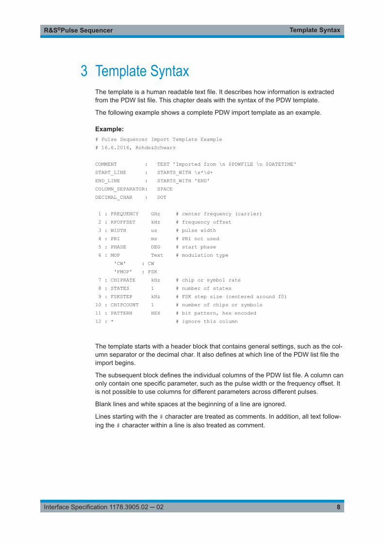
3 Template SyntaxThe template is a human readable text file. It describes how information is extractedfrom the PDW list file. This chapter deals with the syntax of the PDW template.
The following example shows a complete PDW import template as an example.
Example: # Pulse Sequencer Import Template Example# 16.6.2016, Rohde&Schwarz
COMMENT : TEXT 'Imported from \n $PDWFILE \n $DATETIME'START_LINE : STARTS_WITH \s*\d+END_LINE : STARTS_WITH 'END'COLUMN_SEPARATOR: SPACEDECIMAL_CHAR : DOT
1 : FREQUENCY GHz # center frequency (carrier) 2 : RFOFFSET kHz # frequency offset 3 : WIDTH us # pulse width 4 : PRI ms # PRI not used 5 : PHASE DEG # start phase 6 : MOP Text # modulation type 'CW' : CW 'FMOP' : FSK 7 : CHIPRATE kHz # chip or symbol rate 8 : STATES 1 # number of states 9 : FSKSTEP kHz # FSK step size (centered around f0)10 : CHIPCOUNT 1 # number of chips or symbols11 : PATTERN HEX # bit pattern, hex encoded12 : * # ignore this column
The template starts with a header block that contains general settings, such as the col-umn separator or the decimal char. It also defines at which line of the PDW list file theimport begins.
The subsequent block defines the individual columns of the PDW list file. A column canonly contain one specific parameter, such as the pulse width or the frequency offset. Itis not possible to use columns for different parameters across different pulses.
Blank lines and white spaces at the beginning of a line are ignored.
Lines starting with the # character are treated as comments. In addition, all text follow-ing the # character within a line is also treated as comment.

Template SyntaxR&S®Pulse Sequencer
9Interface Specification 1178.3905.02 ─ 02
3.1 Header Directives
The header section is always the first part of a PDW import template. It sets generalparameters that concern the import.
The general syntax of all header directives is identical. An initial keyword is separatedby a colon from all following parameters.
<Keyword> : <Parameter> [<Data>]All keywords and their parameters are described in this chapter. The keywords andparameters are not case-sensitive.
3.1.1 COMMENT
The COMMENT directive defines how a comment can be extracted from the PDW listfile. This comment is automatically copied to the comment of the waveform object inthe R&S Pulse Sequencer repository.
The following parameters are supported:● TEXT '<String>'● LINE <Line Number>The TEXT parameter directly defines a text that is copied to the comment field. In thiscase, no information from the PDW list file is extracted.
LINE specified a fixed line in the PDW file. The content of this line is used as the com-ment. The line number is one-based.
Example: COMMENT LINE 3COMMENT TEXT 'Imported on $DATETIME'
This example reads the text from line 3 of the PDW file into the comment field of thewaveform object.
The text retrieved from the PDW list file or directly set through the TEXT option cancontain variables that are evaluated during the PDW import process. The variablenames are not case-sensitive.
$PDWFILE PDW list filename (without path)
$PDWPATHFILE PDW list path and filename
$DATETIME Current date and time in short local format
$ISODATETIME Current date and time in ISO format
(YYYY-MM-DDTHH:mm:ssTZD)
Header Directives
Template SyntaxR&S®Pulse Sequencer
10Interface Specification 1178.3905.02 ─ 02
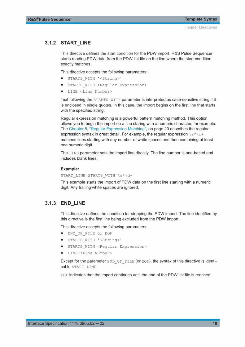
3.1.2 START_LINE
This directive defines the start condition for the PDW import. R&S Pulse Sequencerstarts reading PDW data from the PDW list file on the line where the start conditionexactly matches.
This directive accepts the following parameters:● STARTS_WITH '<String>'● STARTS_WITH <Regular Expression>● LINE <Line Number>Text following the STARTS_WITH parameter is interpreted as case-sensitive string if itis enclosed in single quotes. In this case, the import begins on the first line that startswith the specified string.
Regular expression matching is a powerful pattern matching method. This optionallows you to begin the import on a line staring with a numeric character, for example.The Chapter 5, "Regular Expression Matching", on page 20 describes the regularexpression syntax in great detail. For example, the regular expression \s*\d+matches lines starting with any number of white spaces and then containing at leastone numeric digit.
The LINE parameter sets the import line directly. The line number is one-based andincludes blank lines.
Example: START_LINE STARTS_WITH \s*\d+This example starts the import of PDW data on the first line starting with a numericdigit. Any trailing white spaces are ignored.
3.1.3 END_LINE
This directive defines the condition for stopping the PDW import. The line identified bythis directive is the first line being excluded from the PDW import.
This directive accepts the following parameters:● END_OF_FILE or EOF● STARTS_WITH '<String>'● STARTS_WITH <Regular Expression>● LINE <Line Number>Except for the parameter END_OF_FILE (or EOF), the syntax of this directive is identi-cal to START_LINE.
EOF indicates that the import continues until the end of the PDW list file is reached.
Header Directives

Template SyntaxR&S®Pulse Sequencer
11Interface Specification 1178.3905.02 ─ 02
3.1.4 COLUMN_SEPARATOR
The column separator defines the character that is used as the delimiter between indi-vidual columns of a PDW file. Multiple delimiting characters in a sequence are treatedas one delimiter.
This directive accepts the following parameters:● SPACE● SEMICOLON● COMMAThe space character (0x20) is the default delimiter if this directive is omitted.
3.1.5 DECIMAL_CHAR
The decimal character applies to all number conversions.
This directive accepts the following parameters:● DOT● COMMAThe DOT is the default decimal character if this option is omitted.
3.2 Column Definitions
The column definitions specify which information is provided in the columns of thePDW list file. A column can only be used for one specific parameter.
The general syntax for the column definition in the PDW file is as follows:
<row> : <type tag> <unit>The <row> is a one-based number. A PDW template can only contain one singledescription for each row number.
The <type tag> denominates the information provided in that specific row. A detailedlist of all available type tags is provided in Chapter 3.2.1, "General Type Tags",on page 11.
The <unit> can be used to translate a numeric value, e.g. from us to seconds. Theunit applies to all values in a column.
3.2.1 General Type Tags
Table 3-1 lists all general type tags. These type tags are valid for all pulses and do notdepend on other parameters, such as MOP.
Column Definitions
Template SyntaxR&S®Pulse Sequencer
12Interface Specification 1178.3905.02 ─ 02
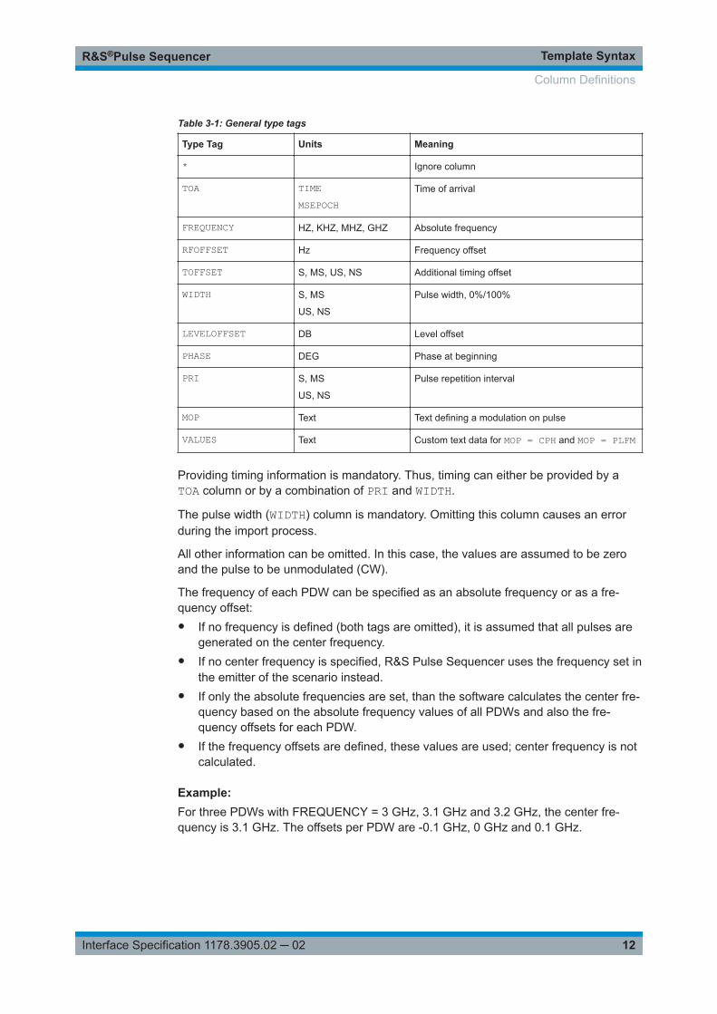
Table 3-1: General type tags
Type Tag Units Meaning
* Ignore column
TOA TIMEMSEPOCH
Time of arrival
FREQUENCY HZ, KHZ, MHZ, GHZ Absolute frequency
RFOFFSET Hz Frequency offset
TOFFSET S, MS, US, NS Additional timing offset
WIDTH S, MS
US, NS
Pulse width, 0%/100%
LEVELOFFSET DB Level offset
PHASE DEG Phase at beginning
PRI S, MS
US, NS
Pulse repetition interval
MOP Text Text defining a modulation on pulse
VALUES Text Custom text data for MOP = CPH and MOP = PLFM
Providing timing information is mandatory. Thus, timing can either be provided by aTOA column or by a combination of PRI and WIDTH.
The pulse width (WIDTH) column is mandatory. Omitting this column causes an errorduring the import process.
All other information can be omitted. In this case, the values are assumed to be zeroand the pulse to be unmodulated (CW).
The frequency of each PDW can be specified as an absolute frequency or as a fre-quency offset:● If no frequency is defined (both tags are omitted), it is assumed that all pulses are
generated on the center frequency.● If no center frequency is specified, R&S Pulse Sequencer uses the frequency set in
the emitter of the scenario instead.● If only the absolute frequencies are set, than the software calculates the center fre-
quency based on the absolute frequency values of all PDWs and also the fre-quency offsets for each PDW.
● If the frequency offsets are defined, these values are used; center frequency is notcalculated.
Example: For three PDWs with FREQUENCY = 3 GHz, 3.1 GHz and 3.2 GHz, the center fre-quency is 3.1 GHz. The offsets per PDW are -0.1 GHz, 0 GHz and 0.1 GHz.
Column Definitions

Template SyntaxR&S®Pulse Sequencer
13Interface Specification 1178.3905.02 ─ 02
3.2.2 TOA Tag
The TOA data can be provided in two different formats, see:● "TIME format" on page 13● "SEPOCH and MSEPOCH format" on page 14
The absolute time information of the PDW data is removed during import. Instead thefirst pulse is always set to T = 0 and all following pulses use the time difference relatedto this pulse.
As an alternative to providing TOA directly it is also possible to use a combination ofWIDTH and PRI. In this case, the time starts at T = 0 and the start time of the currentpulse is derived from the start time and PRI of the previous pulse.
TOA has priority over PRI. Hence, if both values are provided, then PRI is ignored.
TIME format
Using the TIME format requires an additional line in the template immediately followingthe column definition for the TOA column. This line contains the detailed format specifi-cation of the date/time format.
The following example demonstrates how to define the TOA in TIME format.
Example: 1 : TOA TIME # TOA provided in TIME format 'hh:mm:ss.zzzzzzzzz'2 : RFOFFSET MHz # Frequency offset3 : WIDTH us # Pulse width
The following characters are supported in the date/time string. The characters arecase-sensitive.
Character Meaning
d day
M month
y year
h hour
m minute
s second
z milliseconds
The length of the milliseconds field is usually 3 digits long and permit values from 000to 999. R&S Pulse Sequencer uses an extended field where microseconds and nano-seconds can be added without using a decimal point or any extra character.
In the above example, the character z is used nine times which means that the lastdigit has nanoseconds resolution.
Column Definitions

Template SyntaxR&S®Pulse Sequencer
14Interface Specification 1178.3905.02 ─ 02
SEPOCH and MSEPOCH format
(seconds/milliseconds since start of epoch)
Using these time formats does not require an extra line in the template. Both formatsexpect the timestamp as floating point number in seconds/milliseconds since1970-01-01T00:00:00.0000 UTC.
3.2.3 MOP Type Identifiers
The MOP entry always requires the unit to be set to TEXT. This unit type instructsR&S Pulse Sequencer to convert a custom text field into an internal MOP type. UsingTEXT requires a translation block in the template file immediately following the linedefining the TEXT columns. This translation block uses the general format:
'<text>' : <id>Table 3-2 lists the supported MOP types (<id>).
Table 3-2: Supported MOP tags
MOP Tag Meaning
CW Unmodulated
AMFM
Amplitude modulation
Frequency modulation
ASKFSKPSK
Amplitude shift keying
Frequency shift keying
Phase shift keying
LFMNLFMTFMPLFM
Linear frequency modulation (chirp)
Non-linear chirp
Triangular chirp
Piecewise linear chirp
BKR3BKR4ABKR4BBKR5BKR7BKR11BKR15
Barker pulse
CPH Custom phase
The following is an example of a MOP entry in the PDW template file.
Column Definitions

Template SyntaxR&S®Pulse Sequencer
15Interface Specification 1178.3905.02 ─ 02
Example: 5 : MOP TEXT 'UNM' : CW 'LIN' : LFM 'TRI' : TFM 'SLAW' : NLFM
This example defines column 5 of the PDW file to contain text that specifies the MOPtype. The text 'UNM' translates into the MOP type CW which means an unmodulatedpulse is generated. 'LIN' creates a linear frequency modulated chirp. 'TRI' createsa triangular chirp. 'SLAW' is used to create a non-linear chirp with quadratic and cubicterm.
Each MOP type requires a specific set of parameters, see:● Chapter 3.2.4, "AM/FM Specific Parameters", on page 15● Chapter 3.2.5, "Chirp Specific Parameters", on page 15● Chapter 3.2.6, "ASK, FSK, PSK Specific Parameters", on page 16● Chapter 3.2.7, "Barker Specific Parameters", on page 18● Chapter 3.2.8, "Custom Phase Specific Parameters", on page 18
3.2.4 AM/FM Specific Parameters
Table 3-3 describes parameters that are related to the AM or FM modulation.
Table 3-3: AM/FM specific parameters
Type Tag Units Meaning
MODFREQ HZ, KHZ
MHZ, GHZ
AM, FM modulation frequency
AMDEPTH PERCENT AM modulation depth
FMDEVIATION HZ, KHZ,
MHZ, GHZ
FM deviation
The above parameters are mandatory if AM or FM is used. All pulses not using thisMOP type can set the column value in the PDW list file to 'N/A'.
3.2.5 Chirp Specific Parameters
Table 3-4 describes parameters that only concern chirped pulse modulation schemes(LFM, NLFM, TFM, see Table 3-2).
Column Definitions

Template SyntaxR&S®Pulse Sequencer
16Interface Specification 1178.3905.02 ─ 02
Table 3-4: Chirp-specific parameters
Type Tag Units Meaning
CHRATE HZ/S, KHZ/S
HZ/MS, HZ/US,
KHZ/US
LFM, TFM chirp rate
NLFM_LIN 1 NLFM linear factor
NLFM_Q 1 NLFM quadratic factor
NLFM_C 1 NLFM cubic factor
VALUES - Value triples separated by "|"
The parameter CHRATE is mandatory for all linear chirps. A positive value indicates achirp sweeping from a lower to a higher frequency.
The parameter NLFM_x is mandatory for all non-linear NLFM chirps. The frequencywithin the chirp is calculated by the following equation.
f(x) = NLFMLIN*x + NLFMQ*x2 + NLFMC*x3, where
x = -1 to +1
The parameter VALUES is mandatory for the piecewise liner chirp PLFM.
It is a sequence of triples separated by "|", where each triple describes a part of thepiecewise linear chirp. A triple is a comma-separated sequence of values, describingthe duration, the rate and the frequency offset in each part of the liner chirp. The syn-tax is as follows:
<duration#1>,<rate#1>,<offset#1>|...|<duration#N>,<rate#N>,<offset#N>, where:● N is the number of parts of the piecewise chirp● Triple parameters are defined in Table 3-5.
Table 3-5: PLFM-specific parameters
Triple parame-ters
Units Value range Meaning
<duration> % 0 to 100 Duration of the chirp part
<rate, us> Hz - 1 GHz to 1 GHz
<offset> Hz - 1 GHz to 1 GHz Offset during the chirp part
Example: 10,4e6,10e6|20,1e6,20e6|30,1.5e6,30e6
3.2.6 ASK, FSK, PSK Specific Parameters
Table 3-6 describes parameters that only affect the ASK, FSK and PSK modulationschemes.
Column Definitions

Template SyntaxR&S®Pulse Sequencer
17Interface Specification 1178.3905.02 ─ 02
Table 3-6: ASK, FSK, PSK-specific parameters
Type Tag Units Meaning
CHIPRATE HZ, KHZ
MHZ, GHZ
Chip or symbol rate
STATES 1 Number of states, e.g. levels, frequencies, phases
CHIPCOUNT 1 Number of chips or symbols
PATTERN HEX
BINARY
Data bits
ASKSTEP DB ASK level steps
FSKSTEP HZ, KHZ,
MHZ, GHZ
FSK frequency steps
PSKSTEP DEG PSK phase steps
The parameters CHIPRATE, STATES, CHIPCOUNT and PATTERN are common to allMOP types.
CHIPRATE in Hz specifies the rate at which symbols occur within the pulse. Thisparameter is mandatory.
STATES describe how many different amplitude, frequency or phase values an individ-ual symbol can have. If this parameter is omitted, a value of two is assumed. The maxi-mum permissible values for this parameter are 16.
CHIPCOUNT is the number of symbols that occur within the pulse. If this number isomitted, a value of two is assumed. The maximum chip count is 16.
The PATTERN parameter contains the data used for the MOP. In HEX format, an 8bytes hexadecimal value is used to provide the data for up to 16 symbols with 16states each. Each character of the hexadecimal value describes one single symbol. Ifthis value is omitted, an alternating sequence of zeros and ones is assumed. The max-imum permissible value for each digit depends on the number of states defined for theMOP. The pattern data can also be provided in binary format in which case the stringmust contain a series of ASCII ones and zeros.
ASKSTEP defines a step size for the ASK in dB. The resulting level attenuationdepends on the symbol value according to the following equation.
LeveldB = -SymVal * ASKSTEPdB
Where SymVal = 0 to (STATES - 1).
FSKSTEP defines the frequency step size for the FSK modulation. The individual stepsof this modulation are centered symmetrically around the center frequency. For exam-ple, a binary FSK uses -FSKSTEP/2 and +FSKSTEP/2 as the frequency for symbol zeroand symbol one.
PSKSTEP provides the step size for the PSK modulation. The individual phase stepsare centered on 0 degrees phase shift. Thus, a phase step of 180 degrees generates a
Column Definitions

Template SyntaxR&S®Pulse Sequencer
18Interface Specification 1178.3905.02 ─ 02
value of -90 degrees and +90 degrees. If this parameter is omitted, a value of 180degrees is assumed.
3.2.7 Barker Specific Parameters
This modulation scheme does not use any specific parameters.
3.2.8 Custom Phase Specific Parameters
Table 3-7 describes parameters that only affect the CPH modulation scheme.
Table 3-7: CPH-specific parameters
Type Tag Units Meaning
VALUES DEG Comma-separated phase values with value range: -180 deg to180 deg
The intervals the phases are used are distributed equidistant where the interval dura-tion is equal to the pulse width divided by the number phase values.
Example: 30,40,135,120
Column Definitions

PDW File SyntaxR&S®Pulse Sequencer
19Interface Specification 1178.3905.02 ─ 02
4 PDW File SyntaxThe general format of a PDW file is human readable ASCII text. The content of the fileis interpreted by a text-based template file.
The following example shows a PDW file containing seven pulses.
Example: # Pulse Sequencer PDW File# FSK example
RF Offset PW PRI Phase MOP Rate States Step Syms Data GHz kHz µs ms Deg kHz kHz Hex Value-------------------------------------------------------------------------------------------------- 3.0 0.000 50.0 2.0 0.0 CW N/A N/A N/A N/A N/A 3.0 0.000 160.0 2.0 0.0 FMOP 100.0 2 2000.0 16 0x1010101010101010 3.0 0.000 160.0 2.0 0.0 FMOP 100.0 4 1000.0 16 0x1230001111001230 3.0 0.000 80.0 2.0 0.0 FMOP 100.0 8 250.0 8 0x12345670 3.0 0.000 40.0 2.0 0.0 FMOP 100.0 16 500.0 4 0xFCA5 3.0 0.000 160.0 2.0 0.0 FMOP 100.0 16 100.0 16 0x0123456789ABCDEF 3.0 0.000 50.0 2.0 0.0 CW N/A N/A N/A N/A N/A END
Pulses .......................... 5 FSK modulated, 2 CWLast TOA ........................ 12 msCenter frequency ................ 3 GHzBandwidth ....................... 0 for the frequency hopsLevel range ..................... 0 dB
All PDW parameters are provided in individual columns. The delimiting character aswell as the decimal character are defined in the template.
Columns must provide an entry in each line. If a value is not needed for a pulse, thetext 'N/A' must be used. This text entirely avoids parsing the value at this position.This is useful if a parameter is not needed for a specific pulse entry. If a value is provi-ded the import wizard also performs a range check. Thus, simply setting an unusedparameter to zero is not always an option.
Pulses must not overlap in time. If this condition is detected the import stops and anerror is generated.

Regular Expression MatchingR&S®Pulse Sequencer
20Interface Specification 1178.3905.02 ─ 02
5 Regular Expression MatchingThis section describes the most important aspects of the regular expression patternmatching. For more detailed description, refer to the QRegExp class documentation ofQT 5 (http://doc.qt.io/qt-5/).
Single characters
. The dot matches any character
c A character represents itself unless it has a special regular expression meaning
\c A character that follows a backslash matches the character itself
\n Matches the ASCII line feed
\r Matches the ASCII carriage return
\t Matches the ASCII horizontal tab
\d Matches a decimal digit (e.g. numbers, -, +)
\D Matches a non-digit
\s Matches a white space character
\S Matches a non-whitespace character
\w Matches a word character
\W Matches a non-word character
Sets of characters
A set of characters can be defined by enclosing the individual characters in squarebrackets. Writing [abcx] therefore matches the characters a, b, c and x.
A caret (^) negates the character set if it occurs as the first character in the squarebrackets. A dash (-) indicates a range of characters.
Example:
[a-z] Matches the characters a,b,c to z
[^abc] Matches anything but a,b,c
[0-9] Matches the numbers 0 to 9, this is equal to \d
Quantifiers
The characters or character sets explained above are by default treated as single char-acter. Quantifiers following a character define if characters occur more than once.
? Matches zero or one occurrence, e.g. 'xyz?' matches xy and xyz
+ Matches one or more occurrences, e.g. [0-9]+ matches any length positive integer num-ber
Regular Expression MatchingR&S®Pulse Sequencer
21Interface Specification 1178.3905.02 ─ 02
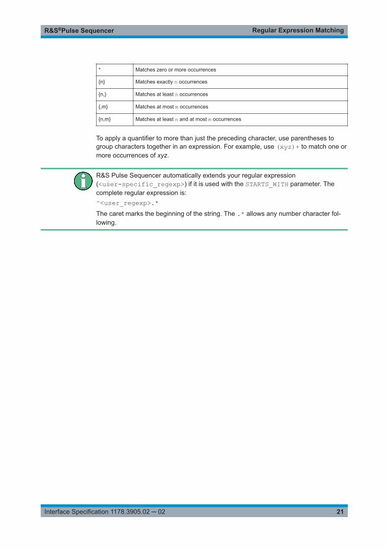
* Matches zero or more occurrences
{n} Matches exactly n occurrences
{n,} Matches at least n occurrences
{,m} Matches at most m occurrences
{n,m} Matches at least n and at most m occurrences
To apply a quantifier to more than just the preceding character, use parentheses togroup characters together in an expression. For example, use (xyz)+ to match one ormore occurrences of xyz.
R&S Pulse Sequencer automatically extends your regular expression(<user-specific_regexp>) if it is used with the STARTS_WITH parameter. Thecomplete regular expression is:^<user_regexp>.*The caret marks the beginning of the string. The .* allows any number character fol-lowing.