sanitary sewer standards urbana & champaign …
TRANSCRIPT
SANITARY SEWER STANDARDS
URBANA & CHAMPAIGN SANITARY DISTRICT
AND
AFFILIATED COMMUNITIES
CHAMPAIGN
URBANA
SAVOY
Prepared by:
Intergovernmental Joint Sanitary Sewer Technical Committee
Effective November 2nd 2020
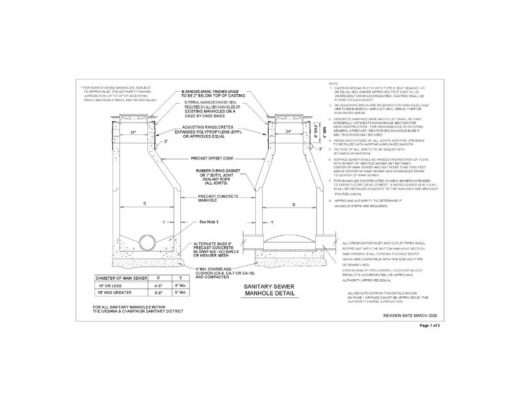
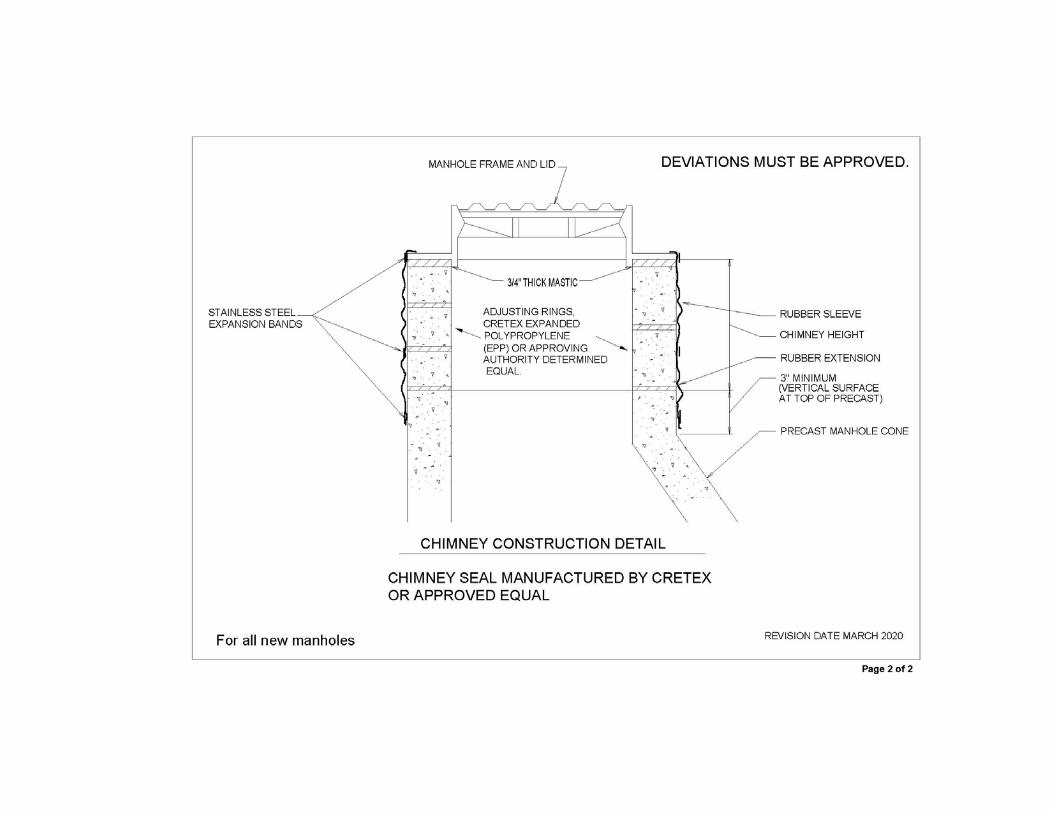
SANITARY SEWER STANDARDS 100.00 PIPE MATERIALS Pipe materials used for sanitary sewers shall conform to the following materials which are expressly manufactured for transmitting sanitary sewage and shall comply with requirements of the Illinois Environmental Protection Agency: SDR 26(minimum thickness) Solid Wall PVC pipe per ASTM D-3034 (4-inch through15-inch), SDR 26 (minimum thickness) Solid Wall PVC pipe per ASTM DF679 (18-inch through 60-inch), PVC profile pipe (18-inch diameter and larger) per ASTM F949 or ASTM 1803, centrifugally-cast fiberglass-reinforced polymer mortar pipe per ASTM D3262 (18-inch through 60-inch), ductile iron per AWWA C150, and others approved by the Executive Director of the UCSD with the concurrence of the approving authority. Ductile iron pipe shall have an interior coating to protect against corrosion consisting of Protecto 401 ceramic epoxy or polyethylene lining. Interior coating shall have a nominal thickness of 40 mils. Polyethylene lining shall be in accordance with ASTM D1248 and be heat fused. For trenchless construction, materials and methods will be approved on a case-by-case basis by the approving authority. 110.0 MANHOLES Manholes shall comply with minimum standards in the “STANDARD SPECIFICATIONS FOR WATER AND SEWER MAIN CONSTRUCTION IN ILLINOIS latest edition” and shall be a minimum of four- feet in diameter. An external manhole chimney seal shall be required on all new manholes.
111.0 DROP MANHOLE CONNECTIONS
All new drop manholes shall be a minimum of five-foot diameter. Drop manhole installations, for 8-inch collector sewers and service lines connecting to five-foot or greater diameter manholes, shall be installed as internal to the manhole structure. Drop connections to existing manholes less than five-foot diameter shall be external and shall comply with the appropriate provisions and details in the “STANDARD SPECIFICATIONS FOR WATER AND SEWER MAIN CONSTRUCTION IN ILLINOIS, latest edition”. A minimum of a five-foot diameter manhole shall be required for internal drop assemblies. Internal drop assembly shall be a RELINER® drop bowl system or engineer approved equal. The drop bowl system shall include a drop bowl assembly, pipe clamps, pipe, and pipe fittings. Pipe and pipe fittings shall be SDR 26 PVC pipe in accordance with Section 100. Drop bowl system shall be installed in accordance with manufacturer’s recommendations The location and details of proposed internal drop assemblies must be approved by the approving authority prior to initiation of construction.

112.0 TERMINAL MANHOLE CONNECTIONS Manholes at the upstream end of dead-end lines shall be constructed so that influent service connections are only attached to the manhole at the upstream side. Further, there shall be a minimum of 4 inches of elevation difference from the invert of the service connection to the invert of the outlet pipe. There shall also be a concrete channel constructed from the invert of the service connection to the channel of the bench outlet pipe. Details of the connection shall be approved by the appropriate agency prior to initiation of construction. 113.0 CONNECTIONS TO EXISTING MANHOLES New connections made to any existing manhole shall be angled in the direction of flow, and shall be accomplished by core drilling through the wall of the manhole and installing an appropriately sized connector boot, such as KOR n SEAL® by Trelleborg, Z-LOK by A-LOK Products, Incorporated, or approving authority approved equal. 114.0 MANHOLE REQUIREMENTS Manholes constructed shall conform to the “Sanitary Sewer Manhole Detail” attached to these Sanitary Sewer Standards.
120.0 SERVICE LATERALS
The minimum inside diameter of new service laterals or clean-outs shall be 4-inches. No reduction in new service lateral pipe diameter is permitted from the structure to the public sanitary sewer. Existing 4-inch service laterals may be lined one time, resulting in a final internal diameter less than 4-inches.
Pipe materials used for sanitary sewer laterals shall conform to the following materials which are expressly manufactured for transmitting sanitary sewage:
Solid wall PVC with a minimum wall thickness equivalent to SDR 26 or Schedule 40 which meets ASTM D-3034, D-224, or D-2665; and ductile iron per AWWA C150. Ductile iron pipe shall have an interior coating to protect against corrosion consisting of Protecto 401 ceramic epoxy or polyethylene lining. Interior coating shall have a nominal thickness of 40 mils. Polyethylene lining shall be in accordance with ASTM D1248 and be heat fused. PVC Pipe joints for SDR-26 shall be push-on-type with a bell-end groove to receive a synthetic rubber gasket. Solvent welded joints are not allowed for SDR-26. The joint shall be made in accordance with ASTM D-3212. Schedule 40 PVC joints can be solvent-cemented. The cement shall meet the requirements of ASTM D-2564.
If laterals are constructed of 6-inch pipe, they shall have a minimum slope of 1/8-inch per foot (1%). 4-inch pipe shall have a minimum slope of ¼-inch per foot (2%). All laterals shall be installed at a depth to serve the building it is designed to serve, but shall have a minimum cover of 42-inches unless otherwise approved on a case-by-case basis by the approving authority. The end of the lateral shall be at no deeper than seven-feet below the existing grade. The end of the lateral shall be staked with a 2 x 4 wood leader which extends to one-foot above the ground and the coordinates of the end of the lateral shall be measured using Global Positioning System survey grade equipment using the Illinois State Plane Coordinate System and the coordinates recorded on the as-built drawings for the sanitary sewer Manholes are required on any service lateral that that exceeds 6-inches in inside diameter. Manholes shall comply with section 110.00 VAC-A-TEE® by LMK Technologies shall be acceptable for clean-outs on existing sewer lateral lines. Each service connection shall be installed to the property line and shall be installed no closer than five-feet to any property corner. A sewer lateral clean-out located on private property shall be required on all sewer lateral pipe repairs that involve replacing over fifty-percent of the lateral pipe. If the lateral already has an existing clean-out no additional clean-outs are required. The clean-out shall NOT be located in either public right-of-way or utility easement unless authorized by the approving authority
124.0 PIPEBURSTING SEWER LATERAL REPLACEMENT
1. CONTRACTOR’S QUALIFICATIONS The Contractor shall be trained and certified by manufacturer of the pipe bursting system. A copy of the contractor’s certification and training records shall be submitted to approving authority. Field joining of HDPE pipe shall be performed by competent personnel trained in the use of butt-fusion equipment and recommended methods for new pipe connections. Personnel directly involved with installing the new pipe shall receive training in the proper methods for handling and installing the HDPE pipe. All training shall be performed by a qualified representative of the manufacturer.
2. MATERIALS Polyethylene Plastic Pipe shall be high-density polyethylene pipe and meet the applicable requirements of ASTM F714 Polyethylene (PE) Plastic Pipe (SDR-PR) Based on Outside Diameter, ASTM D1248, ASTM D3550. All pipe installed shall be the same diameter or larger than the original sewer lateral and offer the same flow capacity. All pipe shall be made of virgin material. The pipe shall be homogenous throughout and shall be free of visible cracks, holes, foreign material, blisters, or other deleterious faults. The minimum wall thickness of the polyethylene pipe shall be SDR-17. Minimum inside diameter shall be 4-inches. If coiled HDPE pipe is utilized contractor shall provide equipment to straighten and reround coiled pipe to meet or exceed ASTM D-2513 quality requirements. 3. EQUIPMENT BURSTING TOOL: The pipe bursting tool shall be designed and manufactured to force its way through existing pipe materials by fragmenting the pipe and compressing the old pipe sections into the surrounding soil as it progresses. The bursting unit shall generate sufficient force to burst and compact the existing pipe line. The pipe bursting tool shall be properly sized for the diameter of pipe to be rehabilitated. The remotely controlled bursting unit shall pull the HDPE pipe with it as it moves forward. The bursting head shall incorporate a shield/expander to prevent collapse of the hole ahead of the PE pipe insertion. The bursting action of the tool shall increase the external dimensions sufficiently, causing breakage of the pipe at the same time expanding the surrounding ground. This action shall allow the HPDE pipe to be installed free of obstructions and damage. The contractor shall provide a system of guide pulleys and bracing to minimize cable contact with the existing sewer facilities. 4. CONSTRUCTION METHODS The Contractor shall install all pulleys, rollers, bumpers, alignment control devices and other equipment required to protect existing facilities and to protect the pipe from damage during installation. Lubrication may be used as recommended by the manufacturer. Under no circumstances shall the pipe be stressed beyond its elastic limit. The pipe bursting unit is to be centered in the pipe to be burst. The polyethylene pipe shall be assembled and joined at the site using the butt-fusion method to provide a leak proof joint. Butt-fusion joints shall be in accordance
with ASTM Standard F2620. Threaded or solvent-cement joints and connections are not permitted. All equipment and procedures used shall be used in strict compliance with the manufacturer’s recommendations. Fusing shall be accomplished by personnel trained by a manufacturer of HDPE pipe and/or fusing equipment. The butt-fused joint shall be true alignment and shall have uniform roll-back beads resulting from the use of proper temperature and pressure. The joint shall be allowed adequate cooling time before removal of pressure. The fused joint shall be watertight and shall have tensile strength equal to that of the pipe. All defective joints shall be cut out and replaced at no additional cost. Any section of the pipe with a gash, blister, abrasion, nick, scar, or other deleterious fault greater in depth than ten percent (10%) of the wall thickness, shall not be used and must be removed from the site. However, a defective area of the pipe may be cut out and the joint fused in accordance with the procedures stated above. In addition, any section of the pipe having other defects such as concentrated ridges, discoloration, excessive spot roughness, pitting, variable wall thickness or any other defect of manufacturing or handling shall be discarded and not used. The ends of the HDPE shall be connected to existing or new pipes using a coupling device. The new connection shall not compromise the structural stability or previous rehabilitation efforts in the mainline sewer serving the lateral. A Fernco Stock or Mission Standard coupling are acceptable for coupling the new HDPE to existing clay, concrete, or cast iron pipe for buried applications. Mission or Fernco couplings shall have rubber sleeves that conform to ASTM C 425 and ASTM C 1173 with 316 Series stainless steel clamps with nut and bolt or worm drive take-up. A bag of premixed concrete shall be installed under each Mission or Fernco coupling. An ISCO Standard Coupling to IPS PVC or Poly-Cam Transition Coupling shall be used for coupling the new HDPE pipe to PVC pipe. After all connections are made and inspected by the approving authority, the access pits shall be backfilled. 5. INSPECTION The Contractor shall provide internal pipe televising inspection for the sewer lateral prior to the pipe bursting activities and after the pipe bursting activities have been completed. A copy of the internal pipe televising inspection shall be available to the approving authority for their review. An electronic copy of the televised inspections shall be provided on a media specified by the Approving Authority prior to final acceptance of the sewer. All pipe connections made must be inspected prior to backfilling and resurfacing.
125.0 CURED-IN-PLACE SANITARY LATERAL LINING STANDARDS 1. CONTRACTOR’S QUALIFICATIONS The Contractor shall be trained and certified by manufacturer of the cured-in-place sanitary sewer lateral lining system. A copy of the contractor’s certification and training records shall be submitted to approving authority.
2. MATERIALS The tube shall consist of one or more layers of flexible needled felt or an equivalent non-woven or woven material or a combination non-woven and woven material meeting the requirements of ASTM F1216, Section 5.1. The CONTRACTOR shall furnish and install a general purpose, unsaturated, styrene-based, thermoset resin and catalyst system or epoxy resin and hardener specifically designed for lining sewers that provides minimum strengths as specified below.
Strength Minimum
Applicable ASTM Test (psi.) Tensile Strength 3,000 D 638 Flexural Stress 4,500 D 790 Flexural Modulus Elasticity
250,000 D 790
All other material properties of the resin system shall meet the requirements of ASTM F1216, Section 5.2. The minimum thickness of the liner shall be 3.4 millimeters (0.134 inches). 3. INSTALLATION Cured-in-place sanitary sewer lateral lining is only permitted on 4-inch and larger diameter sanitary sewer laterals. Cured-in-place sanitary lining shall not be permitted for less than 4-inch diameter sanitary sewer laterals. Contractor shall field verify the diameter of the lateral and report the diameter to the approving authority prior to commencement of any work. The installation of the cured-in-place liner shall be in accordance with ASTM F 1216.
It shall be the responsibility of the Contractor to remove all internal debris from the lateral line. Internal debris consists of any material that obstructs the original pipeline and prevents the installation of the liner. Example of debris includes solids, crushed or collapsed pipe, roots, grease and other miscellaneous materials. The Contractor shall perform the resin impregnation of the tube in accordance with ASTM F 1216. The “wet out” tube shall be inserted through an access point by means of an inversion process and the application of air pressure or hydrostatic head sufficient to fully extend it to the public sanitary sewer. The tube shall be inserted into the inversion standpipe with the impermeable plastic membrane side out. At the other end of the inversion standpipe, it shall be turned inside out. The inversion head shall be adjusted to provide sufficient pressure or height to cause the impregnated tube to invert from and hold the tube tight to the pipe wall. Care shall be taken during the inversion so as not to over-stress the felt fiber. The use of lubricant is required during the inversion procedure. The methods and materials used for lubrication shall be in accordance with ASTM F 1216, Section 7.5. Before inversion begins, the Contractor shall obtain from the manufacturer the minimum pressure required to hold the tube tight against the existing conduit and the maximum allowable pressure so as to not damage the tube. Once the inversion process begins, the Contractor shall maintain the pressure between the minimum and maximum pressure until the completion of the inversion process. If the pressure deviates beyond the limits of the minimum and maximum pressures, the Contractor shall remove the installed tube from the existing conduit. The Contractor shall perform the curing of the inverted tube in accordance with ASTM F 1216, Section 7.6. Initial cure shall be deemed to be completed when inspection of the exposed portions appear to be hard and sound or the remote temperature sensor indicates that the temperature is of a magnitude to realize an exotherm or cure in the resin. The cure period shall be of a duration recommended by the resin manufacturer, as modified for the process, during which time the recirculation of the water and cycling of the heat exchanger continues to maintain the temperature. Steam curing is allowed and shall follow Section 7.6.2 and Section 7.6.3 of ASTM F1216. The finished liner shall be continuous over the entire length of an inversion run and be as free as commercially practicable from visual defects such as foreign inclusions, dry spots, pinholes and delaminations.
After sewer lateral cured-in-place sewer lining is completed and inspected by the approving authority, the access pit shall be backfilled. All pipe connections made must be inspected prior to backfilling and resurfacing. 4. CONNECTION TO PUBLIC SEWER The cured-in-place liner shall not be allowed to protrude into the public sanitary sewer. Contractor shall verify by television inspection that the cured-in-place liner does not protrude into the public sanitary sewer. Contractor shall provide photos or video of the lateral liner connection to the public sewer to the approving authority. Contractor shall be responsible for removing any protruding cured-in-place liner in the public sewer and all costs associated with that work. 5. INSPECTION
The Contractor shall provide internal pipe televising inspection for the sewer lateral prior to the cured-in-place lining activities and after the sewer lining activities have been completed. A copy of the internal pipe televising inspection shall be available to the approving authority for their review. An electronic copy of the televised inspections shall be provided on a media specified by the Approving Authority prior to final acceptance of the sewers.
126.0 DIRECTIONAL BORING OF SEWER LATERALS
1. CONTRACTOR’S QUALIFICATIONS
The Contractor shall be trained and certified by manufacturer of the directional boring system. A copy of the contractor’s certification and training records shall be submitted to approving authority.
Field joining of HDPE pipe shall be performed by competent personnel trained in the use of butt-fusion equipment. Personnel directly involved with installing the new pipe shall receive training in the proper methods for handling and installing the HDPE pipe. All training shall be performed by a qualified representative of the manufacturer.
2. MATERIALS
Polyethylene Plastic Pipe shall be high-density polyethylene pipe and meet the applicable requirements of ASTM F714 Polyethylene (PE) Plastic Pipe (SDR-PR) Based on Outside Diameter, ASTM D1248, ASTM D3550.
Certa-Lok Yelomine PVC pipe meeting the applicable requirements of ASTM D2241, D3139, F477, D2774 is also approved for directional boring of laterals.
All pipe shall be made of virgin material. The pipe shall be homogenous throughout and shall be free of visible cracks, holes, foreign material, blisters, or other deleterious faults.
The minimum wall thickness of the polyethylene and PVC pipe shall be SDR-17. Minimum inside diameter shall be 4-inches.
If coiled HDPE pipe is utilized contractor shall provide equipment to straighten and reround coiled pipe to meet or exceed ASTM D-2513 quality requirements.
3. CONSTRUCTION METHODS
Lubrication may be used as recommended by the manufacturer. Under no circumstances shall the pipe be stressed beyond its elastic limit.
The polyethylene pipe shall be assembled and joined at the site using the butt-fusion method to provide a leak proof joint. Butt-fusion joints shall be in accordance with ASTM Standard F2620. Threaded or solvent-cement joints and connections are not permitted.
All equipment and procedures used shall be used in strict compliance with the manufacturer’s recommendations. Fusing shall be accomplished by personnel trained by a manufacturer of HDPE pipe and/or fusing equipment.
The butt-fused joint shall be true alignment and shall have uniform roll-back beads resulting from the use of proper temperature and pressure. The joint shall be allowed adequate cooling time before removal of pressure. The fused joint shall be watertight and shall have tensile strength equal to that of the pipe.
All defective joints shall be cut out and replaced at no additional cost. Any section of the pipe with a gash, blister, abrasion, nick, scar, or other deleterious fault greater in depth than ten percent (10%) of the wall thickness, shall not be used and must be removed from the site. However, a defective area of the pipe may be cut out and the joint fused in accordance with the procedures stated above. In addition, any section of the pipe having other defects such as concentrated ridges, discoloration, excessive spot roughness, pitting, variable wall thickness or any other defect of manufacturing or handling shall be discarded and not used.
Certa-Lock pipe shall be assembled and jointed at the site using a splined restrained joint system.
The ends of the HDPE shall be connected to existing or new pipes using a coupling device. The new connection shall not compromise the structural stability or previous rehabilitation efforts in the mainline sewer serving the lateral. See Section 143 for
connection type for transition from HDPE pipe to existing clay, concrete, or cast iron pipe for buried applications.
An ISCO Standard Coupling to IPS PVC or Poly-Cam Transition Coupling shall be used for coupling the new HDPE pipe to PVC pipe.
See section 143 for connection type for Yelomine PVC pipe to existing clay, concrete, cast iron, or PVC.
After all connections are made and inspected by the approving authority, the access pits shall be backfilled.
5. INSPECTION
The Contractor shall provide internal pipe televising inspection for the sewer lateral post construction. Televised inspection shall be done while running water thru the pipe to check for sags. A copy of the internal pipe televising inspection shall be available to the approving authority for their review. An electronic copy of the televised inspections shall be provided on a media specified by the Approving Authority prior to final acceptance of the sewers.
130.0 PIPE BEDDING, HAUNCHING & INITIAL BACKFILL Material and requirements for pipe bedding, haunching, and initial backfill to 12-inches above the top of the pipe shall be in accordance with the “STANDARD SPECIFICATIONS FOR WATER AND SEWER MAIN CONSTRUCTION IN ILLINOIS latest edition. Previously excavated material is not an allowable material, unless the material has been tested, at intervals and frequencies acceptable to the approving authority, by a certified laboratory and shown to meet the gradation requirements for one of the specified aggregate materials. 140.0 PIPE CONNECTIONS
141.0 WYES Sewer wye material must comply with Section 100.00, must comply with appropriate provisions of the “STANDARD SPECIFICATIONS FOR WATER AND SEWER MAIN CONSTRUCTION IN ILLINOIS latest edition” and shall be encased in granular bedding conforming to Section 130.00,
142.0 CONNECTIONS TO EXISTING SEWERS If a connection is to be made where there is no wye, and the existing piping is smaller than 12 inches in diameter, a section of pipe shall be removed and a wye inserted with pipe couplings, conforming to Section 143.00, and new sections of
pipe as needed. New connections to existing piping 12-inches in diameter or larger shall be made by core drilling the existing pipe and installing a flexible connector assembly such as Kor-N-Tee Lateral Pipe Connectors by NPK, a LMT™ (Lined Main Tap™) Saddle by LMK, or approving authority approved equal. LMT™ (Lined Main Tap™) Saddle by LMK or approving authority approved equal shall be used for all connections to existing sewer pipes up to 24-inches in diameter that have been rehabilitated using the cured-in-place sewer lining technology. Kor-N-Tee Lateral Pipe Connectors by NPK or approving authority approved equal shall be used for all connections to existing sewer pipes over 24-inches in diameter that have been rehabilitated using the cured-in-place sewer lining technology. Kor-N-Tee Lateral Pipe Connectors or LMT™ Saddle shall be properly supported in a granular base to minimize settlement.
143.0 PIPE COUPLINGS Pipe couplings shall be non-shear type and conform to the applicable portions of ASTM C-425, C-443, C-564, C-1173, D-5926 and D-1869. Pipe couplings shall be Fernco 5000 Series Strong Back Couplings or Engineer approved equal. They shall be made of elastomeric polyvinyl chloride with a 0.012-inch thick 300 series stainless steel shear ring, shall be specifically sized to fit the outer diameter of the pipes being joined, and shall have stainless steel take-up clamps to fit the appropriate outer diameter of the coupling. The take-up clamps shall be tightened to the manufacturers recommended torque value and the joints tested in accordance with Section 160.00, and the manufacturer’s recommendations. Testing may be waived at the discretion of the approving authority, provided that the installation passes visual inspection. After the connection has been inspected, tested where required, and approved by the approving authority, the entire connection shall be encased in granular fill to a minimum of 6-inches all around.
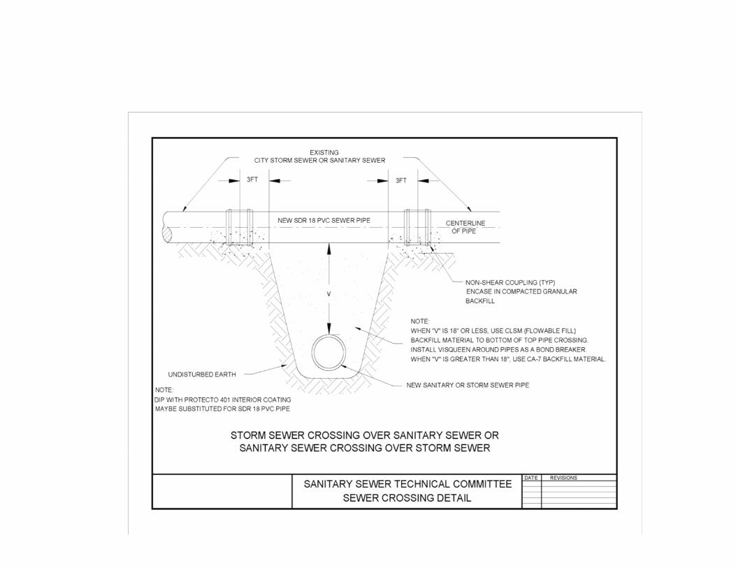
150.0 BACKFILL Where the inner edge of the trench is within 2-feet of the edge of the pavement, curb, gutter, curb and gutter, stabilized shoulder or sidewalk, the sewer trench must be backfilled with CLSM (controlled low strength material) meeting the approving authority’s specifications, or granular trench backfill, placed in uniform layers not exceeding 6 inches thick (loose measure) and compacted to 95% of Standard Proctor unless flowable fill is used, in which case, the fill shall be designed to have a compressive strength between 100 to 200 psi. Backfill requirements shall conform to agency with jurisdiction over right-of-way or easement where sewer is installed. Jetting and water-soaking is not allowed.
Outside of the pavement area, native soil may be returned to the trench, in accordance with the requirements of “STANDARD SPECIFICATIONS FOR WATER AND SEWER MAIN CONSTRUCTION IN ILLINOIS”, but the developer and/or contractor is responsible for repair of all settlement which occurs. 160.0 TESTING Testing shall comply with provisions of the “STANDARD SPECIFICATIONS FOR WATER AND SEWER MAIN CONSTRUCTION IN ILLINOIS latest edition” with the following exceptions: 1) the maximum leakage shall be 200 gpd/in. dia./day/mile of pipe instead of 240, 2) all reaches shall be tested, and 3) all manholes shall be vacuum tested in accordance with ASTM C1244-05a. 165.0 TELEVISING All newly constructed public and private sanitary sewers (excluding sewer laterals) shall be inspected by closed circuit television. The developer or property owner shall be responsible for the televising of new public and private sanitary sewers for 8-inch diameter or larger sewer.
Any defects discovered during televised inspection shall be corrected at no cost to the Approving Authority. After the correction of defects has been completed, affected sewer sections shall be re-televised at no cost to the Approving Authority. A copy of the internal pipe televising inspection shall be available to the approving authority for their review. An electronic copy of the televised inspections shall be provided on a media specified by the Approving Authority prior to final acceptance of the sewers. 170.0 MANDREL TEST The sewer must be capable of passing a two-foot long cylinder, which has a diameter 1 inch less than the inside diameter of the pipe being tested. 180.0 PAVEMENT REPAIRS Pavement repair requirements shall conform to agency with jurisdiction over right-of-way or easement where sewer is installed. 190.0 MINIMUM CONSTRUCTED SLOPE Pipe slopes shall be in accordance Section 370.320 of the ILLINOIS RECOMMENDED STANDARDS FOR SEWAGE WORKS. For terminal sewer runs serving less than one-hundred (100) population equivalents the sewer line for a minimum distance of 300-feet shall from the upstream manhole shall have a minimum pipe slope of 0.60% slope for an 8-inch diameter line.