sesiones técnicas midas genlatinamerica.midasuser.com/...analysis_gen_tutorial...sesiones técnicas...
TRANSCRIPT

Análisis y diseño de varios tipos de fundaciones
Latinamerica.midasuser.com
Sesiones Técnicas midas Gen
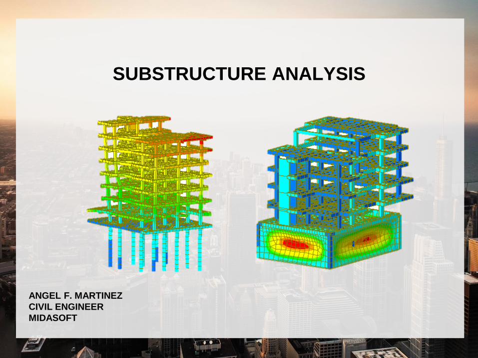
SUBSTRUCTURE ANALYSIS
ANGEL F. MARTINEZ
CIVIL ENGINEER
MIDASOFT
CONTENTS
1. FOOTING DESIGN
2. PILE RAFT ANALYSIS & DESIGN
3. BASEMENT WALL ANALYSIS & DESIGN

FOOTING DESIGN

Dimensions18m
21m
14m
18m
14m
2.8m
21m

Inspect Properties
• Material-Concrete ASTM C4000
• 3 rectangle Sections
• 1 thickness
H B
Column 0.45 m 0.6 m
Beam 0.4 m 0.35 m
Girder 0.3 m 0.2 m
Thickness
Wall 0.2 m
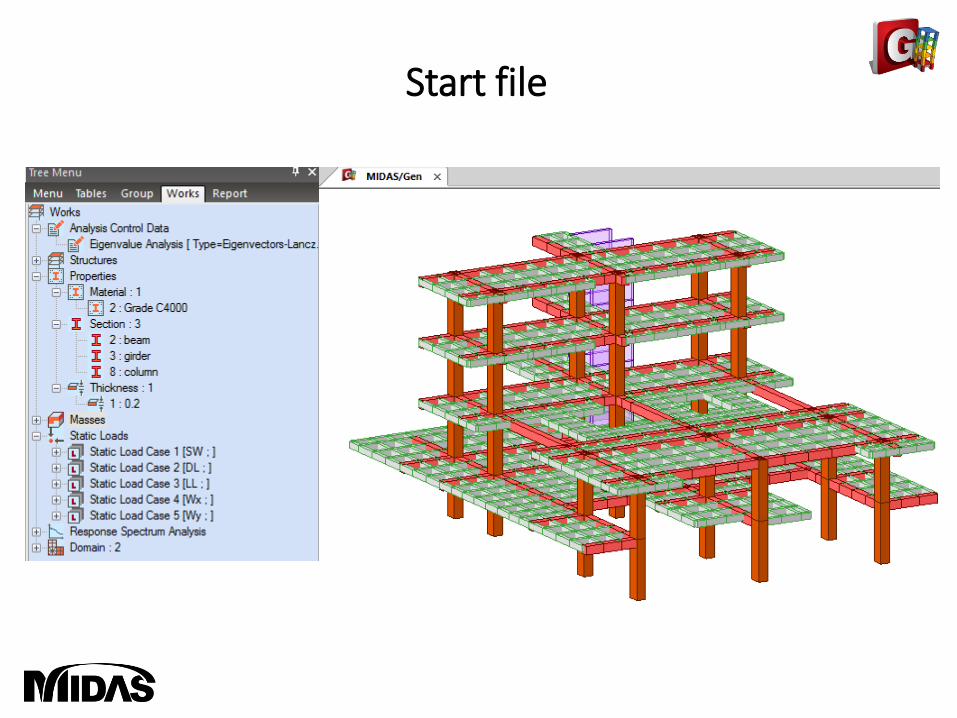
Start file

Boundary Conditions
• Assign fixed displacements SUPPORTS to bottom nodes (footing)

Perform Analysis

Results: Displacements

Results: Axial Forces

Results: Moments Y

Results: Reactions

Load combination
Generate Load ComboResults > Combinations > Concrete Design > Auto GenerationSelect Concrete Design and Footing DesignAuto GenerationDesign Code: ACI318-14 for both

Footing Design: CODE CHECK
Select Node 20• Enter allowable soil pressure : 300 kN/m^2• Rebar size #4 in X and Y• Surcharge Load 50 kN/m^2• CODE CHECK
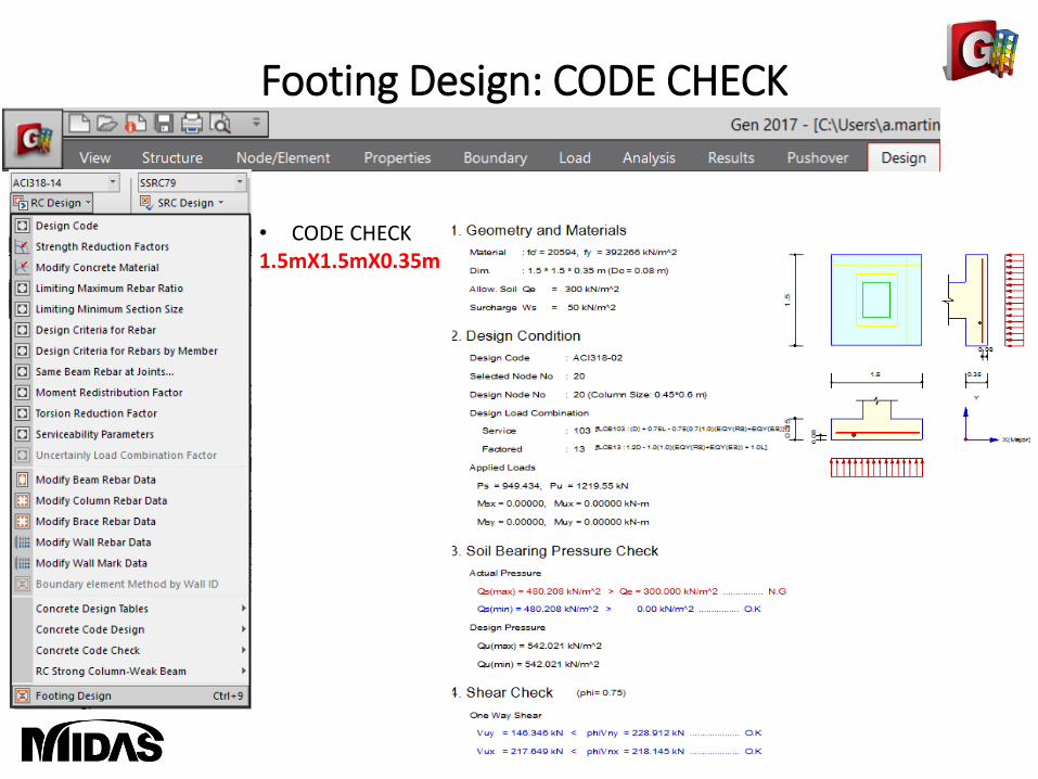
Footing Design: CODE CHECK
• CODE CHECK1.5mX1.5mX0.35m

Footing Design: AUTO DESIGN
Select Node 20• AUTODESIGN

Footing Design: AUTO DESIGN
• AUTO DESIGN2mX2mX0.4m

PILE RAFT ANALYSIS
& DESIGN

Dimensions
18m
20m
22m
10m
2.8m

Inspect Properties
• Material-Concrete ASTM C4000
• 6 rectangle Sections
• 2 thickness
H B
C30X70 0.3 m 0.7 m
V35X50 0.35 m 0.5 m
B20X50 0.2 m 0.5 m
N10X25 0.1 m 0.25 m
Pile D = 0.5 m
C45X70 0.45 m 0.7 m
Thickness
Wall 0.2 m
Raft 0.3 m

Start file

Extrude PilesSelect column nodes to extrude pilesSelect pile SectionExtrude -1m in dz 10 times

Auto-Mesh SlabSelect beams on the base by line elementsMesh size 1mThickness 0.3 m

Boundary Conditions
• Select Pile Spring Supports and apply to piles
Soil Type: SandGround Level: 0mUnit weight: 2 tonf/m^3Ko: 0.4Kh: 800 tonf/m^3Friction Angle: 30 degK1: Dense

Boundary Conditions
• Select Surface Springs and apply to raft
Point SpringKx: 80 tons/m^3Ky: 80 tons/m^3Kz: 800 tons/m^3

Perform Analysis

Results: Displacements

Results: Axial Forces

Results: Moments Y

Load combination
Generate Load ComboResults > Combinations > Concrete Design > Auto GenerationSelect Concrete Design Auto GenerationDesign Code: ACI318-14

Pile: Rebar Data
Select Piles• RC Design > Modify Column Rebar • Main #4• Ties/Spirals #3 @100
Add / Replace

Pile: Code Check
Select All Piles• RC Design• Concrete Code Check• Column Check

Pile: Code Check
1 member is NG: NOT GOODClick GRAPHIC to see PM Curve and details

Pile: Code Design
Run Pile/Column Design

Pile: Code Design
1. Click Re-CalculationPile rebar was redesigned based on code2. Click Update Rebar to see new rebar data created for pile

BASEMENT WALL ANALYSIS
& DESIGN

Dimensions
171 ft20m
14 m
19.6 m
5.6m
20m

Inspect Properties
• Material-Concrete ASTM C4000
• 4 rectangle Sections
• 2 thickness
H B
V35X50 0.35 m 0.5 m
B20X50 0.2 m 0.5 m
N10X25 0.1 m 0.25 m
C45X70 0.45 m 0.7 m
Thickness
Slab and Wall 0.2 m
Basement Wall 0.3 m

Start file

Extrude PilesSelect column and slab corner nodes to extrudeSelect C45x70 SectionExtrude -2.8m in dz 2 times
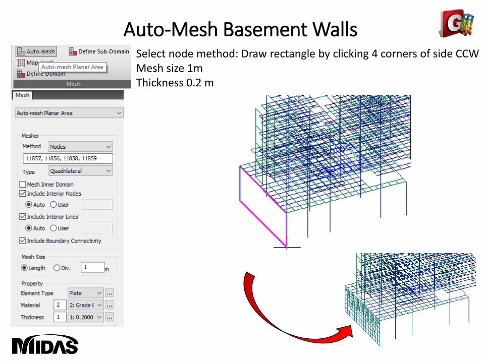
Auto-Mesh Basement WallsSelect node method: Draw rectangle by clicking 4 corners of side CCWMesh size 1mThickness 0.2 m

Auto-Mesh Basement WallsDraw rectangle by clicking 4 corners of remainnig sidesMesh size 1mThickness 0.2 m

Auto-Mesh SlabSelect 4 corner nodes of base as shownMesh size 1mThickness 0.3 m

Boundary ConditionAdd Spring SupportsElement Type: PlanarSpring Type: LinearKx = Ky = 80 Kz = 800 ton/m^3Select bottom raft

Boundary ConditionElement Type: PlanarSpring Type: Compression OnlyDirection: Normal +K = 800 ton/m^3Select basement walls in sequence

Basement Loads
Apply Hydrostatic PressureLoad Case: Water pressure loadSelect Basement walls-500kgf/m^3
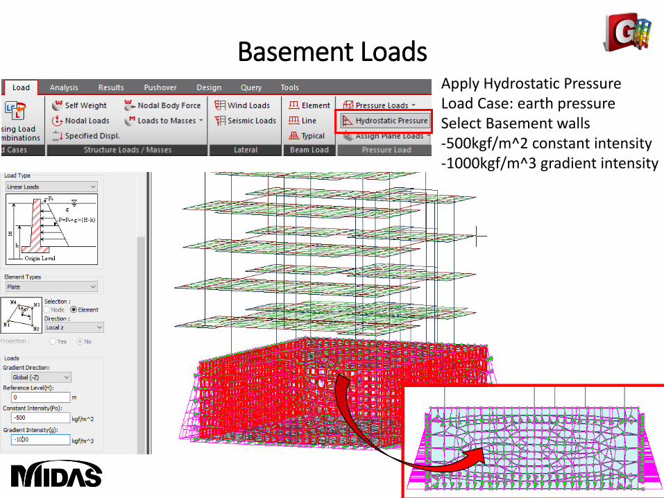
Basement LoadsApply Hydrostatic PressureLoad Case: earth pressureSelect Basement walls-500kgf/m^2 constant intensity-1000kgf/m^3 gradient intensity

Load combination
Generate Load ComboResults > Combinations > Concrete Design > Auto GenerationSelect Concrete and DesignAuto GenerationDesign Code: ACI318-14Add basement load combination: hydrostatic + earth pressure

Perform Analysis

Results: Deformations
Check Deformations

Results: Axial Plate Forces
Check Axial Forces

Results: Plate Stresses
Check Shear Stresses

Slab and wall load combinations
Slab/Wall Load Combination • Select the load combinations for the slab/wall element design.• Design > Design > Meshed Design > Slab/Wall Load
Combinations• Select the 1st load combination in each column to consider
during the slab/wall design.

Define Design Criteria for Rebar
Specify rebar size• Enter the standard sizes of rebars used in the design of reinforcement
for slab/wall elements.• Design > Design > Meshed Design> Design Criteria for Rebar• Check off [Basic Rebar for Slab]• For Slab Design:
Dir. 1 : 0.03 m, 0.03 m Dir. 2 : 0.05 m, 0.05 m
• For Wall DesignFace to Center Rebar 0.02m
v

Slab/Wall Rebar Checking Data
Specify rebar size• Select all 0.3m slab from tree menu• Layer Top Dir 1• Add Rebar 1: #3 @ 100• Add Rebar 2 #3• Add/Replace

Slab/Wall Rebar Checking Data
Specify rebar size• Select all 0.2m walls from tree menu• Layer Top Dir 1• Vertical 1: #3 @ 100mm• Horizontal 2: #3 @ 100mm• Add/Replace

Slab Flexural Design
Run DesignSelect Avg. NodalDir. 11. Select Rebar Ratio > Apply2. Click: Update rebar

Slab/Wall Rebar Checking Data
Rebar UpdateNew sets of reinforcement were automatically created for parts of slab

Slab Flexural Design

Slab Flexural Design

Slab Flexural Design

Slab Flexural Design

Slab Flexural Design

Slab Flexural Design

Wall Design
Run Design Specify Design Criteria1. Select Rebar Ratio > Apply2. Click: Update rebar

Wall Design

Wall Design

End