shearon harris nuclear power plant plant … · the normal service water system circulates water...
TRANSCRIPT

CAROLINA POWER & LIGHT COMPANY
SHEARON HARRIS NUCLEAR POWER PLANT
PLANT OPERATING MANUAL
VOLUME 6
PROCEDURE TYPE:
NUMBER:
TITLE:
PART 2
System Description (SD)
SD-139
Service Water System
HNP DC RECEIVED
'u•2 2 200
Page 1 of 31Rev- 12
R Reference
Use
SD-139
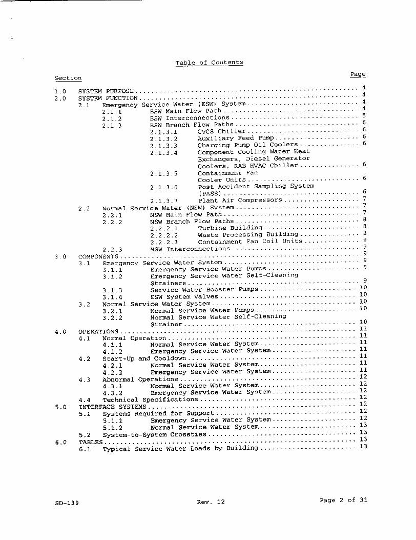
Table of Contents
Section Page
1.0 SYSTEM PURPOSE ............ ............................................ 4
2.0 SYSTEM FUNCTION ....... ................................................ 4
2.1 Emergency Service Water (ESW) System ............................ 4
2.1.1 ESW Main Flow Path .................................. 4
2.1.2 ESW Interconnections ................................ 5
2.1.3 ESW Branch Flow Paths ............................... 6
2.1.3.1 CVCS Chiller ............................ 6
2.1.3.2 Auxiliary Feed Pump ....................... 6
2.1.3.3 Charging Pump Oil Coolers ................ 6
2.1.3.4 Component Cooling Water Heat Exchangers, Diesel Generator Coolers, RAB HVAC Chiller ................ 6
2.1.3.5 Containment Fan Cooler Units ............................ 6
2.1.3.6 Post Accident Sampling System (PA SS ) .................................. 6
2.1.3.7 Plant Air Compressors ..................... 7
2.2 Normal Service Water (NSW) System ............................... 7
2.2.1 NSW Main Flow Path .................................. 7
2.2.2 NSW Branch Flow Paths ............................... 8
2.2.2.1 Turbine Building ........................ 8
2.2.2.2 Waste Processing Building ................ 8 2.2.2.3 Containment Fan Coil Units ............... 9
2.2.3 NSW Interconnections ................................ 9
3 .0 COMPONENTS ............................................................ 9
3.1 Emergency Service Water System .................................. 9
3.1.1 Emergency Service Water Pumps ......................... 9
3.1.2 Emergency Service Water Self-Cleaning Strainers ........................................... 9
3.1.3 Service Water Booster Pumps .......................... 10
3.1.4 ESW System Valves .................................. 10
3.2 Normal Service Water System .................................... 10
3.2.1 Normal Service Water Pumps ........................... 10
3.2.2 Normal Service Water Self-Cleaning Strainer ........................................... 10
4.0 OPERATIONS ........................................................... 11
4.1 Normal Operation ............................................... 11
4.1.1 Normal Service Water System ........................ 11
4.1.2 Emergency Service Water System ..................... 11
4.2 Start-Up and Cooldown .......................................... 11
4.2.1 Normal Service Water System ........................ 11
4.2.2 Emergency Service Water System ..................... 11
4.3 Abnormal Operations ............................................ 12
4.3.1 Normal Service Water System ........................ 12
4.3.2 Emergency Service Water System ..................... 12
4.4 Technical Specifications ....................................... 12
5.0 INTERFACE SYSTEMS .................................................... 12
5.1 Systems Required for Support ................................... 12
5.1.1 Emergency Service Water System ..................... 12
5.1.2 Normal Service Water System ........................ 13
5.2 System-to-System Crossties ..................................... 13
6.0 TABLES ............................................................... 13
6.1 Typical Service Water Loads by Building ........................ 13
Page 2 of 31Rev. 12SD-139

Table of Contents (continued)
Section P
7.0 FIGURES ......... ..................................................... 7.1 Emergency Service Water System, Train A ........................ 7.2 Emergency Service Water System, Train B ........................
7.3 Normal Service Water System .................................... 7.4 Service Water System Yard Piping ...............................
7.5 NSW Bearing Lubrication and Motor Cooling ......................
7.6 ESW Pump Seal/Bearing Water .................................... 8 .0 REFERENCES . ..........................................................
8 .1 Draw ings ....................................................... 8.1.1 System Drawings .................................... 8.1.2 Control Wiring Diagrams ............................ 8.1.3 SW System Component Instr. Schematics and
Logic Diagrams ..................................... 8.1.4 Manufacturer's Drawing .............................
8.2 Specifications ................................................. 8.3 Technical Manuals .............................................. 8.4 Other References ........................................ .......
SD-139 Rev. 12 Page 3 ol
age
15 16 17 18 19 20 21 22 22 22 23
27 27 28 29 30
f 31

1.0 SYSTEM PURPOSE
The Service Water System is made up of two separate systems, Lhe Emergency
Service Water System (ESWS) and the Normal Service Water System (NSWS). The
ESWS circulates water from the ultimate heat sink (UHS) through plant
components required for safe shutdown of the reactor following an accident,
and returns the water to the UHS. The ESWS performs its cooling function
following a loss-of-coolant accident (LOCA) or loss of off-site power,
automatically and without operator action. Redundancy built into the system
provides protection for a single active or single passive failure.
The ESWS also provides an emergency source of water for the Auxiliary
Feedwater System (AFWS), Essential Services Chilled Water System (ESCWS), and
the Fire Protection System (FPS).
The Normal Service Water System circulates water from the Cooling Tower (CT)
and Cooling Tower Makeup System through plant auxiliary components and back to
the Cooling Tower. The NSWS serves no safety function, but does provide
cooling water to the ESW headers during normal operation. NSW temperature is
influenced by lake water temperature due to continuous Cooling Tower Makeup.
The winter average temperature is in the sixties and the summer is in the
nineties.
2.0 SYSTEM FUNCTION
2.1 Emergency Service Water (ESW) System
The Emergency Service Water System consists of two intake structures (one on
the auxiliary reservoir and one on the main reservoir); two emergency service
water pumps, valves, and strainers; two emergency service water booster pumps;
two 30-inch diameter safety-related supply headers (A&B) with all associated
branches and heat exchangers; two safety-related return headers; and the
discharge structure for the return of water to the auxiliary reservoir. These
components are arranged into two completely independent redundant trains (A&B)
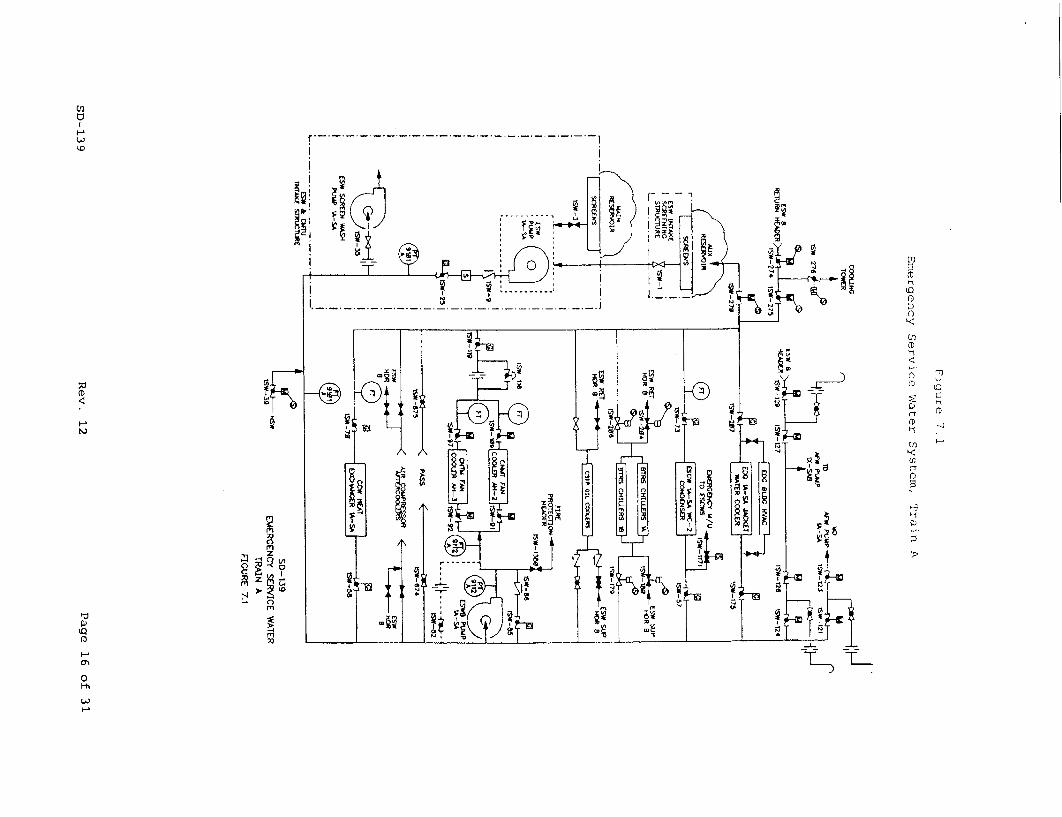
each capable of supplying sufficient cooling water for plant safety. Figures
7.1 and 7.2 provide simplified flow diagrams of the Emergency Service Water
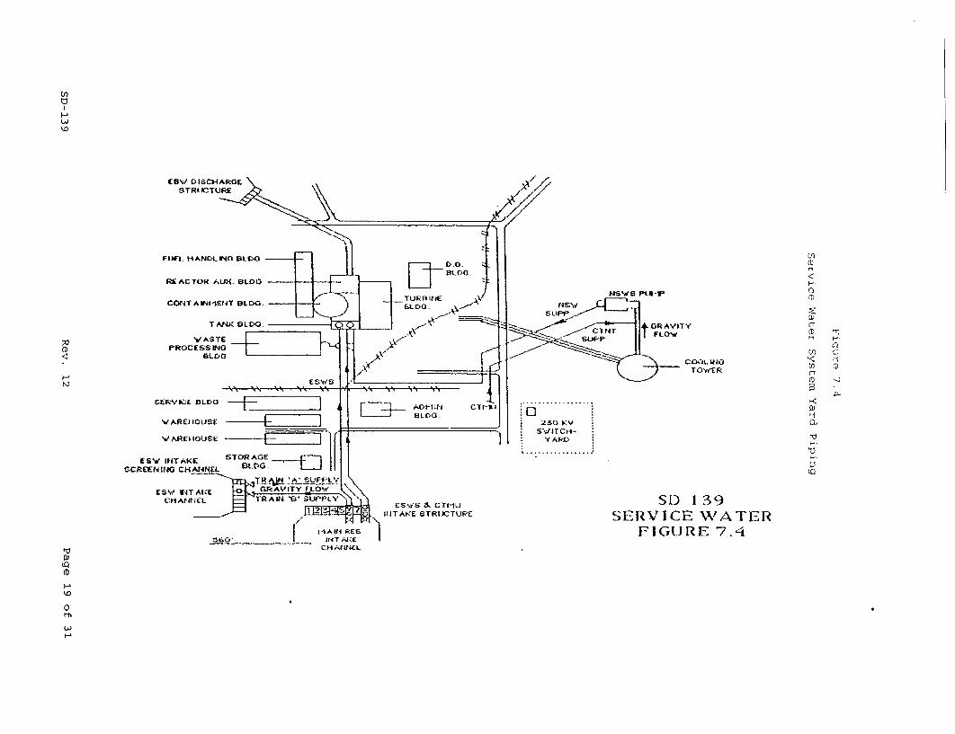
System and Figure 7.4 shows the general location of ESW yard piping.
2.1.1 ESW Main Flow Path
The water source to the Emergency Service Water (ESW] System originates from
the auxiliary reservoir (preferred source) or the main reservoir (backup
source). The preferred supply flows from the auxiliary reservoir through the
ESW intake canal to the ESW intake screening structure. As the water enters
the structure, the flow is divided by the structure into separate bays. In
each bay, the water flows through a trash rack and a traveling screen
(Reference SD-140) to remove debris greater than 7/16 inch, and through a
normally-open, manually-operated butterfly valve. The water exits the bay
through a 30-inch diameter coated (inside is epoxy paint, outside is coal tar)
steel pipe and gravity flows to the respective ESW pump bay in the ESW and
Cooling Tower Make-Up (CTMU) Intake Structure. The ESW backup source of water
flows from the main reservoir via the ESW and CTMU intake canal to the ESW and
CTMU Intake Structure where the flow is divided by the structure into bays.
Within each intake bay, the water flows through a trash rack and a finer
traveling screen as in the ESW intake screening structure. The main reservoir
Page 4 of 31Rev. 12SD-139

2.1.1 ESW Main Flow Path (continued)
water is stopped from flowing into the ESW pump suction bay by a normally
shut, manually-operated rectangular butterfly valve. The ESW pumps discharge
through a check valve and a self-cleaning strainer that removes debris larger
than 1/16 inch. During normal plant operation, the Normal Service Water
System supplies cooling water to heat loads on the Emergency Service Water
Header. The ESW pump discharge check valve prevents NSW System backflow
through the pump to the auxiliary reservoir. From the strainer, the water
exits the ESW and CTMU Intake Structure through underground 30-inch diameter
coated steel pipes (one pipe per safety train). The two supply headers enter
the tank building and drop down into the elevation 216' pipe tunnel that runs
the entire length of the reactor auxiliary building. Branch lines from supply
header A provide cooling water to all safety train A components. Similarly,
branch lines from supply header B provide cooling water to all safety train B
components. When the ESW System is required [safety injection signal
occurred, loss of off-site power, or cooling water inlet (auxiliary reservoir)
temperature <35°), both headers are supplied with water. Containment cooling
and auxiliary reservoir makeup requirements to avoid Tech Spec LCOs may result
in running both ESW pumps/trains during the summer months.
The heated water returns by branch lines to the train A or B return header
(30-inch diameter) located in the elevation 216' pipe tunnel. The headers
exit the plant area via motor-operated butterfly valves (lSW-270 and ISW-271)
and are routed underground to the ESW discharge structure. In addition to
supplying cooling water, the ESW System provides a source of water to the
Screen Wash System (SD-140) and is a backup source of water to the Essential
Chilled Water System, Auxiliary Feedwater System, and to the Fire Protection
System. Supply water to the Auxiliary Feedwater System can be controlled from
the Main Control Room.
Four 4" drain valves (gate) are provided on the ESW system for rapid draining
of the supply and return headers. These are ISW-1495, ISW-1496, ISW-1497, and
ISW-1498.
The ESW System alternate suction path from the main reservoir is the result of
NRC Regulatory Guide 1.27 requirements. Two 8' x 10', manually-operated
butterfly valves are located in the seismic Category 1 wall separating the
main reservoir intake from the Emergency Service Water pump chamber. In order
to shift suction, the 30-inch, manually-operated butterfly valves (lSW-l and
lSW-2) in the suction lines from the Auxiliary Reservoir and the 8' x 10,
valves (ISW-3 and ISW-4) from the Main Reservoir are repositioned. With both
suction valves in an ESW train open (lSW-l, 1SW-3 for "A" Train; ISW-2, 1SW-4
for "B" Train), water will flow from the Auxiliary Reservoir to the Main
Reservoir due to the difference in the reservoir levels.
2.1.2 ESW Interconnections
The ESW System's supply headers cannot be cross-connected. For example, ESW
Pump IA-SA cannot supply water to the B train supply header and vice versa.
Some components can be aligned to either header since, during normal
operation, only one emergency service header may be in service and is supplied
by the Normal Service Water System. Service water supply to the turbine
driven auxiliary feedwater pump is normally isolated, but may be aligned to
either header in the event of an emergency. The charging pump oil coolers
have their supply and return isolation valves aligned such that each pump is
supplied by only one service water train, A or B, depending on the respective
pump's electrical lineup. Valve alignment for the C charging pump depends on
its electrical lineup.
Page 5 of 31Rev. 12SD-139
2.1.3 ESW Branch Flow Paths
2.1.3.1 CVCS Chiller
The branch to the CVCS chiller contains air-operated valves that shut
automatically on a Safety Injection (SI) signal. Thus, during an emergency
this flow path would be isolated. During normal operation, the CVCS chiller
is aligned to only one train at a time.
2.1.3.2 Auxiliary Feed Pump
The turbine-driven auxiliary feed pump branch contains normally-shut, motor
operated valves. In the event Emergency Service Water is needed for auxiliary
feedwater, the control room operator would select which ESW header to use,
open the appropriate supply valves, and have an auxiliary operator shut the
associated loop seal line isolation valve. The valves from both headers would
not be opened at the same time since a piping failure on one service water
train could affect the flow in the other train.
2.1.3.3 Charging Pump Oil Coolers
The charging pump oil cooler branches contain only manual isolation valves.
These lines are sized (1/2 inch diameter) such that a failure of these lines
would not materially affect the service water flows to other components.
2.1.3.4 Component Cooling Water Heat Exchangers, Diesel Generator Coolers, RAB HVAC Chiller
The branch flow path from the A supply header to the component cooling heat
exchanger, diesel generator jacket water coolers, and auxiliary building HVAC
chiller condensers is independent of the B service water header. There are
manual butterfly isolation valves with this equipment.
2.1.3.5 Containment Fan Cooler Units
The branch flow path to the containment fan cooler units contains the service
water booster pump, which starts on an emergency (SI) signal. During normal
operation, service water flow bypasses the idle booster pump, enters
containment through the motor-operated butterfly isolation valves, flows
through the fan cooler coils and back to the ESW return header through the
containment isolation valves and a flow control orifice. This flow control
orifice has an air-operated, normally-open bypass valve in parallel such that
if the booster pump is off, the flow restriction is minimal. However, when
the booster pump starts, this valve shuts, forcing all the fan cooler return
flow through the orifice. The purpose of the booster pump and orifice is to
ensure that, during a design basis Loss of Coolant Accident, the service water
pressure inside containment is higher than containment pressure. This ensures
any leakage will be from service water into containment and will prevent the
release of containment radioactivity via the ESW System.
2.1.3.6 Post Accident Sampling System (PASS)
Branch flow from the A and B supply headers is supplied to the PASS. Manual
isolation valves are provided for the supply and return lines. Only one train
of supply and return valves (A or B train) may be open at any time to prevent
cross-connection of safety trains following an accident.
Page 6 of 31Rev. 12SD-139

2.1.3-7 Plant Air Compressors
Emergency Service Water can be aligned to supply cooling water to all three
plant air compressor aftercoolers. Either train can be aligned to supply the
air compressor aftercoolers with cooling water. When in Modes 1 through 4,
the ESW header supplying the air compressor aftercoolers is declared
inoperable. At no time should both trains be aligned to the air compressor
aftercoolers as this would cross connect the ESW headers.
2.2 Normal Service Water (NSW) System
The Normal Service Water System supplies cooling water from the cooling tower
basin and Cooling Tower Makeup System to various plant components and systems.
The Normal Service Water System consists of the intake structure, the
distribution header, two 100 percent capacity pumps, self-cleaning strainers,
motor-operated valves, and the supply and return headers to/from the Waste
Processing Building, Turbine Building, Reactor Auxiliary Building, and the
Containment Building. Figure 7.3 provides a flow diagram of the NSW system
and identifies the components supplied by NSW.
2.2.1 NSW Main Flow Path
Water from the cooling tower basin is supplied to the NSW intake chamber by a
6-foot diameter underground concrete conduit. The NSW intake chamber is
located north of the cooling tower. Additional water is supplied to this
conduit from a 3-foot diameter Cooling Tower Makeup Line. One of the two 100
percent capacity NSW pumps (design flow 50,000 gpm) takes suction on the water
in the chamber and pumps it through a motor-operated discharge valve and into
a 48-inch diameter steel pipe which contains a self-cleaning strainer. This
strainer is designed to filter debris down to 1/16-inch diameter and contains
isolation and bypass valves to allow maintenance without interruption of NSW flow.
From the strainer, the NSW flows through approximately 1200 feet of 4-foot
diameter steel pipe to the power block area of the plant where branch headers
go to the Turbine Building, Waste Processing Building, and the Reactor
Auxiliary Building. The NSW supply header in the Reactor Auxiliary Building
divides to supply the containment non-safety ventilation fan coil units and to
ESW safety train A and/or B supply header via a motor-operated isolation valve
to provide cooling water to the safety-related components in the Containment
Building (i.e., containment fan coolers) and in the Reactor Auxiliary
Building. The NSW System supply to ESW Safety train A and/or B is selectable
from the main control board in the control room.
During normal operation, the NSW return flows from the branch headers
(including the ESW header), with the exception of the Waste Processing
Building, are discharged into the circulating water return lines in the
Turbine Building north of the main condenser. The return flow from the Waste
Processing Building joins the circulating water lines in the yard between the
Turbine Building and the Cooling Tower.
Upon the start of an ESW Pump, the NSW supply to the ESW header (that will be
supplied by the running ESW Pump) is automatically isolated. In addition, the
return flow from the ESW header is automatically realigned to discharge to the
Auxiliary Reservoir instead of the Cooling Tower.
The general location of NSW System piping between the plant buildings and the
cooling tower is shown in Figure 7.4.
Page 7 of 31Rev. 12SD-139
2.2.2 NSW Branch Flow Paths
The NSW supply header splits into four major headers, the ESW supply header A
or B, the Turbine Building supply header, the Waste Processing supply header,
and the Containment Fan Coil units supply.
The branch flows from the ESW headers are as described in Section 2.1.3.
2.2.2.1 Turbine Building
The Turbine Building service water header is a 24-inch branch off the main 48
inch normal service water supply line. The branch flow paths to the larger
Turbine Building heat exchangers contain air-operated temperature control
valves that throttle the service water to maintain the shell side fluid at the
proper temperature. These loads are as follows:
1. Turbine Lube Oil Coolers
2. Turbine Generator Hydrogen Coolers
3. Hydrogen Seal Oil Unit
4. Air Compressor Aftercoolers (No air-operated TCV)
5. Generator Exciter Cooler
6. Turbine DEH Unit Coolers
There are also a number of small heat exchangers in the Turbine Building which
have manual throttle/isolation valves to control the service water flow.
These loads are as follows:
1. Condensate Pump Motor Oil Coolers
2. Condensate Booster Pump and Hydraulic Coupling Oil Coolers
3. Heater Drain Pump Motor Oil Coolers
4. Main Feed Pump Oil Coolers
5. Main Generator Bus Duct Cooling Unit
6. Condenser Vacuum Pump Heat Exchangers
The Turbine Building service water header also supplies makeup water to the
condensate polisher area evaporative air cooler.
2.2.2.2 Waste Processing Building
The Waste Processing Building service water header is a 24-inch branch off of
the main NSW supply line. The major flow demand on this header is the Waste
Processing Building closed Cooling Water heat exchanger. There is no
automatic temperature control of the shell side fluid of this heat exchanger.
Manual butterfly valves are provided for service water throttling/isolation.
The Waste Processing Building HVAC chiller condenser is also supplied with
service water cooling from this header. The service water components and
controls for this equipment are described in the Waste Processing Chilled
Water System Description (SD-146). The Waste Processing Building service
water header also supplies makeup water to the Waste Processing Building
evaporative air coolers.
Page 8 of 31Rev. 12SD-139

2.2.2.3 Containment Fan Coil Units
The branch flows to the Containment Fan coil units contain Containment isolation valves in both the supply and return lines. These valves are remote, air-operated, butterfly valves that automatically shut on a Phase A containment isolation signal.
2.2.3 NSW Interconnections
The NSW System provides a backup source of water to the ESW headers, as described in Section 2.1.1.
3.0 COMPONENTS
3.1 Emergency Service Water System
3.1.1 Emergency Service Water Pumps
The IA-SA and lB-SB Emergency Service Water Pumps are Ingersol-Dresser Model 35LKX-2. They are vertical-turbine, mixed-flow pumps with a closed-impeller arrangement involving two stages with single suction. Designed capacity is 20,000 gpm at 225 ft head; runout is 25,000 gpm at 140 ft; minimum recirculation is 7500 gpm at 300 ft; shut off head is equal to 360 ft. These pumps are nuclear safety class 3 and the motors are class IE. The motors are General Electric 6.9 KV, 1300 horsepower, 885 RPM induction type. Pumps lA-SA and IB-SB are powered from 6.9 KV Emergency Bus IA-SA CUB 9 and lB-SB CUB 1, respectively. The two pumps are located in the Emerency Service Water and Cooling Tower Makeup Intake Structure.
An unusual feature of these pumps is their setting length. The large difference in reservoir elevation [252' mean sea level (MSL) for the auxiliary reservoir and 220' MSL for the main reservoir] results in a total length from the suction bell to mounting flange of over 70 feet. Minimum submergence of 6 ft over the suction bell is required. The pump bearings are water-lubricated by the pumped fluid. A portion of the ESW screen wash flow is diverted through a cyclone separator to remove particles 100 microns and larger, and then supplied to the pump bearing and seal water system. Refer to OST 1214 & 1215 and calculation SW-0051, Attachment 5, for pump performance data.
3.1.2 Emergency Service Water Self-Cleaning Strainers
The two automatic self-cleaning strainers are nuclear safety class 3 and are manufactured by R. P. Adams Company. They are designed to continuously remove particles 1/16 inch in diameter or larger at a flow rate of 21,500 gpm at 150 psig at 140'F with a 5 psi differential. They are located inside the Emergency Service Water and Cooling Tower Makeup Intake Structure. Each unit is equipped with a controlled automatic strainer backwashing system capable of providing continuous or intermittent backwash of 650 gpm at 20 psid without interruption of the main flow stream. The IA-SA and lB-SB strainers are powered from 480V MCC-1A325A COMPT.1E and 480V MCC-lB32SB COMPT.IE, respectively.
Page 9 of 31SD-139 Rev- 19.
3.1.3 Service Water Booster Pumps
The Service Water Booster Pumps are Goulds Model 3405 12X14-12, single-stage, horizontal split case, double-suction, centrifugal pumps with a closed
impeller. Their design capacity is 4,250 gpm at 120 ft. head; minimum
recirculation is 750 gpm at 150 ft. head; runout is 6500 gpm at 74 ft. head
with a shutoff head of 170 ft; and design pressure is 225 psig. The pump is
nuclear safety class 3. Their motors, made by Siemens-Allis, are each rated
at 480 VAC, 200 horsepower, 1770 RPM, and are safety class IE. They are
located on the 236' elevation of the Reactor Auxiliary Building in the
vicinity of the component cooling heat exchangers. No special lubrication or
cooling systems are required for the pump or motor bearings. The booster
pumps IA-SA and IB-SB are powered from 480V Emergency Busses 1A2-SA and 1B2-SB, respectively. Refer to OST-1214 & 1215 and calculation SW-0051, Attachment 5, for pump performance data.
3.1.4 ESW System Valves
The majority of 4-inch and larger valves installed in ESW piping are carbon steel, lug-body butterfly valves, manufactured by Jamesbury Valve Company. However, several of the most critical valves have been replaced with stainless steel wafer type valves manufactured by Anchor/Darling. Some of the check valves have been replaced with stainless steel valves manufactured by Atwood & Morrill. For 2-inch and smaller diameter ESW piping, the majority of the valves are manufactured by Yarway or Rockwell International; these valves are predominantly globe valves.
3.2 Normal Service Water System
3.2.1 Normal Service Water Pumps
The Normal Service Water Pumps are Peerless Model 48HH and are not nuclear safety related. They are two-stage, vertical-turbine, mixed-flow pumps with closed impellers. The design capacity is 50,000 gpm at 203 ft. head; runout capacity is 72,000 gpm at 72 ft. head; the minimum continuous flowrate is 17,500 gpm (reference 8.4.1); and the minimum submergence is 8'3". The motors are induction motors made by Siemens-Allis and are rated at 6.6 KV, 3,000 horsepower, and 712 RPM. Two 100 percent capacity pumps are located on the Normal Service Water Intake Structure next to the Cooling Tower.
3.2.2 Normal Service Water Self-Cleaning Strainer
The NSW self-cleaning strainer is a Zurn Industries Model 596. Its design flow rate is 50,000 gpm at 150 psig at a temperature of 140°F. The maximum expected pressure differential across the 1/16-inch screen (clean)is 2.5 psid. The strainer is located outdoors on the NSW intake structure. The strainer is equipped with a controlled automatic strainer backwashing system capable of providing backwash of 1630 gpm without interrupting the main flow stream. The
strainer is backwashed on a timed cycle. The strainer will also be automatically backwashed between the timed backwashes if a high differential
pressure across the strainer is experienced. The backwash motor, made by General Electric, is rated at 480VAC, 2 horsepower, 1725 RPM, and has a final backwash shaft speed of 3.83 RPM.
Corrosion protection for the strainer internals is provided by sacrificial anodes. These anodes have been known to break loose and cause a clanking noise in the vicinity of the strainer.
Page 10 of 31Rev. 12SD-139
41.0 OPERATIONS
4.1 Normal Operation
4.1.1 Normal Service Water System
During normal plant operations the Normal Service Water System has one pump
supplying the Normal Service Water System and the Emergency Service Water
System. This pump supplies the Turbine Building, Waste Processing Building,
Containment Fan Coil units, and Emergency Service Water System headers.
4.1.2 Emergency Service Water System
During normal plant operations the Emergency Service Water System is in a
standby mode except as described in Section 2.1.1. The pumps are not running,
but the system headers and loads are lined up to be supplied by the NSWS.
Typically, both ESW headers are in service to minimize stagnant conditions and
provide chemical treatment for biological control. The supply and return
valves for the header(s) in service are open. If one ESW header is placed in
standby, the supply valve for the idle header is open and the return valve is
shut in order to keep the idle header pressurized.
4.2 Start-Up and Cooldown
4.2.1 Normal Service Water System
Most start-ups and cooldowns can be accomplished with the Normal Service Water
System supplying both Normal Service Water System and Emergency Service Water
System loads. However, if a rapid cooldown is desired (primary system), the
second Normal Service Water System Pump and the second safety-related service
water header must be placed in service. This is because two component cooling
water heat exchangers are needed and because flows through the other normal
service water loads are assumed to be close to the respective design flows.
Dry start-up of the NSW system requires special valve line-ups to avoid water
hammer damage. Current operating procedures require the isolation of the WPB
supply header, turbine generator exciter coolers, and turbine generator
hydrogen coolers. An automatic priming mode also helps prevent water-hammer.
This is initiated by taking the pump start switch to START and quickly
releasing. In this mode, the NSW pump discharge valve opens 10 percent for
seven minutes. After seven minutes the valve fully opens.
If one pump is already running at normal flow and pressure and the second pump
is to be started, the automatic priming mode may be bypassed by holding the
pump start switch in the START position. In this mode the discharge valve can
be taken full open, bypassing the seven-minute hold point.
Each NSW pump has "anti-pump" protection in the starting logic. Once the
control switch is taken to START (either in priming or in priming-bypass
mode), the sequence to close the pump breaker begins and cannot be restarted
for at least 15 seconds. Any attempt to restart the pump within the 15-second
period is blocked. This logic is intended to prevent multiple, rapid closures
of the pump breaker, such as might occur with a breaker fault.
4.2.2 Emergency Service Water System
During start-ups and cooldowns the Emergency Service water System remains in a
standby condition with Normal Service Water supplying the loads of the
Emergency Service Water headers. If a rapid cooldown of the primary systems
is desired, both A and B headers are placed in service to supply the two component cooling water heat exchangers.
Page 11 of 31Rev. 12ýqD-139

4.3 Abnormal Operations
4.3.1 Normal Service Water System
Whenever service water temperature exceeds 90'F, all four containment fan
coolers are placed in service. The second Normal Service Water Pump may be needed if the other loads are drawing close to design flows. The second Emergency Service Water Header must be placed in service due to the containment fan coolers. Loss of normal service water will result in plant shutdown due to loss of cooling to essential secondary components.
4.3.2 Emergency Service Water System
This safety-related system is required to be operable to support cooling requirements following an accident (LOCA, loss of off-site power). If this should happen the Emergency Service Water System will isolate from the Normal Service Water System, the pumps start automatically, and valves cycle to their safeguards positions.
The Technical Specification Minimum Main Reservoir level is 215 feet. This limit is to insure that all components are capable of their design basis heat removal capacities.
If the Emergency Service Water intake water temperature falls below 35"'F, the Emergency Service Water pumps should be started to minimize the potential for icing the Emergency Service Water intake.
The Emergency Service Water pumps and booster pumps are operated on a periodic basis to ensure proper flows in accordance with the Technical Specifications surveillance requirements.
It should be noted that nearly all of the ESW heat loads do not contain automatic throttling valves for temperature control of the shell side fluid. This situation makes it necessary to conduct a flow balance to determine the position of the manual heat exchanger outlet valves, such that proper service water flows are maintained in the system
4.4 Technical Specifications
At least two independent Emergency Service Water loops shall be OPERABLE.
5.0 INTERFACE SYSTEMS
5.1 Systems Required for Support
5.1.1 Emergency Service Water System
The following systems are required for support of the Emergency Service Water System:
1. Instrument Air for valve operation
2. Emergency Service Water Screen Wash System and Emergency Service Water Traveling Screens
3. Reservoirs, Intake Canals and Structures, Discharge Canals and Structures
4. Various electrical systems
Page 12 of 31SD-139 Rev. 12
5.1.2 Normal Service Water System
The following systems are required for support of the Normal Service Water
System:
1. Instrument Air for valve operation
2. Potable Water for pump bearing and seal flushing
3. Circulating Water for return of the service water to the cooling towers
4. Cooling Tower and Cooling Tower Makeup System
5. Various electrical circuits and panels
5.2 System-to-System Crossties
The ESW System is cross-connected with the NSW System, the Auxiliary Feedwater
System, and the Fire Protection System.
6.0 TABLES
6.1 Typical Service Water Loads by Building
Page 13 of 31SD-139 Rev- 12
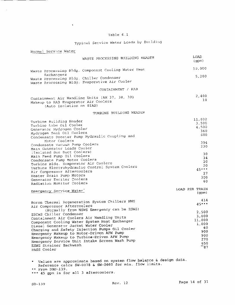
Table 6. 1
Typical Service Water Loads by Building
Normal Service Water
WASTE PROCESSING BUILDING HEADER LOAD (gpm)
Waste Processing Bldg. Component Cooling Water Heat 10,000
Exchangers Waste Processing Bldg. Chiller Condenser 5,200
Waste Processing Bldg. Evaporative Air Cooler
CONTAINMENT / RAB
Containment Air Handling Units (AH 37, 38, 39) 2,400
Makeup to RAB Evaporator Air Coolers 10
(Auto Isolation on SIAS)
TURBINE BUILDING HEADER
Turbine Building Header 11,032
Turbine Lube Oil Cooler 3,500
Generator Hydrogen Cooler 4,500
Hydrogen Seal Oil Coolers 360
Condensate Booster Pump Hydraulic Coupling and 600
Motor Coolers
Condensate Vacuum Pump Coolers 354
Main Generator Leads Cooler 230
(Isolated Bus Duct Coolers) Main Feed Pump Oil Coolers 30
Condensate Pump Motor Coolers 34
Turbine Bldg. Evaporator Air Coolers 20
Turbine Electrohydraulic Control System Coolers 20
Air Compressor Aftercoolers 45***
Heater Drain Pump Motors 27
Generator Exciter Coolers 300
Radiation Monitor Coolers 60
EmergencyService Water* LOAD PER TRAIN (gpm)
Boron Thermal Regeneration System Chillers NNS 414
Air Compressor Aftercoolers 45*
(Normally from NSWS Emergency can be ESWS)
ESCWS Chiller Condenser 2,500
Containment Air Coolers Air Handling Units 3,000
Component Cooling Water System Heat Exchanger 11,000
Diesel Generator Jacket Water Cooler 1,000
Charging and Safety Injection Pumps Oil Cooler 60
Emergency Makeup to Motor-Driven AFW Pump 900
Emergency Makeup to Turbine-Driven AFW Pump 900
Emergency Service Unit Intake Screen Wash Pump 270
ESWS Strainer Backwash 650
PASS Cooler 87
* Values are approximate based on system flow balance & design data.
Reference calcs SW-0078 & SW-0080 for min. flow limits.
** From DBD-139. 2 45 gpm is for all 3 aftercoolers.
SD-139 Rev. 12 Page 14 of 31
7.0 F IGURES
7.1 Emergency Service Water System, Train A
7.2 Emergency Service Water System, Train B
7.3 Normal Service Water System
7.4 Service Water System Yard Piping
7.5 NSW Bearing Lubrication and Motor Cooling
7.6 ESW Pump Seal/Bearing Water
Page 15 of 31Rev. 12SD-139
H
CD
H
L<
co 'CD
rr
cv
M
V) 0
-L
CD
H
0��
0 ht�
H
T-) T-

-1 rl)
LW 0
r-4
a4
CN
,ql
r:
ý4
Li Cý
z uj

Figure 7.3
Normal Service Water System
FO RAB (NNS)•
RETURN TO
vIA CIRCULATING WATER
* TYPICAL FOR 3 COMPRESSORS
WATER HEA• BR
S*/WATR HOEDER 8SO
AFTER COOLIERZ
__ • CONDENSER• VACUUM P'UMPS
NE.AT DcCAANGER
-• • FEED PUMP MOTORIN"I:I13
ITýUJRBINE ,,H1 uN'ITI1111
COOLERS
~P HST DRAIN
ý PUMP SX AND WOTORý ý
STURBINE LU, 1 Oýiii 1 1 ,
S~~GENERATOR H YDROGEF.N
COOLERS
SGENERATOR HYROE
COOLER
"Cy ECOOLERS
COOI
S~CONOENSATE BOOSTER PUMPS & H`YDAUJL1C
COUPLING OILCOLR
EVAP TOR AIR COOLER ER-9
SML PANELS
2. SEC SAMPLE 3. SIEC STEAM SlAMPLE
SRAD SMOBUOG
CONNECTIONS FOR
sw CHEM E E LT -
-TO RA WFADER (NNS)
t cCW MX 2. IWAC •rL.CN 3. EVAP A IRC
S INTAKESTUCUR
MOR[oUL SECE WATER PUMPS
Page 18 of 31
&
SD-139 Rev. 12
(SV DIScHAROE\ STRUTURE Z<D,
FUEWL H-tANb1L ~IN RLD43
RE ACTOR o;UtX. BLDOC
C04IT A t-U lrt-IT DLODG.
TAM( ELDG,
VASY E PROCESSIZO
6LD0
srr~k.c BLDG fIO ~ i~ V AREI LOUSE *E1111
It/-EZZZIIOiS fS'df ,ETiKE STOR AGE
SCREENINGri CH-AfSJEL BLDG.
CIIANN-EL E-ýR A 114'S'SUeI'LV
7
ttsld'S PtLNU'
20V SN/ITCH
Y ARC,
ES'j*S a CTl~jU 111T AKE %STRUCTUPE
C OCL WAG T OWE R
SI) 139 SERVICE WNATER
FIGURE 7ACH- AN NEL
LQ
0
rn
w
CD
H N,
H
CA
C!) (D
Q

Figure 7.5
NSW Bearing Lubrication and Motor Cooling
0 zo ai3 0
I _. 0
Page 20 of 31Rev. 12SD-139
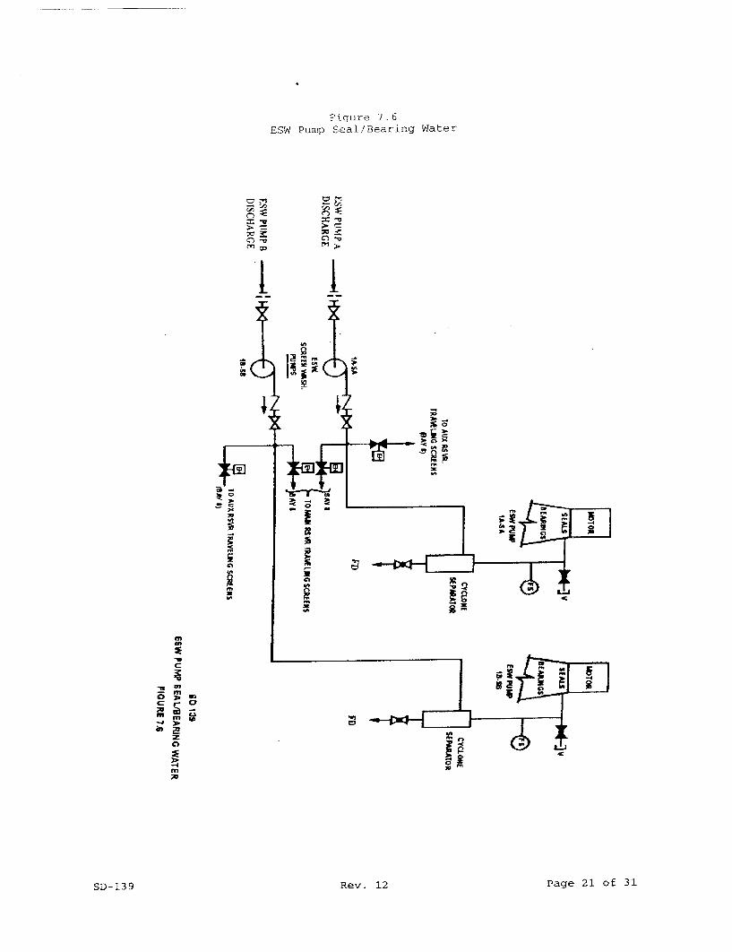
Figure 7.6 ESW Pump Seal/Bearing Water
Lii
i~is
UT,
m
Page 21 of 31
p
Rev. 12SD-139
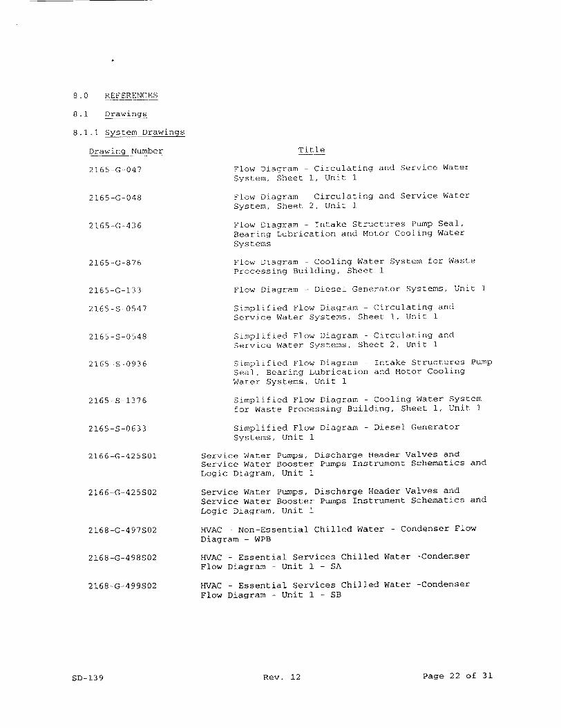
8.0 REFERENCES
8.1 Drawings
8.1.1 System Drawings
Drawing Number
2165-G-047
2165-G-048
2165-G-436
2165-G-876
2165-G-133
2165-S-0547
2165-S-0548
2165 S-0936
2165-S-1376
2165-S-0633
2166-G-425S01
2166-G-425S02
2168-G-497S02
2168-G-498S02
2168-G-499S02
SD-139
Title
Flow Diagram - Circulating and Service Water System, Sheet 1, Unit 1
Flow Diagram - Circulating and Service Water System, Sheet 2, Unit 1
Flow Diagram - Intake Structures Pump Seal, Bearing Lubrication and Motor Cooling Water Systems
Flow Diagram - Cooling Water System for Waste Processing Building, Sheet 1
Flow Diagram - Diesel Generator Systems, Unit 1
Simplified Flow Diagram - Circulating and Service Water Systems, Sheet 1, Unit 1
Simplified Flow Diagram - Circulating and Service Water Systems, Sheet 2, Unit 1
Simplified Flow Diagram - Intake Structures Pump Seal, Bearing Lubrication and Motor Cooling Water Systems, Unit 1
Simplified Flow Diagram - Cooling Water System for Waste Processing Building, Sheet 1, Unit 1
Simplified Flow Diagram - Diesel Generator Systems, Unit 1
Service Water Pumps, Discharge Header Valves and Service Water Booster Pumps Instrument Schematics and Logic Diagram, Unit 1
Service Water Pumps, Discharge Header Valves and Service Water Booster Pumps Instrument Schematics and Logic Diagram, Unit 1
HVAC - Non-Essential Chilled Water - Condenser Flow Diagram - WPB
HVAC - Essential Services Chilled Water -Condenser Flow Diagram - Unit 1 - SA
HVAC - Essential Services Chilled Water -Condenser Flow Diagram - Unit 1 - SB
Rev. 12 Page 22 of 31

8.1-2 Control Wiring Diagrams
Drawing Number
2166 B 401
2181
2182
2183
2185
2186
2188
2189
2190
2191
2192
2197
2198
2199
2201
2202
2207
2208
2211
2212
2213
2216
2217
2220
Tit le
Sheet
NSW Pump lA-NNS Sheet 1
NSW Pump IB-NNS Sheet 1
NSW Pumps Instrumentation
NSW Pump 1A Dischg. Valve 7SW-B37-1
NSW Pump lB Dischg. Valve 7SW-B38-1
NSW Pumps Strainer 7SW-S23-1 & Va. 7SW-HI-I
NSW Pump IA-NNS Sheet 2
NSW Pump 1B-NNS Sheet 2
NSW Seal & Brg. Clg Wtr Booster Pump IA-NNS
NSW Seal & Brg. Clg Wtr Booster Pump 1B-NNS
Exciter Cooler Outlet Valve (TCV 0951)
Hydrogen Cooler Outlet Valve (TCV-0950)
H2 Seal Oil & DEH Cooler Instrumentation
Turbine Lube Oil Coolers Outlet Valve (TCV-4750)
Turbine Gen. Cooler Valves Indication
NSW Supply Hdr "A" Isol. Valve 3SW-B5SA-1
NSW Supply Hdr "B" Isol. Valve 3SW-B6SB-I
ESW Pump lA-SA
ESW Pump IB-SB
ESW Punps Instrumentation
ESW Pump IB-SB Inlet Va. - Main Reservoir - 3SW-B4SB-1 & Aux. Reservoir 3SW-B2SB-I
ESW Pump lA-SA Inlet Va. - Main Reservoir - 3SW-B3SA-1
& Aux. Reservoir 3SW-BlSA-1
Main Reservoir Level Instrumentation
Page 23 of 31Rev. 12SD-139

8.1.2 Control Wiring Diagrams (continued)
Drawing Number
Sheet
2221 ESW Pump IA-SA St
2222 ESW Pump lB-SB St
2223 ESW Pump IA-SA Di
2224 ESW Pump lB-SB Di
2227 Service Water Sys
2228 Service Water Sys
2229 Service Water Sys
2231 Service Water Sys
2232 Service Water Sys
2233 Service Water Boc
2234 Service Water Boc
2235 Service Water Boc & Flow)
2237
2241
2242
2245
2246
2247
2248
Title
rainer 3SW-S21SA-I & Valve 3SW-H2SA-1
rainer 3SW-S22SB-1 & Valve 3SW-H3SB-l
schg. Valve 3SW-B7SA-I
.schg. Valve 3SW-B9SB-1
". A" Misc. Alarms Sh. 1
""B" Misc. Alarms Sh. 2
"A" & "B" Misc. Alarms, Sh. 3
tem "A" Misc. Alarms, Sh. 4
"B" Misc. Alarms, Sh. 5
ster Pump lA-SA
ster Pump lB-SB
ster Pumps Instrumentation {Pressure
Contmt. Service Water "A" & "B" Return Orifice Bypass Valves 3SW-B64SA-1 & 3SW-B65SB-1
Serv. Water from Containment Fan Coolers AH-2 (SA) & AH-3 (SA) Instrumentation
Serv. Water from Containment Fan Coolers AH-I (SB) & AH-4 (SB) Instrumentation
Serv. Water to Containment Fan Cooler AH-3 Inlet Valve 2SW-B46SA-1
Serv. Water from Containment Fan Cooler AH-3 Outlet Valve 2SW-B47SA-1
Service Water to Containment Fan Cooler AH-2 Inlet
Valve 2SW-B45SA-l
Service Water from Containment Fan Cooler AH-2 Outlet Valve 2SW-B49SA-I
Page 24 of 31Rev. 12SD-139
8.1.2 Control Wiring
Drawing Number
Sheet
2249
2250
2251
2252
2253
2254
2255
2257
2258
2259
2260
2261
2262
2263
2264
2267
Diagrams (continued)
Title
Service Water to Containment Fan Cooler AH-1 Inlet Valve 2SW-B52SB-1
Service Water from Containment Fan Cooler AH-1 Outlet Valve 2SW-B48SB-l
Service Water to Containment Fan Cooler AH-4 Inlet Valve 2SW-BSlSB-1
Service Water from Containment Fan Cooler AH-4 Outlet Valve 2SW-B50SB-I
Service Water to Containment Fan Coil Units Isol. Va. 2SW-B88SAB-I
Service Water Return from Containment Fan Coil Units rsol, Valve 2SW-B89SA-l
Service Water Return from Containment Fan Coil Units Isol. Valve 2SW-B90SB-l
Hdr. "A" Service Water Backup to AFWP IX-SAB Supply Valve 3SW-B70SA-I
Hdr. "A" Service Water Backup to AFWP lX-SAB Supply Valve 3SW-B7lSA-I
Hdr. "B" Service Water Backup to AFWP IX-SAB Supply Valve 3SW-B73SB-l
Hdr. "B" Service Water Backup to AFWP IX-SAB Supply Valve 3SW-B72SB-1
SW Backup to AFWP IA-SA Supply Valve 3SW-B75SA-I
SW Backup to AFWP IA-SA Supply Valve 3SW-B74SA-I
SW Backup to AFWP lB-SB Supply Valve 3SW-B77SB-1
SW Backup to AFWP IB-SB Supply Valve 3SW-B76SB-1
SW to & from Component Clg. Wtr. HX "A" Instr. & Alarms
Page 25 of 31SD-139 Rev. 12
8.1.2 Control Wiring Diagrams (continued)
Drawing Number Title
Sheet
2268 SW to & from Component Clg. Wtr. HX "B" Instr. &
Alarms
2272 Serv. Wtr./CVCS Chiller Isolation Valves 3SW-V266SA-I
& 3SW-V237SA-1
2273 Serv. Wtr./CVCS Chiller Isolation Valves 3SW-V267SB-I & 3SW-V238SB-1
2280 "A" Service Water Hdr. Return to Normal Service Water
Hdr. 3SW-B13SA-l
2282 "B" Service Wtr. Hdr. Return to NSW Hdr. 3SW-Bl4SB-1
2284 Reactor Aux. Bldg. Return SW Main Hdr. Isolation Valve
3SW-B8SB-1
2286 Service Water Return Hdr. A Shutoff Valve to Aux.
Reservoir 3SW-Bl5SA-I
2287 Service Water Return Hdr. B Shutoff Valve to Aux. Reservoir 3SW-BI6SB-1
2290 Service Water Manual Return Valve 7SW-B53-1 Indication
2451 Air Compressor IA-NNS
2598 Chiller WC-2 (IA-SA) Chilled Water Alarms, Sh. 1
2599 Chiller WC-2 (IB-SB) Chilled Water Alarms, Sh. 1
2601 Chiller WC-2 (IA-SA) Compressor, Sh. 1
2605 Chiller WC-2 (lA-SA) Condenser Water Recirculating Pump P7 (lA-SA)
2612 Chiller WC-2 (lA-SA) Condenser Water Supply Valve 3SWB300SA-1
2617 Water Chiller WC-2 (IA-SA) Emergency Makeup Water
Supply Valve 3SW-V868SA-l
Page 26 of 31Rev. 12SD-139
8.1.3 SW System Component InsLr. Schematics and Logic Diagrams
Drawing Number
2166-B-430
13.1
13.2
13.3
21.1
21.2
21.3
21.4
21.5
21.7
21.12
8.1.4 Manufacturer's Drawing
Drawing Number
1364-3957
1364-4553
1364-5229
1364-5899
1364-4010
1364-4009
1364-6431
1364-4178
1364-4761
1364-2127
1364-3189
1364-1996
Title
Sheet
DEB & Lube Oil Coolers
Hydrogen Seal Oil Coolers
Hydrogen & Exciter Coolers
Serv. Wtr. for Aux. F. Wtr. Pumps
Serv. Wtr. to & from Comp. Clg. Wtr. HX
Serv. Wtr. to & from Containment Fan Coolers AH-2&3
Serv. Wtr. to & from Containment Fan Coolers AH-I&4
Serv. Wtr. to & from Air Compressors & Aftercoolers
Serv. Wtr. to & from Containment Fan Coil Units
Serv. Wtr. to Aux. Bldg HVAC Chillers WC-2
Title
ESW Self-Cleaning Strainer Control Panel
Dresser Instruments - Thermometer, Model 50EI60E
Masoneilan Int'l Pneumatic Actuator Models 33-37310 & 8005A
Valtek - Mark I Valve Actuators
Rosemount - Pressure Transmitter, Model 1153B
Rosemount - Temperature Transmitter, Model 444
Weed Instr. - Thermocouple Type E4B250G-(L)AS
Mercoid - Pressure Switch Model DAW-7043-804B
Mercoid Pressure SW Diff.,
Model DPAW-7033-804B
Versa Pac Motor Outline - NSW Pump
Siemens-Allis - SW Bstr. Pump
Weston - Temperature Gage, Models 4300 & 4310
Page 27 of 31Rev. 12SD-139
8.1.4 Manufacturer's Drawing
Drawing Number
1364-16589
1364-2900
1364-5201
1364-41808
1364-4763
1364-96530,SO1,S02
1364-96531,S01,S02
1364-7370
1364-43477
1364-43475
1364-43476
1364-96537
1364-45840
1364-45839
1364-98013
1364-98014
(continued)
Title
General Electric - ESW Pump Motor
Jamesbury Valve - 30" Wafer Sphere 1504 Flanged
Pyco - Temperature Gages Model 23-7156
United Electric - Press. Diff. SW Model J27KB
Pyco - Temperature Ind. SW. - Model 23-7148
Anchor/Darling Valve - 30" Wafer Butterfly, 150#
Anchor/Darling Valve - 36" Wafer Butterfly, 150#
ESW Pump General Arrangement Dwg.
ESW Pump Cross-Sectional Dwg.
ESW Pump BOM
ESW Pump Spare Parts
ESW Pump Lower Seismic Support
ESW Pump IA-SA Performance Curve
ESW Pump IB-SB Performance Curve
Wafer Check Valve 14 inch 150 LB. SS
Wafer Check Valve 30 inch 150 LB. SS
Notes:
1. The drawing number listed is not applicable to all applications of the instrument in the Service Water System. Consult the Instrument List for
the applicable EMDRAC drawing number.
8.2 Specifications
Specification No.
IN-01
IN-03
IN-04
IN-07
Title
Electronic Instrumentation
Orifices
Thermocouple Assemblies
Local Pressure Gages
Page 28 of 31Rev. 12SD-139
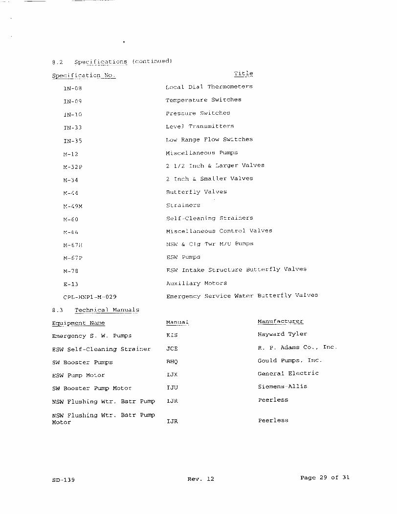
8.2 Specifications (continue
Specification No.
IN-08
IN-09
IN-10
IN-33
IN-35
M-12
M-32P
M-34
M-44
M-49M
M-60
M-66
M-67H
M-67P
M-78
E-13
CPL-HNPl-M-029
8.3 Technical Manuals
Equipment Name
Emergency S. W. Pumps
ESW Self-Cleaning Strainer
SW Booster Pumps
ESW Pump Motor
SW Booster Pump Motor
NSW Flushing Wtr. Bstr Pump
NSW Flushing Wtr. Bstr Pump Motor
Title
Local Dial Thermometers
Temperature Switches
Pressure Switches
Level Transmitters
Low Range Flow Switches
Miscellaneous Pumps
2 1/2 Inch & Larger Valves
2 Inch & Smaller Valves
Butterfly Valves
Strainers
Self-Cleaning Strainers
Miscellaneous Control Valves
NSW & Clg Twr M/U Pumps
ESW Pumps
ESW Intake Structure Butterfly Valves
Auxiliary Motors
Emergency Service Water Butterfly Valves
Manual
KIS
JCE
BHQ
IJX
IJU
IJR
Manufacturer
Hayward Tyler
R. P. Adams Co., Inc.
Gould Pumps, Inc.
General Electric
Siemens-Allis
Peerless
PeerlessIJR
Page 29 of 31Rev. 12SD-139
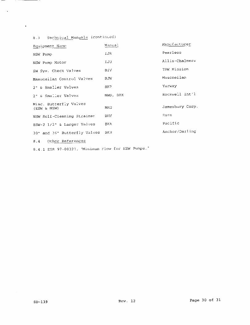
8.3 Technical Manuals (continued)
Equipment Name Manua
NSW Pump IJR
NSW Pump Motor 1IJU
SW Sys. Check valves BIV
Masoneilan Control Valves BSY4
2" & Smaller Valves BKP
2" & Smaller Valves NWD,
Misc. Butterfly Valves (ESW & NSW) BKG
NSW Self-Cleaning Strainer BHY
ESW-2 1/2- & Larger Valves BKA
30" and 36" Butterfly Valves BKB
8.4 Other References
8.4.1 ESR 97-00321, 'Minimum Flow f
Manufacturer
Peerless
Allis-Chalmers
TRW Mission
Masoneilan
Yarway
Rockwell Int'l
Jamesbury Corp.
Zurn
Pacific
Anchor/Darling
BKK
or NSW Pumps."
Page 30 of 31Rev. 12SD-139
Revision Summary
Revision 12 Revised per ESR 99-00145
Page 31 of 31Rev. 12SD-139