sil 2 quadruple repeater power supply din-rail and
TRANSCRIPT

D5212 - SIL 2 Quadruple Repeater Power Supply G.M. International ISM0361-4
SIL 2 Quadruple Repeater Power Supply DIN-Rail and Termination Board
Model D5212Q
D5212Q
INSTRUCTION MANUAL

D5212 - SIL 2 Quadruple Repeater Power Supply G.M. International ISM0361-4 2
General Description: The quadruple channel Repeater Power Supply D5212Q provides a fully floating DC supply for energizing conventional 2-wire 0/4-20 mA transmitters located in Hazardous Area, and repeats the current in Safe Area to drive a load in applications requiring SIL 2 level (according to IEC 61508:2010) in safety related systems for high risk industries.
Function: 4 channels I.S. analog input for 2-wire loop powered transmitters (or separately powered inputs, only for channels 1 and 2), providing isolation between input, output and supply, and current source output signals. The module is fully configurable to achieve any desired input/output combination: any number of outputs can be independently linked to each input. Output function can be configured as: adder, subtractor, low/high selector. An optically coupled open-drain alarm output with user-settable trip point is also provided. Modbus RTU RS-485 output is available on Bus connector to interface digital device.
Configurability: Totally software configurable (no jumpers or switches), by PC via USB with PPC5092 adapter and related configurator software or by RS485 Modbus output, in order to choose: input signal range, linear or reverse output signal, alarm trip point, low, high, window or fault repeater alarm mode, hysteresis, delay time. Mounting on standard DIN-Rail, with or without Power Bus, or on customized Termination Boards, in Safe Area or in Zone 2.
Technical Data
Characteristics
Supply: 24 Vdc nom (21.5 to 30 Vdc) reverse polarity protected, ripple within voltage limits ≤ 5 Vpp, 2 A time lag fuse internally protected. Current consumption @ 24 V: 200 mA max. with 20 mA input/output for 4 channels. Power dissipation: 2.75 W max. with 24 V supply voltage and 20 mA input/output for 4 channels.
Isolation (Test Voltage): I.S. In/Out 1.5 KV; I.S. In/Supply 1.5 KV; Out/Supply 500 V; I.S. In/Alarm 1.5 KV; Supply/Alarm 500 V; Out/Alarm 500 V.
Input: 0/4 to 20 mA (2 wire Tx current limited at ≈ 25 mA) and separately powered inputs (only for channels 1 and 2).
Transmitter line voltage: 14.5 V typical at 20 mA with max. 20 mVrms ripple, 14.0 V minimum. Integration time: 500 ms. Resolution / Visualization: 1 μA.
Fault: Out-of-range (burnout) fault detection can be enabled or disabled. Any analog output can be programmed to detect fault condition forcing downscale or highscale. Alarm can be programmed to detect fault condition. Fault conditions are also signalled via Power Bus or Termination Board and by a red LED on the front panel (one for each channel). Out-of-range: low and high separated trip point values are fully programmable.
Output: 0/4 to 20 mA, on max. 300 Ω load source mode, current limited at about 25 mA. Response time: 100 ms max. (10 to 90 % step change). Output ripple: ≤ 20 mVrms on 250 Ω. Modbus Output: for parameter configuration and burnout / fault indication. Modbus RTU protocol up to 57.6 Kbit/s with RS-485 connection on Power Bus connector.
Alarm: Trip point range: within rated limits of the input sensors. Output: voltage free SPST photoMOS: 100 mA, 60 Vdc (≤ 1 V voltage drop).
Performance: Ref. Conditions 24 V supply, 250 Ω loads, 23 ± 1 °C ambient temperature. Calibration accuracy: ≤ ± 0.05 % of full scale on inputs and outputs. Linearity error: ≤ ± 0.05 % of full scale on inputs and outputs. Supply voltage influence: ≤ ± 0.02 % of full scale for a min to max supply change. Load influence: ≤ ± 0.02 % of full scale for a 0 to 100 % load resistance change. Temperature influence: ≤ ± 0.01% of input full scale and ≤ ± 0.005 % of output full scale for a 1 °C change.
Compatibility: CE mark compliant, conforms to Directives: 2014/34/EU ATEX, 2014/30/EU EMC, 2014/35/EU LVD, 2011/65/EU RoHS.
Environmental conditions: Operating: temperature limits -40 to + 70 °C, relative humidity 95 %, up to 55 °C. Storage: temperature limits -45 to + 80 °C. Max altitude: 2000 m a.s.l.
Safety Description:
ATEX: II 3(1)G Ex ec [ia Ga] IIC T4 Gc, II (1)D [Ex ia Da] IIIC, I (M1) [Ex ia Ma] I; IECEx: Ex ec [ia Ga] IIC T4 Gc, [Ex ia Da] IIIC, [Ex ia Ma] I, UL: NI / I / 2 / ABCD / T4, AIS / I, II, III / 1 / ABCDEFG, AEx nA [ia Ga] IIC T4 Gc C-UL: NI / I / 2 / ABCD / T4, AIS / I, II, III / 1 / ABCDEFG, Ex nA [ia Ga] IIC T4 Gc X EAC-EX: 2Ex nA [ia Ga] IIC T4 Gc X, [Ex ia Da] IIIC, [Ex ia Ma] I CCC: Ex nA [ia Ga] IIC T4 Gc, [Ex ia Ga] IIC, [Ex iaD] associated apparatus and non-sparking electrical equipment. Uo/Voc = 24.1 V, Io/Isc = 86 mA, Po/Po = 516 mW at terminals 13-14, 15-16, 17-18, 19-20. Uo/Voc = 1.1 V, Io/Isc = 56 mA, Po/Po = 16 mW at terminals 21-22, 23-24. Ui/Vmax = 30 V at terminals 21-22, 23-24. Ii/Imax = 128 mA at terminals 21-22, 23-24. Ci = 2.1 nF, Li = 0 nH at terminals 21-22, 23-24. Um = 250 Vrms, -40 °C ≤ Ta ≤ 70 °C. Approvals: DEMKO 18 ATEX 2017X conforms to EN60079-0, EN60079-7, EN60079-11; IECEx ULD 18.0013X conforms to IEC60079-0, IEC60079-7, IEC60079-11. UL & C-UL E222308 conforms to UL913, UL 60079-0, UL60079-11, UL60079-15, UL 121201 for UL and CSA C22.2 60079-0, CSA C22.2 60079-11, CSA C22.2 60079-15 CSA C22.2 No. 213 for C-UL. RU C-IT.EX01.B.00018/19 conforms to GOST 31610.0,GOST 31610.11, GOST 31610.15. CCC 2020322316000978 conforms to GB3836.1, GB3836.4; GB3836.8, GB12476.1, GB12476.4. DNV No. TAA00001U0 and KR No.MIL20769-EL002 for maritime applications. SIL 2 conforms to IEC61508:2010 Ed.2.
Mounting: EN/IEC60715 TH 35 DIN-Rail, with or without Power Bus or on customized Termination Board. Weight: about 120 g. Connection: by polarized plug-in disconnect screw terminal blocks to accomodate terminations up to 2.5 mm2. Location: Safe Area/Non Hazardous Locations or Zone 2, Group IIC T4 or Class I, Division 2, Group A,B,C,D, T4 or Class I, Zone 2, Group IIC, T4 installation. Protection class: IP 20. Dimensions: Width 22.5 mm, Depth 123 mm, Height 120 mm.

G.M. International ISM0361-4 D5212 - SIL 2 Quadruple Repeater Power Supply 3
Front Panel and Features
Input from Zone 0 (Zone 20) / Division 1, installation in Zone 2 / Division 2.
Quadruple channels for 2 wires Transmitters or externally powered transmitters.
0/4-20 mA Input, Output Signals.
Input and Output short circuit proof.
Source current Outputs.
Modbus RTU RS-485 Output.
Fully programmable operating parameters.
High Accuracy, µP controlled A/D converter.
Three port isolation, Input / Output / Supply.
EMC Compatibility to EN61000-6-2, EN61000-6-4, EN61326-1, EN61326-3-1 for safety system.
ATEX, IECEx, UL & C-UL, EAC Ex, CCC Certifications
Type Approval Certificate DNV and KR for maritime applications.
High Density, four channels per unit.
Out of range (Burnout) fault detection
Open-drain alarm output with user-settable trip point
Simplified installation using standard DIN-Rail and plug-in terminal blocks or customized Termination Boards.
250 Vrms (Um) max. voltage allowed to the instruments associated with the barrier.
Terminal block connections
HAZARDOUS AREA SAFE AREA
+ Output Ch 1 1 - Output Ch 1 2 + Output Ch 2 3 - Output Ch 2 4 + Output Ch 3 5 - Output Ch 3 6
+ Power Supply 24 Vdc 9 - Power Supply 24 Vdc 10 Alarm out 11 Alarm out 12
+ Output Ch 4 7 - Output Ch 4 8
+ Input for 2 Wire Transmitters Ch 1 13 - Input for 2 Wire Transmitters Ch 1 14 + Input for 2 Wire Transmitters Ch 2 15 - Input for 2 Wire Transmitters Ch 2 16 + Input for 2 Wire Transmitters Ch 3 17 - Input for 2 Wire Transmitters Ch 3 18
+ Input for External Powered Transmitters Ch 1 21 - Input for External Powered Transmitters Ch 1 22 + Input for External Powered Transmitters Ch 2 23 - Input for External Powered Transmitters Ch 2 24
+ Input for 2 Wire Transmitters Ch 4 19 - Input for 2 Wire Transmitters Ch 4 20
Ordering Information
Model: D5212
4 channels Q
Power Bus and DIN-Rail accessories: Connector JDFT050 Cover and fix MCHP196 Terminal block male MOR017 Terminal block female MOR022
Operating parameters are programmable from PC by the GM Pocket Portable Adapter PPC5092 via USB serial line and SWC5090 Configurator software.
13 14 15 16
17 18 19 20
21 22 23 24
4 3 2 1
8 7 6 5
12 11 10 9

D5212 - SIL 2 Quadruple Repeater Power Supply G.M. International ISM0361-4 4
D5212Q Terminals D5212Q Associated
Apparatus Parameters Must
be Hazardous Area/ Hazardous Locations
Device Parameters
13-14, 15-16 17-18, 19-20 Uo / Voc = 24.1 V
≤ Ui / Vmax
21-22, 23-24 Uo / Voc = 1.1 V
13-14, 15-16 17-18, 19-20 Io / Isc = 86 mA
≤ Ii/ Imax
21-22, 23-24 Io / Isc = 56 mA
13-14, 15-16 17-18, 19-20 Po / Po = 516 mW
≤ Pi / Pi
21-22, 23-24 Po / Po = 16 mW
D5212Q Terminals D5212Q Associated Apparatus Parameters Cenelec (US)
Must be
Hazardous Area/ Hazardous Locations
Device + Cable Parameters
13-14, 15-16 17-18, 19-20
IIC IIB IIA I
IIIC
Co / Ca = 0.121 µF Co / Ca = 0.917 µF Co / Ca = 3.307 µF Co / Ca = 5.197 µF Co / Ca = 0.917 µF
≥ Ci / Ci device + C cable
21-22, 23-24
IIC IIB IIA I
IIIC
Co / Ca = 99 µF Co / Ca = 999 µF Co / Ca = 999 µF Co / Ca = 999 µF Co / Ca = 999 µF
13-14, 15-16 17-18, 19-20
IIC IIB IIA I
IIIC
Lo / La = 4.85 mH Lo / La = 19.43 mH Lo / La = 38.86 mH Lo / La = 63.76 mH Lo / La = 19.43 mH
≥ Li / Li device + L cable
21-22, 23-24
IIC IIB IIA I
IIIC
Lo / La = 11.63 mH Lo / La = 46.54 mH Lo / La = 93.09 mH Lo / La = 152.73 mH Lo / La = 46.54 mH
13-14, 15-16 17-18, 19-20
IIC IIB IIA I
IIIC
Lo / Ro = 68.9 µH/Ω Lo / Ro = 275.9 µH/Ω Lo / Ro = 551.9 µH/Ω Lo / Ro = 905.6 µH/Ω Lo / Ro = 275.9 µH/Ω
≥ Li / Ri device and L cable / R cable
21-22, 23-24
IIC IIB IIA I
IIIC
Lo / Ro = 2339 µH/Ω Lo / Ro = 9356.1 µH/Ω Lo / Ro = 18712.2 µH/Ω Lo / Ro = 30699.7 µH/Ω Lo / Ro = 9356.1 µH/Ω
Parameters Table
In the system safety analysis, always check the Hazardous Area/Hazardous Locations devices to conform with the related system documentation, if the device is Intrinsically Safe check its suitability for the Hazardous Area/Hazardous Locations and group encountered and that its maximum allowable voltage, current, power (Ui/Vmax, Ii/Imax, Pi/Pi) are not exceeded by the safety parameters (Uo/Voc, Io/Isc, Po/Po) of the D5212Q Associated Apparatus connected to it. Also consider the maximum operating temperature of the field device, check that added connecting cable and field device capacitance and inductance do not exceed the limits (Co/Ca, Lo/La, Lo/Ro) given in the Associated Apparatus parameters for the effective group. See parameters indicated in the table below:
For installations in which both the Ci and Li of the Intrinsically Safe apparatus exceed 1 % of the Co and Lo parameters of the Associated Apparatus (excluding the cable), then 50 % of Co and Lo parameters are applicable and shall not be exceeded (50 % of the Co and Lo become the limits which must include the cable such that Ci device + C cable ≤ 50 % of Co and Li device + L cable ≤ 50 % of Lo). The reduced capacitance of the external circuit (including cable) shall not be greater than 1 μF for Groups I, IIA, IIB and 600 nF for Group IIC. If the cable parameters are unknown, the following values may be used: Capacitance 200pF per meter (60pF per foot), Inductance 1µH per meter (0.20µH per foot).
D5212Q Terminals D5212Q Associated
Apparatus Parameters Must
be Hazardous Area/ Hazardous Locations
Device Parameters
21-22, 23-24 Ui / Vmax = 30 V ≥ Uo / Voc
21-22, 23-24 li / Imax = 128 mA ≥ Io / Isc
21-22, 23-24 Ci = 2.1 nF, Li= 0 nH
When used with separate powered intrinsically safe devices, check that maximum allowable voltage, current (Ui/Vmax, Ii/Imax) of the D5212Q Associated Apparatus are not exceeded by the safety parameters (Uo/Voc, Io/Isc) of the Intrinsically Safe device, indicated in the table below:
G.M. International ISM0361-4 D5212 - SIL 2 Quadruple Repeater Power Supply 5
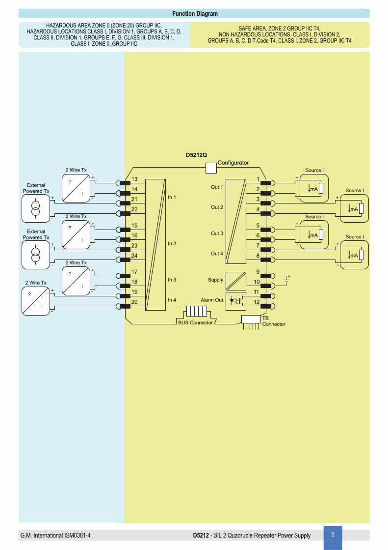
Function Diagram
SAFE AREA, ZONE 2 GROUP IIC T4, NON HAZARDOUS LOCATIONS, CLASS I, DIVISION 2,
GROUPS A, B, C, D T-Code T4, CLASS I, ZONE 2, GROUP IIC T4
HAZARDOUS AREA ZONE 0 (ZONE 20) GROUP IIC, HAZARDOUS LOCATIONS CLASS I, DIVISION 1, GROUPS A, B, C, D,
CLASS II, DIVISION 1, GROUPS E, F, G, CLASS III, DIVISION 1, CLASS I, ZONE 0, GROUP IIC
TBConnectorBUS Connector
21
D5212Q
Supply
Out 114
15
23
17
1
2
3
4
5
6
7
8
9
10
11
12
Configurator
Out 2
+
Alarm Out
13
22
16
24
19
18
20
+
-
ExternalPowered Tx
2 Wire Tx
?
I
+
-
+
-
ExternalPowered Tx
2 Wire Tx
?
I
+
-
2 Wire Tx
?
I
+
-
2 Wire Tx
?
I
+
-
Out 3
Out 4
In 1
In 2
In 3
In 4
mA
Source I
+
-
mA
Source I
+
-
mA
Source I
+
-
mA
Source I
+
-

D5212 - SIL 2 Quadruple Repeater Power Supply G.M. International ISM0361-4 6
D5212 series is isolated Intrinsically Safe Associated Apparatus installed into standard EN/IEC60715 TH 35 DIN-Rail located in Safe Area or Zone 2, Group IIC, Temperature T4 Hazard-ous Area (according to EN/IEC60079-15) within the specified operating temperature limits Tamb -40 to +70 °C, and connected to equipment with a maximum limit for power supply Um of 250 Vrms or Vdc. Not to be connected to control equipment that uses or generates more than 250 Vrms or Vdc with respect to earth ground. D5212 series must be installed, operated and maintained only by qualified personnel, in accordance to the relevant national/international installation standards (e.g. EN/IEC60079-14 Electrical apparatus for explosive gas atmospheres - Part 14: Electrical installations in hazardous areas (other than mines)), following the established installation rules, particular care shall be given to segregation and clear identification of I.S. conductors from non I.S. ones. De-energize power source (turn off power supply voltage) before plug or unplug the terminal blocks when installed in Hazardous Area unless area is known to be nonhazardous. Warning: substitution of components may impair Intrinsic Safety and suitability for Zone 2. Explosion Hazard: to prevent ignition of flammable or combustible atmospheres, disconnect power before servicing unless area is known to be nonhazardous. Failure to properly installation or use of the equipment may risk to damage the unit or severe personal injury. The unit cannot be repaired by the end user and must be returned to the manufacturer or his authorized representative. Any unauthorized modification must be avoided.
Warning
Operation
The quadruple channel Repeater Power Supply D5212Q provides a fully floating DC supply for energizing conventional 2-wire 0/4-20 mA transmitters located in Hazardous Area, and repeats the current in Safe Area to drive a load in applications requiring SIL 2 (according to IEC 61508:2010) in safety related systems for high risk industries. 4 channels I.S. analog input for 2-wire loop powered transmitters (or separately powered inputs, only for channels 1 and 2), providing isolation between input, output and supply, and current source output signals. The module is fully configurable to achieve any desired input/output combination: any number of outputs can be independently linked to each input. Output function can be configured as: adder, subtractor, low/high selector. An optically coupled open-drain alarm output with user-settable trip point is also provided. Modbus RTU RS-485 output is available on Bus connector to interface digital device. Presence of supply power is displayed by a “POWER ON” green signaling LED; fault for each channel and alarm conditions are signaled by related red front panel LED.
Installation
D5212 series is a quadruple repeater power supply housed in a plastic enclosure suitable for installation on EN/IEC60715 TH 35 DIN-Rail, with or without Power Bus or on customized Termination Board. D5212 series can be mounted with any orientation over the entire ambient temperature range. Electrical connections are accommodated by polarized plug-in removable screw terminal blocks which can be plugged in/out into a powered unit without suffering or causing any damage (for Zone 2 installations check the area to be nonhazardous before servicing). Connect only one individual conductor per each clamping point, use conductors up to 2.5 mm² (13 AWG) and a torque value of 0.5-0.6 Nm. The wiring cables have to be proportionate in base to the current and the length of the cable. On the section “Function Diagram” and enclosure side a block diagram identifies all connections. Identify the function and location of each connection terminal using the wiring diagram on the corresponding section, as an example: Connect 24 Vdc power supply positive at terminal “9” and negative at terminal “10”. Connect positive output of analog channel 1 (mA source mode) at terminal “1” and negative output (common to all channels) at “2” (channel 1). For other channels connect terminals “3” and “4” for channel 2, terminals “5” and “6” for channel 3, “7” and “8” for channel 4. Connect alarm output at terminals “11” and “12”. In case of a 2 wire input transmitter, connect the wires at terminal “13” for positive and “14” for negative (channel 1), or “15” for positive and “16” for negative (channel 2), or “17” for positive and “18” for negative (channel 3), or “19” for positive and “20” for negative (channel 4). Note that positive terminals of all channels are in common. For separately powered transmitters, connect input signal at terminal “21” for positive and “22” for negative (channel 1), or “23” for positive and “24” for negative (channel 2). Note that negative terminals of all channels are in common. Intrinsically Safe conductors must be identified and segregated from non I.S. and wired in accordance to the relevant national/international installation standards (e.g. EN/IEC60079-14 Electrical apparatus for explosive gas atmospheres - Part 14: Electrical installations in hazardous areas (other than mines)), make sure that conductors are well isolated from each other and do not produce any unintentional connection. Isolation in accordance with EN/IEC 60079-11 clause 6.3.13 is not provided between separate intrinsically safe circuits. Isolation in accordance with EN/IEC 60079-11 clause 6.3.13 is provided between non-intrinsically safe circuits and intrinsically safe circuits. Connect alarm transistors checking the load rating to be within the maximum rating (100 mA at 60 V (≤ 1.0 V voltage drop)). The enclosure provides, according to EN60529, an IP20 minimum degree of protection (or similar to NEMA Standard 250 type 1). The equipment shall only be used in an area of at least pollution degree 2, as defined in EN/IEC 60664-1. When installed in Zone 2, the unit shall be installed in an enclosure that provides a minimum ingress protection of IP54 in accordance with EN/IEC 60079-0. When installed in a Class I, Zone 2 Hazardous Location, the unit shall be mounted in a supplemental AEx or Ex enclosure that provides a degree of protection not less than IP54 in accordance with UL/CSA 60079-0. When installed in a Class I, Division 2 Hazardous Location, the unit shall be mounted in a supplemental enclosure that provides a degree of protection not less than IP54. The enclosure must have a door or cover accessible only by the use of a tool. The end user is responsible to ensure that the operating temperature of the module is not exceeded in the end use application. Units must be protected against dirt, dust, extreme mechanical (e.g. vibration, impact and shock) and thermal stress, and casual contacts. If enclosure needs to be cleaned use only a cloth lightly moistened by a mixture of detergent in water. Electrostatic Hazard: to avoid electrostatic hazard, the enclosure of D5212 series must be cleaned only with a damp or antistatic cloth. Any penetration of cleaning liquid must be avoided to prevent damage to the unit. Any unauthorized card modification must be avoided. D5212 series must be connected to SELV or PELV supplies. All circuits connected to D5212 series must comply with the overvoltage category II (or better) according to EN/IEC60664-1.
Start-up Before powering the unit check that all wires are properly connected, particularly supply conductors and their polarity, input and output wires, also check that Intrinsically Safe conductors and cable trays are segregated (no direct contacts with other non I.S. conductors) and identified either by color coding, preferably blue, or by marking. Check conductors for exposed wires that could touch each other causing dangerous unwanted shorts. Turn on power, the “power on” green led must be lit, for 2 wire transmitter connection the supply voltage on each channel must be ≥ 14 V, output signal should be corresponding to the input from the transmitter, alarm LED should reflect the input variable condition with respect to trip points setting. If possible change the transmitter output and check the corresponding Safe Area output.
G.M. International ISM0361-4 D5212 - SIL 2 Quadruple Repeater Power Supply 7
Configuration parameters: Screenshots:
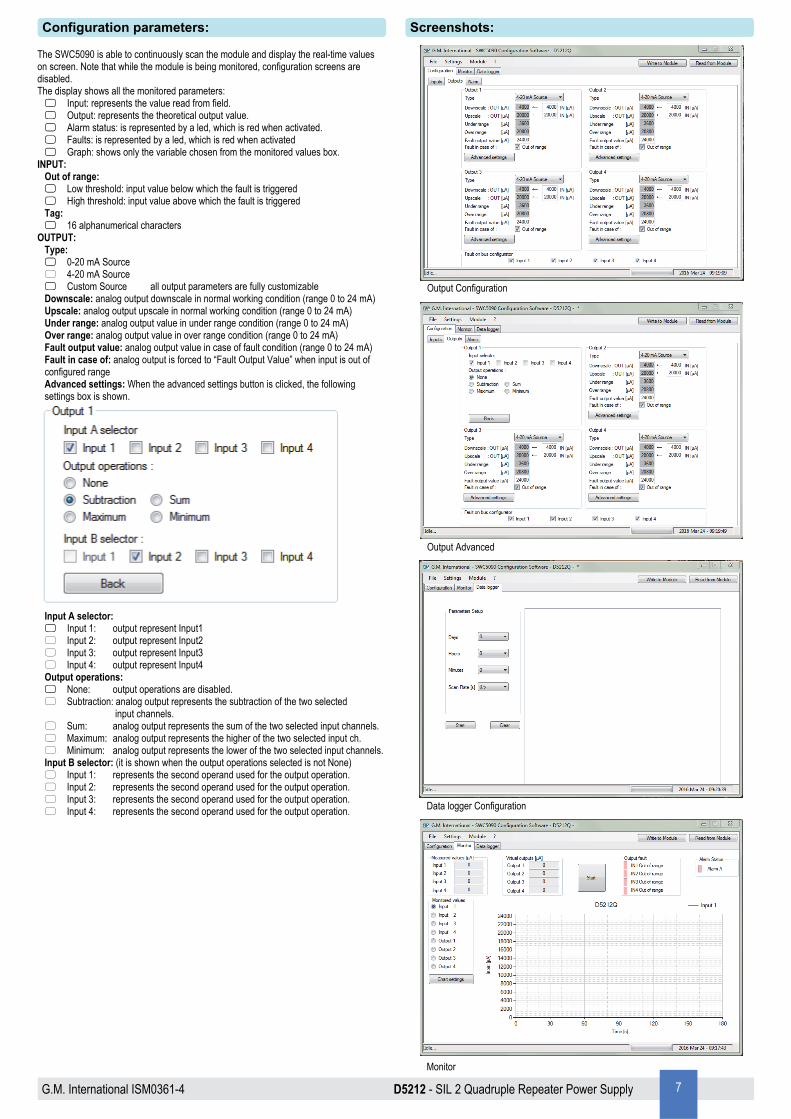
The SWC5090 is able to continuously scan the module and display the real-time values on screen. Note that while the module is being monitored, configuration screens are disabled. The display shows all the monitored parameters: Input: represents the value read from field. Output: represents the theoretical output value. Alarm status: is represented by a led, which is red when activated. Faults: is represented by a led, which is red when activated Graph: shows only the variable chosen from the monitored values box. INPUT: Out of range: Low threshold: input value below which the fault is triggered High threshold: input value above which the fault is triggered
Tag: 16 alphanumerical characters
OUTPUT: Type: 0-20 mA Source 4-20 mA Source Custom Source all output parameters are fully customizable Downscale: analog output downscale in normal working condition (range 0 to 24 mA)
Upscale: analog output upscale in normal working condition (range 0 to 24 mA) Under range: analog output value in under range condition (range 0 to 24 mA) Over range: analog output value in over range condition (range 0 to 24 mA) Fault output value: analog output value in case of fault condition (range 0 to 24 mA) Fault in case of: analog output is forced to “Fault Output Value” when input is out of configured range Advanced settings: When the advanced settings button is clicked, the following settings box is shown.
Input A selector: Input 1: output represent Input1 Input 2: output represent Input2 Input 3: output represent Input3 Input 4: output represent Input4 Output operations: None: output operations are disabled. Subtraction: analog output represents the subtraction of the two selected
input channels. Sum: analog output represents the sum of the two selected input channels. Maximum: analog output represents the higher of the two selected input ch. Minimum: analog output represents the lower of the two selected input channels. Input B selector: (it is shown when the output operations selected is not None) Input 1: represents the second operand used for the output operation. Input 2: represents the second operand used for the output operation. Input 3: represents the second operand used for the output operation. Input 4: represents the second operand used for the output operation.
Monitor
Data logger Configuration
Output Configuration
Output Advanced

D5212 - SIL 2 Quadruple Repeater Power Supply G.M. International ISM0361-4 8
Configuration parameters: Screenshots:
ALARM: Type: None: alarm is disabled Low: alarm is triggered when input descends below “Low Set” High: alarm is triggered when input ascends above “High Set” Window: alarm is triggered below “Low Set” and above “High Set” Alarm lock: alarm is inhibited until source ascends above or descends below the configuration
parameters, and then, it behaves as standard configuration. Input A selector: Input 1: alarm is triggered on Input1 Input 2: alarm is triggered on Input2 Input 3: alarm is triggered on Input3 Input 4: alarm is triggered on Input4 Output operations: None: output operations are disabled. Subtraction:analog output represents the subtraction of the two selected input ch. Sum: analog output represents the sum of the two selected input channels. Maximum: analog output represents the higher of the two selected input channels Minimum: analog output represents the lower of the two selected input channels Input B selector: (it is shown when the output operations selected is not None) Input 1: represents the second operand used for the output operation Input 2: represents the second operand used for the output operation Input 3: represents the second operand used for the output operation Input 4: represents the second operand used for the output operation NO contact position in alarm: Open: alarm output is closed under regular working conditions,
and it opens in case of alarm Closed: alarm output is open under regular working conditions, and it closes
in case of alarm Low Set: input value below which the alarm is triggered (in Low, Window) Low Hysteresis: hysteresis on the low set value High Set: Input value above which the alarm is triggered High Hysteresis: hysteresis on the high set value On Delay: time for which the input has to be in alarm condition before the alarm output is triggered,
configurable from 0 to 1000 seconds in steps of 100 ms Off Delay: time for which the input has to be in normal condition before the alarm output is
deactivated, configurable from 0 to 1000 seconds in steps of 100 ms. FAULT: alarm is triggered when input is out of configured range In case of fault: Ignore: alarm is not affected Lock status: remains in the same status as it was before fault occurred Alarm active: alarm is triggered Alarm inactive: alarm is deactivated
Alarm Configuration
Input Configuration

G.M. International ISM0361-4 D5212 - SIL 2 Quadruple Repeater Power Supply 9
Param. Description Notes Type (11) 0 G.M. Factory Code
Identification Data R
1 Instrument Code 2 Option Code 3 Hardware Release 4 Software Release
5 to 15 Reserved 16 Modbus Address
Communication Data R/W 17 Modbus Baudrate
18 Modbus Format 64 Input1 measured value(Low 16 bits) (1)
Input (Field) Data R
65 Input1 measured value(High 16 bits) (1)
66 Input2 measured value(Low 16 bits) (1)
67 Input2 measured value(High 16 bits) (1)
68 Input3 measured value(Low 16 bits) (1)
69 Input3 measured value(High 16 bits) (1)
70 Input4 measured value(Low 16 bits) (1)
71 Input4 measured value(High 16 bits) (1)
72 Input1 fault (2)
73 Input2 fault (2)
74 Input3 fault (2)
75 Input4 fault (2)
102 Input1 Downscale (Low 16 bits) (1)
Input (Field) Configuration R/W
103 Input1 Downscale (High 16 bits) (1)
104 Input1 Upscale (Low 16 bits) (1)
105 Input1 Upscale (High 16 bits) (1)
106 Input1 Fault Switch (3)
107 Input1 Low Range Fault (Low 16 bits) (1)
108 Input1 Low Range Fault (High 16 bits) (1)
109 Input1 High Range Fault (Low 16 bits) (1)
110 Input1 High Range Fault (High 16 bits) (1)
111 Input2 Downscale (Low 16 bits) (1)
112 Input2 Downscale (High 16 bits) (1)
113 Input2 Upscale (Low 16 bits) (1)
114 Input2 Upscale (High 16 bits) (1)
115 Input2 Fault Switch (3)
116 Input2 Low Range Fault (Low 16 bits) (1)
117 Input2 Low Range Fault (High 16 bits) (1)
118 Input2 High Range Fault (Low 16 bits) (1)
119 Input2 High Range Fault (High 16 bits) (1)
120 Input3 Downscale (Low 16 bits) (1)
121 Input3 Downscale (High 16 bits) (1)
122 Input3 Upscale (Low 16 bits) (1)
123 Input3 Upscale (High 16 bits) (1)
124 Input3 Fault Switch (3)
125 Input3 Low Range Fault (Low 16 bits) (1)
126 Input3 Low Range Fault (High 16 bits) (1)
127 Input3 High Range Fault (Low 16 bits) (1)
128 Input3 High Range Fault (High 16 bits) (1)
129 Input4 Downscale (Low 16 bits) (1)
130 Input4 Downscale (High 16 bits) (1)
131 Input4 Upscale (Low 16 bits) (1)
132 Input4 Upscale (High 16 bits) (1)
133 Input4 Fault Switch (3)
134 Input4 Low Range Fault (Low 16 bits) (1)
135 Input4 Low Range Fault (High 16 bits) (1)
136 Input4 High Range Fault (Low 16 bits) (1)
137 Input4 High Range Fault (High 16 bits) (1)
160 Output1 Downscale (Low 16 bits) (1)
Output Configuration R/W
161 Output1 Downscale (High 16 bits) (1)
162 Output1 Upscale (Low 16 bits)(1)
163 Output1 Upscale (High 16 bits)(1)
164 Output1 Under Range (Low 16 bits)(1)
165 Output1 Under Range (High 16 bits)(1)
166 Output1 Over Range (Low 16 bits)(1)
167 Output1 Over Range (High 16 bits)(1)
168 Output1 Fault Current (Low 16 bits)(1)
169 Output1 Fault Current (High 16 bits)(1)
170 Output1 Fault Mask(3)
172 Output1 InputA Selector(4)
173 Output1 InputB Selector(4)
174 Output1 Operation(5)
175 Output2 Downscale (Low 16 bits)(1)
176 Output2 Downscale (High 16 bits)(1)
177 Output2 Upscale (Low 16 bits)(1)
178 Output2 Upscale (High 16 bits)(1)
179 Output2 Under Range (Low 16 bits)(1)
180 Output2 Under Range (High 16 bits)(1)
181 Output2 Over Range (Low 16 bits)(1)
182 Output2 Over Range (High 16 bits)(1)
183 Output2 Fault Current (Low 16 bits)(1)
184 Output2 Fault Current (High 16 bits)(1)
185 Output2 Fault Mask(3)
187 Output2 InputA Selector(4)
188 Output2 InputB Selector (4)
189 Output2 Operation (5)
190 Output3 Downscale (Low 16 bits) (1)
191 Output3 Downscale (High 16 bits) (1)
192 Output3 Upscale (Low 16 bits) (1)
193 Output3 Upscale (High 16 bits) (1)
Supported ModBus Parameters: ModBus parameters details:
Supported ModBus Baudrates Index Baudrate
0 4800 1 9600 2 19200 3 38400 4 57600
Address 18: Supported Modbus Formats High Byte Low Byte
Bit position 15 14 13 12 11 10 9 8 7 6 5 4 3 2 1 0
Termination resistance (1 = enabled) Endianness 32 bit Data (0 = Little; 1 = Big)
Supported Modbus Parity: 0 8 data bit, no parity, 1 stop bit 1 8 data bit, even parity, 1 stop bit 2 8 data bit, odd parity, 1 stop bit

D5212 - SIL 2 Quadruple Repeater Power Supply G.M. International ISM0361-4 10
Param. Description Notes Type (11)
Output Configuration R/W
194 Output3 Under Range (Low 16 bits) (1)
195 Output3 Under Range (High 16 bits) (1)
196 Output3 Over Range (Low 16 bits) (1)
197 Output3 Over Range (High 16 bits) (1)
198 Output3 Fault Current (Low 16 bits) (1)
199 Output3 Fault Current (High 16 bits) (1)
200 Output3 Fault Mask (3)
202 Output3 InputA Selector (4)
203 Output3 InputB Selector (4)
204 Output3 Operation (5)
205 Output4 Downscale (Low 16 bits) (1)
206 Output4 Downscale (High 16 bits) (1)
207 Output4 Upscale (Low 16 bits) (1)
208 Output4 Upscale (High 16 bits) (1)
209 Output4 Under Range (Low 16 bits) (1)
210 Output4 Under Range (High 16 bits) (1)
211 Output4 Over Range (Low 16 bits) (1)
212 Output4 Over Range (High 16 bits) (1)
213 Output4 Fault Current (Low 16 bits) (1)
214 Output4 Fault Current (High 16 bits) (1)
215 Output4 Fault Mask (3)
217 Output4 InputA Selector (4)
218 Output4 InputB Selector (4)
219 Output4 Operation (5)
220 Fault Bus Configuration (4) Fault Config. R/W 240 Alarm Configuration (6)
Alarm Control R/W
242 Alarm Startup Lock (7)
243 Alarm Fault Configuration (8)
244 Alarm Fault Mask (3)
245 Contact Position in Case of Alarm (9)
246 Delay to Alarm Issue (10)
247 Delay to Alarm Removal (10)
248 Alarm Low Threshold (Low 16 bits) (1)
249 Alarm Low Threshold (High 16 bits) (1)
250 Alarm Low Threshold Hysteresis (Low 16 bits) (1)
251 Alarm Low Threshold Hysteresis (High 16 bits) (1) 252 Alarm High Threshold (Low 16 bits) (1)
253 Alarm High Threshold (High 16 bits) (1)
254 Alarm High Threshold Hysteresis (Low 16 bits) (1)
255 Alarm High Threshold Hysteresis (High 16 bits) (1) 256 Alarm InputA Selector (4)
257 Alarm InputB Selector (4)
258 Alarm Operation Selector (5)
464 EEPROM Write Command W 548 Output 1 virtual value (Low 16 bits) (1) Output Data R 549 Output 1 virtual value (High 16 bits) (1) Output Data R 553 Output 2 virtual value (Low 16 bits) (1) Output Data R 554 Output 2 virtual value (High 16 bits) (1) Output Data R 558 Output 3 virtual value (Low 16 bits) (1) Output Data R 559 Output 3 virtual value (High 16 bits) (1) Output Data R 563 Output 4 virtual value (Low 16 bits) (1) Output Data R 564 Output 4 virtual value (High 16 bits) (1) Output Data R 567 Alarm status (7) Alarm Data R 600 Ch. 1 chars 0, 1 Tags R/W 601 Ch. 1 chars 2, 3 Tags R/W 602 Ch. 1 chars 4, 5 Tags R/W 603 Ch. 1 chars 6, 7 Tags R/W 604 Ch. 1 chars 8, 9 Tags R/W 605 Ch. 1 chars 10, 11 Tags R/W 606 Ch. 1 chars 12, 13 Tags R/W 607 Ch. 1 chars 14, 15 Tags R/W 608 Ch. 2 chars 0, 1 Tags R/W 609 Ch. 2 chars 2, 3 Tags R/W 610 Ch. 2 chars 4, 5 Tags R/W 611 Ch. 2 chars 6, 7 Tags R/W 612 Ch. 2 chars 8, 9 Tags R/W 613 Ch. 2 chars 10, 11 Tags R/W 614 Ch. 2 chars 12, 13 Tags R/W 615 Ch. 2 chars 14, 15 Tags R/W 616 Ch. 3 chars 0, 1 Tags R/W 617 Ch. 3 chars 2, 3 Tags R/W 618 Ch. 3 chars 4, 5 Tags R/W 619 Ch. 3 chars 6, 7 Tags R/W 620 Ch. 3 chars 8, 9 Tags R/W 621 Ch. 3 chars 10, 11 Tags R/W 622 Ch. 3 chars 12, 13 Tags R/W 623 Ch. 3 chars 14, 15 Tags R/W 624 Ch. 4 chars 0, 1 Tags R/W 625 Ch. 4 chars 2, 3 Tags R/W 626 Ch. 4 chars 4, 5 Tags R/W 627 Ch. 4 chars 6, 7 Tags R/W 628 Ch. 4 chars 8, 9 Tags R/W 629 Ch. 4 chars 10, 11 Tags R/W 630 Ch. 4 chars 12, 13 Tags R/W 631 Ch. 4 chars 14, 15 Tags R/W
Supported ModBus Parameters: ModBus parameters details:
Notes: (1) Expressed in 100 nA (2) 0 = No fault,
1 = Input out of range (3) 0 = Ignore input fault,
1 = Report input out of range (4) 0 = Input1,
1 = Input2, 2 = Input3, 3 = Input4
(5) 0 = None, 1 = Sum, 2 = Subtraction, 3 = Maximum, 4 = Minimum
(6) 0 = None, 1 = Low, 2 = High, 3 = Window, 4 = Fault repeater
(7) 0 = Inactive, 1 = Active
(8) 0 = Ignore, 1 = Lock status, 2 = Alarm active, 3 = Alarm inactive
(9) 0 = Open, 1 = Closed
(10) Expressed in tenths of seconds (11) Parameter type:
R = read only, W = write only, R/W = read and write
1 Save Input/Output Configuration 2 Save Modbus configuration 8 Save Tags
Address 464: EEPROM Write High Byte Low Byte
Bit position 15 14 13 12 11 10 9 8 7 6 5 4 3 2 1 0