simplifying prc-026 compliance with practical solutions
TRANSCRIPT

Simplifying PRC-026 Compliance With Practical Solutions You Least Expect
Pratheek Annamdevula, Austin Thurman, Michael Thompson, Brian Smyth, and Demetrios Tziouvaras
Schweitzer Engineering Laboratories, Inc.
Presented at the 74th Annual Georgia Tech Protective Relaying Conference
Virtual Format April 28–30, 2021
Previously presented at the 74th Annual Conference for Protective Relay Engineers, March 2021
Originally presented at the 46th Annual Western Protective Relay Conference, October 2019

1
Simplifying PRC-026 Compliance With Practical Solutions You Least Expect
Pratheek Annamdevula, Austin Thurman, Michael Thompson, Brian Smyth, and Demetrios Tziouvaras, Schweitzer Engineering Laboratories, Inc.
Abstract—NERC Standard PRC-026-1 requires protection systems on the bulk electric system (BES) to not trip for stable power swings. For impedance (21) relays, the standard defines an unstable power swing region on the impedance plane. Any distance element tripping characteristic that is not contained within this defined unstable power swing region and trips in less than 15 cycles requires mitigation.
While completing PRC-026-1 compliance evaluations for many lines and generators with relays of different makes and models, the authors found that, in most cases, impedance relays on generators are compliant. However, impedance relays on transmission lines are a different story. Many owners of noncompliant line protection systems are contemplating expensive solutions such as replacing relays, adding digital channels to convert from 21 to 87 (differential) protection, or performing extensive power swing studies to justify modifying the highly conservative PRC-026-1 unstable power swing region.
Many of these solutions, such as converting to 87 or supervising 21 elements with power swing blocking (PSB) without also enabling out-of-step tripping (OST), can actually reduce the reliability of the BES. They do so by preventing the separation of two parts of the system that have gone out of step (i.e., swing angle goes through 180 degrees) from the inherent tripping of impedance elements near the electrical center between the out-of-step regions of the power system.
This paper offers practical corrective action plans (CAPs) that can provide compliance in nearly all cases without replacing the relays or preventing trips for true out-of-step power swings. This paper discusses various types of PSB and OST schemes, and other features available in multifunction line relays, that can help with compliance. Many of the CAPs presented are not the solutions you expect.
I. INTRODUCTION Following the August 14, 2003 Northeast blackout, the
Federal Energy Regulatory Commission (FERC) directed the North American Electric Reliability Corporation (NERC) “to develop a Reliability Standard that requires the use of protective relay systems that can differentiate between faults and stable power swings” [1]. In response to the FERC directive, NERC initiated Project 2010-13.3 Phase 3 of Relay Loadability: Stable Power Swings and raised a request for research from the System Protection and Control Subcommittee (SPCS) to support the project. In response to this request, SPCS submitted a report in August 2013 concluding that a Reliability Standard to address the performance of protective relays during stable swings is unnecessary. However, SPCS offered to provide recommendations for applicability and requirements that the NERC Standards Committee could use if NERC chose to develop a Reliability Standard. The result of this effort was the PRC-026-1 standard.
The purpose of PRC-026-1 is “to ensure that load-responsive protective relays are expected to not trip in response to stable power swings during non-fault conditions” [2]. As per the requirements of PRC-026-1, each planning coordinator will determine which bulk electric system (BES) elements are susceptible to power swings and notify the applicable generator or transmission entities. Once notified, the entities must evaluate the applicable BES elements for PRC-026-1 compliance and, if required, modify the protection system for any non-compliant cases.
While evaluating PRC-026-1 compliance of several transmission lines, the authors found that overreaching Zone 2 pilot and/or step Zone 1 distance elements tend to fail PRC-026-1 compliance requirements.
The authors realized that implementing blinder-and-timer-based solutions such as the dual-blinder power swing blocking (PSB) scheme is not always feasible to meet PRC-026-1 compliance. Most of the non-compliant lines had large impedance zones that greatly reduced the area between the impedance zones and PRC-023-4 load point to set the PSB blinders with adequate margin. Secondly, it is impossible to implement an out-of-step tripping (OST) function using the dual-blinder scheme and meet PRC-026-1 compliance because the inner blinder needs to be outside the largest impedance zone while being inside the unstable power swing region defined in PRC-026-1.
In response to PRC-026-1 and limitations of blinder-and-timer-based solutions to meet compliance, many transmission entities are investing in costly solutions such as replacing relays, adding digital channels to convert from distance to current differential, or performing extensive and expensive power swing studies to justify modifying the highly conservative PRC-026-1 unstable power swing region characteristic to allow their impedance relays to meet compliance. The criteria used to construct the PRC-026-1 unstable power swing region lean toward security to stable power swings even under extreme system conditions. This results in a PRC-026-1 unstable power swing region that is closer to the protective impedance element characteristics.
This paper begins by detailing the PRC-026-1 requirements and criteria. The paper outlines the power swing detection elements commonly available in multifunction line relays. Further, it discusses the effects of applying dual-blinder schemes as PRC-026-1 mitigation solutions on BES reliability. The paper concludes by providing readers with simple, economical, and practical mitigation solutions that use native functions available in most in-service multifunction relays

2
without compromising dependable system protection and BES reliability. We encourage readers to refer to the appendix to understand how the relays are affected and why their operation should be supervised during power swings.
While PRC-026-1 covers both phase-distance and phase-overcurrent protective relays, this paper will concentrate on compliance of phase distance protection as it is the most prevalent type of protection used on the BES. Secondly, the scope of this paper is limited to two terminal transmission lines. Reference [3] provides guidance on evaluating three-terminal lines for PRC-026-1 compliance.
II. PRC-026-1 GUIDELINES
A. PRC-026-1 Requirements PRC-026-1 consists of four stages of requirements and
measures [2]. See Fig. 1. In the first stage, each planning coordinator shall identify, at least once every calendar year, the BES elements under their jurisdiction on which protective relays are most likely to be challenged by power swings. They are to notify the owners of the applicable BES elements. In the second stage, within twelve calendar months of being notified, the transmission and generation owners must determine whether the load-responsive protective relays meet PRC-026-1 Attachment B criteria. The second stage includes an additional requirement stating that within twelve calendar months of becoming aware that a BES element tripped in response to a stable or unstable power swing, the generator and transmission owner must determine whether the load-responsive relays meet PRC-026-1 Attachment B criteria. In the third stage, each generation and transmission owner must develop a corrective action plan (CAP) within six calendar months of determining which load-responsive relays failed to meet the PRC-026-1 Attachment B criteria. The PRC-026-1 mitigation solutions proposed in the CAP should either make the protection system meet PRC-026-1 Attachment B criteria or exclude the protection system under PRC-026-1 Attachment A criteria. The fourth and final stage requires generation and transmission owners to implement the solutions proposed in the CAP and update it when actions or timetables change.
Fig. 1. PRC-026-1 requirements.
B. PRC-026-1 Attachment A and Attachment B Criteria Two attachments are included with this standard.
Attachment A details the applicable relay elements that require evaluation per PRC-026-1, while Attachment B details the requirements to meet compliance. Attachment B is split into two criteria; Criterion A details the compliance requirements of
impedance-based elements and Criterion B details the compliance requirements of overcurrent-based elements.
1) Attachment A Criteria Per Attachment A, this standard applies to load-responsive
protective relay elements that can trip a breaker within 15 cycles. Elements that are considered load responsive include, but are not limited to, phase-distance, phase-overcurrent, out-of-step, and loss-of-field elements. There are exemptions listed in Attachment A that include elements that operate under contingency conditions such as switch-onto-fault (SOTF), generator reverse power, loss-of-potential (LOP) elements, or current differential relays. It should also be noted that elements supervised by a PSB function are excluded from this standard.
2) Attachment B Criteria Impedance elements are widely used in transmission line
protection and are the focus of this paper; therefore, Attachment B Criterion A will be our focal point. Per Criterion A, an R-X plane is used to evaluate compliance for impedance-based elements by designating an unstable power swing region. Criterion A states that an impedance-based protective relay element will not trip for a stable power swing if its characteristic is completely contained within the unstable power swing region defined in PRC-026-1. Tripping on impedance outside of this unstable power swing region is prohibited. However, tripping for power swings that traverse into the unstable power swing region is acceptable.
Fig. 2 describes a two-machine model where the power system around a transmission line of interest is reduced to a two-machine equivalent, the line of interest, and a parallel transfer impedance branch. PRC-026-1 requires us to assume that all parallel network paths in the system are open as shown in Fig. 2. The PRC-026-1 unstable power swing region is an impedance characteristic that the swing traces on the impedance plane when the sources of the two-machine equivalent model freely slip against each other under the system conditions described. The PRC-026-1 unstable power swing region is formed by the union of the following three shapes (see Fig. 3):
• Lower loss-of-synchronism circle: The characteristic that an impedance relay traces when the ratio of the sending- to receiving-end voltage is kept constant at 0.7 and the angle between the two machines is varied between 0–120 degrees.
• Upper loss-of-synchronism circle: The characteristic that an impedance relay traces when the ratio of the sending- to receiving-end voltage is kept constant at 1.43 and the angle between the two machines is varied between 0–120 degrees. Note that 1.43 is simply the inverse of 0.7.
• Lens characteristic: The characteristic that an impedance relay traces when the ratio of sending- to receiving-end voltage is varied from 0.7–1.43 and the angle between the two machines is held constant at 120 degrees.

3
Fig. 2. Two-machine equivalent model.
Fig. 3. PRC-026-1 unstable power swing region.
Combining these three characteristics results in a dumbbell-shaped characteristic that is used to evaluate all applicable impedance-based elements for compliance. The area within the dumbbell-shaped characteristic is the PRC-026-1 unstable power swing region. An impedance element is compliant if it is completely contained within the PRC-026-1 unstable power swing region. As an example, overreaching Zone 2 pilot and step Zone 1 in Fig. 3 are not compliant because they are not completely contained within the unstable power swing region.
NERC has described the technical basis behind the guidelines and system specifics considered in Attachment B Criterion A in the PRC-026-1 document [2]. Some of them are provided in the following sections.
a) Critical Clearing Angle for Stability Critical angle for maintaining stability as per PRC-026-1 is
120 degrees. Although theoretically a pole slip occurs only after the relative rotor angles go past 180 degrees, NERC suggests it is commonly accepted across the industry that when the angular difference between two machines reaches 120 degrees, the system is beyond recovery and it can be safely concluded that the systems will pull out of synchronism. PRC-026-1 also has a provision allowing owners to perform the evaluation with a critical angle less than 120 degrees provided they have a documented transient stability analysis that supports the angle used. A critical angle less than 120 degrees will result in a PRC-026-1 unstable power swing region that is larger, thus increasing the chances of achieving compliance.
b) System and Parallel Transfer Impedances The PRC-026-1 unstable power swing region on the R-X
plane depends upon the total system impedance (sending-end source impedance, line impedance, and receiving-end source impedance). Attachment B Criterion A states that the transfer impedance in parallel with the line being evaluated between the two sources should be removed when constructing the PRC-026-1 unstable power swing region. Removing the parallel transfer impedance results in the worst possible contingency case (where all other lines are out), thus removing the infeed effect. This will naturally result in a more restrictive PRC-026-1 unstable power swing region characteristic bringing it closer to the distance element characteristic. If the parallel transfer impedance is considered, there is current division through that branch. Hence, the relay sees a lesser current and a higher system impedance. This makes it more likely for the impedance characteristics to be contained within the PRC-026-1 unstable power swing region, thus the characteristics now appear compliant with PRC-026-1. However, it is likely that a swing or stressed system condition may be caused by adjacent lines out of service or tripped due to system conditions. The boundary between a stable and unstable swing may shrink and expose the tripping element characteristic to possibly operate on stable swings.
c) Sending- and Receiving-End Voltages NERC chose 0.7 per unit internal generator voltage as the
lower limit to be more conservative than PRC-023-4 and PRC-025 limits [4] [5], which is 0.85 per unit. This will result in a smaller PRC-026-1 unstable power swing region and provides a more restrictive compliance boundary for impedance elements.
III. POWER SWING DETECTION ELEMENTS There are two fundamentally different protective functions
related to power swings; the PSB function and the OST function [6]. The PSB function discriminates faults from stable or unstable power swings. The PSB function can be used to block relay elements that are prone to operate during power swings to prevent system separation. In addition, most modern PSB functions include provisions to unblock previously blocked relay elements to allow them to operate for faults, in their zone of protection, that could occur during a power swing.
There are several methods used to detect power swings. Readers not familiar with the common power swing detection methods are strongly encouraged to refer to [6]. The following is a summary to get us started.
A. Power Swing Blocking Functions Power swings can be detected by measuring the rate-of-
change of impedance. In the past, due to the technological limitations, blinder-and-timer based methods were developed to measure this rate of change. The rate of change is measured in a relatively crude way by timing how long an impedance trajectory moves between two blinders. It is a one-shot operation rather than a continuous process. With the advent of digital relays, new methods such as the continuous rate of change of the swing-center voltage (SCV) method and the

4
continuous impedance rate-of-change (dZ/dt) measurement method have been introduced. We refer to these methods as continuous measurement power swing detection methods. Typically, these methods do not require any power swing detection element settings or transient stability analysis studies as required for the application of blinder-and-timer based methods.
Traffic speed control is presented here as an analogy to help understand the difference between blinder-and-timer-based and continuous measurement power swing detection methods. To determine the speed of a moving car before the advent of traffic radar guns, a speed trap was implemented by painting two lines on the pavement. A patrol officer would use a stopwatch to measure the time it took for a car to cross the two painted lines and then calculated its speed. The two painted lines had to be adequately spaced so the patrol officer could time the moving car accurately. This method required a designated area on the road and a stopwatch to determine the speed of a moving car. However, with traffic radar guns, patrol officers can directly measure the speed of a moving car using the Doppler effect. Patrol officers can measure the speed of a moving car on any road just by pointing a radar gun at the car.
1) Blinder-and-Timer-Based Power Swing Detection Methods
Like the example of two painted lines on pavement and a stopwatch, blinder-and-timer-based power swing detection methods like the dual-blinder PSB scheme place two blinders spaced adequately apart on an impedance plane and measure the time it takes for an impedance trajectory to cross the blinders (see Fig. 4) [6]. If the measured time is longer than the preset time, a PSB is declared and the relay is blocked from tripping. However, if the measured time is less than the preset time, the relay will consider that the system is experiencing a fault and allow the distance elements to operate.
Fig. 4. Dual-blinder scheme.
One limitation of the blinder-and-timer-based methods is that the power system parameters used to determine the settings are unlikely to reflect the actual system conditions at the time of the disturbance. In an interconnected power system, the source impedances vary constantly according to generation mix and network changes. Additionally, events involving external faults or extreme loading can put the apparent impedance between the blinders and fool the PSB logic, or the swing trajectory can move diagonally or vertically. When these events occur, there
is a possibility that blinder-and-timer-based methods might misoperate because they do not monitor the system continuously.
This paper uses the term blinder to describe these schemes. However, many schemes use closed inner and outer characteristics such as circles, lenses, tomatoes, or polygons. All work basically the same way so they are not discussed separately.
2) Continuous Measurement Methods Continuous measurement power swing detection methods
are a modern version of radar guns that directly determine whether the power system is experiencing a power swing either by continuously monitoring the rate-of-change of SCV or rate-of-change of apparent impedance. A major advantage of the continuous measurement power swing detection methods is that they do not require any user settings because they do not depend on system impedance or swing rates, unlike the blinder-and-timer-based methods.
Reference [7] describes a PSB method that uses the rate-of-change of the positive-sequence SCV to detect power swing conditions. The swing center of a two-source power system is the location where the voltage magnitude equals zero when the angle between the source voltages is 180 degrees.
Continuous impedance rate-of-change (dZ/dt) measurement methods monitor the trajectory of loop impedances in the complex plane. One particular implementation of this method monitors all six loop impedances and measures dZ/dt on a per-loop basis. This method declares a power swing on a per-loop basis when that loop’s impedance traverses the apparent impedance plane at a rate consistent with a power swing [8].
B. Out-of-Step Tripping Functions The OST function protects the power system during unstable
conditions. When two areas of the power system are no longer synchronized, the OST function initiates network separation to form islands. It is desirable that separation occurs such that a load-generation balance is achieved within each island. During an out-of-step condition, many relay systems are prone to operate and cause undesired tripping; therefore, PSB functions are used to prevent undesired operations and allow the OST functions to achieve controlled system separation to prevent bigger blackouts.
OST systems can be classified in two ways: • Trip-on-the-way-out (TOWO) systems: These systems
only initiate a trip after a pole slip has occurred by tracking the impedance trajectory and ensuring that it enters from one side of the R-X plane and exits the opposite side and are therefore relatively secure from tripping on a stable swing.
• Trip-on-the-way-in (TOWI) systems: These systems require characteristics like blinders so they can implement TOWI when a swing enters the inner characteristic. TOWI systems require careful analysis to not trip on a stable swing.
Note that a swing can enter from either the positive or the negative load region. Generally, most of the OST schemes are set to TOWO because it has a softer impact on the breakers and

5
minimizes breaker damage [6]. The power swing detection methods discussed previously can also be used for OST applications.
1) Blinder-and-Timer-Based Out-of-Step Detection Methods
These methods are based on the rate-of-change of apparent impedance measured when an impedance trajectory passes through two (or three) blinders. Like the dual-blinder PSB scheme discussed previously, the dual-blinder OST scheme places two adequately spaced blinders on an impedance plane and measures the time it takes for an impedance trajectory to cross the two blinders. However, the dual-blinder OST scheme has an OST timer (OSTD) in addition to a PSB timer (PSBD). Dual-blinder schemes that implement both PSB and OST are difficult to set. The inner blinder setting is critical because once the impedance enters the inner blinder, an OST is declared—even if the swing is stable. The scheme differentiates between a stable and unstable swing by the swing rate, which is nearly impossible to predict with confidence for any given disturbance even with extensive swing studies. This is one reason why the dual-blinder OST scheme is difficult to implement.
Fig. 5. Dual-blinder timer scheme.
The triple-blinder OST scheme works similarly to the dual-blinder OST scheme. However, the triple-blinder scheme has an additional middle blinder (see Fig. 6). The outer and middle
blinders are used to assert PSB. The inner blinder is used to assert OST. Unlike the dual-blinder OST scheme, where the settings for the inner blinder are critical and difficult to calculate, the settings for the triple-blinder OST scheme are relatively easy to calculate.
Fig. 6. Triple-blinder OST scheme.
Also similar to the dual-blinder OST scheme, the triple-blinder OST scheme has two timers that require configuration: a PSB timer and an OST timer. The PSB timer measures the time an impedance trajectory stays between the outer and middle blinders. The OST timer measures the time an impedance trajectory stays between the middle and inner blinders. The PSB timer starts when a swing enters the outer blinder. If the PSB timer expires before the trajectory reaches the middle blinder, the scheme will declare that the system is experiencing a power swing and assert PSB. The scheme will allow tripping only when the impedance trajectory reaches the inner blinder. The triple-blinder OST scheme can also perform TOWI and TOWO. This scheme is discussed further in Section VI.
2) Blinder-Based Out-of-Step Detection Methods Supervised by Continuous Measurement
The continuous measurement PSB methods discussed previously can also be used to implement OST functions. These methods may use blinders to track the impedance trajectory on the impedance plane. During an unstable power swing, the impedance trajectory travels from the positive resistance (+R) to the negative resistance (–R) region or vice versa. If the scheme tracks this impedance change, we can declare that the system is experiencing an unstable swing. If the scheme does not track this change, the impedance trajectory is a stable swing.
The rate of change of SCV PSB scheme uses blinders to perform the OST function by tracking the impedance trajectory. The OST function will be active only when the SCV PSB scheme detects power swings. The OST blinders associated with the rate-of-change of SCV power swing detection method require eight blinder settings [7]. While the eight blinders are grouped to form two quadrilateral zones, individual blinders are used in the OST logic. This is a subtle but significant distinction between this scheme and blinder-and-timer-based schemes.

6
When a swing trajectory passes through the OST blinders in the SCV PSB scheme, each individual blinder asserts or deasserts based on the trajectory location. For the sake of simplicity, we will only discuss the inner resistive blinders RR6 and RL6. See Fig. 7. Depending on the position of the trajectory, each individual inner resistive blinder is asserted or deasserted as shown in Table I.
TABLE I OST BLINDER ASSERTION AND DEASSERTION
Trajectory Position RR6 RL6
A 0 0
B 1 0
C 0 1
D 0 0
Fig. 7. Swing trajectory through OST blinders.
The scheme observes the assertion and deassertion patterns of the individual blinders and determines whether the swing trajectory moved from right-to-left or left-to-right on the impedance plane. Please note that this discussion is a simplified version of the actual scheme. In the actual scheme, all individual blinder elements work together to track the swing trajectory on the impedance plane. The main message is that by using individual blinders instead of polygons, the OST blinders associated with the SCV scheme can track the entry and exit points of a swing trajectory and take appropriate action.
Dual-blinder OST schemes also have similar resistive and reactive blinder settings as the OST blinders associated with the SCV PSB scheme. However, these settings are used to form a bounded polygon characteristic on the impedance plane as shown in Fig. 8. Each polygon characteristic has only one associated status output as shown in Fig. 8.
Consider the ZU trajectory given in Fig. 8. When the ZU trajectory enters the outer and inner polygon characteristics, word bits X7ABC and X6ABC assert, respectively, as shown in Table II. If the trajectory is an unstable swing, it will leave the inner and outer characteristic from the left side of the impedance plane as shown in Fig. 8; word bits X6ABC and X7ABC deassert. When set to TOWO, the relay will trip when the trajectory leaves the polygon characteristics. In other words, a TOWO trip is issued when X6ABC or X7ABC deasserts. The
dual-blinder OST TOWO scheme in some relays trips when the swing trajectory leaves the inner characteristic, and some other relays trip when the swing trajectory leaves the outer characteristic.
Fig. 8. Swing trajectory in a dual-blinder OST scheme.
TABLE II DUAL-BLINDER OST ASSERTION AND DEASSERTION
Swing Trajectory
Trajectory Position X6ABC X7ABC
ZU
AU 0 1
BU 1 1
CU 0 1
DU 0 0
ZS
AS 0 1
BS 1 1
CS 0 1
DS 0 0
Consider the ZS trajectory, which is a stable swing trajectory, given in Fig. 8. When ZS enters the outer characteristic, the OST scheme timers start. Assume the OST timer expired before the swing trajectory reached the inner characteristic. Once the swing reaches the inner characteristic, the relay will declare an OST condition. However, because ZS is a stable swing, it exits the inner and outer polygon characteristics from the same side that it entered. This is the same sequence of X6ABC and X7ABC assertion/deassertion that took place in the ZU trajectory example. See Table II. However, in the case of the ZS trajectory, the relay tripped on a stable swing condition. This is not desirable. The inner blinder resistive settings are critical for this reason. A stable swing trajectory should never cross or intersect the inner blinder.
Unlike the individual OST blinders in the SCV scheme, polygon characteristics cannot track the entry and exit points of an impedance trajectory. This is another reason why the OST blinders associated with the SCV scheme are superior to the blinder-and-timer-based OST schemes.

7
The triple-blinder OST scheme works similarly to the dual-blinder OST scheme. It also has three polygon characteristics that work exactly like the polygon characteristics in the dual-blinder OST scheme. The key advantage of the triple-blinder OST scheme is that the PSB and OST functions are decoupled to middle and inner characteristic, respectively. That allows us to place the inner characteristic close to the line impedance such that the inner characteristic power angle is around 140–160 degrees. If an impedance trajectory manages to reach the inner blinder, it is likely that the trajectory is an unstable swing and the relay can initiate a trip when the trajectory leaves the outer blinder.
IV. DESIRED RESPONSE OF RELAYS DURING POWER SWINGS The desired response during power swings is simple and
straightforward. If the power system is experiencing a stable swing, from which it can recover, relays should restrain operation. If the power system is experiencing an unstable swing, perform controlled tripping of the transmission line breakers, i.e., tripping the breakers when the two OOS systems are close to an in-phase condition. Initiate controlled system separation of the power systems that have lost synchronism to form islands with a load-generation balance.
While the requirements are simple, it is challenging to implement them in a large, interconnected power system. To accomplish a controlled system separation, we must perform extensive transient stability analysis covering many possible contingency conditions to determine optimal system separation points where a load-generation balance can be achieved. In situations where a healthy load-generation balance cannot be achieved, some form of load- or generation-shedding scheme should be in place to minimize the possibility of collapse in each of the separated systems. Similarly, the power swing trajectories during various system conditions should be simulated to identify optimal OST locations. The philosophy of optimal placement of OST systems or controlled system separation points is beyond the scope of PRC-026-1 standard and this paper.
As per PRC-026-1 Attachment A criteria, the protective relays that has its distance elements supervised by PSB, and current differential relays can be excluded from the requirements of the standard. This may provide an indirect motivation for the transmission entities to either enable PSB supervision only without enabling OST protection, or replace distance protection with current differential protection to be exempted from PRC-026-1 compliance. Complete removal of impedance-based protection may hurt the BES reliability by preventing separation of the power systems that have gone out-of-step in the common case where no engineered system separation scheme exists. The authors would like to draw the reader’s attention to some key conclusions from the SPCS report:
Operation of transmission line protection systems was not causal or contributory to six of the most significant system disturbances that have occurred since 1965. System separation
during several of these disturbances did occur due to unstable power swings, and it is likely that the scope of some events and potential for equipment damage would have been greater without dependable tripping on unstable swings to physically separate portions of the system that lost synchronism.
Given the relative risks associated with a lack of dependable operation for unstable power swings and the lack of secure operation for stable swings, it is generally preferable to emphasize dependability over security when it is not possible to ensure both for all possible system conditions. Prohibiting use of certain types of relays may have unintended negative outcomes for Bulk‐Power System reliability….
…exclusive use of current‐only‐based protection is not practical and would reduce dependability of tripping for system faults and unstable power swings. A power system with no remote backup protection is susceptible to uncleared faults and the inability to separate during unstable power swings during extreme system events. Although current‐only‐based protection is secure for stable power swings and can be used on lines which require tripping on out‐of‐step conditions, additional separate out‐of‐step protection is required. Application of impedance‐based backup protection and, where necessary, out‐of‐step protection, reintroduces the need to discriminate between stable and unstable power swings. [1]
The authors concur with the conclusions made by the SPCS report. Even though solutions like converting to current differential or PSB only supervision will make the relay systems get exempted from PRC-026-1 compliance, they also make the relays immune to unstable power swings. If a relay restrains operation during unstable power swings, the systems that have lost synchronism will continue to slip poles against each other, increasing the probability of a system blackout. We believe that having no separation at all during true OOS conditions is detrimental to the reliability of the power system. When PSB is applied in a system, some form of OST function should always be in place.
There can be situations where tripping due to unstable swings may result in the opening of critical transmission lines and further weaken the system when it is already under stressed conditions, leading to system collapse. In such cases, it may be in the best interest of the BES reliability to not allow tripping of these critical transmission lines and to modify the relay systems to be immune to power swings; however, allow the system to separate at different locations in response to unstable swing conditions. Remember, it is important that some form of OST always be in place when PSB is applied in a system. This

8
action is a form of controlled system separation where the system is separated at optimum points to maintain stability.
The key message is that while modifying the protection system to meet PRC-026-1 compliance, the transmission entities should avoid any consequences that may negatively impact the BES reliability. The goal of PRC standards is to improve the reliability of the power system, not just meet mandated requirements.
V. LIMITATIONS OF THE DUAL-BLINDER SCHEME AS A PRC-026-1 MITIGATION SOLUTION
When we began evaluating lines for PRC-026-1 compliance, we assumed we would simply enable the common dual-blinder PSB schemes to mitigate any noncompliant applications. We reviewed multiple lines with in-service transmission line relays from different manufacturers for PRC-026-1 compliance. There was a pattern of electrically long transmission lines with high load capabilities, failing PRC-026-1 compliance. Long transmission lines led to large impedance tripping zones. Predominately the large pilot zones were non-compliant, being previously set with only the load point defined by PRC-023-4 as a restriction. See Fig. 9 for an example of a non-compliant line.
Fig. 9. PRC-026-1 non-compliant distance zones.
The dual-blinder PSB scheme is built into most microprocessor relays and utilizes two blinders or polygons to detect a power swing. There is a limitation to keep in mind when setting a dual-blinder PSB scheme. The inner blinder must be located outside of applicable tripping zones to block any inherent tripping if the impedance during a power swing encroaches on the tripping element. Many interpret PRC-023-4, R2 as requiring the outer blinder be located inside the PRC-023-4 load point to prohibit blocking during load conditions. Another interpretation maintains it is permissible to set the outer PSB blinder to encroach on the PRC-023-4 load point if the PSB scheme has provision to limit the duration of PSB
should the line experience the stressed system load flow conditions specified in PRC-023-4. For this paper, we use the more conservative assumption that PRC-023-4, R2 requires the outer PSB blinder be set compliant with PRC-023-4.
As illustrated in Fig. 9, most of the non-compliant lines have large impedance zones that greatly reduce the area between the distance zones and PRC-023-4 load point to set the blinders with adequate margin. In some cases, the impedance zones encroach the PRC-023-4 load point. In this scenario, it is impossible to set blinders as there is no room.
Secondly, if there is no engineered system separation scheme in place, OST should be enabled whenever PSB is enabled. For the dual-blinder scheme to provide OST function, it is imperative that the inner blinder be set such that it is immune to stable power swing tripping. Per PRC-026-1 guidelines, the inner blinder should be set inside the PRC-026-1 unstable power swing region. See Fig. 10. However, the scheme would have to determine power swing conditions prior to the swing entering the impedance zones.
Fig. 10. Inner blinder limitations.
It is not possible to meet these conflicting criteria because the inner blinder would need to be set inside the PRC-026-1 unstable power swing region while remaining outside the tripping zones. The inner blinder cannot perform both OST and PSB functions without being at two different locations on the R-X plane.
We would like to bring the readers’ attention back to Fig. 9. This is a plot of a real line application that was evaluated for PRC-026-1 compliance. Readers should notice that the PRC-026-1 unstable power swing region is encroaching the PRC-023-4 load region. Obviously, the power system cannot be in a stable load flow state and an unstable power swing state simultaneously. We point out that PRC-023-4 and PRC-026-1 have different purposes. The PRC-023-4 load point represents an extreme loading condition that the load-responsive relays must not trip for. This load point has a large margin built in. It

9
is not meant to represent a realistic long-term operating state. The PRC-026-1 unstable power swing region is not meant to represent a realistic limit between stable and unstable power swings. The requirements stated in PRC-026-1 and PRC-023-4 can easily be in conflict.
Applying the dual-blinder scheme as a PRC-026-1 mitigation is not always feasible. We need to utilize other relay elements and develop practical PRC-026-1 mitigation solutions.
Reference [9] proposes an improvement to the dual-blinder scheme. The inner blinder can be used as a blinding element or to “cut off” the portion of the distance characteristic that is susceptible to stable power swing tripping, which in our case is the area of the distance characteristic that is not contained within the PRC-026-1 unstable power swing region. This scheme can be engineered to provide PSB, OST, and dependable fault detection; however, it requires custom logic. Because the goal of this paper is to simplify PRC-026-1 compliance, we will not consider this solution further.
VI. PRACTICAL PRC-026-1 SOLUTIONS The PRC-026-1 mitigation solutions that we implement
must meet two main objectives: • Meet PRC-026-1 compliance – Secure to stable power
swings. • Maintain dependable system protection – Dependable
tripping to true unstable swings and internal faults. PRC-026-1 prescribes how to obtain the unstable power
swing region characteristic in the R-X plane for assessing compliance. The network reduction function in commercially available short-circuit programs can be used to obtain the unstable power swing region characteristic. The method reduces the system around the line being assessed to a two-machine equivalent and assumes that all parallel network paths in the system are open. This assumption creates a worst-case (boundary) condition for dividing the impedance plane into stable and unstable power swing regions.
We propose the following PRC-026-1 mitigation solutions. These solutions are easy to implement, practical, and at least one of them is likely to be available in almost all transmission line multifunction relays. The solutions are presented here in order of most preferred to least preferred. When evaluating any given application for compliance, select these solutions in order based on the capabilities of the relays in place. If none of these solutions is possible, the CAP to obtain compliance for these applications will likely require upgrading the protection schemes on the line being analyzed.
In general, when supervising protection elements to prevent operation on stable power swings, supervising only tripping elements such as underreaching step Zone 1 and overreaching pilot tripping elements is advised. Pilot schemes such as directional comparison blocking (DCB) and hybrid permissive overreaching transfer trip (POTT) schemes require reverse pilot blocking elements to prevent tripping for out-of-zone faults. Reverse pilot blocking elements should not be blocked by supervisory elements such as PSB and load encroachment. We want to minimize the possibility that the blocking element
might not assert while the remote pilot tripping element does. If the apparent impedance of a swing traverses behind the line, it is of little consequence if the blocking logic asserts during a non-fault condition.
A. Blinder-Based Out-of-Step Detection Method Supervised by SCV
This scheme overcomes the limitations of the conventional dual-blinder scheme stated in Section V. It is based on monitoring the line SCV rate of change and is independent of power system network parameters. This function does not require any user settings other than enabling or disabling the function.
Once PRC-026-1 compliance is obtained by supervising load-sensitive protection elements using the SCV PSB function, if an engineered system separation scheme is not in place, the OST scheme associated with the SCV PSB function can be used to obtain separation in the case of an unstable power swing. When set for TOWO, the OST scheme tracks the impedance trajectory as it moves in the complex plane and verifies that the measured impedance trajectory crosses the complex impedance plane from right-to-left or from left-to-right. Verifying that the impedance enters the complex impedance plane from the left or right side and making sure it exits from the opposite side of the complex impedance plane ensures that the function operates only for unstable power swings. Thus, it is inherently compliant with PRC-026-1. When set to TOWO, this scheme does not require any timer settings, or any settings related to load or the rate of power swings.
This scheme meets our two objectives. The distance elements are supervised by the PSB function and are immune to stable power swing tripping when set to TOWO. In addition to providing dependable tripping for unstable swings when set to TOWO, the SCV PSB function comes with built-in functions that can unblock the distance elements during fault conditions.
The SCV PSB function does not require user settings; however, the OST blinders require the user to set the four resistive and four reactive blinder settings. For TOWO:
• The inner resistive blinders are used to track impedance from left to middle to right or vice versa.
• The inner reactive blinders are used to limit the reach of OST tripping.
• The outer resistive blinders are used to initiate the OST trip.
• The outer reactive blinders are not used. The placement of the inner resistive blinders is not crucial
when OST is applied with TOWO. For simplicity, set the inner blinder inside the PRC-026-1 unstable power swing region. To restrict the relay to allow out-of-step tripping only when the swing trajectory passes near the transmission line of interest, the reactive reaches of the inner blinders can be set such that they encompass the line impedance with 10–25 percent margin. See Fig. 11. If the OST element is being used as part of an engineered system separation scheme to trip for a swing that does not traverse near the line of interest, reactive blinders may be set farther to catch the remote swing. The outer resistive blinders determine the point where OST is initiated. These

10
settings are not critical. Ideally, they would be set well inside the upper and lower loss of synchronism circles of the PRC-026-1 unstable power swing region to initiate the trip at less than 90-degree separation angle.
Although it is rare to set the scheme for TOWI, for completeness, the following apply to the scheme when set for TOWI:
• The inner resistive blinders are used to initiate the trip. • The inner reactive blinders are used to limit the reach
of OST tripping. • The outer resistive blinders are not used. • The outer reactive blinders are not used.
If this tripping mode is required, it is likely as a result of transient stability studies. In that case, use the results of the study to develop compliant settings. The guideline for setting the inner reactive blinders would be similar to that for TOWO.
Fig. 11. OST blinders associated with SCV implementation.
B. Load Encroachment For relays where SCV PSB function is not available, users
can use the load encroachment (LE) element to meet PRC-026-1 compliance. The LE element is designed to block tripping for load conditions in which the apparent impedance encroaches the tripping zones. Most of the LE elements measure positive-sequence impedance the same way as most power swing elements. Power swing is a balanced condition that does not result in significant negative- or zero-sequence quantities. The LE element blocks the operation of the distance elements for three-phase conditions.
To meet PRC-026-1 compliance, the LE area can be expanded such that it encompasses the tripping area of the mho characteristic, which is not contained within the PRC-026-1 unstable power swing region. If the swing impedance is within the LE characteristic, the relay is blocked from tripping in the stable region defined by PRC-026-1. See Fig. 12. The LE element allows tripping only when the swing enters the
PRC-026-1 unstable power swing region, which is acceptable per PRC-026-1.
Does the LE application meet our objectives? The LE element does not allow tripping outside the PRC-026-1 unstable power swing region, meeting the first objective. With respect to the second objective, the readers might question whether the LE element allows the relay to provide dependable fault protection. The LE element in some microprocessor relays comes with an unblocking feature based on unbalanced ratio factor a2 (1) [10].
I2a2I1
= (1)
where: I2 is the negative-sequence current. I1 is the positive-sequence current.
Fig. 12. Load encroachment application to meet compliance.
Whenever the relay detects an unbalance condition, like LL, LG, or 2LG faults, the distance elements bypass the LE element and trip for these conditions. See Fig. 13. Secondly, three-phase faults typically do not have significant fault resistance. The apparent impedance for a three-phase fault typically falls on or near the line impedance. Therefore, we can conclude the LE application does not affect dependable fault detection. Further, the LE element allows inherent tripping during true unstable swing conditions. The LE application meets our second objective.
Readers might notice that in an actual unstable power swing condition, the relay will allow tripping of the line breakers when the equivalent voltage sources are close to an out-of-phase condition. However, this is no different from the situation for this terminal before the line was identified to require PRC-026-1 compliance.

11
Fig. 13. Distance element logic.
The readers should be aware that not all microprocessor relays have an LE element with an unblocking feature as described. Secondly, some microprocessor relays have limited LE angle setting range and cannot not be used as a PRC-026-1 mitigation solution. Ninety-five percent of PRC-026-1 non-compliant relays that the authors analyzed required an LE angle setting of more than 50 degrees. Third, the readers should make sure that the LE element does not cover a significant area of the reverse-looking pilot zone. The load encroachment element illustrated in Fig. 12 allows the user to set the LE angle in each individual quadrant of the impedance plane. Some microprocessor relays have only one LE angle setting that is applied across all four quadrants. In cases where the LE element supervises the reverse-looking pilot zone by design and covers a significant area of the reverse-looking zone, the remote relay might overtrip for swings that pass behind the local relay because the local reverse-looking pilot zone may inhibit the DCB blocking signal or allows echo of the permissive signal in hybrid POTT schemes.
C. Triple-Blinder OST Scheme As we previously concluded, a dual-blinder scheme is
difficult to apply for both PSB and OST functions as the inner blinder must be set to meet both PSB requirements (must be outside the largest tripping zone) and OST requirements (must be set inside the PRC-026-1 unstable power swing region). Setting the inner blinder to meet these conflicting requirements is impossible. The triple-blinder scheme overcomes this limitation by providing separate PSB and OST blinders.
The triple-blinder scheme has an additional middle blinder. This allows us to set the middle blinder for PSB function and the inner blinder for OST function. The idea is to divide the PSB and OST responsibility to the middle blinder and the inner blinder, respectively. After a PSB is asserted by the middle blinder, if the impedance trajectory reaches the inner blinder, the relay can initiate a trip after the systems have slipped a pole relative to each other.
One of the most critical aspects of any blinder-and-timer-based OST scheme is the placement of the inner blinder (i.e., tripping blinder). We should be certain that a stable power swing will never cross the inner blinder to avoid a system separation during a stable power swing. PRC-026-1 mandates that the inner blinder be inside the PRC-026-1 unstable power swing region. The PRC-026-1 unstable power swing region represents a boundary condition that assumes extreme system conditions. Because of this highly conservative nature, we can fairly assume that when the inner blinder is set inside the PRC-026-1 unstable power swing region, a stable swing can never enter the inner blinder. Secondly, because the inner blinder is decoupled from PSB function, it can be set close to
the line impedance, resulting in high security from stable power swing tripping.
The triple-blinder OST scheme meets our two objectives. The distance elements are supervised by PSB elements, and this scheme is immune to stable power swing tripping when the inner (OST) blinder is set inside the PRC-026-1 unstable power swing region. In addition to providing dependable tripping for unstable swings, modern microprocessor relays have built-in functions that can unblock the distance elements during fault conditions.
Many references that describe how to set PSB elements are available. The PSRC D6 Working Group report [11] describes the steps to determine the PSB blinder settings. These recommended steps are widely accepted in the industry and can be found in many application guides and manuals:
1. Set the outer blinder inside the maximum NERC load point (PRC-023-4 requirement).
2. Set the middle blinder outside the largest applicable tripping zone.
3. Determine the power angles of the outer and middle blinders.
4. Define a slip rate. Slip rate can be obtained by performing stability studies; however, if that is not possible, a typical maximum slip frequency is chosen from 4–7 Hz [11].
5. Using the following formula, determine the PSB delay (PSBD) timer setting. See Fig. 14.
( )MD OU NOM
Slip
Ang – Ang • FPSBD
360 • F= (2)
where: PSBD is the PSB timer in cycles. AngMD is the power angle of the middle blinder. AngOU is the power angle of the outer blinder. FNOM is the system nominal frequency in Hz. FSlip is the power swing slip rate in Hz.
Fig. 14. Equivalent machine angles during power swing.

12
Understand that (2) essentially calculates the time it takes for an impedance locus to move from the outer to middle blinder at a specific slip rate. We will refer to this as the traverse time. Often in relays not compliant with PRC-026-1, the largest tripping zone is close to the PRC-023-4 load point, which does not leave much room between the outer and middle blinders because the middle blinder must be set outside the largest tripping zone. This results in undesirable traverse times that are sometimes close to fault detection times. Like the two painted lines analogy described in Section III, there should be adequate margin between two blinders to allow reasonable time to track the impedance. We must ensure the PSB elements do not block the distance elements to true system faults. The transition speed from load impedance to fault impedance is largely dictated by the relay filter window. Thus, any traverse timer setting greater than this inherent speed is effective in distinguishing a fault from a swing. A traverse time setting of 1–1.5 cycles is conservative. There is no reason to set the PSBD longer.
We will revisit the blinder settings procedure and modify it such that a minimum separation between the outer and middle blinders is achieved:
1. There is not much flexibility when setting the outer blinder reach. To comply with PRC-023-4, set it inside the PRC-023-4 load point. Determine the outer blinder power angle.
2. Choose the recommended traverse time (PSBD) in the 1–1.5 cycle range.
3. Define a slip rate. 4. Rearrange (2) to calculate the middle blinder power
angle required to meet the previous criteria:
SlipMD OU
NOM
PSBD •360 • FAng Ang
F
= +
(3)
5. Modify the tripping element shape to lenticular mho or quadrilateral to be inside the middle (PSB) blinder.
This approach allows enough spacing between the middle and outer blinders to allow the relay to track a swing trajectory for a desirable traverse time. The mho distance characteristic is modified to a quadrilateral or lenticular mho characteristic such that it is inside the PSB middle blinder. The inner blinder, which performs OST tripping, is set inside the PRC-026-1 unstable power swing region and close to the line impedance. The reactance reach of the inner blinder is set such that it encompasses the transmission line. The relay will initiate an OST only when the unstable swing locus passes near the transmission line. In Fig. 15 we provide the result of this approach when applied on one of the noncompliant lines.
Applying a triple-blinder OST scheme is not always beneficial. If the minimum separation between the outer and middle blinders results in the middle blinder being inside the PRC-026-1 unstable power swing region, this scheme is not beneficial (Fig. 16). If the middle blinder is inside or close to the PRC-026-1 unstable power swing region, the distance zone characteristic is automatically inside the PRC-026-1 unstable power swing region after modification, making the zones PRC-026-1 compliant. In such cases, applying a triple-blinder OST scheme as a PRC-026-1 mitigation solution is not beneficial.
Fig. 15. Triple-blinder OST scheme implementation.
Fig. 16. Case where triple-blinder OST scheme is not beneficial.
D. Quadrilateral Shape or Lens Shape Modification Modifying the mho distance characteristic to other shapes
like lenticular mho or quadrilateral characteristic can help achieve PRC-026-1 compliance. The shapes are set such that the distance characteristic is completely contained within the PRC-026-1 unstable power swing region. See Fig. 17. If a lenticular mho or quadrilateral characteristic turns out to be narrow to meet PRC-026-1 compliance, a triple-blinder scheme can be used to increase the fault coverage area. The lenticular mho or quadrilateral characteristic can be set inside the PSB middle blinder instead of inside the PRC-026-1 unstable power swing region, providing a larger tripping characteristic.

13
Those familiar with distance element characteristics understand they are dynamic in nature. That is, the distance elements may expand and/or tilt during power system disturbances depending on how they are polarized. Is it necessary to factor in this dynamic behavior when verifying PRC-026-1 compliance? We do not believe so, for two reasons:
• The PRC-026-1 standard does not mention any requirement to address distance element dynamics.
• The unstable power swing region defined by the PRC-026-1 standard is an extreme conservative boundary condition such that providing additional margin between characteristics to allow for expansion or tilt is not material.
Fig. 17. Zone shape modification.
VII. OTHER CONSIDERATIONS The authors strongly believe that readers will find at least
one of the solutions proposed in Section VI feasible in their multifunction line relays. However, if none of the proposed solutions work, users can implement solutions that are, by design, immune to power swings and be exempted from PRC-026-1. However, the authors would like to reiterate that the following solutions are immune to both stable and unstable power swings, which is undesirable unless an engineered system separation scheme is in place.
A. Current Differential Protection Line current differential (87L) applications are generally
immune to power swings, secure during external faults during a stable power swing, and dependable for internal faults during an unstable power swing. Reference [12] covers this subject in-depth. Applying line current differential can, therefore, exclude the relays from PRC-026-1 requirements. If the necessary digital communication systems are already in place, applying current differential protection systems is more economical than if it is also necessary to provide the communications infrastructure to support switching to this type of protection.
While 87L elements applied as an independent protection element can exclude a relay from complying to the PRC-026-1, the backup protection elements may still be required. Absence of the 87L elements, such as a loss of communications, requires a backup protection element that would typically be impedance-based. This reintroduces the need to comply with PRC-026-1.
B. Time Domain Protection Protection systems that use time domain principles to detect
faults on the line are also generally immune to power swings. These elements use traveling waves or incremental quantities instead of phasor quantities [13].
Traveling waves are launched by faults and switching events on the power system. A traveling wave relay uses information in the 100 kHz-and-higher spectrum. To detect line faults, a traveling wave relay uses a differential principle (TW87) that looks at the timing and polarity of the traveling waves to determine if the event that launched them was internal to the line. The elements have extensive security features to prevent them from operating on traveling waves launched from non-fault events. They require no special features to make them secure from power swing events because power swings are a very low frequency disturbance. Traveling wave relays also include a directional element that uses the polarity of the current and voltage traveling waves, which is also immune from power swing events.
Faults cause the current and voltage waveforms detected by the relay to change when a fault occurs near the line. Protective elements that respond to these changes relative to the previous power system cycle in the time domain are called time domain or incremental quantity elements. These elements use information in the 1 kHz-and-lower spectrum. To detect line faults, a time domain relay uses an underreaching distance principle (TD21) that calculates the incremental change of voltage, ΔvF, at the reach point based on the measured Δv minus the voltage drop between the relay location and the reach point. It uses the measured incremental change in current, Δi, and the resistance and inductance between the relay location and the reach point, RL and LL, respectively, to obtain this voltage. The principle works on the idea that the voltage at the reach point during a fault can change no more than from the prefault voltage, VPRE, to zero. If the calculated ΔvF is greater than VPRE, the fault must be closer to the relay than the reach point and the element trips. Conversely, if the calculated ΔvF is less than VPRE, the fault must be farther from the relay than the reach point and the element restrains. There is also an incremental quantity directional element that quickly determines direction to a fault that can be used to implement a directional comparison pilot tripping scheme.
As is the premise with all PSB schemes, power swings move relatively slowly compared to a fault. Because of this, the change of the voltage and current signals compared to the previous power system cycle is negligible. As mentioned in Section VI.C, the frequency of a power swing disturbance is in the 4–7 Hz range. With negligible operating quantities, the elements are inherently secure from power swings.
14
VIII. CONCLUSION This paper briefly reviews the PRC-026-1 requirements and
criteria, as well as discusses the power swing elements commonly available in multifunction line relays and their applicability as PRC-026-1 mitigation solutions. The paper draws several conclusions:
• Impedance relays on electrically long transmission lines with high load capabilities tend to fail PRC-026-1 compliance.
• Transmission entities should avoid any PRC-026-1 mitigation measures that may compromise the BES reliability. It is the view of the authors that, when PSB function is applied, some form of OST should always be applied in a power system.
• Applying blinder-and-timer-based solutions like the dual-blinder scheme as a PRC-026-1 mitigation solution is not always feasible.
• The OST scheme associated with SCV PSB can be used as a PRC-026-1 mitigation solution. When set to TOWO, this scheme is dependable to unstable swings and secure to stable swings. This method does not require any complex transient stability analysis and is simple to set.
• LE application is a viable solution to achieve PRC-026-1 compliance as it is available in almost all multifunction line relays and is simple to set. An LE element with unbalance detectors will not result in loss of resistive fault coverage area for unbalanced faults.
• The triple-blinder OST scheme is superior to the dual-blinder OST scheme. The triple-blinder OST scheme reduces the setting complexities involved when setting the inner blinder of a dual-blinder OST scheme by dividing the PSB and OST responsibilities to middle and inner blinders, respectively.
• The impedance zones can be modified to quadrilateral or lenticular mho-shaped zones such that they are contained within the PRC-026-1 unstable power swing region to meet compliance. However, this method results in loss of resistive fault coverage area and should be the last resort.
IX. APPENDIX – OVERVIEW OF POWER SWINGS AND THEIR EFFECT ON LOAD-RESPONSIVE PROTECTIVE ELEMENTS
Power swings have been covered extensively in the literature [14]. Reference [15] is an excellent primer on the fundamental concepts and how they relate to protective relaying.
A. Steady-State Stability The simplified equation for power transfer across a power
system is given by (4). This equation neglects losses and shunt admittances that would absorb or supply real and reactive power such that the sending and receiving real power is assumed to be equal. This simplification is acceptable for our purposes. Fig. 18 shows the various parameters in the power transfer equation.
S R
S T R
E • EP •sin
X X X= δ
+ + (4)
where: P is the power transferred. ES is the sending source voltage magnitude. ER is the receiving source voltage magnitude. XS, XT, and XR are the sending source, transfer, and receiving source impedances, respectively. δ is the power transfer angle (i.e., the angle between the sending and receiving sources behind their impedances).
Fig. 18. A simplified two-source system.
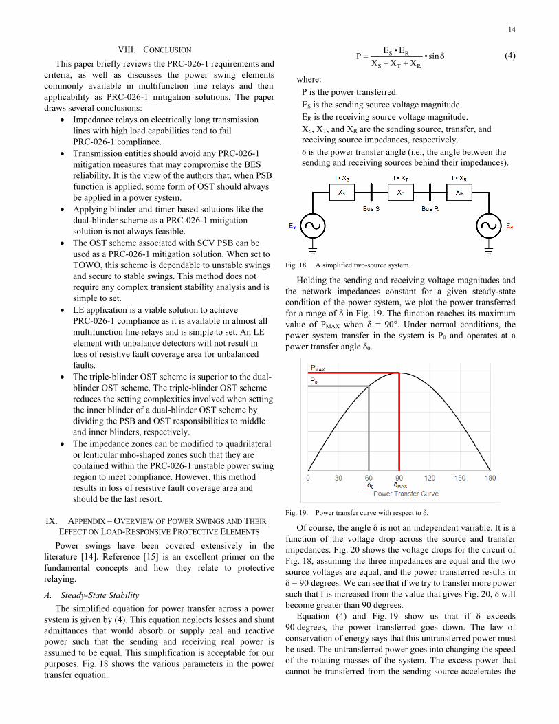
Holding the sending and receiving voltage magnitudes and the network impedances constant for a given steady-state condition of the power system, we plot the power transferred for a range of δ in Fig. 19. The function reaches its maximum value of PMAX when δ = 90°. Under normal conditions, the power system transfer in the system is P0 and operates at a power transfer angle δ0.
Fig. 19. Power transfer curve with respect to δ.
Of course, the angle δ is not an independent variable. It is a function of the voltage drop across the source and transfer impedances. Fig. 20 shows the voltage drops for the circuit of Fig. 18, assuming the three impedances are equal and the two source voltages are equal, and the power transferred results in δ = 90 degrees. We can see that if we try to transfer more power such that I is increased from the value that gives Fig. 20, δ will become greater than 90 degrees.
Equation (4) and Fig. 19 show us that if δ exceeds 90 degrees, the power transferred goes down. The law of conservation of energy says that this untransferred power must be used. The untransferred power goes into changing the speed of the rotating masses of the system. The excess power that cannot be transferred from the sending source accelerates the

15
sending portion of the system and the deficit power that was not transferred is made up by decelerating the receiving portion of the system. Because the speed of the sending and receiving systems is no longer the same, the systems will pull apart. If the situation is allowed to continue, the two systems lose synchronism. That is, they go out of step relative to each other.
Fig. 20. Voltages for the simplified circuit of Fig. 18.
We must operate the power system well away from a power transfer angle of 90 degrees. Consider that, in a complex power system, XT is made up of many parallel branches. If the system is operating near this state of maximum power transfer and a line opens, XT will increase, and the voltage drop across XT will push the power transfer angle past 90 degrees.
B. Transient Stability Thus far, we have only discussed steady-state conditions. In
transient stability, we often talk about 120 degrees being a good rule-of-thumb limit between stable and unstable power swings. How can we be stable if the angle between sending and receiving sources exceeds 90 degrees? We introduce the concept of the equal area criteria to explain this [16].
Consider that a fault on the power system is a temporary condition. A bolted fault reduces the voltage on the faulted phases to zero at the point of the fault and no power can be transferred across that path. This temporarily increases the XT term of (4) and creates a reduced power transfer curve while the fault is on the system. A multiphase fault has a much greater effect on XT than a single-phase fault because more phases are no longer able to transfer power. Reference [15] contains an excellent discussion on the effect of the various fault types on the power transfer equation.
Fig. 21 will be used to explain transient stability and the equal area criteria. Prior to the disturbance, a properly operating power system will be operating with a power transfer angle well below 90 degrees. This is point P0, δ0 in Fig. 21. At t0, a fault occurs on the power system. While the short circuit is on the system, the power transfer curve is reduced such that it is below the initial power flow level of P0. The state of the system immediately moves from the pre-/post-fault curve to the fault curve. The angle cannot move instantaneously, so at this instant it remains at δ0. Further, the power into the system cannot change instantaneously, so the power remains at P0. However, less power is now being transferred. The untransferred power results in accelerating the sending source and decelerating the receiving source which advances δ along the faulted system power transfer curve.
Fig. 21. A transiently stable system.
The fault is cleared at t1 and the power transfer is restored to the pre-/post-fault curve. By now, the power transfer angle has advanced to δ1. The power that is not transferred is stored as energy in the acceleration of the rotating mass of the sending source and given up from the deceleration of the rotational inertia of the receiving source. Energy equals power multiplied by time. While the x-axis of the power transfer curve is in degrees, it can be converted to time by the degrees per second that the angle advances. Thus, Area 1 on the transient stability plot is proportional to the total energy not transferred.
At the time the fault is cleared and the pre-/post-fault power transfer curve is restored, we can see that the power transferred at δ1 is now greater than the power into the system, P0. This excess power comes from decelerating the rotational mass of the sending source and is being absorbed by accelerating the rotational inertia of the receiving source. This continues until the power transfer angle reaches its extreme excursion of δ2 at t2. At this point, the power swing is arrested and the systems start pulling back together (δ is now decreasing).
At t2, the energy required to pull the systems back in synchronism represented by Area 2 is equal to the energy that caused the systems to pull apart represented by Area 1. The power transfer angle will oscillate along the pre/post fault power transfer curve until the system finally dampens out and reaches a new equilibrium state.
We can see from this discussion that transiently, δ can exceed the maximum power transfer angle of 90 degrees. If the power transfer conditions on the system at the initiation of the disturbance, P0, is operating with a δ0 that has little margin below 90 degrees, or if the fault is not cleared quickly to limit the untransferred energy represented by Area 1 that is pulling the systems apart, it is possible that Area 2 will not be large enough to offset Area 1. If δ advances beyond where the post-fault power transfer curve crosses P0, the power transferred becomes lower than the power into the system, the swing will not be arrested and the two machines will slip a pole with respect to one another.
The rule-of-thumb limit for the limit between a stable and unstable power swing, 120 degrees, is widely used. However, this is only a rule of thumb.
System operators use state simulators to ensure that the power system does not operate with power transfers near

16
δ = 90°. They study load and generation forecasts along with system outages and contingencies. Based on these tools, they can curtail certain generation and power transfers to keep the bulk power system operating with adequate margins.
C. Transient Stability Studies Of course, the bulk power system is much more complex
than this simple example. It constitutes many sources, branches, and loads. There are controls acting on the sources such that they dynamically change during the duration of a power swing. The only way to study power swings is to model the bulk power system and conduct computer simulation. However, while system planning engineers can model sources and their controls in detail, modeling loads is more uncertain. Further, modeling unconventional sources, which are making up an ever-larger portion of the bulk power system generation mix, is even more uncertain.
In every discussion of PSB and OST schemes, the literature always points to the importance of performing transient stability studies. Realistically, many portions of the bulk power system are too complex and the operating scenarios that might allow a major power swing are too varied to predict with any certainty. Most major disturbances occur due to operating conditions and a sequence of events that were never anticipated.
D. Power Swing Effect on Relays Now that we understand what power swings are, we need to
understand why load-responsive relays can trip on power swings. It should be obvious that a power swing results in extreme power flows and thus load-responsive relays cannot distinguish between normal power flow and power flow during a swing.
Of course, most faults are unbalanced whereas balanced three-phase faults are relatively rare. Though rare, our protection systems must be able to dependably detect and clear three-phase faults—especially given that an uncleared three-phase fault is most critical in causing a power swing in the first place. However, we can take advantage of the fact that most faults are unbalanced, and most modern relays bypass any load encroachment or power swing blocking supervision during unbalanced conditions to maximize dependability.
One way to visualize why distance relays are susceptible to operation on power swings is to first understand that for a distance relay, the voltage is a restraining signal and the current is an operate signal. Low voltage and high current can move the apparent impedance operating point inside the tripping characteristic. Any line terminals near the electrical center of the system will experience low voltage and high current flowing through their line during the swing.
Consider Fig. 22. We can see that as the angle δ between ES and ER grows due to the sending source accelerating and the receiving source decelerating, the voltage at the electrical center of the system, VES, gets smaller until eventually, if the systems become 180 degrees out of phase, it will become zero. Similarly, the driving voltage across the transfer impedance, VT, increases until, eventually, if the systems become 180 degrees out of phase, it will become two per unit. This high driving voltage causes high current to flow between the systems. To the distance relays, this phenomenon will appear to be a balanced fault.
Fig. 22 shows the case where ES and ER are equal. The electrical center of the system is at the exact mid-point of XS + XT + XR. If these voltages have different magnitudes, the electrical center of the system where VES will be zero at δ = 180° will appear closer or farther from the actual mid-point of XS + XT + XR. Thus, the actual swing trajectory on the impedance plane that a given relay will see is not only affected by the impedances of the network, it is also affected by the voltages of the various sources swinging relative to each other.
Fig. 22. Voltage at the electrical center and across the transfer impedance during a swing.

17
X. REFERENCES [1] NERC System Protection and Control Subcommittee Report,
“Protection System Response to Power Swings,” August 2013. [2] NERC Standard PRC-026-1 – Relay Performance During Stable Power
Swings. Available: nerc.com [3] T. Chang, M. Ajami, M. Chapariha, I. Anand, S. Alaeddini, “Challenges
in NERC PRC-026 Compliance Evaluation for a Complex Multi-Terminal Transmission Line,” proceedings of the 46th Annual Western Protective Relay Conference, Spokane, WA, October 2019.
[4] NERC Standard PRC-023-4 Transmission Relay Loadability. Available: nerc.com.
[5] NERC Standard PRC-025-2 – Generator Relay Loadability. Available: nerc.com.
[6] N. Fischer, G. Benmouyal, D. Hou, D. Tziouvaras, J. Byrne‐Finley, and B. Smyth, “Tutorial on Power Swing Blocking and Out‐of‐Step Tripping,” proceedings of the 39th Annual Western Protective Relay Conference, Spokane, WA, October 2012.
[7] G. Benmouyal, D. Hou, and D. Tziouvaras, “Zero-Setting Power-Swing Blocking Protection,” proceedings of the 31st Annual Western Protective Relay Conference, Spokane, WA, October 2004.
[8] SEL-T401L Ultra-High Speed Line Relay Instruction Manual. Available: selinc.com.
[9] J. Mooney and N. Fischer, “Application Guidelines for Power Swing Detection on Transmission Systems,” proceedings of the 32nd Annual Western Protective Relay Conference, Spokane, WA, October 2005.
[10] SEL-421 Protection, Automation, and Control System Instruction Manual. Available: selinc.com.
[11] IEEE PSRC Working Group D6, “Power Swing and Out-of-Step Considerations on Transmission Lines,” July 2005.
[12] Y. Xue, B. Kasztenny, D. Taylor, and Y. Xia, “Series Compensation, Power Swings, and Inverter-Based Sources and Their Impact on Line Current Differential Protection,” proceedings of the 66th Annual Conference for Protective Relay Engineers, College Station, TX, April 2013.
[13] E. O. Schweitzer, III, B. Kasztenny, A. Guzmán, V. Skendzic, and M. V. Mynam, “Speed of Line Protection – Can We Break Free of Phasor Limitations?” proceedings of the 68th Annual Conference for Protective Relay Engineers, College Station, TX, April 2015.
[14] E. W. Kimbark, Power System Stability, Volume II: Power Circuit Breakers and Protective Relays, Wiley, New York, NY, 1950.
[15] D. A. Tziouvaras and D. Hou, “Out-of-Step Protection Fundamentals and Advancements,” proceedings of the 57th Annual Conference for Protective Relay Engineers, College Station, TX, April 2004.
[16] C. L. Fortescue, “Transmission Stability Analytical Discussion of Some Factors Entering into the Problem,” Transactions of the American Institute of Electrical Engineers, Vol. 44, January 1925, pp. 984–1003.
XI. BIOGRAPHIES Pratheek Annamdevula received his B.Tech. degree in electrical and electronics engineering from GITAM University in Visakhapatnam, India, in 2014. He received his M.S. degree in electrical engineering from Michigan Technological University, Houghton, in 2017. Pratheek joined Schweitzer Engineering Laboratories, Inc. (SEL) in 2017 and is presently an application engineer specializing in protection.
Austin Thurman received his B.S. in electrical engineering from Southern Illinois University Edwardsville in 2018. He joined Schweitzer Engineering Laboratories, Inc. (SEL) in 2017 as an application engineering intern and is presently employed as a project engineer for SEL Engineering Services, Inc.
Michael Thompson received his B.S., magna cum laude, from Bradley University in 1981 and an M.B.A. from Eastern Illinois University in 1991. Upon graduating, he served nearly 15 years at Central Illinois Public Service (now AMEREN). Prior to joining Schweitzer Engineering Laboratories, Inc. (SEL) in 2001, he worked at Basler Electric. He is presently a Fellow Engineer at SEL Engineering Services, Inc. He is a senior member of the IEEE, Officer of the IEEE PES Power System Relaying and Control Committee, past chairman of the Substation Protection Subcommittee of the PSRC and received the Standards Medallion from the IEEE Standards Association in 2016. Michael is a registered professional engineer in six jurisdictions, was a contributor to the reference book Modern Solutions for the Protection Control and Monitoring of Electric Power Systems, has published numerous technical papers and magazine articles, and holds three patents associated with power system protection and control.
Brian Smyth received a B.S.E.E. and M.S.E.E. from Montana Tech at the University of Montana in 2006 and 2008, respectively. He joined Montana Tech as a visiting professor in 2008 and taught classes in electrical circuits, electric machinery, instrumentation and controls, and power system analysis. He joined Schweitzer Engineering Laboratories, Inc. (SEL) in 2009 as an associate power engineer in the research and development division. Brian is currently a development lead engineer in the transmission department. In addition to working for SEL, Brian joined Montana Tech in 2014 as an adjunct professor, where he teaches courses in power system protection. He received the Distinguished Alumni award from Montana Tech in 2016 and the IEEE Southwest Montana Chapter Engineer of the Year award in 2017. He is an active IEEE member and a registered professional engineer in the state of Washington.
Demetrios Tziouvaras was a professor at SEL University. He joined Schweitzer Engineering Laboratories, Inc. (SEL) in 1998 and has over 40 years of power system protection experience. Demetrios researched and developed advanced relaying algorithms for 15 years at SEL prior to joining SEL University. He previously worked at Pacific Gas and Electric Company for 18 years, where he held various protection engineering positions, including principal protection engineer. Demetrios holds five patents in the area of power system protection and has authored and coauthored more than 60 technical papers. He was a contributor to the reference book Modern Solutions for the Protection Control and Monitoring of Electric Power Systems. He is an IEEE senior member and a member of the Power System Relaying and Control Committee (PSRC). He is a member of CIGRE and an executive member of the U.S. National Committee of CIGRE. He received his B.S.E.E. from the University of New Mexico and M.S.E.E. from Santa Clara University. His main research interests are power system protection, control, and monitoring, and power system transients. Demetrios retired from SEL in December 2020.
© 2021 Schweitzer Engineering Laboratories, Inc. All rights reserved.
20210125 • TP6933-01