single event effects on digital integrated circuits ... seu and... · on digital integrated...
TRANSCRIPT
1
Single Event Effects
on digital integrated circuits:
Origins and Mitigation Techniques
Dr. Raoul VelazcoTIMA Laboratory
ARIS (Reliable Architectures of Integrated Systems)
Grenoble – Francehttp://tima.imag.fr
Ecole de Microélectronique et Microsystèmes
Fréjus, 19/5/2011
2
OUTLINE
1. Motivation
2. A description of SEE’s
3. Sources of SEE’s
4. Mitigation of SEE’s
5. Evaluating SEE sensitivity
6. Conclusions

3
• The microelectronic technology is constantly changing:
– higher density,
– faster devices,
– lower power.
• These increase the devices’ vulnerability to the effects
of radiation (not only in nuclear- space environments).
• In some applications, no failure is allowed.
• Future sub-micronic technologies are potentially
sensitive to the effects of atmospheric neutrons.
1. Motivations

4
2. A Description of SEE’s
Radiation and Electronic Devices
Displacement
T.I.D.
Accumulated
Single Particle S. E. E.
5
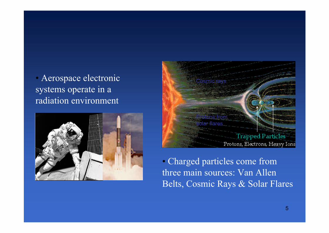
• Aerospace electronic
systems operate in a
radiation environment
• Charged particles come from
three main sources: Van Allen
Belts, Cosmic Rays & Solar Flares
Cosmic rays
Protons from
solar flares

6
• These increase the devices’ vulnerability to the
effects of radiation (nuclear and space
environments).
• Space Agencies favor the use of COTS
technologies.
• Future submicronic technologies are potentially
sensitive to the effects of atmospheric
neutrons.

7
2. A Description of SEE’s
What you always wanted to know about Single Event Effects (SEE’s)
• What are they?:One of the result of the interaction between the radiation and the electronic devices
• How do they act?:
Creating free charge in the silicon bulk that, in practical, behaves as a short-life but intense current pulse
• Which are the ultimate consequences?
From simple bitflips or noise-like signals until the physical destruction of the device

8
The Physical Mechanism
The incident particle generates a dense track of electron hole pairs and
this ionization cause a transient current pulse if the strike occurs
near a sensitive volume.
2. A Description of SEE’s
CHARGE
COLLECTION
VOLUME

9
2. A Description of SEE’s
The Classification of SEE’s
SINGLE EVENT UPSET (SEU): CHANGE OF DATA OF MEMORY CELLS
MULTIPLE BIT UPSET (MBU): SEVERAL SIMULTANEOUS SEU’S
SINGLE EVENT TRANSIENT (SET): PEAKS IN COMBINATIONAL IC’s
SINGLE EVENT LATCH-UP (SEL): PARASITIC THYRISTOR TRIGGER
FUNCTIONAL INTERRUPTION (SEFI): PHENOMENA IN CRITICAL PARTS
AND OTHERS…
HARD ERRORS vs SOFT ERRORS

10
2. A Description of SEE’s
CROSS SECTION (σ)
.
EVENTS
DEV
N
Part Fluenceσ =
LINEAR ENERGY TRANSFER (LET)
SOFT ERROR RATE: PROBABILITY OF AN ERROR AT USUAL CONDITIONS
FIT: Typical unit of SER � Probability of 1 ERROR every 109 h
E.g.- 180-nm SRAM: 1000-3000 FIT/Mb
Some Useful Definitions

11
3. Sources of SEE’sUsually, SEE’s have been associated with space missions
because of the absence of the atmospheric shield…
Cosmic rays
Protons from
solar flares
Unfortunately, our quiet oasis seems to be vanishing since
the enemy is knocking on the door…
• Alpha particle from vestigial U or Th traces
• Atmospheric neutrons and other cosmic rays
12
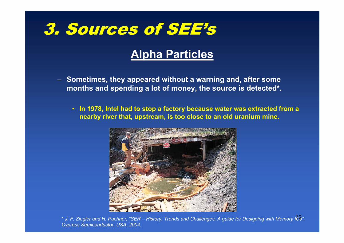
3. Sources of SEE’s
– Sometimes, they appeared without a warning and, after some
months and spending a lot of money, the source is detected*.
• In 1978, Intel had to stop a factory because water was extracted from a
nearby river that, upstream, is too close to an old uranium mine.
Alpha Particles
* J. F. Ziegler and H. Puchner, “SER – History, Trends and Challenges. A guide for Designing with Memory ICs”,
Cypress Semiconductor, USA, 2004.

13
3. Sources of SEE’s
– Sometimes, they appeared without a warning and, after some
months and spending a lot of money, the source is detected*.
• In 1986, IBM detected a high rate of useless devices and related it to
the phosphoric acid, the bottles of which were cleaned with a 210P
deionizer gadget…hundreds of kms far.
Alpha Particles
* J. F. Ziegler and H. Puchner, “SER – History, Trends and Challenges. A guide for Designing with Memory ICs”,
Cypress Semiconductor, USA, 2004.

14
3. Sources of SEE’s
– Sometimes, they appeared without a warning and, after some
months and spending a lot of money, the source is detected*.
• In 1992, the problem came from the use of bat droppings living in
cavern with traces of Th and U to obtain phosphorus.
Alpha Particles
* J. F. Ziegler and H. Puchner, “SER – History, Trends and Challenges. A guide for Designing with Memory ICs”,
Cypress Semiconductor, USA, 2004.

15
3. Sources of SEE’s
– But sometimes, we are a little naive…
• Solder balls are usually made from Sn and Pb, which come from
minerals where there may be uranium and thorium traces.
Nevertheless, the designer forgets this detail and places
the solder balls too close to critical nodes!
Alpha Particles
16
3. Sources of SEE’s
– Fortunately, they are easily controlled following some simple rules
during the manufacturing process.
But, sometimes, the enemy strikes back!
In 2005, a figure of 2·106 FIT/Mbit was observed in the SRAMs
attached to pacemakers where:
– the package had been removed by cosmetic reasons
– And the solder balls had not been previously purified*.
Fortunately, nobody deceased (We cross our fingers).
Alpha Particles
* J. Wilkinson, IEEE Trans. Dev. Mat. Reliab., 5 (3), pp. 428-433, 2005

17
3. Sources of SEE’s
Usually, they had been a headache for the designers of
electronics boarded in space missions…
Here you are some of their practical jokes*…
• Cassini Mission (1997).- Some information was lost because of MBUs.
• Deep Space 1.- An SEU caused a solar panel to stop opening out.
• Mars Odyssey (2001).- Two weeks after the launch, alarms went off
because some errors lately attributed to an SEU.
• GPS satellite network.- One of the satellites is out of work, probably
because of a latch-up.
Cosmic Rays
* B. E. Pritchard, IEEE NSREC 2002 Data Workshop Proceedings, pp. 7-17, 2002
18
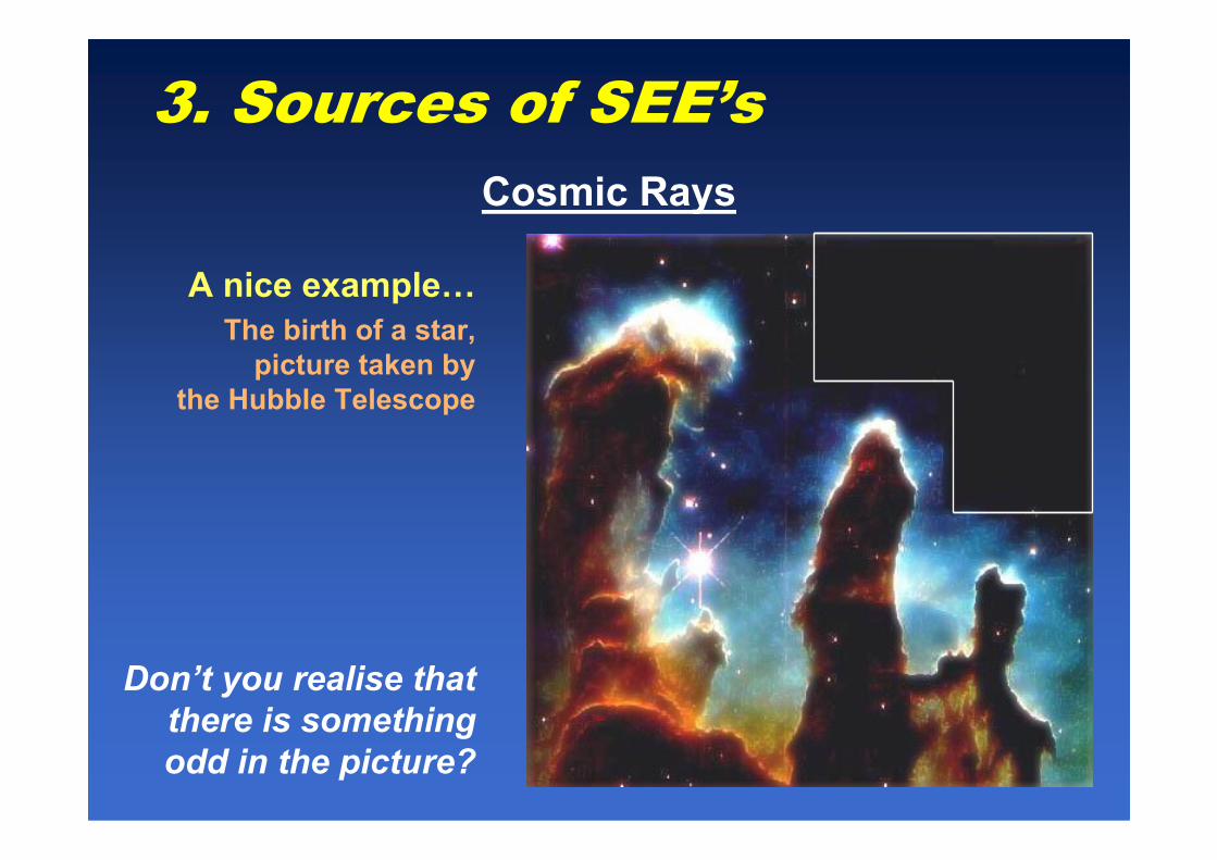
3. Sources of SEE’s
A nice example…
The birth of a star,
picture taken by
the Hubble Telescope
Cosmic Rays
Don’t you realise that
there is something
odd in the picture?

19
3. Sources of SEE’s
• The highest fluence is reached between 15-20 km of altitude.
• Less than 1% of this particle rain reaches the sea level.
• The composition has also changed…
• Basically, neutrons and some pions
Usually, the neutron flux is referenced to that of New York City, its
value been of (in appearance) only 15 n/cm2/h
• This value depends on the altitude (approximately, x10 each 3 km until
saturation at 15-20 km).
• And also on latitude, since the nearer the Poles, the higher rate.
• South America Anomaly (SAA), close to Argentina
• 1.5 m of concrete reduces the flux to a half.
What a weak foe, really should be we afraid of?
Cosmic Rays at Ground Level
20
3. Sources of SEE’s
Perhaps, we may believe that we are in a safe shelter but…
– 1992.- The PERFORM system, used by airplanes to manage the taking-off manoeuvre had to be suddenly replaced because of the SEUs in their SRAMs*.
– 1998.- A study reported that, every day, the 1 out of 10000 SRAMs attached to pacemakers underwent bitflips**.
This factor being 300 times higher if the patient had taken an transoceanic aircraft.
Cosmics Rays at Ground Level
* J. Olsen, IEEE Trans. Nucl. Sci., 1993, 40, 74-77
** P. D. Bradley, IEEE Trans. Nucl. Sci., 45 (6), 2829-2940

21
3. Sources of SEE’s
– The call of the Thousand (2000).- Sun Unix server systems crashed in dozens of places all over the USA because of SEU’s happening in their cache memory, costing several millions of dollars*.
– 2005.- After 102 days, the ASC Q Cluster supercomputer showed 7170 errors in its 81-Gb cache memory, 243 of which led to a crash of the programs or the operating system**.
Cosmic Rays at Ground Level
* FORBES, 2000
** K. W. Harris, IEEE Trans. Dev. Mat. Reliab., 2005, 5, 336-342

22
3. Sources of SEE’s
Why these exotic phenomena are appearing at lower and lower altitude?
The present trend is to minimise the
typical layout length.
This has helped to decrease the
sensitive volume but, also, the critical
charge does.
Most pessimistic simulations show a rock-bottom at 130-180 nm and a sudden
increase is expected for more advanced technologies.
Cosmic Rays at Ground Level
T. Granlund, IEEE Trans. Nuc. Sci., 2003, 50, 2065-2068
23
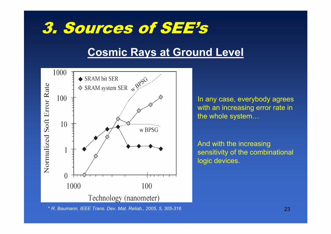
3. Sources of SEE’s
In any case, everybody agrees
with an increasing error rate in
the whole system…
And with the increasing
sensitivity of the combinational
logic devices.
Cosmic Rays at Ground Level
* R. Baumann, IEEE Trans. Dev. Mat. Reliab., 2005, 5, 305-316

24
3. Sources of SEE’s
Can this background be worse?
Yes, it can. Some details may increase the neutron sensitivity.
– Power supply values.- The lower, the more likely the SEU’s
– Frequency of work.- SEU’s are more dangerous while the system
is reading or writing.
– Presence of Boron.- There is an isotope of boron, 10B, able to trap
low energy thermal neutrons and release an energetic alpha
particle.
– Altitude
10 1 4 7
5 0 2 3B n Liα+ → +
Cosmic Rays at Ground Level

25
4. Mitigation of SEE’sFirst of all, Where must we expect SEEs?
– All the combinational stages are supposed to be affected by
SETs.
– Everything having SRAM cells is a candidate to show SEUs,
MBU’s:
– SRAM’s, Microprocessors, FPGAs, ASICs, etc.
– Other devices seem to be quite SEE-tolerant because of
their way of building:
– DRAMs, PSRAMs, NAND memories, etc.
Which are the strategies to mitigate SEE’s?
1. Technological
2. Design
3. Software and Hardware Redundancy

26
4. Mitigation of SEE’s
– First Option: Removal of widely-used BPSG layer
• Used for planarization between metallic layers.
• If removed, the chance of SEUs is 8-10 times lower.
• The use of PSG process is recomended.
– If this removal were not possible, we may minimise the SEU
incidence by means of:
1. Boron purification.- Only 20% of natural boron is 10B,
the rest being 11B, insensitive to neutrons.
2. Cover the IC with a 3-mm B4Si3 layer, which absorbs
most neutrons and emits the alpha particles far from
the critical nodes.
Technological Strategies

27
4. Mitigation of SEE’s
– Second Option: Redesign the IC in SOI technology.
• SOI technology has a tolerance five times higher than that of same typical length bulk technology.
Technological Strategies
R. Baumann, 2005 NSREC Short Course
28
4. Mitigation of SEE’s
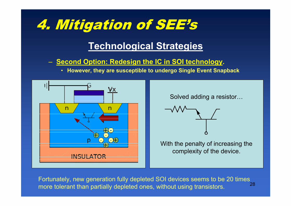
– Second Option: Redesign the IC in SOI technology.
• However, they are susceptible to undergo Single Event Snapback
Fortunately, new generation fully depleted SOI devices seems to be 20 times
more tolerant than partially depleted ones, without using transistors.
Solved adding a resistor…
With the penalty of increasing the
complexity of the device.
Technological Strategies

29
4. Mitigation of SEE’s
– Third Option: Managing the doping profile.
• If SOI technologies are not available,
• The doping profile can be modified to create wells
• Thus, the charge collection area shrinks.
The drawback is that there must be an additional layer as well as an extra
thermal cycle… to reduce the sensitivity only to 25-50%
Collection Volume
(No Buried Impl.)
Collection Volume
(Buried Impl.)
Technological Strategies

30
4. Mitigation of SEE’s
Instead of using typical circuits, let us try to improve them.
Example: A SRAM cell
Sensitive nodes
Design Strategies

31
4. Mitigation of SEE’s
Sometimes, the cell may be hardened adding some resistors.
Penalties: Actually, we have added a LP filter � Frequency behaviour worsens
Design Strategies

32
THE DICE CELL
4. Mitigation of SEE’s
Or, to feed-back the cell to minimise the action of the single
events…
THE HIT CELL
Design Strategies
33
4. Mitigation of SEE’s
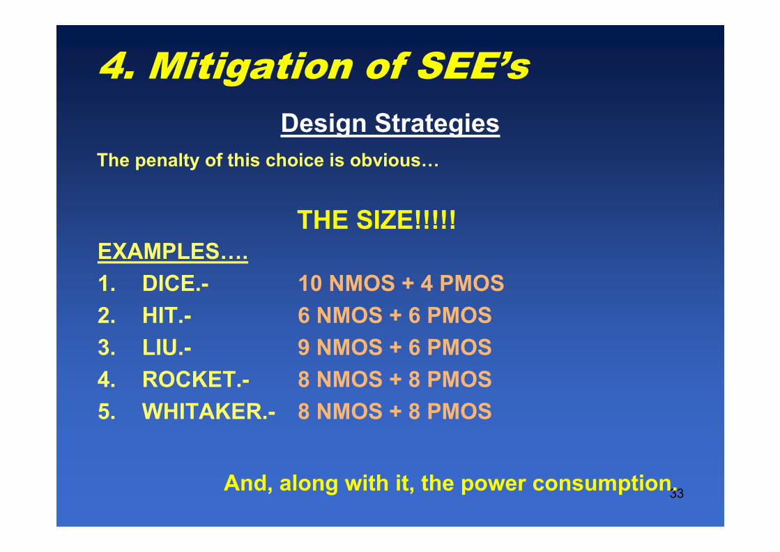
The penalty of this choice is obvious…
THE SIZE!!!!!EXAMPLES….
1. DICE.- 10 NMOS + 4 PMOS
2. HIT.- 6 NMOS + 6 PMOS
3. LIU.- 9 NMOS + 6 PMOS
4. ROCKET.- 8 NMOS + 8 PMOS
5. WHITAKER.- 8 NMOS + 8 PMOS
And, along with it, the power consumption.
Design Strategies

34
4. Mitigation of SEE’s
Your strategies, if you don’t feel like redesigning all
your chips.
SIX OPTIONS TO CHOOSE…
• Use of Error Correction Codes
• Interleaving Bits
• Periodical Refresh or Resetting.
• Triple Modular Redundancy (TMR)
• Time Redundancy
• Software Redundancy
THEY DO NOT EXCLUDE EACH OTHER!
Software and Hardware Redundancy Strategies

35
4. Mitigation of SEE’s
Error Correction Codes (ECC-EDAC)
Fundamentals: Instead of saving the data as they are, they are
stored making use of an error correction code (E. g. Hamming)
Advantages
• Easy implementation
• Able to detect and correct all the SEUs.
Drawbacks
• The effective memory size decreases.
– To codify 64 bits, 8 extra bits are needed.
• Cannot correct any sort of MBUs.
– They are 2% of typical radiation induced SEUs.
• What happens if the coder or the decoder fails?
Software and Hardware Redundancy Strategies

36
4. Mitigation of SEE’s
Interleaving Bits
Fundamentals: MBU’s usually affect adjacent memory cells.
Therefore, never should neighbour cells be used.
Advantages
• Higher MBU tolerance
Drawbacks
• The effective memory size decreases to a half.
• We insist… What happens if the coder or the decoder fails?
Software and Hardware Redundancy Strategies

37
4. Mitigation of SEE’s
Periodical Refresh and Resetting
Fundamentals: In systems with a large amount of FPGA’s or
microprocessors, the programs will be periodically reloaded.
Advantages
• Easy to implement
• Easy to maintain and update.
Drawbacks
• Only for huge systems with a large amount of devices where, in
case some of them fails, the whole system does not crash.
• Obviously, the backup copy of the program must be radiation-
tolerant.
Software and Hardware Redundancy Strategies

38
4. Mitigation of SEE’s
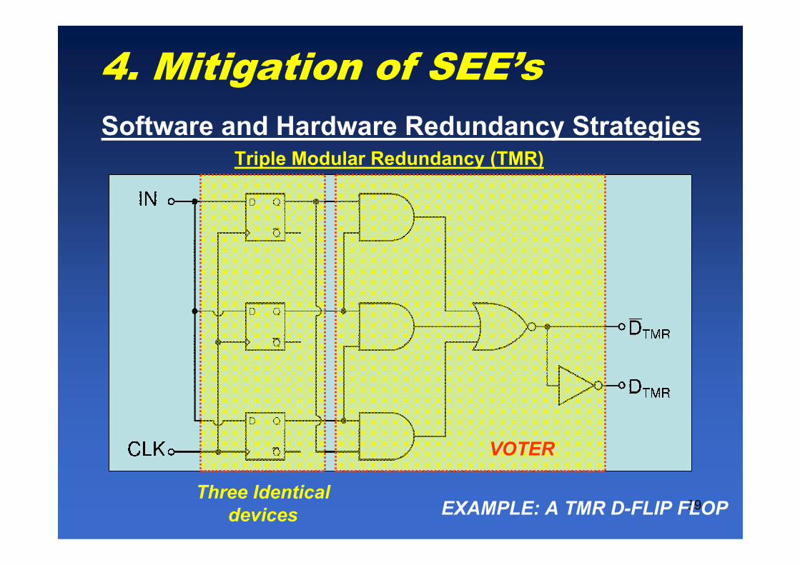
Triple Modular Redundancy (TMR)
Fundamentals: Three devices will do the same task and a block
selects the most “popular” output.
0000
0100
0010
1110
0001
1101
1011
1111
VSCBA
System A
System B
System C
INPUT BUS
VOTING SYSTEM
A
B
C
VS
VOTING SYSTEM
Software and Hardware Redundancy Strategies
39
Triple Modular Redundancy (TMR)
EXAMPLE: A TMR D-FLIP FLOPThree Identical
devices
VOTER
4. Mitigation of SEE’s
Software and Hardware Redundancy Strategies

40
4. Mitigation of SEE’s
Triple Modularity Redundacy (TMR)
Advantages
• Easy to implement
• Some tools are available for FPGA’s and CPLD’s.
Drawbacks
• The size of the design is x3
• Sometimes, only some critical blocks should be hardened.
• A little decrease in the circuit speed due to the new stage
• What happens if the voter fails?
• Should we add more and more voter stages?
Software and Hardware Redundancy Strategies

41
Therefore, if you are an insecure designer…But be careful and do not become a paranoid…
4. Mitigation of SEE’s
Triple Modularity Redundacy (TMR)
If we go on, we’ll end up
using an FPGA
to mimic a flip-flop!!!!
Software and Hardware Redundancy Strategies

42
Fundamentals:
Instead of using three blocks, let us use several times the same system.
4. Mitigation of SEE’s
Time Redundancy
SOME EXAMPLES…
Software and Hardware Redundancy Strategies

43
1.- TMR with delayed inputs
Drawbacks
• T > TSE & TCK1 = 4·T
4. Mitigation of SEE’s
Time Redundancy
Software and Hardware Redundancy Strategies
44
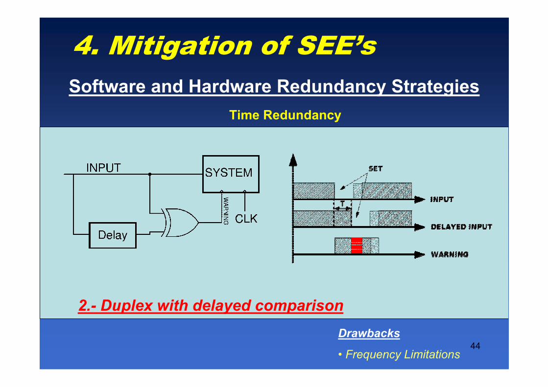
2.- Duplex with delayed comparison
Drawbacks
• Frequency Limitations
4. Mitigation of SEE’s
Time Redundancy
Software and Hardware Redundancy Strategies

45
Fundamentals: Modifications of the program adding check and correctioncapabilities (duplication of data and instructions, temporal redundancy, etc.) of SEU’s
Advantages
• It allows to harden any device (From PIC’s to PowerPC’s)
• Detects more than 90% of anomalous program behaviour.
Drawbacks
• The programmation is not so simple.
• The size of the program soars up to 3-4 times the original one.
4. Mitigation of SEE’s
Software Redundancy*
Software and Hardware Redundancy Strategies
* M. Rebaudengo et al. “Coping with SEUs/SETs in microprocessors by means of low-cost solution”,
IEEE Trans. Nuc. Sci., 49 (3), 2002, pp. 1491-1495

46
The devices has been built but…
How to determine their sensitivity to SEE’s?
There are some ways of finding it out…
• Life tests
• Accelerated radiation ground tests
• Fault injection
5. Evaluating SEE sensitivity
47
5.1 Evaluating SEE sensitivity
Fundamentals: Gathering a high number of devices to increasethe total number of SEE’s, valid statistical results are obtained.
Advantages
• Devices are tested where they are supposed to work
• The only actual and trustworthy results
Drawbacks
• Large amount of devices (cost, power consumption, facility)
• Longtime to obtain good results
• Influenced by the aleas of the sun activity
Life Tests
48
a) Evaluating SEE sensitivity: Experiments on-board satellites
• MPTB (Microelectronics and Photonics Testbed), on
board a satellite from Naval Research Labs
(launched in 1996).
• LWS/SET (Living With a Star, Space Environment
Testbed), on board a satellite from NASA (GFSC), to
be launched in 2011.
• SARE (Satélite de imagenes de Alta Resolucion), on
board a satellite from CONEA, to be launched in 2012

49
Flight model of COTS2 experiment devoted to
flight in LWS/SET: A fault tolerant
cryptoprocessor implemented in Virtex II FPGA.

50
b) Evaluating SEE sensitivity in the earthatmosphere
• The SEEs may occur in advanced ICs as the consequence of
the thermal neutrons present in the atmosphere
• At ground level the probabilities of suffering a SEE are very low
due to the low neutron’s fluxes 13 neutrons/cm2xhour
• With the altitude the neutron’s fluxes significantly grow:
at the altitudes of commercial flights the flux is about
800 neutrons/cm2xhour.
=> To get a feedback about the sensitivity to SEE in reasonable
time: the number of exposed ICs must be significant and they
should be implemented at high altitude.
An example: the ASTEP (Altitude SEE Test European Platform)
– Pic de Bures (2552 m), French Alps
– 130 nm & 5 Gb SRAMs ���� 10 SEU/month
– Operational since March 2006

51
b) Evaluating SEE sensitivity in the earthatmosphere: The Rosetta project
A test board devoted to evaluate the sensitivity of
advanced microelectronic devices to atmospheric
radiation was installed in three sites:
- IRAM (Inst. de RadioAstronomie Millimetrique)
- L2MP Lab, Marseille
- LSBB (Lab. Souterrain Bas Bruit)

52
The Rosetta project (cnt’d)
ROSETTA experiment will last 3 years
LSBB: Lab. Souterrain Bas Bruit IRAM Lab at Pic de Bure

53
The Rosetta project (cnt’d)
The test board includes 200 Xilinx FPGAs (200 Mbit/device)

54
The Rosetta project (cnt’d)
Preliminary results:
• Virtex-4 FPGA 246 FIT/Mb 352 FIT/Mbit
• Virtex-5 FPGA 151 FIT/Mbit 635 FIT/Mbit
Virtex-4: Config. SRAM 130 nm, Block RAM 90 nm
Virtex-5: 90 nm, 65 nm

55
Goal: Get evidences of SEUs occuring in the earth’satmosphere.
Means: A test platform suitable to operate at high altitude
Target circuits: Advanced memories (SRAM, DRAM, ...)
Achieved steps: Validation of the experiment’s logistic
c) A generic platform for high altitudelife-test
56
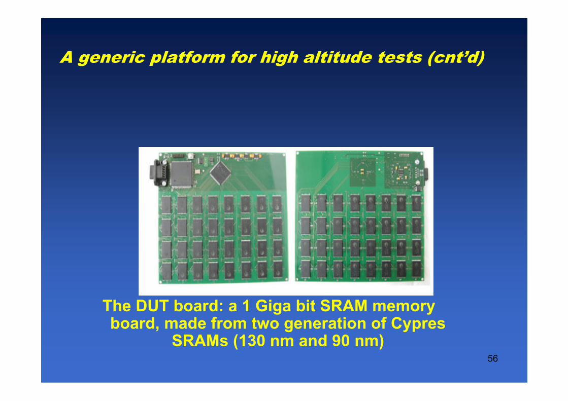
The DUT board: a 1 Giga bit SRAM memoryboard, made from two generation of Cypres
SRAMs (130 nm and 90 nm)
A generic platform for high altitude tests (cnt’d)

57
The DUT board: a 1 Giga bit SRAM memory board, made from twogeneration of Cypres SRAMs (130 nm and 90 nm)
Address FPGAControl FPGA

58
DUT board Architecture

59
The test platform was activated during some flights:
- NYC���� LIMA ( 8 hours): An SEU
[14/10/2008 14:41:09] - Read data
00 82 C1 1A 45 55 the chip is a SRAM Cypress (90 nm).
- Madrid���� Buenos Aires (start at 14H30):
SEUs and MBUs observed:
[5/12/2007 17:10:42] - Read data
03 B6 57 F6 55 57 ------------------ 1 SEU
03 B6 57 FA D5 57 ------------------ 2 SEUs in the same byte
03 B6 57 BE F5 57 ------------------ 3 SEUs in the same byte
Some results obtained during flights
• The platforms have 1Gbit of SRAM. One of them includes 16 chips
in 90 nm and 48 chips in 130 nm
• A typical SEU log includes 6 bytes:
memory chip (1 byte), address (2 bytes), data read (2 byte)

60
- Buenos Aires ���� Madrid (flight started at 14H30): an MBU observed[14/12/2007 11:30:58] - Read data
00 FA E3 34 55 15
00 FA E3 38 55 15
00 FA E3 3C 55 15
- Amsterdam ���� Los Angeles an MCU observed
[12/4/2008 16:27:32] - Read data
02 14 7E C3 5D 55
02 15 7E C2 5D 55
• In October 2008 the platform was installed at 3800 mts in the city of Cusco (Peru)
- an SEU and a SEFI were observed
Some results obtained during flights (cont’d)

61
Objectives:• Obtain the know-how to perform this kind of experiment
and develop a generic platform that can be reused and adapted to test different devices.
• Collect different kind of data (internal and external temperature, humidity, altitude, pressure, GPS location, etc.) that can be used to correlate with the results of the experiments.
• Final goal is to collect, fast and at affordable cost, experimental data about the effects of natural radiation on advanced microelectronic circuits.
Balloon experiments

62
Two balloons were launched in 2008 in Uruguay (April 24th and October 25th)
Balloon experiments (cont’d)
63
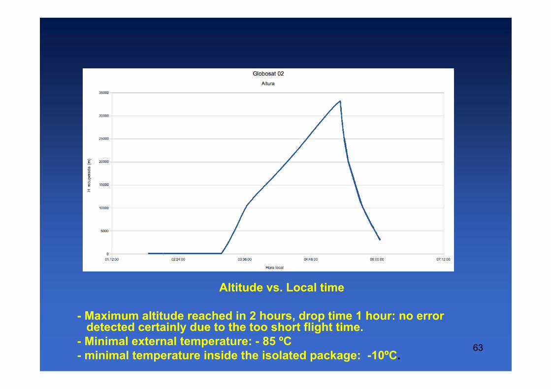
Altitude vs. Local time
- Maximum altitude reached in 2 hours, drop time 1 hour: no error detected certainly due to the too short flight time.
- Minimal external temperature: - 85 ºC
- minimal temperature inside the isolated package: -10ºC.

64

65
Fundamentals: The more particles hit the circuits, the more eventsare recorded.
They need:
• a particle beam, which can be obtained by Radiation Facilities :
– particle accelerators: cyclotrons, linear accelerators,...
– equipments based on fission decay sources such as Cf252
– laser beams
• test methodology, defining the activity of the device under test (DUT)
• an electronic test equipment for controlling and observing the
behavior of the DUT during its exposition to radiation.
• and.... a deep expertise and ...good luck
5.2 Evaluating SEE sensitivity
Accelerated Radiation Ground Tests

66
Advantages
• Significant results in short time (some hours)
• Reproducible
Drawbacks
• Devices are “activated” so they can’t be immediately handled.
• Particle beam energy spectrum is not really that of the nature
radiation.
• Few facilities along the world.
• Lower cost in devices, higher cost in the experiment set-up
Main result is the SEE static cross section, a worst case far from the
real sensitivity of the final application
5. Evaluating SEE sensitivity (cnt’d)
Accelerated Radiation Ground Tests
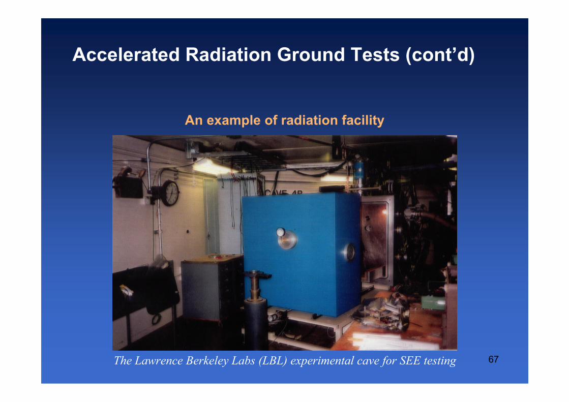
67The Lawrence Berkeley Labs (LBL) experimental cave for SEE testing
An example of radiation facility
Accelerated Radiation Ground Tests (cont’d)
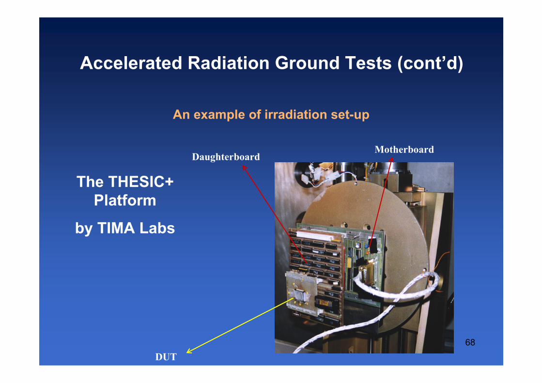
68
DUT
DaughterboardMotherboard
The THESIC+
Platform
by TIMA Labs
An example of irradiation set-up
Accelerated Radiation Ground Tests (cont’d)

69
Fundamentals: The consequence of the incident particle can be simulated by HW or SW means.
Appropriate for FPGA’s and microprocessors-based architectures
Once a radiation test has been performed and the static cross section
is determined:
• A program is loaded in the DUT and launched.
• During the execution, errors are injected by suitable means
(hardware, software) in the target device following a realistic
statistical distribution inferred from the cross section.
5.3 Evaluating SEE sensitivity
Fault Injection Tests

70
• Step 1: Radiation ground testing in a suitable facility:
static SEU cross-section given in cm2
σSEU = #upsets / #particles ( cm2)
How many particles to provoke an upset ?
For a processor-based architecture :
• Step 2: Fault injection sessions (off-beam upset simulation):
τinj = #errors / #upsets
How many upsets to provoke an error in the studied
application?
5.3 Evaluating SEE sensitivity
Fault Injection Tests (cont’d)

71
• Error rate estimation:
ττττSEU= σσσσSEU* ττττinj [errors/particle]
• Application error rate
ττττSEU*Expected particle fluency [errors/time unit]
5. Evaluating SEE sensitivity
Fault Injection Tests (cont’d)

72
An example…
• Measured and predicted dynamic cross sections for an 8051
microcontroller executing a matrix multiplication program
• SEU’s were injected by HW means using the asynchronous interrupt signal
1,0E-06
1,0E-05
1,0E-04
1,0E-03
1,0E-02
1,0E-01
2,97 5,85 12,7 14,1 12,7 12,7 34 40,7
LET [MeV/mg/cm²]
Taux d'erreurs (cm² / composant)
Prédit Mesuré
5. Evaluating SEE sensitivity
Fault Injection Tests (cont’d)

73
Advantages
• The SEU occurrence instant x location space can be
exhaustively explored
• Experimentation can follow the application updates
Drawbacks
• Some SEU targets are not accessible.
• If faults are injected by SW, need for a corresponding HDL
model.
• If injected by hardware, a prototype is needed.
5. Evaluating SEE sensitivity
Fault Injection Tests (cont’d)

74
• ICs issued from advanced microelectronic technologies
are sensitive to the natural radiation.
• Their reliability and security are threatened.
• Some techniques to deal with such a conjuncture exist
but faults due to radiation remain a high concern.
• A platform for high altitude experiments was developed
in the frame of ALFA Nicron project
• Preliminary data was obtained in flights
• The logistic of balloon experiments was validated after
two launches done in Uruguay
6. Conclusions
75
• Perform two more balloon experiments (SEUs expected !).
• Perform laser experiments to get physical vs. logical
address and confirm MBUs observed.
• Perform a static balloon launch (cooperation with CNES).
• Develop an experiment devoted to operate in a satellite:
project SARE from CONAE, Argentine.
• Final goal: Confront SEU data observed in altitude
experiments with data predicted from models
6. Perspectives

76
• IEEE NSREC (Nuclear & Space Radiation Effects Conf)
• IEEE RADECS (Radiation Effects on iC’s and Systems)
• IEEE IOLTS (Int. On-Line Test Symposium)
• IEEE LATW (Latin American Test Workshop)
• SERESSA (int. School on the Effects of Radiation on
Embedded Systems for Space Applications)
7. Main conferences and workshopsrelated with this topic

77
To those that survived from this talk without a
temporary brain single event latch-up,
THANK YOU FOR YOUR ATTENTION!
Those dozing off, please wake up, it’s the
TIME FOR QUESTIONS