smart facade tool manual
TRANSCRIPT
Smart Facade Tool
User ManualA powerful tool for facadeboard design in Archicad.
Cembrit Tepro ABBox 42013S-126 12 StockholmTel 08-506 608 00Fax 08-506 608 [email protected]
www.cembrit.se
INBRIX AB 2007-2009
Smart Facade ToolVersion 1.4
2009.02.20
Start
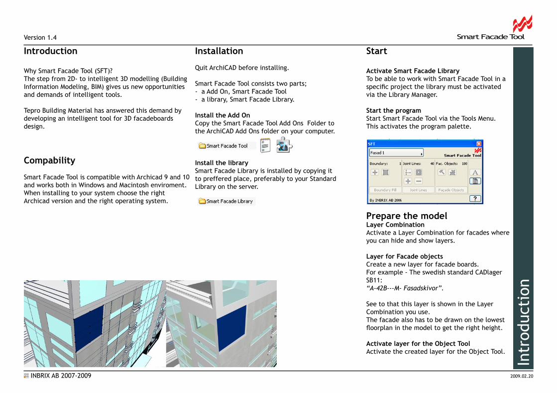
Activate Smart Facade LibraryTo be able to work with Smart Facade Tool in a specific project the library must be activated via the Library Manager.
Start the programStart Smart Facade Tool via the Tools Menu. This activates the program palette.
Prepare the model Layer CombinationActivate a Layer Combination for facades where you can hide and show layers.
Layer for Facade objectsCreate a new layer for facade boards.For example - The swedish standard CADlager SB11:“A-42B---M- Fasadskivor”.
See to that this layer is shown in the Layer Combination you use.The facade also has to be drawn on the lowest floorplan in the model to get the right height.
Activate layer for the Object ToolActivate the created layer for the Object Tool.
Introduction
Why Smart Facade Tool (SFT)?The step from 2D- to intelligent 3D modelling (Building Information Modeling, BIM) gives us new opportunities and demands of intelligent tools.
Tepro Building Material has answered this demand by developing an intelligent tool for 3D facadeboards design.
Compability
Smart Facade Tool is compatible with Archicad 9 and 10 and works both in Windows and Macintosh enviroment. When installing to your system choose the rightArchicad version and the right operating system.
Installation
Quit ArchiCAD before installing.
Smart Facade Tool consists two parts;- a Add On, Smart Facade Tool- a library, Smart Facade Library.
Install the Add OnCopy the Smart Facade Tool Add Ons Folder to the ArchiCAD Add Ons folder on your computer.
Install the librarySmart Facade Library is installed by copying it to preffered place, preferably to your Standard Library on the server.
Intr
oduc
tion
INBRIX AB 2007-2009
Smart Facade ToolVersion 1.4
2009.02.20
The Concept
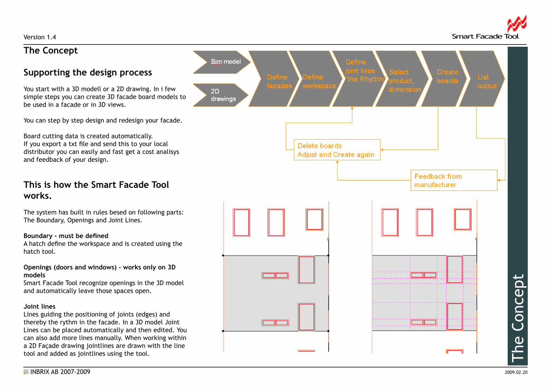
Supporting the design process
You start with a 3D modell or a 2D drawing. In i few simple steps you can create 3D facade board models to be used in a facade or in 3D views.
You can step by step design and redesign your facade.
Board cutting data is created automatically.If you export a txt file and send this to your local distributor you can easily and fast get a cost analisys and feedback of your design.
The
Conc
ept
This is how the Smart Facade Tool works.
The system has built in rules besed on following parts: The Boundary, Openings and Joint Lines.
Boundary - must be definedA hatch define the workspace and is created using the hatch tool.
Openings (doors and windows) - works only on 3D modelsSmart Facade Tool recognize openings in the 3D model and automatically leave those spaces open.
Joint linesLines guiding the positioning of joints (edges) and thereby the rythm in the facade. In a 3D model Joint Lines can be placed automatically and then edited. You can also add more lines manually. When working within a 2D Façade drawing jointlines are drawn with the line tool and added as jointlines using the tool.
INBRIX AB 2007-2009
Smart Facade ToolVersion 1.4
2009.02.20
Smart Facade Tool Palette
New Facade.... Create / admin / edit / delete Boundary Define workspace
Joint Lines Guidelines to control the rhythm of the board sizes and placements Add Delete Mark
Fac. Objects ( Facade Objects) Board Object Settings Create Mark Export to Precut. File which can be analyzed by Tepro. (Cutting program)
Automatic Joint Line Placer Create jointlines automatically from openings in the 3Dmodell.
Littera - Text settings Option to hide/show text id on the boards and to set text size.
Link to this Manual/Help.
1
12
3
2 3
4
4
5
6 7
5
6
7
Pale
tte
8
8
INBRIX AB 2007-2009
Smart Facade ToolVersion 1.4
2009.02.20
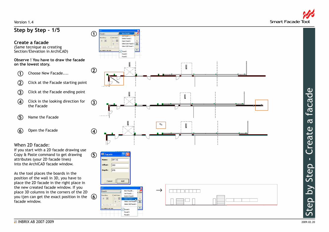
Step by Step - 1/5
Create a facade(Same tecnique as creating Section/Elevation in ArchiCAD)
Observe ! You have to draw the facade on the lowest story.
Choose New Facade.... Click at the Facade starting point
Click at the Facade ending point
Click in the looking direction for the Facade
Name the Facade
Open the Facade
When 2D facade:If you start with a 2D facade drawing use Copy & Paste command to get drawing attributes (your 2D facade lines) into the ArchiCAD facade window.
As the tool places the boards in the position of the wall in 3D, you have to place the 2D facade in the right place in the new created facade window. If you place 3D columns in the corners of the 2D you tjen can get the exact position in thefacade window.
1
2
3
4
5
1
2
3
4
5
6
6
Step
by
Step
- C
reat
e a
faca
de
INBRIX AB 2007-2009
Smart Facade ToolVersion 1.4
2009.02.20
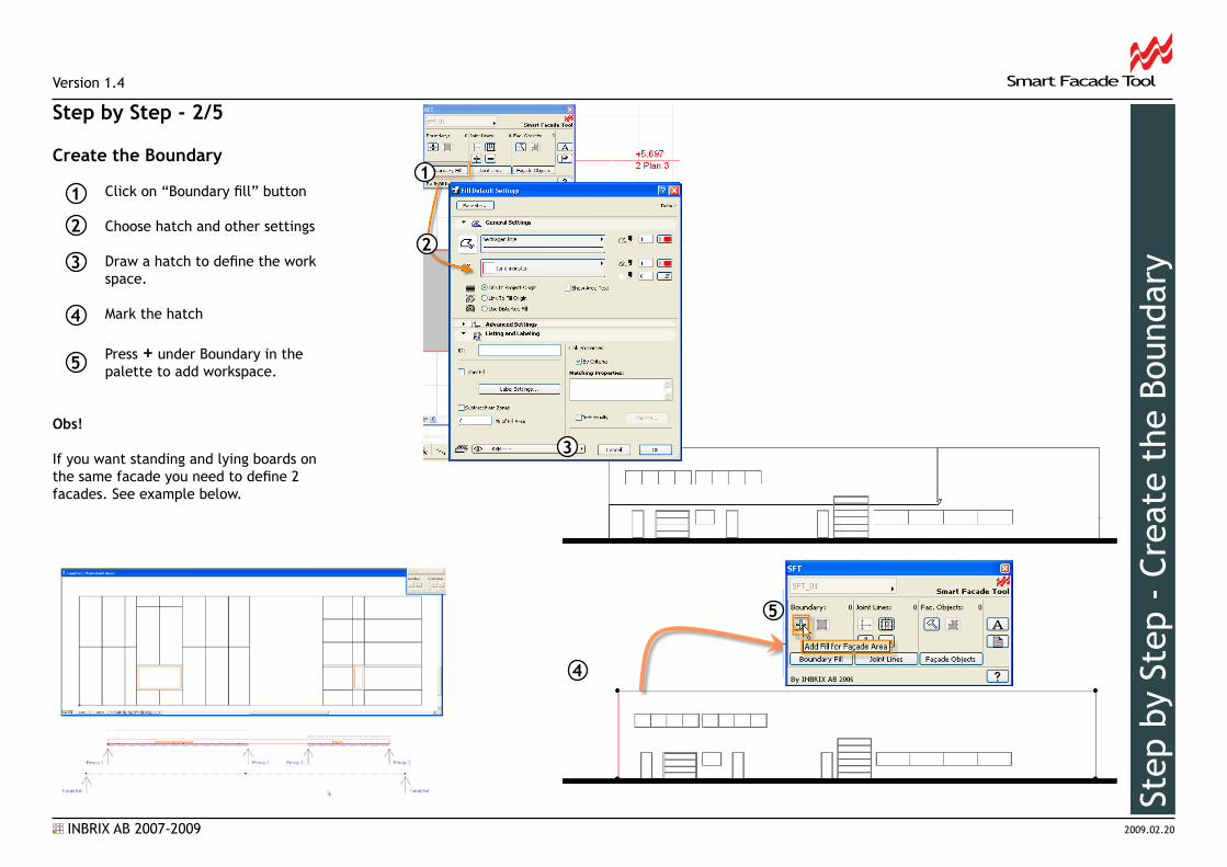
Step by Step - 2/5
Create the Boundary
Click on “Boundary fill” button Choose hatch and other settings
Draw a hatch to define the work space. Mark the hatch
Press + under Boundary in the palette to add workspace.
Obs!
If you want standing and lying boards on the same facade you need to define 2 facades. See example below.
2
3
4
5
11
2
3
4
5
Step
by
Step
- C
reat
e th
e Bo
unda
ry

INBRIX AB 2007-2009
Smart Facade ToolVersion 1.4
2009.02.20
Step by Step - 3/5
Create the Joint lines.
With this feature you create guidelines to define the basic rules for boards size and rhythm .
Start by choosing line type and line colour via the button “Joint Lines” Tip! Dashed and light red.
Create lines for the joints of the boards.
A good method is the “Automatic Joint Line Placer” witch places Joint Lines automatically on the Facade. The lines then can be edited by drag a copy and multiply. Use ArchiCAD standard functions . This function only works with a 3D model. If you choose to draw more lines these must be marked and added
with the + in the palette. This is the main command to create Joints in the 2D facade option.
2
3
1
1
3
Step
by
Step
- C
reat
e th
e Jo
int
Line
s
2
INBRIX AB 2007-2009
Smart Facade ToolVersion 1.4
2009.02.20
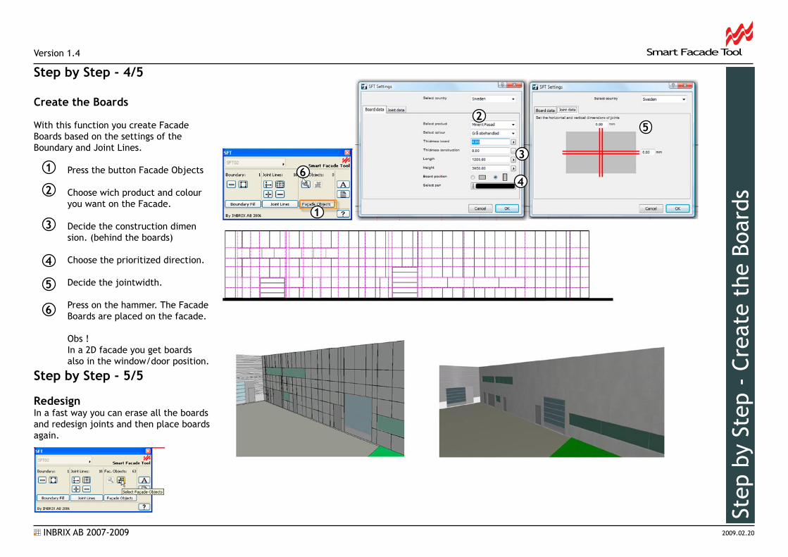
Step by Step - 4/5
Create the Boards
With this function you create Facade Boards based on the settings of the Boundary and Joint Lines.
Press the button Facade Objects
Choose wich product and colour you want on the Facade.
Decide the construction dimen sion. (behind the boards)
Choose the prioritized direction.
Decide the jointwidth.
Press on the hammer. The Facade Boards are placed on the facade.
Obs ! In a 2D facade you get boards also in the window/door position.
Step by Step - 5/5
RedesignIn a fast way you can erase all the boards and redesign joints and then place boards again.
2
3
1
4
2
3
4
Step
by
Step
- C
reat
e th
e Bo
ards1
5
6
5
6
INBRIX AB 2007-2009
Smart Facade ToolVersion 1.4
2009.02.20
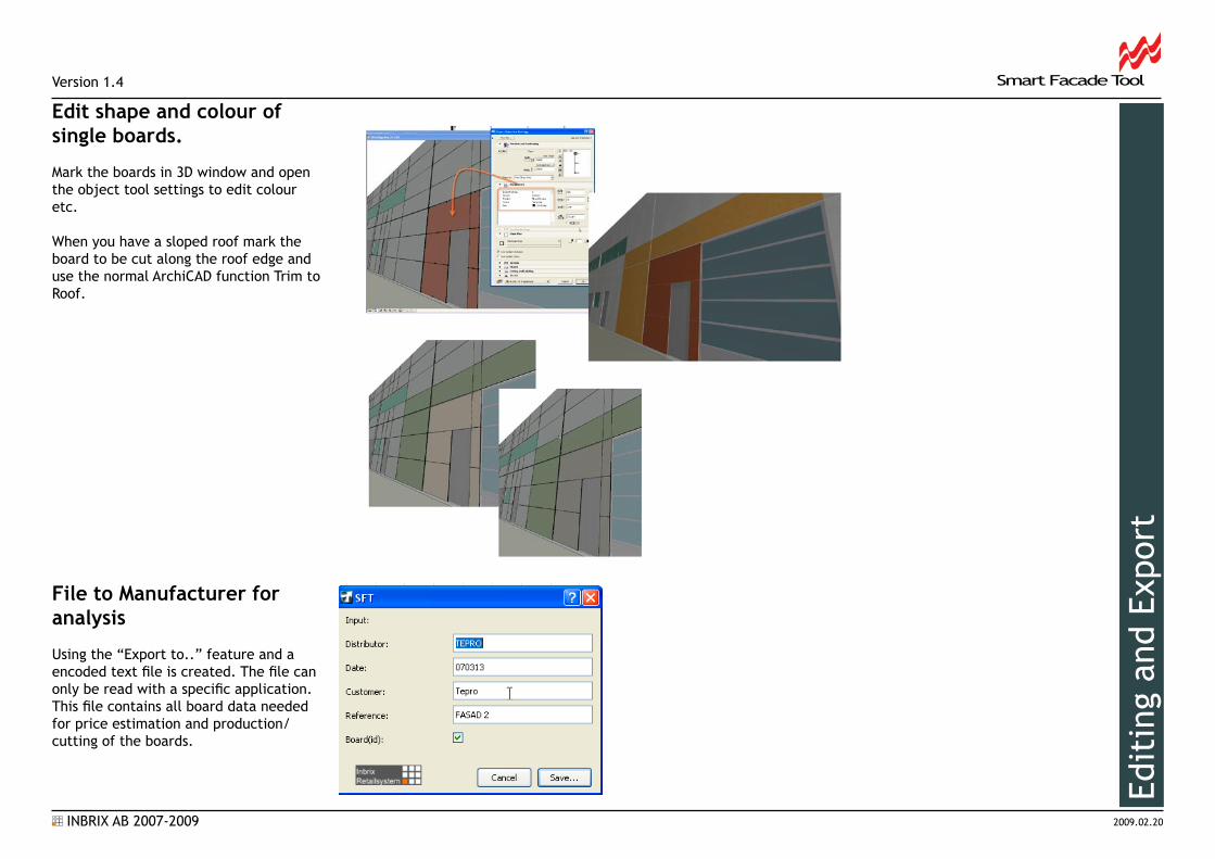
Edit shape and colour of single boards.
Mark the boards in 3D window and open the object tool settings to edit colour etc.
When you have a sloped roof mark the board to be cut along the roof edge and use the normal ArchiCAD function Trim to Roof.
File to Manufacturer for analysis
Using the “Export to..” feature and a encoded text file is created. The file can only be read with a specific application. This file contains all board data needed for price estimation and production/cutting of the boards.
Edit
ing
and
Expo
rt