solutions for factories and industrial plants - hitachi · shown here are shin-etsu (jiangsu)...
TRANSCRIPT

Printed in Japan (H) XX-E343 0513www.hitachi.com/rev
HITACHI REVIEW Carried on the Web
HITACHI REVIEWVolume 62 Number 4 May 2013
Solutions for Factories and Industrial Plants
HITACHI REVIEW
Hitachi Review Vol. 62 (2013), No. 4 236
Along with the growing global demand for social
and industrial infrastructure systems comes the need
to make these systems more advanced. Emerging
economies in particular are experiencing a dramatic
rise in demand for social and industrial infrastructure
against a background of rapid population growth
and economic progress, where social infrastructure
includes water, energy, and large urban developments,
and industrial infrastructure includes industrial estates
and resource development. In Japan, meanwhile,
moves to restructure global supply chains that were
triggered by the great East Japan Earthquake in March
2011 are accelerating, and this in turn is leading to a
rapid expansion in overseas operations by Japanese
companies.
To respond to this global demand for infrastructure
construction, Hitachi is engaged in a wide range of
activities that extend beyond products, systems, and
plant engineering to encompass new social innovation
technologies powered by information technology (IT)
that organically link these elements together.
This issue of Hitachi Review describes how the
different divisions of Hitachi work together to provide
a global, one-stop shop for total solutions that cover:
(1) components based on competitive core products,
(2) engineering, procurement and construction (EPC)
solutions that support plants through every step from
planning and design to construction, and (3) services
that extend across the lifecycle of components and
plants, from maintenance and operation through to
business activities.
With a focus on solutions for factories and
other industrial plants, articles in this issue cover
the establishment of collaborative arrangements
with customers for plant construction, case studies
describing the construction of pharmaceutical and
chemical plants and water treatment systems, example
applications of energy management and energy
efficiency technologies, and the after-sales services
that Hitachi supplies for plants.
I hope that you will find these articles on Hitachi’s
advanced technologies and involvement in social
innovation in the fields of social and industrial
infrastructure to be worthwhile, and that they will
prove useful to your business.
Preface to Solutions for Factories and Industrial Plants
Toshiaki HigashiharaPresident & CEOInfrastructure Systems Group and Infrastructure Systems Company Hitachi, Ltd.
Hitachi Review Vol. 62 (2013), No. 4 237
From Components to Systems—
Supporting Customer’s Global Operations with Solutions for Factories and Industrial Plants
Koji Watanabe, Dr. Eng.
Shigeru Toida
Kazunori Tasaki
Shuichi Hatakama
Toshihiko Horiuchi, Dr. Eng.
CURRENT BUSINESS ENVIRONMENTEMERgIng economies, although also showing signs of slowing growth amid the continuing global economic slowdown, are still expected to maintain their economic development driven by ongoing population growth and investment in social infrastructure. These regions are experiencing vigorous activity in the field of plant construction. These plants are needed to provide the energy, water, transportation and other social infrastructure required for large-scale urban development, and the additional production equipment associated with economic development. Companies see this situation as an opportunity, and are competing fiercely to expand their businesses or enter new markets. To develop their businesses, and with the aims of developing and expanding their markets and reducing costs, these companies are pursuing global operations that include siting production facilities locally and working in partnership with local companies.
Meanwhile, in seeking to establish overseas production facilities, companies face a wide variety of challenges and risks, including regulatory and environmental factors that differ from nation to nation. Examples include the consents required by environmental and other regulations; the optimization of production processes to suit the availability of electric power, transportation, and other local infrastructure; construction planning, which includes the supervision and management of construction contractors; and productivity once the plant is up and running. Dealing with these demands both decision-making based on accurate local knowledge and the ability to act locally.
SOLUTIONS FOR NEEDS OF CORPORATE CUSTOMERS
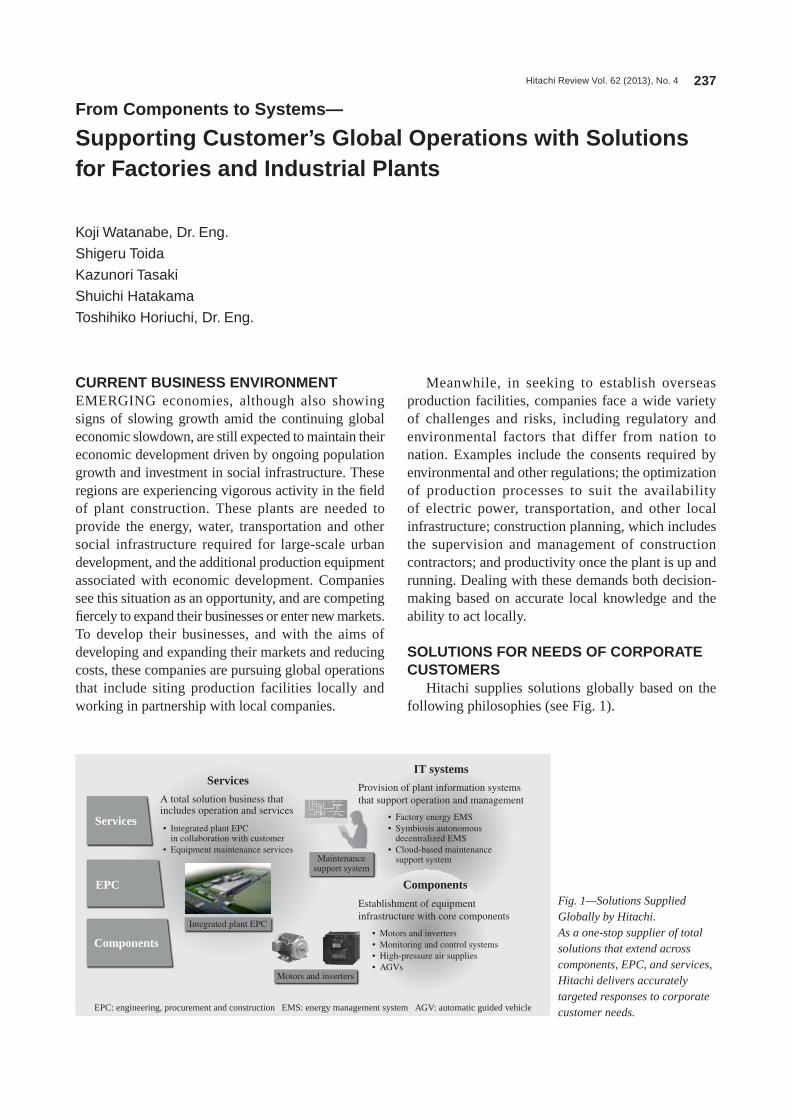
Hitachi supplies solutions globally based on the following philosophies (see Fig. 1).
Services• Integrated plant EPC
in collaboration with customer• Equipment maintenance services
• Factory energy EMS• Symbiosis autonomous
decentralized EMS• Cloud-based maintenance
support system
• Motors and inverters• Monitoring and control systems• High-pressure air supplies• AGVs
Integrated plant EPC
Maintenancesupport system
Motors and inverters
EPC
Components
Services
Components
A total solution business that includes operation and services
IT systems
Provision of plant information systems that support operation and management
Establishment of equipment infrastructure with core components
EPC: engineering, procurement and construction EMS: energy management system AgV: automatic guided vehicle
Fig. 1—Solutions Supplied Globally by Hitachi.As a one-stop supplier of total solutions that extend across components, EPC, and services, Hitachi delivers accurately targeted responses to corporate customer needs.

Hitachi Review Vol. 62 (2013), No. 4 238
(1) An all-encompassing role in the coordination of plant construction, with a capacity for undertaking engineering, procurement, and construction (EPC) projects that involve the execution and management of both planning and construction(2) A capacity to integrate motors, inverters, compressors, and other components required for efficient and reliable production equipment with information technology (IT) systems that support management and operation(3) A capacity for service delivery that can respond quickly and appropriately to the various issues that arise after a plant commences operation
For corporate customers establishing overseas operations and constructing production facilities, Hitachi has the infrastructure to provide full support and deliver solutions that meet their diverse needs, which include ensuring that construction work is conducted in line with the customer’s quality requirements, ensuring that plant commissioning proceeds smoothly, and providing maintenance after the plant commences operation. Hitachi achieves this by utilizing its own overseas operations; by establishing an optimal grouping of construction
partners, contractors, and other vendors from the destination country; and by undertaking global design, procurement, and work management (see Fig. 2).
The following sections describe this approach in more detail using examples.
HITACHI’S INVOLVEMENT IN PLANT CONSTRUCTION AND OPERATION
Plants achieve their purpose through the organic interoperation of multiple components. Hitachi works to maximize value for corporate customers by enhancing this interoperation through the planning, construction, and operational phases.
Plant Construction in Collaboration with Customers
To reduce the risks of overseas plant construction for its corporate customers, Hitachi has established the capabilities to take an all-encompassing approach to projects and to ensure short construction time and high quality. This helps maintain clear communications with customers and an unambiguous division of responsibilities, leaving corporate customers to focus on the planning and operation of their core business,
Hitachi provides centralized management.
Customer’s domestic plants
Planning phase
Technology development
Capital investment by customer
Customer Hitachi
Solution menuEngineering and consulting
Capital investment
New or enhanced products
Rationalization and labor saving
Maintenance and repairs
Increase production capacity.
Global logisticssolutions
Design phase Construction phase Operational phase
Plants for overseas markets,equipment relocation
Coreinvestment
Buildingconstruction
UtilitiesInformation and
productionmanagement
Monitoringand control
Production equipmentMinimization
• Consulting• Support for overseas preliminary
surveys• Survey of environmental regulations
and other legal requirements
• Detailed design• Support for
acquiring consents
• Delivery times, quality management
• Support for plant installation
• Maintenance, ESCO• Energy efficiency
reviews and proposals
Factory dispatch logistics 3PL (sales logistics) Bonded logistics Procurement logistics, joint delivery
Sea and airtransportationPl
anni
ng
Loa
ding
Dra
yage
Cus
tom
scl
eara
nce
(exp
ort)
Impo
rtap
plic
atio
ns
Cus
tom
scl
eara
nce
(im
port
)
Dra
yage
Inst
alla
tion
Dis
asse
mbl
yan
d pa
ckin
g
Unl
oadi
ng a
ndun
pack
ing
Customer siteFrom relocation to local logistics, based on experience and results of Hitachi’s own overseas operations
Fig. 2—Comprehensive Approach to Plant Construction.Hitachi builds optimum plants by fitting the right components together in the right way across the various phases from planning to design, construction, and operation.
ESCo: energy service company 3Pl: 3rd party logistics
Supporting Customer’s Global Operations with Solutions for Factories and Industrial Plants 239
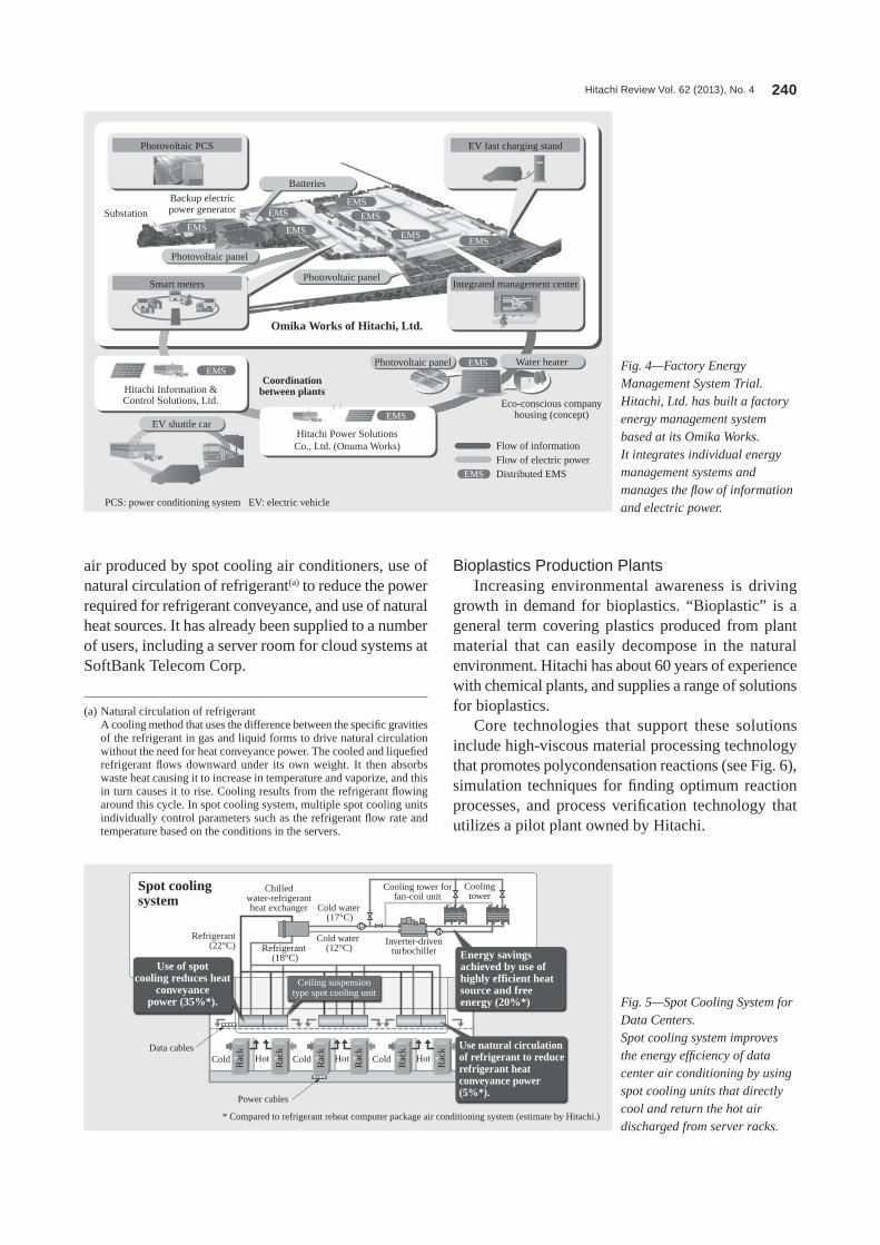
and batteries (4.2 MWh) (see Fig. 4). The first stage includes the use of photovoltaic power generation and batteries in a control system for cutting peak demand, while the plan for the future is for this to develop into a symbiosis autonomous decentralized energy management system (EMS) capable of more sophisticated control in which a number of EMSs work together. Hitachi is also looking to deploy the system at overseas production facilities by customizing it to suit specific local requirements.
CORE HITACHI TECHNOLOGIES USED IN INDUSTRIAL PLANTS
Hitachi has numerous core technologies suitable for use in factories and plants. By combining and applying these distinctive technologies correctly, Hitachi is able to offer solutions capable of further boosting plant productivity. The following sections give some examples of these solutions.
Energy-efficient Air Conditioning System for Data Centers
new data centers are being constructed to keep pace with progress in the information society, including in emerging economies. The increase in heat generation associated with the greater capacity of server hardware means that reducing air conditioning power consumption poses a challenge for the operation of these data centers.
Hitachi has developed the spot cooling system that directly cools the hot air discharged from around server hardware and returns it to the servers as cooling air (see Fig. 5). The benefits of the system include an approximate 60% decrease in the power required for air conditioning. This is achieved through measures such as reducing the heat conveyance power for cool
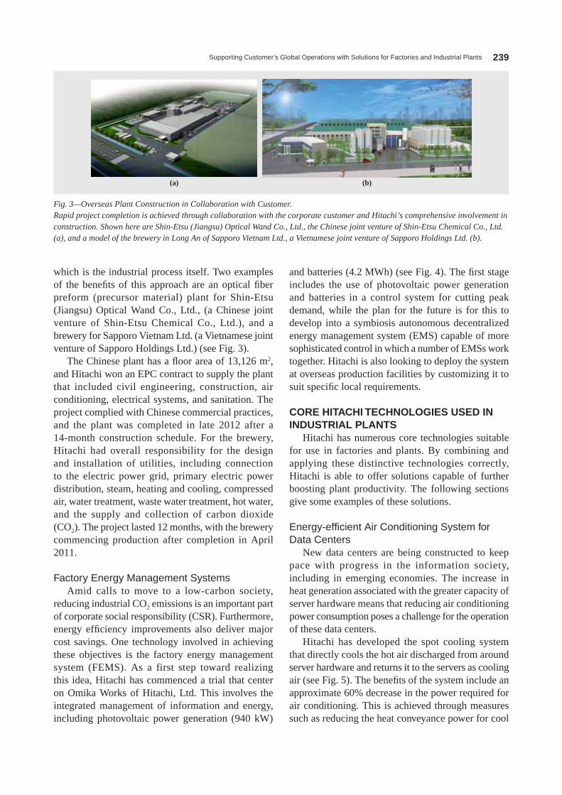
which is the industrial process itself. Two examples of the benefits of this approach are an optical fiber preform (precursor material) plant for Shin-Etsu (Jiangsu) optical Wand Co., ltd., (a Chinese joint venture of Shin-Etsu Chemical Co., ltd.), and a brewery for Sapporo Vietnam ltd. (a Vietnamese joint venture of Sapporo Holdings ltd.) (see Fig. 3).
The Chinese plant has a floor area of 13,126 m2, and Hitachi won an EPC contract to supply the plant that included civil engineering, construction, air conditioning, electrical systems, and sanitation. The project complied with Chinese commercial practices, and the plant was completed in late 2012 after a 14-month construction schedule. For the brewery, Hitachi had overall responsibility for the design and installation of utilities, including connection to the electric power grid, primary electric power distribution, steam, heating and cooling, compressed air, water treatment, waste water treatment, hot water, and the supply and collection of carbon dioxide (Co2). The project lasted 12 months, with the brewery commencing production after completion in April 2011.
Factory Energy Management SystemsAmid calls to move to a low-carbon society,
reducing industrial Co2 emissions is an important part of corporate social responsibility (CSR). Furthermore, energy efficiency improvements also deliver major cost savings. one technology involved in achieving these objectives is the factory energy management system (FEMS). As a first step toward realizing this idea, Hitachi has commenced a trial that center on omika Works of Hitachi, ltd. This involves the integrated management of information and energy, including photovoltaic power generation (940 kW)
(a) (b)
Fig. 3—Overseas Plant Construction in Collaboration with Customer.Rapid project completion is achieved through collaboration with the corporate customer and Hitachi’s comprehensive involvement in construction. Shown here are Shin-Etsu (Jiangsu) Optical Wand Co., Ltd., the Chinese joint venture of Shin-Etsu Chemical Co., Ltd. (a), and a model of the brewery in Long An of Sapporo Vietnam Ltd., a Vietnamese joint venture of Sapporo Holdings Ltd. (b).
Hitachi Review Vol. 62 (2013), No. 4 240
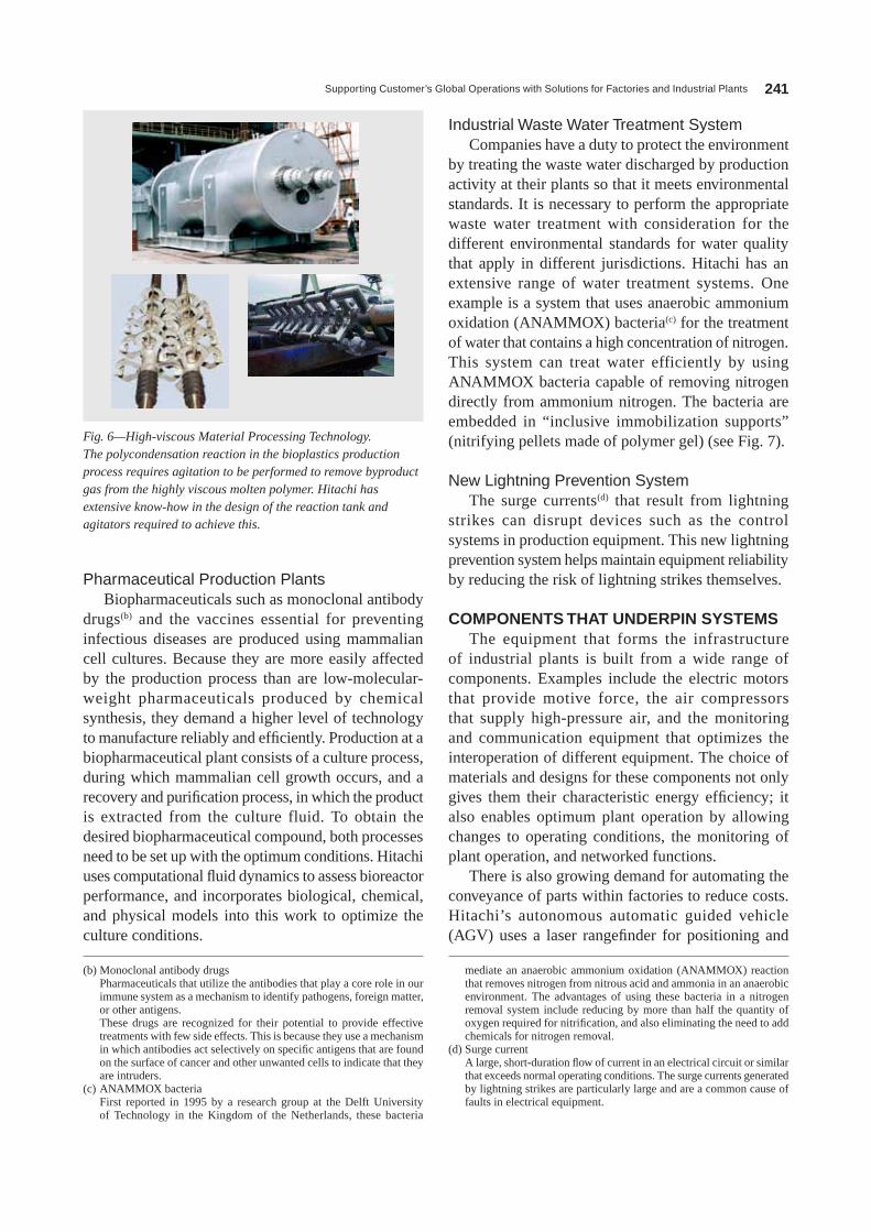
Bioplastics Production PlantsIncreasing environmental awareness is driving
growth in demand for bioplastics. “Bioplastic” is a general term covering plastics produced from plant material that can easily decompose in the natural environment. Hitachi has about 60 years of experience with chemical plants, and supplies a range of solutions for bioplastics.
Core technologies that support these solutions include high-viscous material processing technology that promotes polycondensation reactions (see Fig. 6), simulation techniques for finding optimum reaction processes, and process verification technology that utilizes a pilot plant owned by Hitachi.
air produced by spot cooling air conditioners, use of natural circulation of refrigerant(a) to reduce the power required for refrigerant conveyance, and use of natural heat sources. It has already been supplied to a number of users, including a server room for cloud systems at SoftBank Telecom Corp.
Photovoltaic PCS EV fast charging stand
Photovoltaic panel
EV shuttle car
EMSEMS
EMS
EMS
EMS
EMS
EMS
EMS
EMS
EMS
EMS
Photovoltaic panel
Substation
Hitachi Information &Control Solutions, Ltd.
Coordinationbetween plants
Omika Works of Hitachi, Ltd.
Eco-conscious companyhousing (concept)
Flow of informationFlow of electric powerDistributed EMS
Hitachi Power SolutionsCo., Ltd. (Onuma Works)
Batteries
Photovoltaic panel Water heater
Backup electricpower generator
Integrated management centerSmart meters
1234 1234
1234
PCS: power conditioning system EV: electric vehicle
Fig. 4—Factory Energy Management System Trial.Hitachi, Ltd. has built a factory energy management system based at its Omika Works. It integrates individual energy management systems and manages the flow of information and electric power.
Chilledwater-refrigerantheat exchanger
Cooling tower forfan-coil unit
Inverter-driventurbochiller
Coolingtower
Cold water (17°C)
Cold water (12°C)
Refrigerant (22°C) Refrigerant
(18°C)
Data cablesCold
Rac
k
Rac
k
Rac
k
Rac
k
Rac
k
Rac
k
Cold ColdHot Hot Hot
Power cables
* Compared to refrigerant reheat computer package air conditioning system (estimate by Hitachi.)
Spot cooling system
Use of spotcooling reduces heat
conveyancepower (35%*).
Energy savingsachieved by use ofhighly efficient heat source and free energy (20%*)
Use natural circulationof refrigerant to reducerefrigerant heatconveyance power(5%*).
Ceiling suspensiontype spot cooling unit
Fig. 5—Spot Cooling System for Data Centers.Spot cooling system improves the energy efficiency of data center air conditioning by using spot cooling units that directly cool and return the hot air discharged from server racks.
(a) natural circulation of refrigerant A cooling method that uses the difference between the specific gravities
of the refrigerant in gas and liquid forms to drive natural circulation without the need for heat conveyance power. The cooled and liquefied refrigerant flows downward under its own weight. It then absorbs waste heat causing it to increase in temperature and vaporize, and this in turn causes it to rise. Cooling results from the refrigerant flowing around this cycle. In spot cooling system, multiple spot cooling units individually control parameters such as the refrigerant flow rate and temperature based on the conditions in the servers.
Supporting Customer’s Global Operations with Solutions for Factories and Industrial Plants 241
Industrial Waste Water Treatment SystemCompanies have a duty to protect the environment
by treating the waste water discharged by production activity at their plants so that it meets environmental standards. It is necessary to perform the appropriate waste water treatment with consideration for the different environmental standards for water quality that apply in different jurisdictions. Hitachi has an extensive range of water treatment systems. one example is a system that uses anaerobic ammonium oxidation (AnAMMoX) bacteria(c) for the treatment of water that contains a high concentration of nitrogen. This system can treat water efficiently by using AnAMMoX bacteria capable of removing nitrogen directly from ammonium nitrogen. The bacteria are embedded in “inclusive immobilization supports” (nitrifying pellets made of polymer gel) (see Fig. 7).
New Lightning Prevention SystemThe surge currents(d) that result from lightning
strikes can disrupt devices such as the control systems in production equipment. This new lightning prevention system helps maintain equipment reliability by reducing the risk of lightning strikes themselves.
COMPONENTS THAT UNDERPIN SYSTEMSThe equipment that forms the infrastructure
of industrial plants is built from a wide range of components. Examples include the electric motors that provide motive force, the air compressors that supply high-pressure air, and the monitoring and communication equipment that optimizes the interoperation of different equipment. The choice of materials and designs for these components not only gives them their characteristic energy efficiency; it also enables optimum plant operation by allowing changes to operating conditions, the monitoring of plant operation, and networked functions.
There is also growing demand for automating the conveyance of parts within factories to reduce costs. Hitachi’s autonomous automatic guided vehicle (AgV) uses a laser rangefinder for positioning and
Pharmaceutical Production PlantsBiopharmaceuticals such as monoclonal antibody
drugs(b) and the vaccines essential for preventing infectious diseases are produced using mammalian cell cultures. Because they are more easily affected by the production process than are low-molecular-weight pharmaceuticals produced by chemical synthesis, they demand a higher level of technology to manufacture reliably and efficiently. Production at a biopharmaceutical plant consists of a culture process, during which mammalian cell growth occurs, and a recovery and purification process, in which the product is extracted from the culture fluid. To obtain the desired biopharmaceutical compound, both processes need to be set up with the optimum conditions. Hitachi uses computational fluid dynamics to assess bioreactor performance, and incorporates biological, chemical, and physical models into this work to optimize the culture conditions.
(b) Monoclonal antibody drugs Pharmaceuticals that utilize the antibodies that play a core role in our
immune system as a mechanism to identify pathogens, foreign matter, or other antigens.
These drugs are recognized for their potential to provide effective treatments with few side effects. This is because they use a mechanism in which antibodies act selectively on specific antigens that are found on the surface of cancer and other unwanted cells to indicate that they are intruders.
(c) AnAMMoX bacteria First reported in 1995 by a research group at the Delft University
of Technology in the Kingdom of the netherlands, these bacteria
mediate an anaerobic ammonium oxidation (AnAMMoX) reaction that removes nitrogen from nitrous acid and ammonia in an anaerobic environment. The advantages of using these bacteria in a nitrogen removal system include reducing by more than half the quantity of oxygen required for nitrification, and also eliminating the need to add chemicals for nitrogen removal.
(d) Surge current A large, short-duration flow of current in an electrical circuit or similar
that exceeds normal operating conditions. The surge currents generated by lightning strikes are particularly large and are a common cause of faults in electrical equipment.
Fig. 6—High-viscous Material Processing Technology.The polycondensation reaction in the bioplastics production process requires agitation to be performed to remove byproduct gas from the highly viscous molten polymer. Hitachi has extensive know-how in the design of the reaction tank and agitators required to achieve this.

Hitachi Review Vol. 62 (2013), No. 4 242
solutions for maintenance after the equipment commences operation.
In emerging economies, factors such as traffic congestion make it difficult to provide effective inspection services in the form of on-site “patrol” inspections in which maintenance personnel make regular visits to each production site to conduct inspections and perform repairs or adjustments as needed. Hitachi has developed and started to deploy technology for supporting cloud-based maintenance services in order to improve further the level of equipment maintenance supplied to corporate customers.
In addition to monitoring the operation of machinery and other equipment so that the resulting information can be stored and processed at the data
localization algorithm. Because it does not require the installation of guide lines, and because of the ease with which it can adapt to changes in plant layout, the autonomous AgV is highly regarded for its wide range of potential applications.
EQUIPMENT MAINTENANCE SERVICESEquipment maintenance has an essential role in
ensuring that production at industrial plants proceeds smoothly. While maintenance frequently requires specialist knowledge and experience, obtaining appropriate maintenance personnel is often difficult due to a shortage of such people or because they lack these attributes. The scope of services provided by Hitachi extends beyond just the construction of plants and the supply of equipment; it also encompasses
Internet User A data
User B data
Advanced functions
User A
Data center
User B
Webapplication
Webapplication
Timely on-site visits
Merge
Advanced diagnosticsby expert
Control center
User Amaintenance plan
User Bmaintenance plan
Benefits of installation
Cloud services
Equipment
Diagnostic software (cloud-based)
Advanced diagnostics(predictive diagnostics)
Alarm monitoringPreparation of proposals
Diagnostic tools Diagnostic analysis Service improvement
Equipment
User benefits • Reduce initial cost of installation. • Reassurance of monitoring by supplierSupplier benefits • Sharing of information with users • Collection of operational data
Fig. 8—Cloud-based Maintenance Services.By monitoring the operation of machinery and other equipment and then storing and processing the resulting information at a data center, the system enables not only emergency response, but also activities such as the formulation of precise maintenance plans that allow optimum operation. The anticipated benefits include reducing the total cost of maintenance, improving utilization, and ensuring safe operation.
3 mm
Rawwater
PollutantsNitrifying pellets
Nitrifying pellets
Separator
Treatedwater
Biological reaction tank
Polymer aqueous gel
Microorganisms (nitrifying bacteria)
Fig. 7—Comprehensive Immobilizing Nitrogen Removal System.The system can treat water efficiently by using microorganisms capable of breaking down ammonium nitrogen that are embedded in nitrifying pellets (inclusive immobilization supports made of polymer gel).
Supporting Customer’s Global Operations with Solutions for Factories and Industrial Plants 243
In the future, Hitachi intends to utilize its strengths in core technologies and components to supply plant information systems that support operation and management, while also drawing on its engineering capabilities to support global business operations with solutions that package together elements ranging from components and systems to operations and services. Hitachi also intends to extend its range of component products that deliver greater reliability, faster speeds, and increased capacity in the systems that support these activities, and also to continue enhancing its “top runner” products that enable energy and resource efficiency.
center, this technology also facilitates tasks such as the automated generation of maintenance plans, spare parts administration, and emergency response (see Fig. 8). The anticipated benefits include reducing the total cost of maintenance and cutting downtime.
FUTURE ACTIVITIESAs described in this article, Hitachi has been
supporting its corporate customers by utilizing its engineering capabilities, which are underpinned by extensive experience, to bring together distinctive systems and components and supply comprehensive construction solutions designed to suit local conditions.
Shigeru ToidaJoined Hitachi, Ltd. in 1978, and now works at the Solution Service Promotion Office, Strategic Planning Division, Infrastructure Systems Company. He is currently engaged in planning for service business magnification. Mr. Toida is a member of The Japan Society of Mechanical Engineers.
Shuichi HatakamaJoined Hitachi, Ltd. in 2010, and now works at the Civil & Architectural Design Department, Engineering Division, Infrastructure Construction & Engineering Division, Infrastructure Systems Company. He is APEC Engineer (structural), APEC
Architect, and 1st-class Kenchikushi IntPE (JP), and currently engaged in planning of factory and industrial infrastructure. Mr. Hatakama is a member of the Architectural Institute of Japan and the Tokyo Society of Architects & Building Engineers.
Koji Watanabe, Dr. Eng.Joined Hitachi Plant Engineering & Construction Co., Ltd. in 1979, and now works at the Technology Management Division, Hitachi Plant Services Co., Ltd. He is currently engaged in the planning of company business and service strategies. Dr. Watanabe is a member of the Japan Society of Refrigerating and Air Conditioning Engineers and The Association of Powder Process Industry and Engineering, Japan.
Kazunori TasakiJoined Hitachi Engineering Co., Ltd. in 1978, and now works at the Industrial Infrastructure Engineering Department, Engineering Division, Social Infrastructure & Industrial Plant Systems Business Management Division, Infrastructure Systems
Company, Hitachi, Ltd. He is currently engaged in the planning of industrial infrastructure.
Toshihiko Horiuchi, Dr. Eng.Joined Hitachi, Ltd. in 1984, and now works at the Middle East Regional Headquarters, Infrastructural Systems Group. He is currently engaged in the management of research and development operation and the development of new business. Dr. Horiuchi is a member of The Japan Society of Mechanical Engineers and the Japan Association for Earthquake Engineering.
ABOUT THE AUTHORS

Hitachi Review Vol. 62 (2013), No. 4 244
Turnkey Construction of Factories in Asia
Yoshihiro Kimoto
Jin Qi Chang
Takumi Sugiura
OVERVIEW: An increasing number of companies are seeking to operate multiple production sites, and many are choosing sites in the ASEAN and other nations of the Asian Belt Zone*. However, this poses numerous challenges, including the collection of local information and differences in culture, business practices, laws, and legal systems. In particular, many companies considering the construction of new plants are looking to resolve problems in a variety of fields, especially those that relate to know-how and conformance with local requirements. Based on its extensive past experience, Hitachi is able to supply integrated solutions for industry that extend from plant construction through to things like air conditioning, utilities, and waste water treatment, and that take account of local customs and the relevant planning and legal systems.
INTRODUCTIONAS globalization proceeds, corporate interest in establishing offshore operations is growing. In addition to the necessity of conducting the various planning, design, procurement, and construction stages of an overseas factory construction project in accordance with local laws and work practices, such projects are also characterized by the need to deal with many different overseas companies. Corporate interest in operating multiple production sites is currently running very high, with many companies choosing to focus their international operations in Southeast Asia.
Japanese companies, for example, see about 30% of the barriers and challenges associated with overseas operations coming from differences in culture and business practices and differences in legal systems, and about 20% coming from the difficulty of collecting local information(1). Companies are looking to resolve problems in a variety of fields, especially those that relate to know-how and conformance with local requirements.
Hitachi builds industrial plants, such as clean rooms and factories for pharmaceuticals, food, and chemicals, with a track record of operations in the Republic of Singapore and other parts of Asia in particular that dates back more than 30 years (see Fig. 1). Based on this extensive experience, the company is able to supply Asia and the rest of the world with integrated solutions for industrial plants
that extend from construction through to things like air conditioning, utilities, and waste water treatment.
This article discusses the challenges facing the establishment of overseas operations and describes examples of relevant solutions.
CHALLENGES AND SOLUTIONS FOR OVERSEAS PLANT CONSTRUCTION
Companies seeking to establish operations in foreign countries often face a range of concerns that extend from basic planning through to construction and maintenance, including planning, site selection, standards and other destination country rules, application procedures, assessment of suppliers, and plant maintenance management (see Fig. 2).
* The coastal region of Asia extending from Japan to the Arabian Peninsula, encompassing 24 nations or territories, including China, the Association of Southeast Asian nations (ASEAn), India, and the Middle East.
Number of operations worldwide
Japan 40Asia (excluding Japan) 24Middle East and Africa 7
Europe 1Oceania 1Central and South America
As of September 2012
1
Fig. 1—Overseas Operations of Hitachi.Hitachi has operations at 24 sites in Asia to support the construction of plants.
Turnkey Construction of Factories in Asia 245
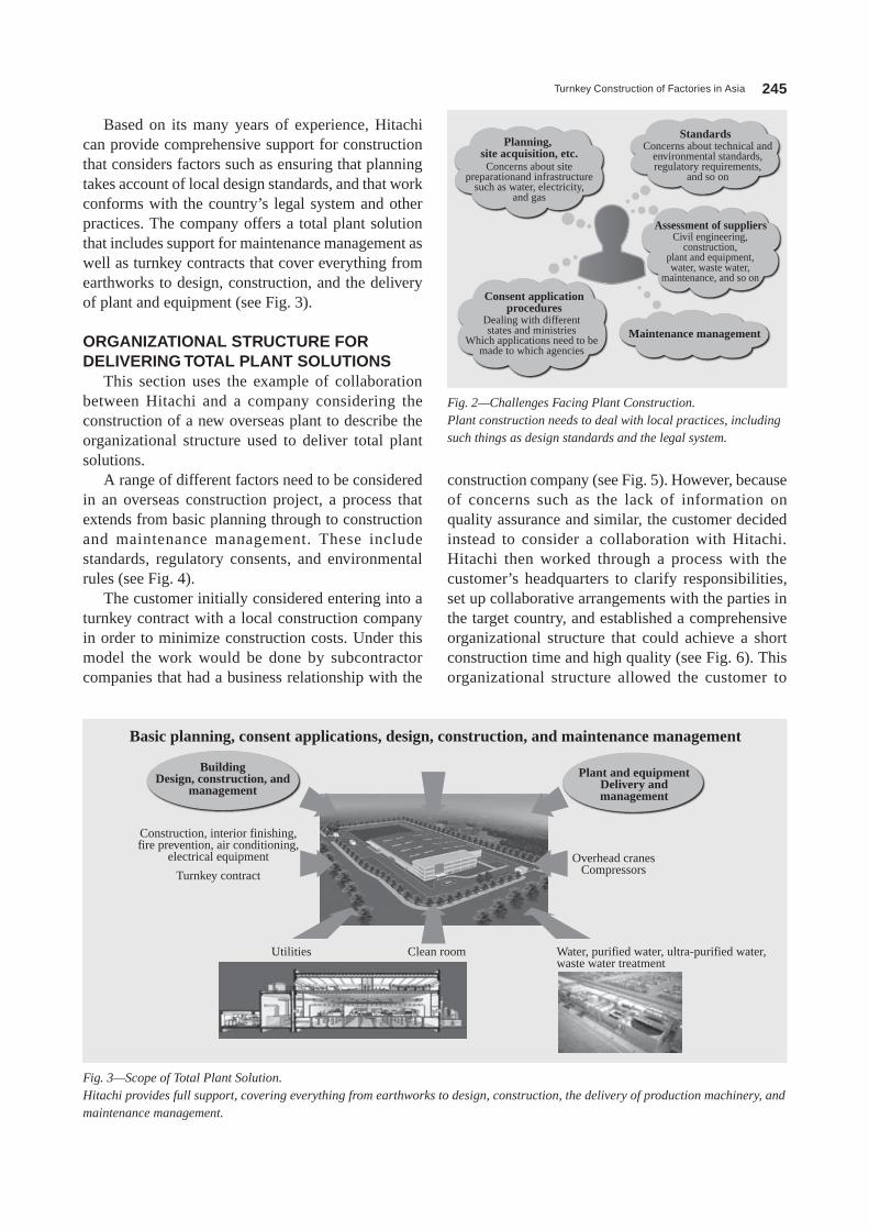
Based on its many years of experience, Hitachi can provide comprehensive support for construction that considers factors such as ensuring that planning takes account of local design standards, and that work conforms with the country’s legal system and other practices. The company offers a total plant solution that includes support for maintenance management as well as turnkey contracts that cover everything from earthworks to design, construction, and the delivery of plant and equipment (see Fig. 3).
ORGANIZATIONAL STRUCTURE FOR DELIVERING TOTAL PLANT SOLUTIONS
This section uses the example of collaboration between Hitachi and a company considering the construction of a new overseas plant to describe the organizational structure used to deliver total plant solutions.
A range of different factors need to be considered in an overseas construction project, a process that extends from basic planning through to construction and maintenance management. These include standards, regulatory consents, and environmental rules (see Fig. 4).
The customer initially considered entering into a turnkey contract with a local construction company in order to minimize construction costs. Under this model the work would be done by subcontractor companies that had a business relationship with the
construction company (see Fig. 5). However, because of concerns such as the lack of information on quality assurance and similar, the customer decided instead to consider a collaboration with Hitachi. Hitachi then worked through a process with the customer’s headquarters to clarify responsibilities, set up collaborative arrangements with the parties in the target country, and established a comprehensive organizational structure that could achieve a short construction time and high quality (see Fig. 6). This organizational structure allowed the customer to
Concerns about sitepreparationand infrastructure
such as water, electricity,and gas
Planning, site acquisition, etc.
Concerns about technical andenvironmental standards,regulatory requirements,
and so on
Standards
Civil engineering,construction,
plant and equipment,water, waste water,
maintenance, and so on
Assessment of suppliers
Maintenance managementDealing with differentstates and ministries
Which applications need to bemade to which agencies
Consent applicationprocedures
Fig. 2—Challenges Facing Plant Construction.Plant construction needs to deal with local practices, including such things as design standards and the legal system.
Basic planning, consent applications, design, construction, and maintenance management
BuildingDesign, construction, and
management
Construction, interior finishing,fire prevention, air conditioning,
electrical equipment Overhead cranesCompressors
Utilities Clean room Water, purified water, ultra-purified water,waste water treatment
Turnkey contract
Plant and equipmentDelivery andmanagement
Fig. 3—Scope of Total Plant Solution.Hitachi provides full support, covering everything from earthworks to design, construction, the delivery of production machinery, and maintenance management.

Hitachi Review Vol. 62 (2013), No. 4 246
Customer (subsidiary)
Responsible for basic andconstruction design
Detailed design Work supervision
Local construction company
Construction subcontractors
Construction Civilengineering work
Interiorfinishing
Airconditioning
Sanitaryplumbing
Electricalwork
Plant and equipment subcontractors
Construction designSelection of construction companySupervision and technical guidance
Assign workersregardless of specialty.
Construction design company(design office)
Fig. 5—Organizational Structure Based on Use of Local Companies.This example is based on issuing a turnkey contract to a local construction company.
Basic planning
Company formation
Site acquisition
Design and environmental assessment
Construction consent
Construction work
Inspection by government agencies
Equipment delivery
Official plant operation
Maintenance management
Considerations
Design conforms tolocal standards.
Lack of capacity atlocal design office
Numerous and complexregulatory consents
Strict environmental rulesImportance of assessments
Ambiguous division of responsibilitybetween different suppliers
Quality assurance capabilitiesof local companies
Responses
• Convert Japanese designto local standards.
• Have checks performedby experienced designer.
• Appropriate actionsbased on extensiveexperience
• Turnkey supply ofwater treatment
• Responsible designand work based onsingle organization
Fig. 4—Key Considerations for Overseas Plant Construction.A range of factors need to be considered when constructing a plant overseas, a process that extends from basic planning to maintenance management.
Customer (headquarters) Customer (subsidiary)Planning, design,procurement
Procurement, construction,commissioning
Project management, engineering planning, design, electrical procurement(for some equipment) Procurement of
Hitachi equipment
Construction and ancillaryequipment design
Construction, ancillary equipment, electrical equipment, utilities (process machinery, ancillary equipment)
Regulatory consentsConstruction andancillary equipmentElectric powerUtilities(process machinery,ancillary equipment)
Local Hitachi subsidiary
Preparation of work drawings(construction, ancillary equipment, electric power, utilities)
Design office (basic design)
Hitachi, Ltd.
Suppliers
Infrastructure Construction & Engineering Division
Hitachi Architects & Engineers Co., Ltd.Hitachi Transport System, Ltd., others
Design, procurement ofengineering equipment,SV deployment
Construction design and workSelection of contractors, supervision of work Equipment procurement, installation, and commissioning
Coordination
Hitachi
Target country
Fig. 6—Collaborative Arrangement with Parties in Target Country.Clear communications and an unambiguous division of responsibilities can be achieved by establishing a collaborative arrangement between the customer and Hitachi.SV: Supervisor
Turnkey Construction of Factories in Asia 247
the various levels of local government to successfully complete the project in accordance with the basic plan of Shin-Etsu Chemical Co., ltd. This included an emphasis on use of products sourced in China, with differences between Japanese and Chinese specifications being dealt with as necessary (see Fig. 8 and Fig. 9).
Turnkey Contract for Supply of Utilities to BreweryOverview
Sapporo Vietnam ltd. is a beer production and marketing company that was jointly established by Sapporo Holdings ltd. and Vietnam national Tobacco Corporation. Sapporo Vietnam’s new brewery in long An plans to step up production progressively until it reaches 150,000 kl in 2019. This is the first time a Japanese brewer has established operations in the Socialist Republic of Viet nam. The brewery
focus on their core business, which was the industrial process itself.
CASE STUDIESTurnkey Supply of Optical Materials Plant in ChinaOverview
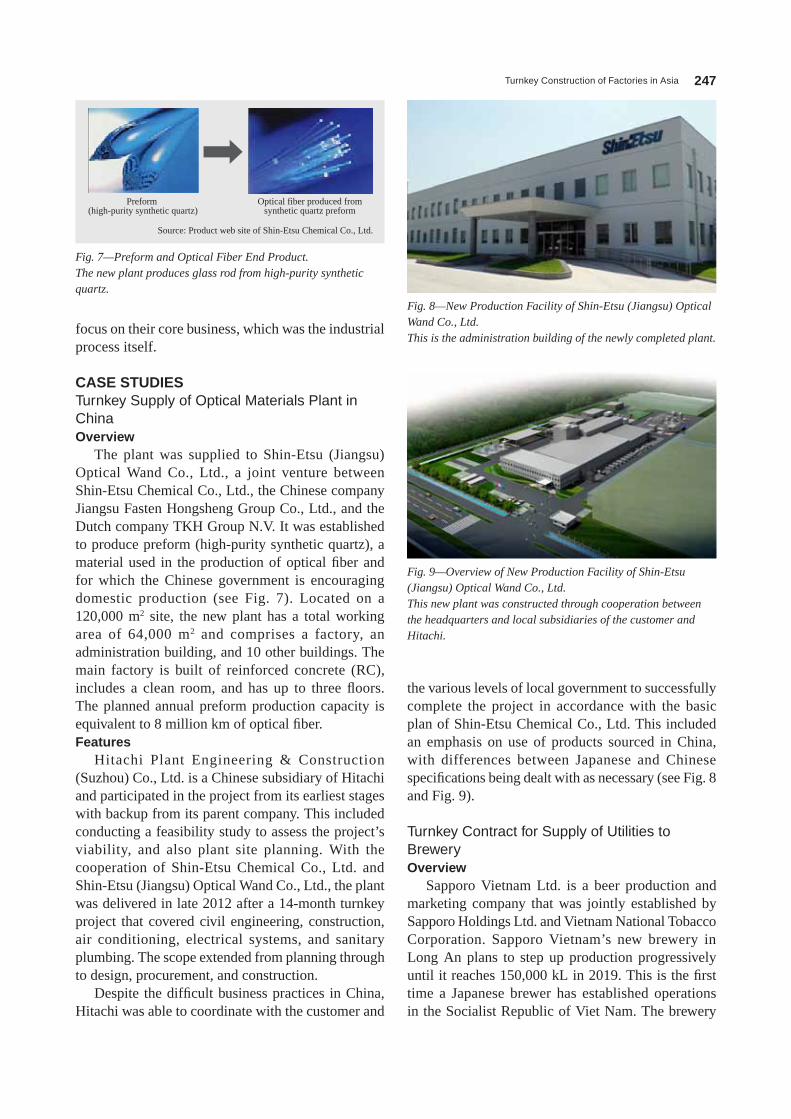
The plant was supplied to Shin-Etsu (Jiangsu) optical Wand Co., ltd., a joint venture between Shin-Etsu Chemical Co., ltd., the Chinese company Jiangsu Fasten Hongsheng group Co., ltd., and the Dutch company TKH group n.V. It was established to produce preform (high-purity synthetic quartz), a material used in the production of optical fiber and for which the Chinese government is encouraging domestic production (see Fig. 7). located on a 120,000 m2 site, the new plant has a total working area of 64,000 m2 and comprises a factory, an administration building, and 10 other buildings. The main factory is built of reinforced concrete (RC), includes a clean room, and has up to three floors. The planned annual preform production capacity is equivalent to 8 million km of optical fiber.Features
Hitachi Plant Engineering & Construction (Suzhou) Co., ltd. is a Chinese subsidiary of Hitachi and participated in the project from its earliest stages with backup from its parent company. This included conducting a feasibility study to assess the project’s viability, and also plant site planning. With the cooperation of Shin-Etsu Chemical Co., ltd. and Shin-Etsu (Jiangsu) optical Wand Co., ltd., the plant was delivered in late 2012 after a 14-month turnkey project that covered civil engineering, construction, air conditioning, electrical systems, and sanitary plumbing. The scope extended from planning through to design, procurement, and construction.
Despite the difficult business practices in China, Hitachi was able to coordinate with the customer and
Fig. 7—Preform and Optical Fiber End Product.The new plant produces glass rod from high-purity synthetic quartz.
Preform (high-purity synthetic quartz)
Source: Product web site of Shin-Etsu Chemical Co., Ltd.
Optical fiber produced fromsynthetic quartz preform
Fig. 8—New Production Facility of Shin-Etsu (Jiangsu) Optical Wand Co., Ltd.This is the administration building of the newly completed plant.
Fig. 9—Overview of New Production Facility of Shin-Etsu (Jiangsu) Optical Wand Co., Ltd.This new plant was constructed through cooperation between the headquarters and local subsidiaries of the customer and Hitachi.
Hitachi Review Vol. 62 (2013), No. 4 248
Japan and its experience in Vietnam. The supplied equipment plays important roles throughout the beer production process, including grid interconnection equipment, primary electric power distribution, steam, heating and cooling, compressed air, water treatment, waste water treatment, hot water, supply and collection of carbon dioxide, and a chemical dispensing system. In undertaking this construction project, Hitachi focused on the following points in particular.(1) Construction of plant to same standard as in Japan or Europe
Assessment of performance and quality of locally sourced products(2) Compliance with local environmental rules, laws, and standards
Familiarity with Vietnamese laws and standards(3) Comprehensive construction quality management
A thorough approach to training local workers and managing construction quality(4) Work management system designed for short construction schedule
A thorough approach to project management and establishment of work management systems able to cope with tight schedules
Work started on the plant in July 2010 and completed in november 2011, making it the first Japanese brewery to be built in Vietnam. The brewery has an annual production capacity of 40,000 kl.
CONCLUSIONSThis article has discussed the challenges facing the
establishment of overseas operations and described examples of relevant Hitachi solutions.
The construction of overseas plants requires an organizational structure that is capable of performing design, construction, and maintenance management based on an understanding of the laws, standards, and
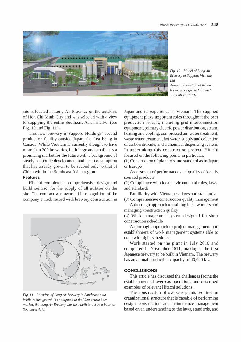
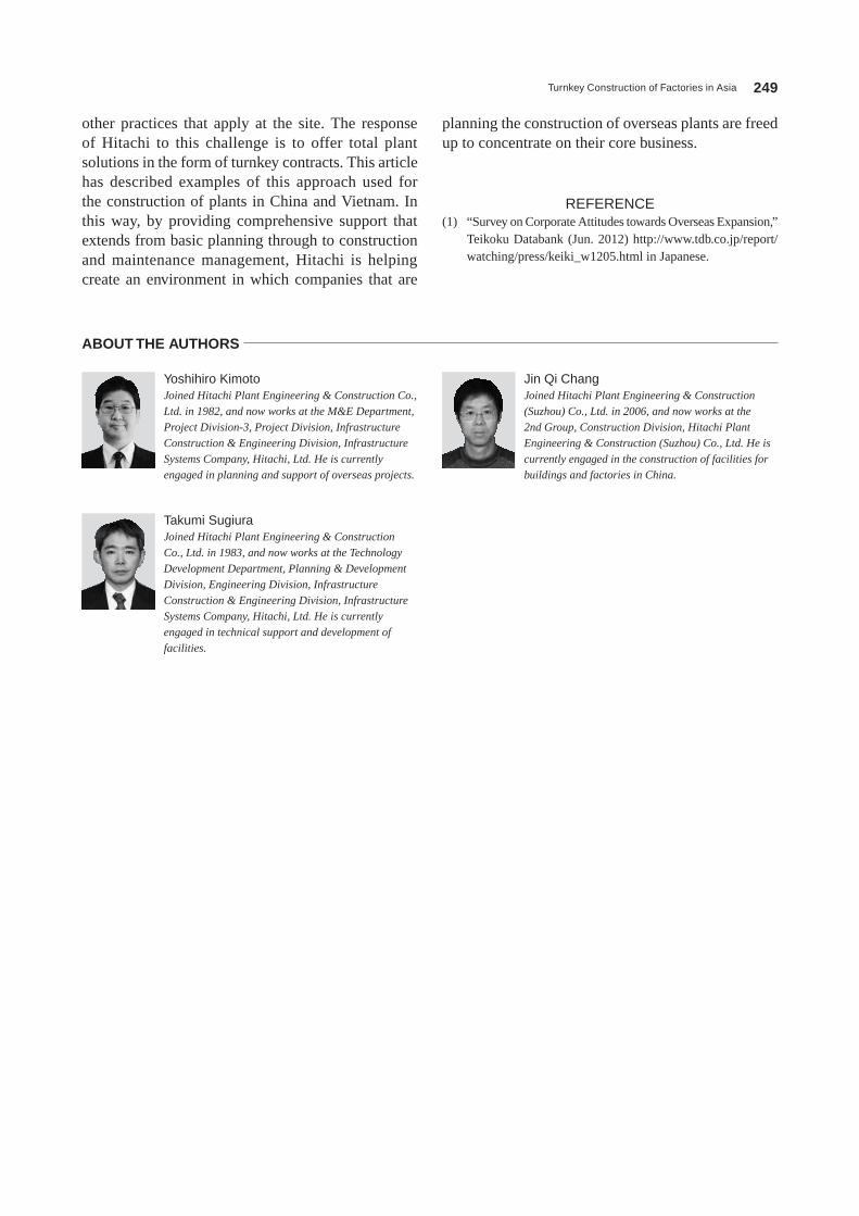
site is located in long An Province on the outskirts of Hoh Chi Minh City and was selected with a view to supplying the entire Southeast Asian market (see Fig. 10 and Fig. 11).
This new brewery is Sapporo Holdings’ second production facility outside Japan, the first being in Canada. While Vietnam is currently thought to have more than 300 breweries, both large and small, it is a promising market for the future with a background of steady economic development and beer consumption that has already grown to be second only to that of China within the Southeast Asian region.Features
Hitachi completed a comprehensive design and build contract for the supply of all utilities on the site. The contract was awarded in recognition of the company’s track record with brewery construction in
Fig. 10—Model of Long An Brewery of Sapporo Vietnam Ltd.Annual production at the new brewery is expected to reach 150,000 kL in 2019.
Fig. 11—Location of Long An Brewery in Southeast Asia.While robust growth is anticipated in the Vietnamese beer market, the Long An Brewery was also built to act as a base for Southeast Asia.
Turnkey Construction of Factories in Asia 249
planning the construction of overseas plants are freed up to concentrate on their core business.
REFERENCE(1) “Survey on Corporate Attitudes towards overseas Expansion,”
Teikoku Databank (Jun. 2012) http://www.tdb.co.jp/report/watching/press/keiki_w1205.html in Japanese.
other practices that apply at the site. The response of Hitachi to this challenge is to offer total plant solutions in the form of turnkey contracts. This article has described examples of this approach used for the construction of plants in China and Vietnam. In this way, by providing comprehensive support that extends from basic planning through to construction and maintenance management, Hitachi is helping create an environment in which companies that are
Jin Qi ChangJoined Hitachi Plant Engineering & Construction (Suzhou) Co., Ltd. in 2006, and now works at the 2nd Group, Construction Division, Hitachi Plant Engineering & Construction (Suzhou) Co., Ltd. He is currently engaged in the construction of facilities for buildings and factories in China.
Yoshihiro KimotoJoined Hitachi Plant Engineering & Construction Co., Ltd. in 1982, and now works at the M&E Department, Project Division-3, Project Division, Infrastructure Construction & Engineering Division, Infrastructure Systems Company, Hitachi, Ltd. He is currently engaged in planning and support of overseas projects.
Takumi SugiuraJoined Hitachi Plant Engineering & Construction Co., Ltd. in 1983, and now works at the Technology Development Department, Planning & Development Division, Engineering Division, Infrastructure Construction & Engineering Division, Infrastructure Systems Company, Hitachi, Ltd. He is currently engaged in technical support and development of facilities.
ABOUT THE AUTHORS
Hitachi Review Vol. 62 (2013), No. 4 250
Factory and Community Energy-saving System Solutions for Low-carbon Society
Takaki Taniguchi OVERVIEW: As society moves towards a low-carbon future, the adoption of renewable energy and the utilization of previously untapped energy sources have grown in importance along with ongoing improvements in energy efficiency at manufacturing plants. Meanwhile, compliance with host country regulations and coordination with the local community are also important factors for plant construction. Hitachi supplies factory and community energy-saving system solutions for a low-carbon society.
INTRODUCTIONAS global carbon dioxide (Co2) emissions continue to increase, energy saving technologies have become increasingly important as momentum gathers for the shift to a low-carbon society based around emissions reduction measures.
Increasingly, manufacturing plants that consume large amounts of energy are adopting renewable energy, utilizing previously untapped energy sources (such as energy from plant waste heat or temperature differences), and installing distributed power supplies (such as gas cogeneration and fuel cells). Also, amid moves to save energy, energy service company (ESCo) businesses are making a major contribution to improving energy efficiency in the industrial and commercial sectors. Meanwhile a newly emerging requirement is to take account of the environment in which manufacturing plants operate, including business continuity planning (BCP) and integrating operations with neighboring communities.
In the case of new plant construction and the practice of operating multiple production sites, important factors include creating a low-carbon society, compliance with energy regulations in the host country, and integration into the communities in which the plants are located.
This article provides examples of energy-saving initiatives and community integration, and describes factory and community energy-saving system solutions for a low-carbon society.
COMPUTER-INTEGRATED FACTORY CONCEPT
Factory energy management systems (FEMSs) that integrate plant, machinery and other manufacturing systems with electric power, heat, and associated
utilities systems play an essential role in achieving an advanced level of energy management at factories.
Manufacturing systems seek to eliminate waste and achieve highly efficient production through the use of “visualized” production information made available by applications such as manufacturing execution systems (MESs) or warehouse management systems (WMSs).
FEMSs utilize production plans and demand forecast information to minimize unit energy costs by controlling the supply and demand for the different forms of energy consumed at a plant. Specifically, they improve energy efficiency by selecting the best mix of energy sources, and ensure that production equipment operates reliably despite the use of fluctuation-prone renewable energy.
This approach to achieving overall optimization of manufacturing and energy through the integrated and coordinated management of these production and energy supply plans is the basis of Hitachi’s concept of computer-integrated factories made possible by information and control technology (see Fig. 1).
Best Energy MixWhile renewable energy systems such as
photovoltaic or wind power generation are essential for eliminating consumption of fossil fuels and emissions of Co2, the amount of electric power generated by these systems varies widely depending on weather and climate factors.
The way to deal with this is to adopt a system configuration that uses gas engines or other forms of fuel-burning power generation for the base load together with storage batteries that can be discharged to compensate for variable demand, or fluctuations in the output of renewable energy. For disaster preparedness, meanwhile, while electric power can

Factory and Community Energy-saving System Solutions for Low-carbon Society 251
be supplied during an emergency by renewable energy, batteries, and fuel-burning power generation equipment, this requires stockpiles of gas and oil, and plans for how to obtain supplies during a disaster.
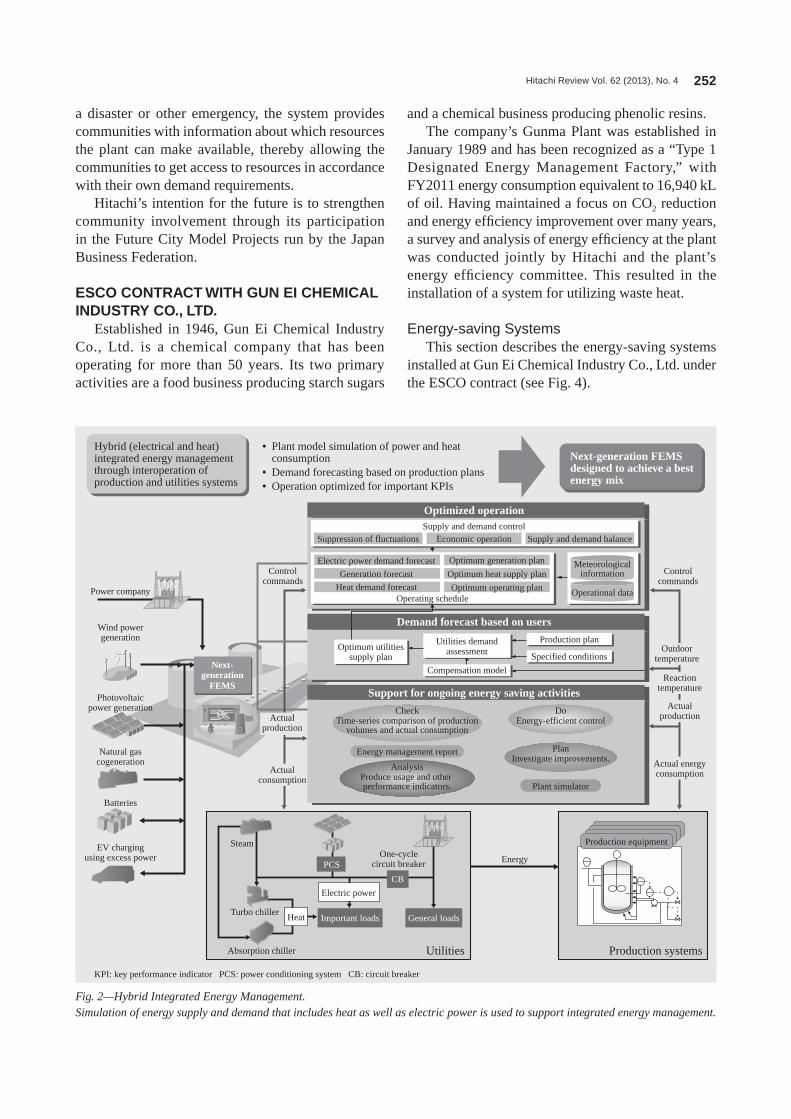
Hybrid Integrated Energy Management for Power and Heat
Plant utility systems include the supply of heat, and this can be retained in piping and machinery without necessarily fitting thermal storage tanks. next-generation FEMS are designed for hybrid integrated energy management, using simulations of supply and demand that include not only electric power but also thermal energy such as these forms of latent heat storage and the generation of power from waste heat (see Fig. 2).
Demonstration Cases at HitachiHitachi provides solutions for social infrastructure
that fuse information and control. In its first step
toward realizing this concept of computer-integrated factories, the company commenced a project in 2011 that involved the installation of 940 kW of photovoltaic power generation, 4.2 MWh of batteries, and an FEMS (see Fig. 3).
Starting initially with a system for cutting peak demand and “visualization” capabilities associated with the installation of the photovoltaic power plant and batteries, the intention is that the project scope will expand to also encompass testing of a symbiosis autonomous decentralized energy management system (EMS) and integration with electric vehicle (EV) charging.
The symbiosis autonomous decentralized EMS allows multiple systems to share common objectives by presenting information on resources that each system has available to share with other systems so that these other systems can then autonomously determine the resources they want to access. Specifically, during
Mission-criticalsystems/ERP
Supply chainmanagement
“Visualization,”efficiency
improvementProduction management Energy management
Optimize overall operationthrough coordinated managementand integration of energy supply
plans with production plans.
Site information Site information
Enhanced performance throughongoing activities aimed at improving
production and energy efficiency
Achieve continuous improvement by collecting site informationand repeatedly working through the PDCA cycle.
WMS/WCS• Work instructions• Equipment control
Inward goods andmaterials/pickingand distribution
Production process(machining, assembly)
Packing anddispatch processes
• Work instructions• Equipment control
• Work instructions• Equipment control
• Monitoring• Control
WMS/WCS Energy monitoring (FEMS)
Thermal energy Electrical energy
MES/OPC, FOA
DCS SCADA
Platform
Planning
Management
Plant
Utilities
Photovoltaic powergeneration system
Energy management forminimizing CO2 emissions
Pumps, chillers, compressors
Materials handlingequipment
Monitoring andcontrol system
Components forproduction FA line
UPSAir conditioning
High-voltagedirect inverter
Highly efficientsubstation equipment
Adoption of highlyefficient energy-saving equipment
Use of autonomous decentralizedEMS for interoperation with community
(smart city)
Control of supply and demand to minimizethe unit cost of energy consumed at the plant
Utilitiesbuilding
In-home powergeneration
EV chargingstand
Powerplant
EMS
EMS EMSEMS
EMS
Monitoring of electric powerdistribution equipment
Monitoring of productionline equipment
Monitoring of utilities Other equipment monitoring
Cogeneration system
Energy-efficientlighting and
air conditioning
Unused hydro energy
Lightningprotection systems
Office building
Factory
Eliminate wastethrough “visualization.”
Power systemstabilization control
Fig. 1—Concept of Computer-integrated Factories Made Possible by Information and Control Technology.The concept aims to achieve energy efficiency, stable plant operation, and higher productivity through the overall optimization of production and energy.
PDCA: plan, do, check, and act ERP: enterprise resource planning DCS: distributed control system SCADA: supervisory control and data acquisition WMS: warehouse management system WCS: warehouse control system MES: manufacturing execution system oPC: olE* for Process Control FoA: flow-oriented approach FEMS: factory energy management system EMS: energy management system EV: electric vehicle UPS: uninterruptible power system FA: factory automation* olE is the name of software developed by Microsoft Corporation of the USA.
Hitachi Review Vol. 62 (2013), No. 4 252
and a chemical business producing phenolic resins.The company’s gunma Plant was established in
January 1989 and has been recognized as a “Type 1 Designated Energy Management Factory,” with FY2011 energy consumption equivalent to 16,940 kl of oil. Having maintained a focus on Co2 reduction and energy efficiency improvement over many years, a survey and analysis of energy efficiency at the plant was conducted jointly by Hitachi and the plant’s energy efficiency committee. This resulted in the installation of a system for utilizing waste heat.
Energy-saving SystemsThis section describes the energy-saving systems
installed at gun Ei Chemical Industry Co., ltd. under the ESCo contract (see Fig. 4).
a disaster or other emergency, the system provides communities with information about which resources the plant can make available, thereby allowing the communities to get access to resources in accordance with their own demand requirements.
Hitachi’s intention for the future is to strengthen community involvement through its participation in the Future City Model Projects run by the Japan Business Federation.
ESCO CONTRACT WITH GUN EI CHEMICAL INDUSTRY CO., LTD.
Established in 1946, gun Ei Chemical Industry Co., ltd. is a chemical company that has been operating for more than 50 years. Its two primary activities are a food business producing starch sugars
Suppression of fluctuations Economic operationSupply and demand control
Optimized operation
Demand forecast based on users
Support for ongoing energy saving activities
Operating schedule
Electric power demand forecast Optimum generation plan
Optimum operating plan
Meteorologicalinformation
Operational data
Controlcommands
Controlcommands
Power company
Wind powergeneration
Photovoltaicpower generation
Batteries
EV chargingusing excess power
Natural gascogeneration
Next-generation
FEMS
Energy
Optimum heat supply plan
Heat demand forecast
Optimum utilitiessupply plan
Utilities demandassessment
Production plan
Specified conditions
Compensation model
CheckTime-series comparison of production
volumes and actual consumption
DoEnergy-efficient control
PlanInvestigate improvements.
Plant simulator
Energy management report
AnalysisProduce usage and other performance indicators.
Generation forecast
Supply and demand balance
• Plant model simulation of power and heat consumption
• Demand forecasting based on production plans• Operation optimized for important KPIs
Next-generation FEMS designed to achieve a best energy mix
Steam
Absorption chiller
Heat
Electric power
PCS
CB
Important loads General loads
One-cyclecircuit breaker
Utilities Production systems
Turbo chiller
Outdoortemperature
Reactiontemperature
ActualproductionActual
production
Actualconsumption
Actual energyconsumption
Hybrid (electrical and heat) integrated energy management through interoperation of production and utilities systems
Production equipment
Fig. 2—Hybrid Integrated Energy Management.Simulation of energy supply and demand that includes heat as well as electric power is used to support integrated energy management.
KPI: key performance indicator PCS: power conditioning system CB: circuit breaker
Factory and Community Energy-saving System Solutions for Low-carbon Society 253
(3) Waste hot water recovery systemWastewater from the production process is
discharged from the plant after appropriate treatment, including steam heating. The water exits the steam heating process at approximately 90°C and was being discharged without its energy being utilized. Accordingly, Hitachi installed a waste hot water recovery system that utilizes the waste hot water to heat clean water.(4) Air conditioning heat pump/chiller
The air conditioning in the headquarters and laboratory building is based on use of a central heat source, with a steam absorption chiller used for cooling and a steam/hot water heat exchanger for heating. Because the aging steam absorption chiller was due for upgrading, Hitachi undertook a comparative study of the alternatives to simply replacing the unit with another of the same type. Their ultimate conclusion was that an air conditioning heat pump/chiller represented the best option because it was able to fit in the space available while having lower running costs than the current systems for both heating and cooling.(5) Air compressors
The three aging units at the no. 1 Saccharification Plant included a compressor that frequently switched
(1) Waste steam recovery systemThe production process at the no. 1 Resin Plant
used high-pressure steam in evaporators. Steam that had served its purpose in the evaporators was subsequently released into the atmosphere as waste. Although they had previously considered heat recovery from this waste steam, it had been ruled out by the characteristics of the reaction in the evaporators, which could not tolerate back pressure at the steam outlet. Subsequently, Hitachi conducted a study into how heat recovery could be performed without creating back pressure. Based on the results of this study, they were able to install a waste steam recovery system based around a shell and tube heat exchanger that could recover the latent heat from the steam without back pressure.(2) Waste gas steam boiler
The plant uses a sludge dryer that dries and deodorizes the sludge discharged from the production process. This in turn produces waste gas at approximately 400°C from the deodorizing furnace that was being discharged into the atmosphere without its energy being utilized. Two ways of recovering heat from the waste gas are to use it to produce either steam or hot water. As the gunma Plant requires a large amount of steam, it chose to install a waste gas steam boiler at the final stage of the sludge dryer.
Photovoltaic PCS
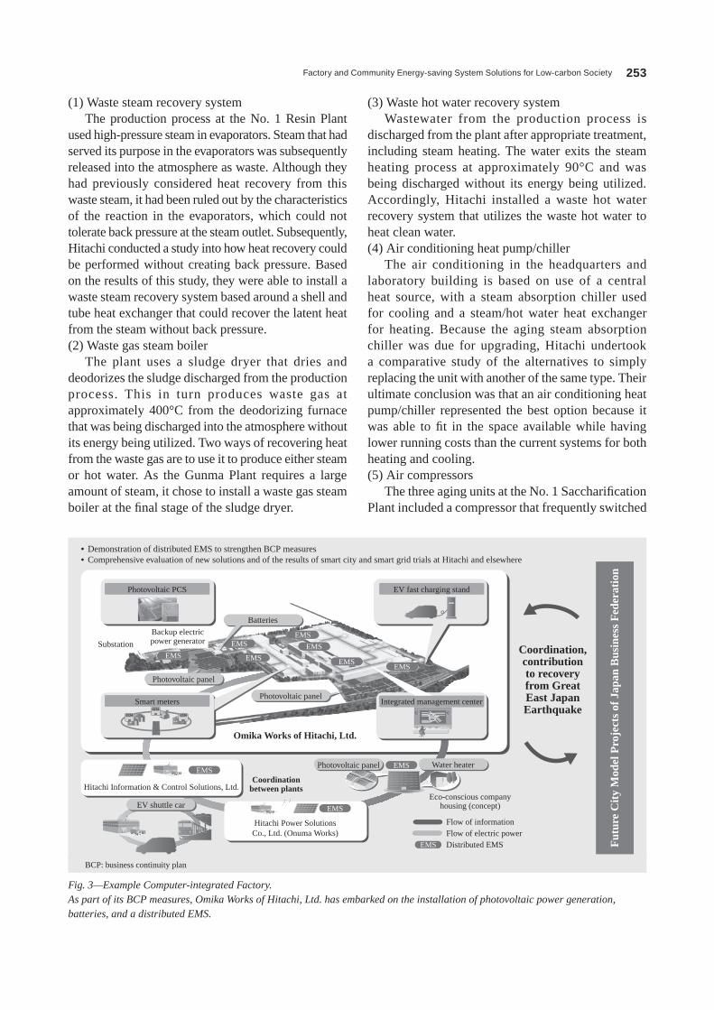
• Demonstration of distributed EMS to strengthen BCP measures• Comprehensive evaluation of new solutions and of the results of smart city and smart grid trials at Hitachi and elsewhere
EV fast charging stand
Photovoltaic panel
EV shuttle car
EMSEMS
EMS
EMS
EMS
EMS
EMS
EMS
EMS
EMS
EMS
Photovoltaic panel
Substation
Hitachi Information & Control Solutions, Ltd.Coordination
between plants
Omika Works of Hitachi, Ltd.
Fut
ure
Cit
y M
odel
Pro
ject
s of
Jap
an B
usin
ess
Fed
erat
ion
Coordination,contributionto recoveryfrom GreatEast JapanEarthquake
Eco-conscious companyhousing (concept)
Flow of informationFlow of electric powerDistributed EMS
Hitachi Power SolutionsCo., Ltd. (Onuma Works)
Batteries
Photovoltaic panel Water heater
Backup electricpower generator
Integrated management centerSmart meters
1234 1234
1234
Fig. 3—Example Computer-integrated Factory.As part of its BCP measures, Omika Works of Hitachi, Ltd. has embarked on the installation of photovoltaic power generation, batteries, and a distributed EMS.
BCP: business continuity plan
Hitachi Review Vol. 62 (2013), No. 4 254
It needs to be emphasized that building the organic energy-saving systems described in this example demands not only the capabilities of the ESCo supplier, but also the wholehearted cooperation of the client. That is, success is difficult to achieve if all of the effort is put in by one side only. Rather, it comes about through the ESCo supplier and client working together. In its search for ways of reducing Co2 emissions, Hitachi has for a long time enjoyed
between loading and unloading operations and another that works solely for unloading operation for long periods of time. The no. 2 Resin Plant, meanwhile, which was fitted with comparatively new equipment, also had compressors that frequently switched between loading and unloading operations. After reviewing the conditions of the equipment at each plant, the no. 1 Saccharification Plant was upgraded with three new 37-kW units (one of which was inverter-driven) together with a system for controlling the number of units in operation, and the existing compressors at the no. 2 Resin Plant were retrofitted with the system for controlling the number of units in operation, and one was upgraded to inverter drive.(6) Closed-loop operation of vacuum pump line
Plant water (treated bore water) is used as seal water for the vacuum pumps in the no. 1 Saccharification Plant. Because the temperature of the seal water affects the degree of vacuum produced by the vacuum pumps if it becomes too hot, the plant had previously used an open-loop configuration in which the plant water was discharged after use. After assessing the actual situation, a closed-loop system was introduced whereby the seal water is indirectly cooled by water from an existing cooling tower and reused.
Benefits of Introducing ESCO ContractThe energy-saving systems described above
represented a step forward in transforming the plant into one suitable for a low-carbon society.
Optimal planfor coordination
of supply and demand
Best mix of electricaland thermal energy
Consumer-sidethermal load
controlxEMS
interoperationfunctions
Distributionof heat and
cooling acrossdifferent areas
HousingOffices
BEMSHEMS xEMS
District cooling system
Railway
Commercialfacilities
Hospital
Fig. 5—Scope of Smart Energy Network and Functional Overview.The network combines electric power with heat, renewable energy, and previously untapped energy sources, and optimizes energy use through exchanges between consumers.
HEMS: home energy management system BEMS: building and energy management system
Closed-loop operationof vacuum pump line
Upgrade to two-stageair-cooled compressor
Installation of invertersfor compressors, andsystem for controllingwhich units to operate
Waste gas recovery systemfor deodorizing furnace
Waste hot water recovery system for waste fluid tank
Evaporator waste steam recovery system
No. 1Saccharifi-cation Plant
Boilerroom
No. 2Resin Plant
No. 1Resin Plant
Laboratory R&D center
Heatexchanger
Waste fluidtreatment tank
Waste steamheat recovery unit Evaporator
Hot water
To boiler room
Waste hot waterrecovery system
Fresh water tankTo boilersupply water
Deodorizingfurnace
Waste gassteam boiler
Steam
Wastegas
Wastehot water
Wastesteam
Heatexchanger
Heatexchanger
Hot water
Compressor
Boilersupplywater
Boilersupplywater
Upgrades to airconditioning heatpump/chillers
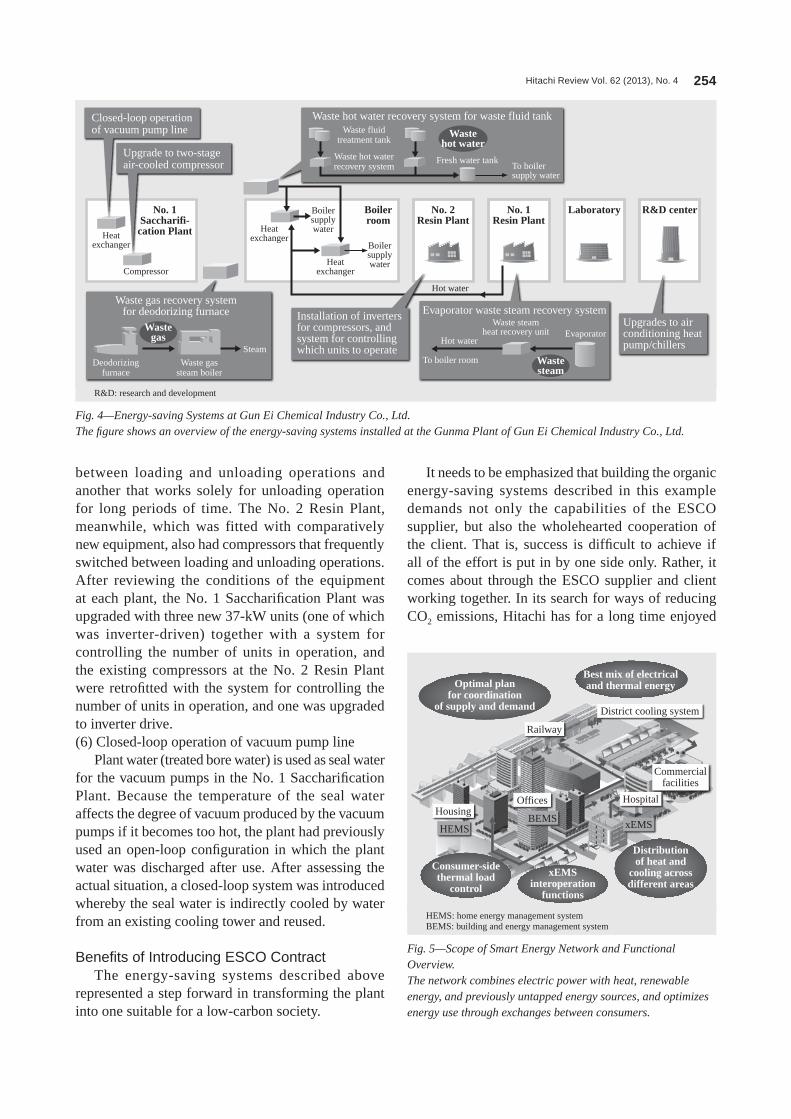
Fig. 4—Energy-saving Systems at Gun Ei Chemical Industry Co., Ltd.The figure shows an overview of the energy-saving systems installed at the Gunma Plant of Gun Ei Chemical Industry Co., Ltd.
R&D: research and development
Factory and Community Energy-saving System Solutions for Low-carbon Society 255
This has prompted new initiatives involving smart energy networks that allow the sharing of energy (electric power and heat) between different users, with the prospect of their application in the new urban developments that will form part of regional reconstruction.
Smart energy networks combine renewable energy and highly efficient cogeneration systems (CgSs) to deliver an optimal supply of energy at the community level. They need to exercise optimal control within their geographical scope over both the consumers of electric power and heat energy on the demand side and the consolidated suppliers who serve them (see Fig. 5).
unstinting cooperation from the technical staff at the gunma Plant of gun Ei Chemical Industry Co., ltd.
The plan for the future is to make further reductions in Co2 emissions by installing cogeneration.
SMART ENERGY NETWORKIn addition to the energy efficiency and
environmental aspects, the period since the great East Japan Earthquake has seen rapid growth in demand in Japan for the optimized operation of a best mix of energy sources (electric power and heat) across entire communities, and their use in ways that go beyond the boundaries between individual companies or facilities.
Bi-directional exchanges of heat
Photovoltaic panels
Photovoltaic panels
Solar heat collectors
Solar heat collectors
Heat supply system
Sun-Heim Arakawa nursing home run by Arakawa District
Photovoltaic panels(rooftop)
Steam-driven solarabsorption chiller
Gas-powered solarabsorption chiller
Inverter-driventurbocooler
Triple-effectnatural chiller
Vacuum tube solarheat collector
Hot water (solar heat, CGS waste heat, heating, hot water supply)
Source: Tokyo Gas Co., Ltd. pamphlet
Electric power
E F G H I
D
J
BA
C
100 m
Cold water
Improves energy security.Helps stabilize electric power grid.Energy-efficient, low-carbon
Senju Techno-StationEquipment location
Model house
ArakawaWard road
Building A
Building B
Building Cenergy center
Senju Techno-Station
Meiji Dori Avenue
Hot watersystem
Heat supplysystem
CGS
CGS
CGS
A
G I JHF
Vacuum tube solarheat collector
Steam-drivenabsorption heat pump
370-kW gas enginecogeneration
Photovoltaic panels(wall-mounted)
C EDB
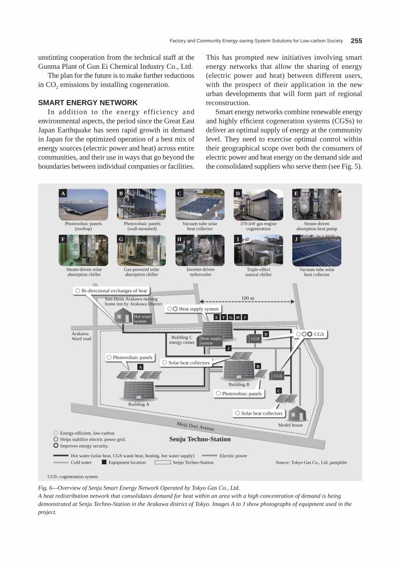
Fig. 6—Overview of Senju Smart Energy Network Operated by Tokyo Gas Co., Ltd.A heat redistribution network that consolidates demand for heat within an area with a high concentration of demand is being demonstrated at Senju Techno-Station in the Arakawa district of Tokyo. Images A to J show photographs of equipment used in the project.
CgS: cogeneration system

Hitachi Review Vol. 62 (2013), No. 4 256
control, and the results of the demonstration project will in the future be applied in other areas undergoing redevelopment.
CONCLUSIONSThis article has described, with examples, Hitachi’s
concept of computer-integrated factories in which the overall optimization of production and energy in coordination with production plans achieves a best mix of energy sources and integrated management of electrical and thermal energy.
The article has also described an ESCo contract in which the client site and solution provider worked
Hitachi is current ly col laborat ing with energy suppliers and others on the trialing and commercialization of community-level smart energy networks.
Demonstration Project at Tokyo Gas Co., Ltd.The Senju Smart Energy network is a demonstration
project being run by Tokyo gas Co., ltd. at Senju Techno-Station in the Arakawa district of Tokyo.
This system consists of a heat redistribution network that consolidates demand for heat within an area with a high concentration of demand and combines cogeneration, solar heat collectors, and photovoltaic power generation to exchange heat and electric power between a number of buildings (see Fig. 6).
The project is trialing the following features.(1) Exchange of heat between adjacent buildings(2) Integrated control of heat supply equipment that makes preferential use of solar heat and waste heat from cogeneration(3) Control of cogeneration and turbochillers to compensate for weather-related fluctuations in the output of photovoltaic power generation
The project has also been selected by the Ministry of Economy, Trade and Industry for a program trialing the distributed optimization of different forms of energy.
Table 1 lists the main equipment installed as part of the project.
Preferential Use of Solar Heat and CGS Waste Heat (Integrated Control of Heat Supply)
This system performs supervisory control of the hybrid heat supply system that uses a number of different energy sources, controlling which combination of energy sources to use to optimize energy efficiency. Specifically, the system gives top priority to use of renewable solar heat and previously unused waste heat from heating and cooling. After that, the priority of heat sources is: (1) CgS waste heat, (2) electric power generated by the CgS, and (3) town gas. The control scheme maximizes energy savings and reductions in Co2 emissions.
Demonstration Project and Future DeploymentInstallation of the demonstration project systems
succeeded in reducing Co2 emissions by 35.8% compared to the previous systems (actual results for FY2011).
The demonstrations also confirmed the favorable operational performance of integrated heat source
Type Name Specifications Quantity
CgS
D: gas engine cogeneration 370 kW 1
gas engine cogeneration 700 kW 1
Heat sources
E: Steam-driven absorption heat pump*
• When operated for cooling onlyCooling : 422 kW• When operated for cooling and heatingCooling: 165 kWHeating: 304 kW
1
F: Steam-driven solar absorption chiller* Cooling: 422 kW 1
g: gas-powered solar absorption chiller*
Cooling: 949 kWHeating: 813 kW 2
I: Triple-effect natural chiller
Cooling: 1,125 kWHeating: 658 kW 1
H: Inverter-driven turbocooler* Cooling: 703 kW 1
Air-cooled chiller (screw type) Cooling: 132 kW 1
Vacuum water heater Hot water: 349 kWHeating: 175 kW 1
Multi-tube flow-through boiler 2.0 t/h 1
Photovoltaic panels
CIS compound semiconductor 10 kW 1
CIgS compound semiconductor 10 kW 1
Polycrystalline silicon 30 kW 1
A: Monocrystalline silicon 40 kW 1
B: Monocrystalline silicon + thin film amorphous silicon
16.7 kW 1
Solar heat collector
C: Vacuum tube solar heat collector 130 kW (approx.) 1
J: Vacuum tube solar heat collector 36 kW (approx.) 1
TABlE 1. Key Equipment Installed for Senju Smart Energy networkThe key equipment installed for the demonstration project included CGS and various heat sources.
* Supplied by HitachiCIS: copper indium selenide CIgS: copper indium gallium selenide

Factory and Community Energy-saving System Solutions for Low-carbon Society 257
together to achieve energy savings. A system upgrade achieved energy savings through measures such as the utilization of discharged hot water, a previously overlooked source of heat.
Also discussed were the smart energy networks that extend the energy efficiency concept beyond individual factories to encompass entire communities.
Takaki TaniguchiJoined Hitachi, Ltd. in 2007, and now works at the I&E Information and Control Systems Engineering Department, Infrastructure Security & Energy Solutions Division, Infrastructure Systems Company. He is currently engaged in coordinating industry and energy system businesses.
ABOUT THE AUTHOR
Hitachi Review Vol. 62 (2013), No. 4 258
Energy Saving Solution for Data Centers
Toshiyuki Oonuki
Yasuo Ono
Obi Onuora
Yasuhiro Kashirajima
OVERVIEW: Hitachi has developed the spot cooling system designed to improve data center energy efficiency, and its product range also includes ceiling suspension type units that improve space efficiency. Hitachi was also contracted by the Ministry of Internal Affairs and Communications to undertake international standardization work in which it demonstrated that the use of spot cooling systems represents best practice for data centers with a high density of installed ICT equipment. A draft containing the results of this work was submitted to the ITU as a formal Japanese proposal and subsequently adopted as a recommendation in November 2011.
INTRODUCTIONDATA center power demands are growing rapidly, driven by advances in the information society that include the faster speeds and greater capacity of information and telecommunications. It has been estimated that the volume of data passing through the Internet will expand by a factor of 190 between 2006 and 2025, during which time the amount of power consumed by information and communication technology (ICT) equipment in Japan will have grown by a factor of five. This has created an urgent need for measures that will reduce data center power consumption(1), (2).
Data center equipment needs to be capable of upgrading to increase capacity and must have the reliability to operate 24 hours a day, 365 days a year. Recent years have seen the emergence of problems such as an increase in power consumption by cooling systems, and also the occurrence of hot spots that are severe enough to impact equipment performance, which results from the increased amount of heat generated by the high-density packaging of ICT equipment.
This article describes the spot cooling system for data centers, and work on international standardization of data center air conditioning systems.
ISSUES FACED BY DATA CENTER AIR CONDITIONING SYSTEMS
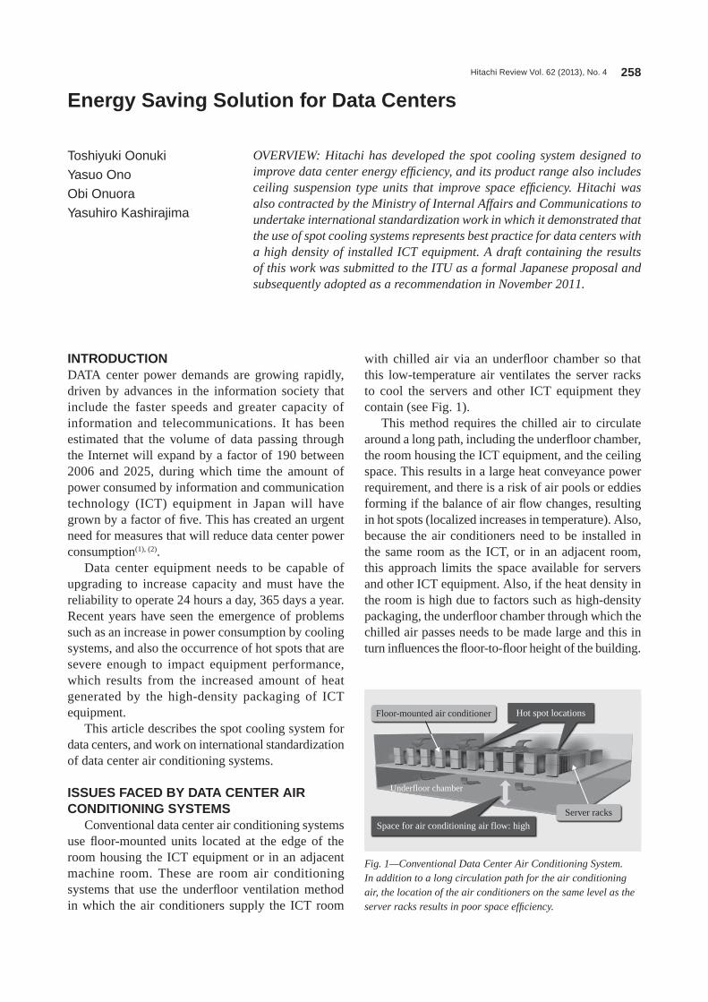
Conventional data center air conditioning systems use floor-mounted units located at the edge of the room housing the ICT equipment or in an adjacent machine room. These are room air conditioning systems that use the underfloor ventilation method in which the air conditioners supply the ICT room
with chilled air via an underfloor chamber so that this low-temperature air ventilates the server racks to cool the servers and other ICT equipment they contain (see Fig. 1).
This method requires the chilled air to circulate around a long path, including the underfloor chamber, the room housing the ICT equipment, and the ceiling space. This results in a large heat conveyance power requirement, and there is a risk of air pools or eddies forming if the balance of air flow changes, resulting in hot spots (localized increases in temperature). Also, because the air conditioners need to be installed in the same room as the ICT, or in an adjacent room, this approach limits the space available for servers and other ICT equipment. Also, if the heat density in the room is high due to factors such as high-density packaging, the underfloor chamber through which the chilled air passes needs to be made large and this in turn influences the floor-to-floor height of the building.
Hot spot locations
Space for air conditioning air flow: high
Underfloor chamber
Floor-mounted air conditioner
Server racks
Fig. 1—Conventional Data Center Air Conditioning System.In addition to a long circulation path for the air conditioning air, the location of the air conditioners on the same level as the server racks results in poor space efficiency.

Energy Saving Solution for Data Centers 259
SPOT COOLING SYSTEMHitachi embarked on the development of natural
circulation of refrigerant (in which heat conveyance is achieved without consuming any power) in 2007, and released the spot cooling system featuring highly efficient heat sources in 2009. A modular data center incorporating spot cooling system won a Best 10 new Products Awards from nikkan Kogyo Shimbun, ltd. in 2010, and the product range has since been extended by the addition of ceiling-suspension type cooling units and other new components.
System OverviewSpot cooling system consists of chilled water-
refrigerant heat exchangers (condensers) that cool the refrigerant, and spot cooling units (evaporators) that cool the air expelled from the servers in the room. For its heat sources, the system uses highly efficient chillers and also free cooling units that use outdoor cold sources to produce chilled water in winter and intermediate seasons. The chilled water cools and condenses the refrigerant in a condenser, and this liquefied refrigerant is gravity-fed to an evaporator that is located at a lower level than the condenser, cooling the air expelled from the servers in the process (a refrigerant pump is used if insufficient head is available for natural circulation). Heat from the ICT equipment is drawn by suction from adjacent hot aisles and cooled air is returned to cold aisles, thereby shortening the circulation path for the air conditioning air and significantly reducing power consumption compared to previous refrigerant reheat type packaged air conditioners (see Fig. 2).
Benefits of System InstallationThe spot cooling system uses ceiling suspension
type spot cooling units (that have recently been added to the product range) installed above hot aisles to shorten the circulation path for air conditioning air and reduce the required heat conveyance power. Together, these and other measures have succeeded firstly in reducing air conditioning power requirements by approximately 60% compared to previous methods*1. Secondly, utilization of the ceiling space has improved the space efficiency for an equivalent floor area by approximately 20% and contributed to customer earnings by increasing the floor space available for ICT equipment. Thirdly, floor-to-floor height has been reduced by around 10% because underfloor space is no longer required for air conditioning air flow (see Fig. 3).
EXAMPLE INSTALLATIONSWhen building a server room for cloud systems,
SoftBank Telecom Corp. installed a spot cooling system that uses natural circulation of refrigerant. Whereas estimates put the average value of power usage effectiveness (PUE), an index of data center energy efficiency, for data centers in Japan at 2.0, the SoftBank facility has significantly improved energy efficiency and reduced its PUE to 1.3 or less measured across the course of a year (see Fig. 4).
Chilledwater-refrigerantheat exchanger
Cooling tower forfan-coil unit
Inverter-driventurbochiller
Coolingtower
Cold water (17°C)
Cold water (12°C)
Refrigerant (22°C) Refrigerant
(18°C)
Data cablesCold
Rac
k
Rac
k
Rac
k
Rac
k
Rac
k
Rac
k
Cold ColdHot Hot Hot
Power cables
* Compared to refrigerant reheat computer package air conditioning system (estimate by Hitachi)
Cold aisle
Capping
Hot aisle
Spot cooling system
Use of spotcooling reduces heat conveyancepower (35%*).
Energy savingsachieved by use ofhighly efficient heat source and free energy (20%*)
Ceiling suspension typespot cooling system
Use natural circulationof refrigerant to reducerefrigerant heatconveyance power(5%*).
Ceiling suspensiontype spot cooling unit
Fig. 2—Overview of Spot Cooling System and Installation Layout.Air conditioning power consumption has been significantly reduced through the use of spot cooling to reduce heat conveyance power and through energy savings achieved by adopting highly efficient heat sources and a free cooling system. Ceiling suspension type units installed in hot aisles separated by capping draw in hot air and blow chilled air into cold aisles.
*1 Estimate by Hitachi: Comparison between conventional computer air conditioning system and spot cooling system configured with a core system (chilled water-refrigerant heat exchanger with maximum cooling capacity of 60 kW), four spot cooling units (ceiling suspension type, maximum cooling capacity of 15 kW/unit), and optional extras (highly efficient heat source and free cooling system).
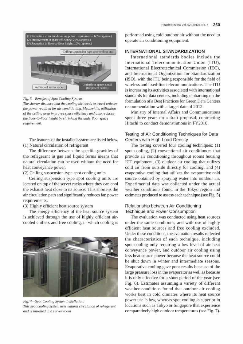
Hitachi Review Vol. 62 (2013), No. 4 260
performed using cold outdoor air without the need to operate air conditioning equipment.
INTERNATIONAL STANDARDIZATIONInternational standards bodies include the
International Telecommunication Union (ITU), International Electrotechnical Commission (IEC), and International organization for Standardization (ISo), with the ITU being responsible for the field of wireless and fixed-line telecommunications. The ITU is increasing its activities associated with international standards for data centers, including embarking on the formulation of a Best Practices for green Data Centers recommendation with a target date of 2012.
Ministry of Internal Affairs and Communications spent three years on a draft proposal, contracting Hitachi to conduct demonstrations in FY2010.
Testing of Air Conditioning Techniques for Data Centers with High Load Density
The testing covered four cooling techniques: (1) spot cooling, (2) conventional air conditioners that provide air conditioning throughout rooms housing ICT equipment, (3) outdoor air cooling that utilizes cold air from outside directly for cooling, and (4) evaporative cooling that utilizes the evaporative cold source obtained by spraying water into outdoor air. Experimental data was collected under the actual weather conditions found in the Tokyo region and estimates produced to assess each technique (see Fig. 5)
Relationship between Air Conditioning Technique and Power Consumption
The evaluation was conducted using heat sources under the same conditions, and with use of highly efficient heat sources and free cooling excluded. Under these conditions, the evaluation results reflected the characteristics of each technique, including spot cooling only requiring a low level of air heat conveyance power, and outdoor air cooling using less heat source power because the heat source could be shut down in winter and intermediate seasons. Evaporative cooling gave poor results because of the large pressure loss in the evaporator as well as because it is only effective for a short period of the year (see Fig. 6). Estimates assuming a variety of different weather conditions found that outdoor air cooling works best in cold climates where its heat source power use is low, whereas spot cooling is superior in locations such as Tokyo or Singapore that experience comparatively high outdoor temperatures (see Fig. 7).
The features of the installed system are listed below.(1) natural circulation of refrigerant
The difference between the specific gravities of the refrigerant in gas and liquid forms means that natural circulation can be used without the need for heat conveyance power.(2) Ceiling suspension type spot cooling units
Ceiling suspension type spot cooling units are located on top of the server racks where they can cool the exhaust heat close to its source. This shortens the air circulation path and significantly reduces fan power requirements.(3) Highly efficient heat source system
The energy efficiency of the heat source system is achieved through the use of highly efficient air-cooled chillers and free cooling, in which cooling is
Fig. 4—Spot Cooling System Installation.This spot cooling system uses natural circulation of refrigerant and is installed in a server room.
(1) Reduction in air conditioning power requirements: 60% (approx.)(2) Improvement in space efficiency: 20% (approx.)(3) Reduction in floor-to-floor height: 10% (approx.)
Underfloor space: small(for power cables)
Ceiling suspension type spot cooling unit
Additional server racks
Fig. 3—Benefits of Spot Cooling System.The shorter distance that the cooling air needs to travel reduces the power required for air conditioning. Meanwhile, utilization of the ceiling area improves space efficiency and also reduces the floor-to-floor height by shrinking the underfloor space requirement.
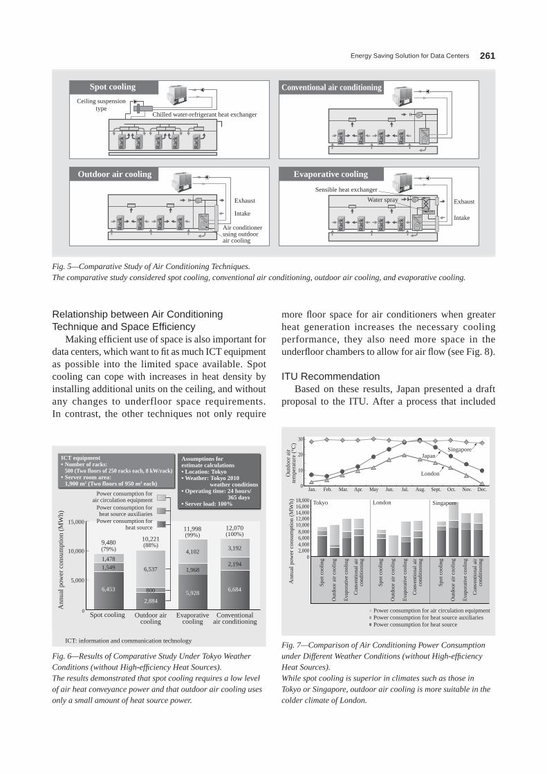
Energy Saving Solution for Data Centers 261
more floor space for air conditioners when greater heat generation increases the necessary cooling performance, they also need more space in the underfloor chambers to allow for air flow (see Fig. 8).
ITU RecommendationBased on these results, Japan presented a draft
proposal to the ITU. After a process that included
Relationship between Air Conditioning Technique and Space Efficiency
Making efficient use of space is also important for data centers, which want to fit as much ICT equipment as possible into the limited space available. Spot cooling can cope with increases in heat density by installing additional units on the ceiling, and without any changes to underfloor space requirements. In contrast, the other techniques not only require
Spot cooling
Outdoor air cooling
Conventional air conditioning
Evaporative cooling
Ceiling suspensiontype
Chilled water-refrigerant heat exchanger
Exhaust
Air conditionerusing outdoorair cooling
Rac
kR
ack
Rac
k
Rac
k
Rac
k
Rac
kR
ack
Rac
k
Rac
k
Rac
k
Rac
k
Rac
k
Rac
k
Rac
k
Rac
k
Rac
k
Rac
k
Intake
Exhaust
Sensible heat exchanger
Water spray
Intake
Fig. 5—Comparative Study of Air Conditioning Techniques.The comparative study considered spot cooling, conventional air conditioning, outdoor air cooling, and evaporative cooling.
9,480(79%)
1,478
1,549
6,453
6,537
4,1023,192
2,1941,968
800
2,8845,928
6,684
15,000
10,000
5,000
10,221(88%)
11,998(99%)
12,070(100%)
0
ICT equipment• Number of racks:
500 (Two floors of 250 racks each, 8 kW/rack)• Server room area:
1,900 m2 (Two floors of 950 m2 each)
Assumptions forestimate calculations• Location: Tokyo• Weather: Tokyo 2010 weather conditions• Operating time: 24 hours/ 365 days• Server load: 100%
Ann
ual p
ower
con
sum
ptio
n (M
Wh)
Power consumption forair circulation equipment
Power consumption forheat source auxiliaries
Spot cooling Outdoor aircooling
Evaporativecooling
Conventionalair conditioning
Power consumption forheat source
ICT: information and communication technology
Fig. 6—Results of Comparative Study Under Tokyo Weather Conditions (without High-efficiency Heat Sources).The results demonstrated that spot cooling requires a low level of air heat conveyance power and that outdoor air cooling uses only a small amount of heat source power.
Out
door
air
tem
pera
ture
(°C
)
Japan
Tokyo
Singapore
Singapore
London
London
Spot
coo
ling
Out
door
air
coo
ling
Eva
pora
tive
cool
ing
Con
vent
iona
l air
cond
ition
ing
Spot
coo
ling
Out
door
air
coo
ling
Eva
pora
tive
cool
ing
Con
vent
iona
l air
cond
ition
ing
Spot
coo
ling
Out
door
air
coo
ling
Eva
pora
tive
cool
ing
Con
vent
iona
l air
cond
ition
ing
Ann
ual p
ower
con
sum
ptio
n (M
Wh) 18,000
30
20
10
0Jan. Feb. Mar. Apr. May Jun. Jul. Aug. Oct. Nov. Dec.Sept.
16,00014,00012,00010,0008,0006,0004,0002,000
Power consumption for air circulation equipmentPower consumption for heat source auxiliariesPower consumption for heat source
0
Fig. 7—Comparison of Air Conditioning Power Consumption under Different Weather Conditions (without High-efficiency Heat Sources).While spot cooling is superior in climates such as those in Tokyo or Singapore, outdoor air cooling is more suitable in the colder climate of London.
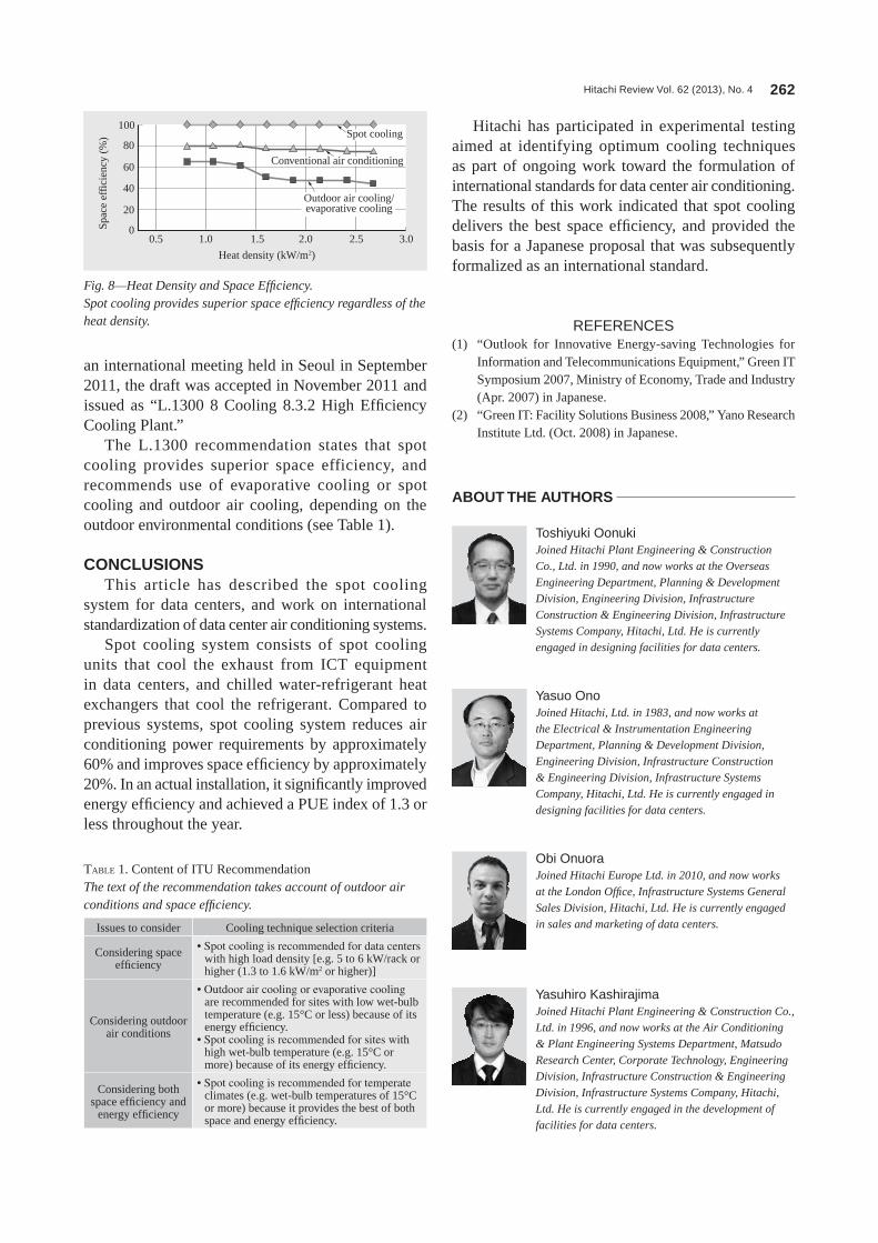
Hitachi Review Vol. 62 (2013), No. 4 262
Hitachi has participated in experimental testing aimed at identifying optimum cooling techniques as part of ongoing work toward the formulation of international standards for data center air conditioning. The results of this work indicated that spot cooling delivers the best space efficiency, and provided the basis for a Japanese proposal that was subsequently formalized as an international standard.
REFERENCES(1) “outlook for Innovative Energy-saving Technologies for
Information and Telecommunications Equipment,” green IT Symposium 2007, Ministry of Economy, Trade and Industry (Apr. 2007) in Japanese.
(2) “green IT: Facility Solutions Business 2008,” Yano Research Institute ltd. (oct. 2008) in Japanese.
an international meeting held in Seoul in September 2011, the draft was accepted in november 2011 and issued as “l.1300 8 Cooling 8.3.2 High Efficiency Cooling Plant.”
The l.1300 recommendation states that spot cooling provides superior space efficiency, and recommends use of evaporative cooling or spot cooling and outdoor air cooling, depending on the outdoor environmental conditions (see Table 1).
CONCLUSIONSThis article has described the spot cooling
system for data centers, and work on international standardization of data center air conditioning systems.
Spot cooling system consists of spot cooling units that cool the exhaust from ICT equipment in data centers, and chilled water-refrigerant heat exchangers that cool the refrigerant. Compared to previous systems, spot cooling system reduces air conditioning power requirements by approximately 60% and improves space efficiency by approximately 20%. In an actual installation, it significantly improved energy efficiency and achieved a PUE index of 1.3 or less throughout the year.
Spac
e ef
fici
ency
(%
)
Heat density (kW/m2)
Outdoor air cooling/evaporative cooling
Conventional air conditioning
Spot cooling100
80
60
40
20
00.5 1.0 1.5 2.0 2.5 3.0
Fig. 8—Heat Density and Space Efficiency.Spot cooling provides superior space efficiency regardless of the heat density.
Issues to consider Cooling technique selection criteria
Considering space efficiency
• Spot cooling is recommended for data centers with high load density [e.g. 5 to 6 kW/rack or higher (1.3 to 1.6 kW/m2 or higher)]
Considering outdoor air conditions
• Outdoor air cooling or evaporative cooling are recommended for sites with low wet-bulb temperature (e.g. 15°C or less) because of its energy efficiency.
• Spot cooling is recommended for sites with high wet-bulb temperature (e.g. 15°C or more) because of its energy efficiency.
Considering both space efficiency and
energy efficiency
• Spot cooling is recommended for temperate climates (e.g. wet-bulb temperatures of 15°C or more) because it provides the best of both space and energy efficiency.
TABlE 1. Content of ITU RecommendationThe text of the recommendation takes account of outdoor air conditions and space efficiency.
Toshiyuki OonukiJoined Hitachi Plant Engineering & Construction Co., Ltd. in 1990, and now works at the Overseas Engineering Department, Planning & Development Division, Engineering Division, Infrastructure Construction & Engineering Division, Infrastructure Systems Company, Hitachi, Ltd. He is currently engaged in designing facilities for data centers.
Obi OnuoraJoined Hitachi Europe Ltd. in 2010, and now works at the London Office, Infrastructure Systems General Sales Division, Hitachi, Ltd. He is currently engaged in sales and marketing of data centers.
Yasuo OnoJoined Hitachi, Ltd. in 1983, and now works at the Electrical & Instrumentation Engineering Department, Planning & Development Division,
Engineering Division, Infrastructure Construction & Engineering Division, Infrastructure Systems Company, Hitachi, Ltd. He is currently engaged in designing facilities for data centers.
Yasuhiro KashirajimaJoined Hitachi Plant Engineering & Construction Co., Ltd. in 1996, and now works at the Air Conditioning & Plant Engineering Systems Department, Matsudo Research Center, Corporate Technology, Engineering Division, Infrastructure Construction & Engineering Division, Infrastructure Systems Company, Hitachi, Ltd. He is currently engaged in the development of facilities for data centers.
ABOUT THE AUTHORS
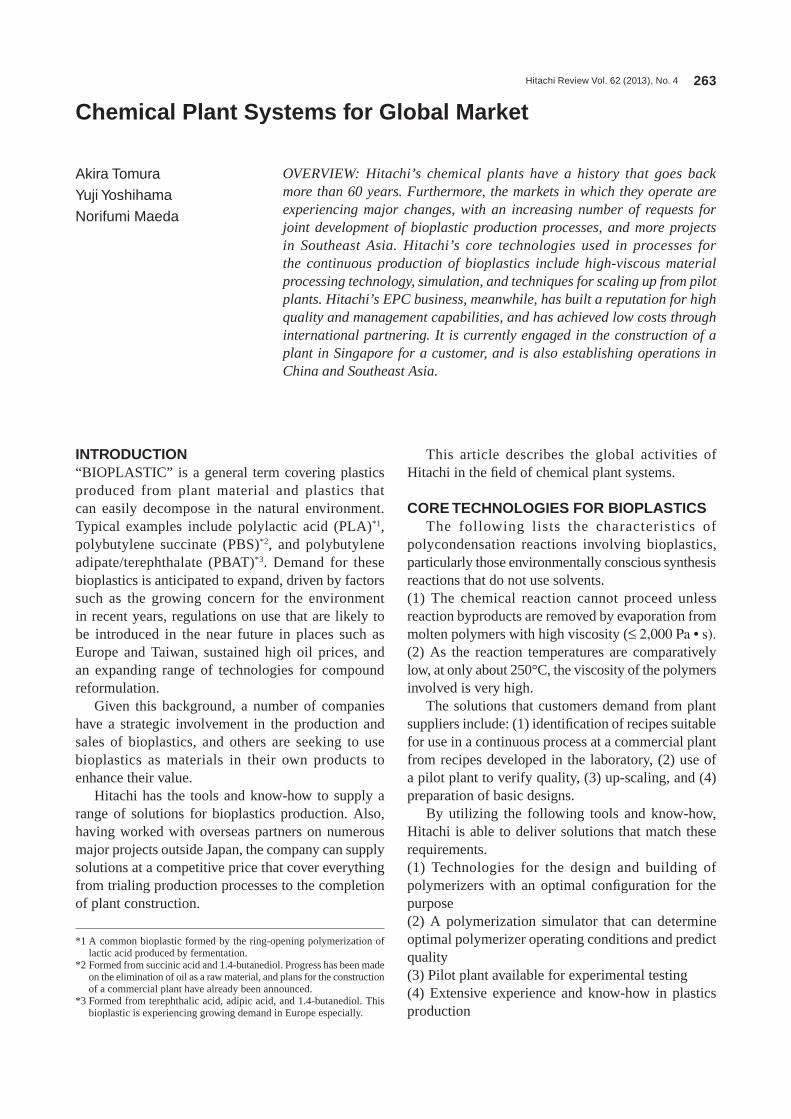
Hitachi Review Vol. 62 (2013), No. 4 263
Chemical Plant Systems for Global Market
Akira Tomura
Yuji Yoshihama
Norifumi Maeda
OVERVIEW: Hitachi’s chemical plants have a history that goes back more than 60 years. Furthermore, the markets in which they operate are experiencing major changes, with an increasing number of requests for joint development of bioplastic production processes, and more projects in Southeast Asia. Hitachi’s core technologies used in processes for the continuous production of bioplastics include high-viscous material processing technology, simulation, and techniques for scaling up from pilot plants. Hitachi’s EPC business, meanwhile, has built a reputation for high quality and management capabilities, and has achieved low costs through international partnering. It is currently engaged in the construction of a plant in Singapore for a customer, and is also establishing operations in China and Southeast Asia.
INTRODUCTION“BIoPlASTIC” is a general term covering plastics produced from plant material and plastics that can easily decompose in the natural environment. Typical examples include polylactic acid (PlA)*1, polybutylene succinate (PBS)*2, and polybutylene adipate/terephthalate (PBAT)*3. Demand for these bioplastics is anticipated to expand, driven by factors such as the growing concern for the environment in recent years, regulations on use that are likely to be introduced in the near future in places such as Europe and Taiwan, sustained high oil prices, and an expanding range of technologies for compound reformulation.
given this background, a number of companies have a strategic involvement in the production and sales of bioplastics, and others are seeking to use bioplastics as materials in their own products to enhance their value.
Hitachi has the tools and know-how to supply a range of solutions for bioplastics production. Also, having worked with overseas partners on numerous major projects outside Japan, the company can supply solutions at a competitive price that cover everything from trialing production processes to the completion of plant construction.
This article describes the global activities of Hitachi in the field of chemical plant systems.
CORE TECHNOLOGIES FOR BIOPLASTICSThe following lists the characteristics of
polycondensation reactions involving bioplastics, particularly those environmentally conscious synthesis reactions that do not use solvents.(1) The chemical reaction cannot proceed unless reaction byproducts are removed by evaporation from molten polymers with high viscosity (≤ 2,000 Pa • s).(2) As the reaction temperatures are comparatively low, at only about 250°C, the viscosity of the polymers involved is very high.
The solutions that customers demand from plant suppliers include: (1) identification of recipes suitable for use in a continuous process at a commercial plant from recipes developed in the laboratory, (2) use of a pilot plant to verify quality, (3) up-scaling, and (4) preparation of basic designs.
By utilizing the following tools and know-how, Hitachi is able to deliver solutions that match these requirements.(1) Technologies for the design and building of polymerizers with an optimal configuration for the purpose(2) A polymerization simulator that can determine optimal polymerizer operating conditions and predict quality(3) Pilot plant available for experimental testing(4) Extensive experience and know-how in plastics production
*1 A common bioplastic formed by the ring-opening polymerization of lactic acid produced by fermentation.
*2 Formed from succinic acid and 1.4-butanediol. Progress has been made on the elimination of oil as a raw material, and plans for the construction of a commercial plant have already been announced.
*3 Formed from terephthalic acid, adipic acid, and 1.4-butanediol. This bioplastic is experiencing growing demand in Europe especially.
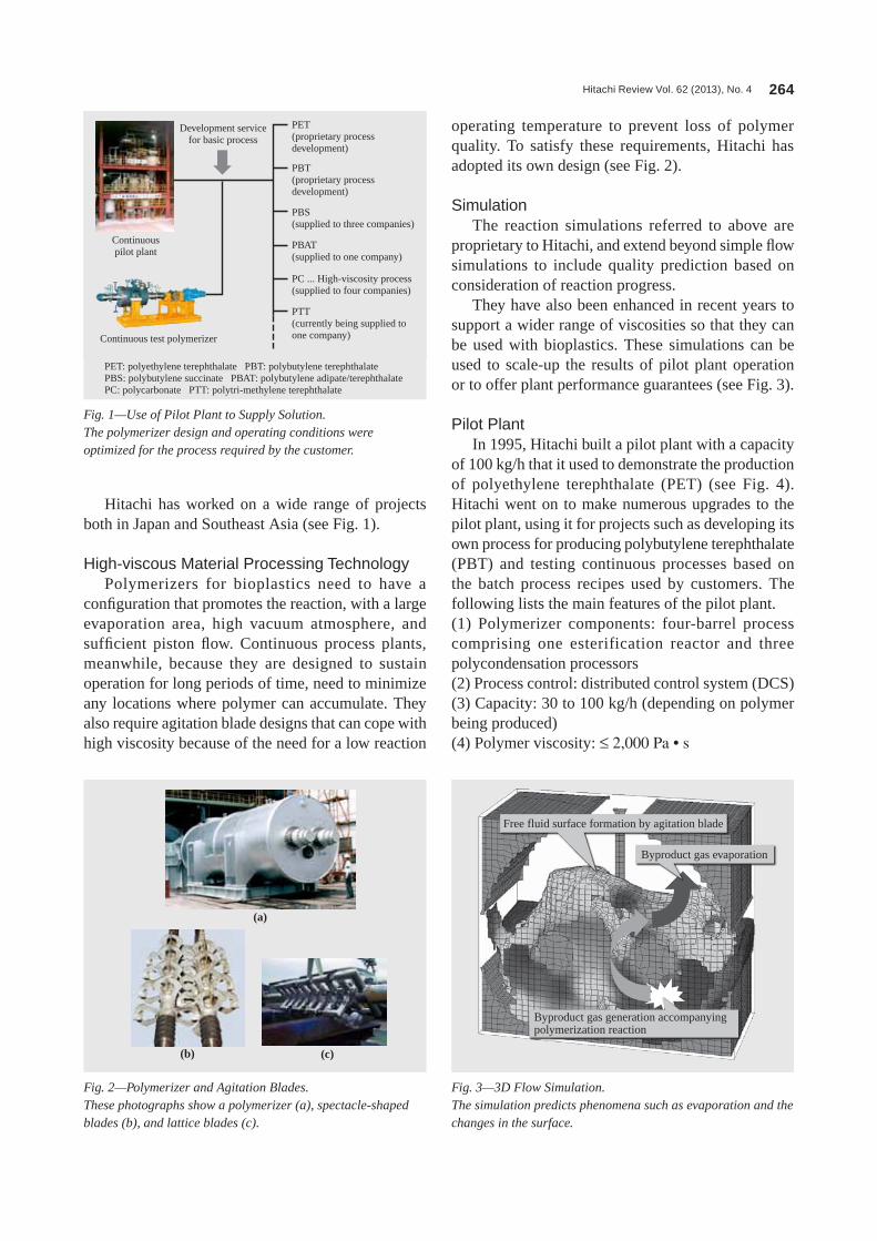
Hitachi Review Vol. 62 (2013), No. 4 264
Hitachi has worked on a wide range of projects both in Japan and Southeast Asia (see Fig. 1).
High-viscous Material Processing TechnologyPolymerizers for bioplastics need to have a
configuration that promotes the reaction, with a large evaporation area, high vacuum atmosphere, and sufficient piston flow. Continuous process plants, meanwhile, because they are designed to sustain operation for long periods of time, need to minimize any locations where polymer can accumulate. They also require agitation blade designs that can cope with high viscosity because of the need for a low reaction
operating temperature to prevent loss of polymer quality. To satisfy these requirements, Hitachi has adopted its own design (see Fig. 2).
SimulationThe reaction simulations referred to above are
proprietary to Hitachi, and extend beyond simple flow simulations to include quality prediction based on consideration of reaction progress.
They have also been enhanced in recent years to support a wider range of viscosities so that they can be used with bioplastics. These simulations can be used to scale-up the results of pilot plant operation or to offer plant performance guarantees (see Fig. 3).
Pilot PlantIn 1995, Hitachi built a pilot plant with a capacity
of 100 kg/h that it used to demonstrate the production of polyethylene terephthalate (PET) (see Fig. 4). Hitachi went on to make numerous upgrades to the pilot plant, using it for projects such as developing its own process for producing polybutylene terephthalate (PBT) and testing continuous processes based on the batch process recipes used by customers. The following lists the main features of the pilot plant.(1) Polymerizer components: four-barrel process comprising one esterification reactor and three polycondensation processors(2) Process control: distributed control system (DCS)(3) Capacity: 30 to 100 kg/h (depending on polymer being produced)(4) Polymer viscosity: ≤ 2,000 Pa • s
Fig. 1—Use of Pilot Plant to Supply Solution.The polymerizer design and operating conditions were optimized for the process required by the customer.
Continuouspilot plant
Continuous test polymerizer
Development servicefor basic process
PET(proprietary process development)
PBT(proprietary process development)
PBS(supplied to three companies)
PBAT(supplied to one company)
PC ... High-viscosity process (supplied to four companies)
PTT(currently being supplied to one company)
PET: polyethylene terephthalate PBT: polybutylene terephthalate PBS: polybutylene succinate PBAT: polybutylene adipate/terephthalate PC: polycarbonate PTT: polytri-methylene terephthalate
Fig. 2—Polymerizer and Agitation Blades.These photographs show a polymerizer (a), spectacle-shaped blades (b), and lattice blades (c).
(a)
(b) (c)
Fig. 3—3D Flow Simulation.The simulation predicts phenomena such as evaporation and the changes in the surface.
Free fluid surface formation by agitation blade
Byproduct gas evaporation
Byproduct gas generation accompanyingpolymerization reaction
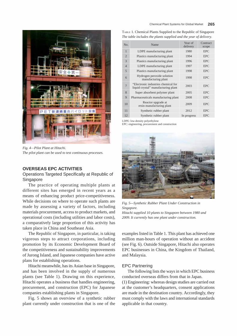
Chemical Plant Systems for Global Market 265
examples listed in Table 1. This plant has achieved one million man-hours of operation without an accident (see Fig. 6). outside Singapore, Hitachi also operates EPC businesses in China, the Kingdom of Thailand, and Malaysia.
EPC PartneringThe following lists the ways in which EPC business
conducted overseas differs from that in Japan.(1) Engineering: whereas design studies are carried out at the customer’s headquarters, consent applications are made in the destination country. Accordingly, they must comply with the laws and international standards applicable in that country.
OVERSEAS EPC ACTIVITIESOperations Targeted Specifically at Republic of Singapore
The practice of operating multiple plants at different sites has emerged in recent years as a means of enhancing product price-competitiveness. While decisions on where to operate such plants are made by assessing a variety of factors, including materials procurement, access to product markets, and operational costs (including utilities and labor costs), a comparatively large proportion of this activity has taken place in China and Southeast Asia.
The Republic of Singapore, in particular, is taking vigorous steps to attract corporations, including promotion by its Economic Development Board of the competitiveness and sustainability improvements of Jurong Island, and Japanese companies have active plans for establishing operations.
Hitachi meanwhile, has its Asian base in Singapore, and has been involved in the supply of numerous plants (see Table 1). Drawing on this experience, Hitachi operates a business that handles engineering, procurement, and construction (EPC) for Japanese companies establishing plants in Singapore.
Fig. 5 shows an overview of a synthetic rubber plant currently under construction that is one of the
Fig. 5—Synthetic Rubber Plant Under Construction in Singapore.Hitachi supplied 10 plants to Singapore between 1980 and 2009. It currently has one plant under construction.
no. name Year of delivery
Contract scope
1 lDPE manufacturing plant 1980 EPC
2 Plastics manufacturing plant 1994 EPC
3 Plastics manufacturing plant 1996 EPC
4 lDPE manufacturing plant 1997 EPC
5 Plastics manufacturing plant 1998 EPC
6 Hydrogen peroxide solution manufacturing plant 1998 EPC
7 “Electronic industries chemical for liquid crystal” manufacturing plant 2003 EPC
8 Super absorbent polymer plant 2005 EPC
9 Pharmaceuticals manufacturing plant 2008 EPC
10 Reactor upgrade at resin manufacturing plant 2009 EPC
11 Synthetic rubber plant 2012 EPC
12 Synthetic rubber plant In progress EPC
TABlE 1. Chemical Plants Supplied to the Republic of SingaporeThe table includes the plants supplied and the year of delivery.
lDPE: low-density polyethylene EPC: engineering, procurement and construction
Fig. 4—Pilot Plant at Hitachi.The pilot plant can be used to test continuous processes.
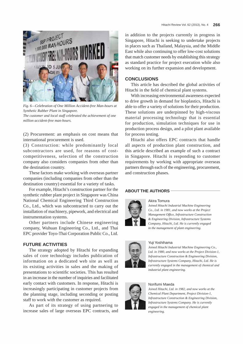
Hitachi Review Vol. 62 (2013), No. 4 266
in addition to the projects currently in progress in Singapore, Hitachi is seeking to undertake projects in places such as Thailand, Malaysia, and the Middle East while also continuing to offer low-cost solutions that match customer needs by establishing this strategy as standard practice for project execution while also working on its further expansion and development.
CONCLUSIONSThis article has described the global activities of
Hitachi in the field of chemical plant systems.With increasing environmental awareness expected
to drive growth in demand for bioplastics, Hitachi is able to offer a variety of solutions for their production. These solutions are underpinned by high-viscous material processing technology that is essential for production, simulation techniques for use in production process design, and a pilot plant available for process testing.
Hitachi also offers EPC contracts that handle all aspects of production plant construction, and this article described an example of such a contract in Singapore. Hitachi is responding to customer requirements by working with appropriate overseas partners through each of the engineering, procurement, and construction phases.
(2) Procurement: an emphasis on cost means that international procurement is used.(3) Construction: while predominantly local subcontractors are used, for reasons of cost-competitiveness, selection of the construction company also considers companies from other than the destination country.
These factors make working with overseas partner companies (including companies from other than the destination country) essential for a variety of tasks.
For example, Hitachi’s construction partner for the synthetic rubber plant project in Singapore was China national Chemical Engineering Third Construction Co., ltd., which was subcontracted to carry out the installation of machinery, pipework, and electrical and instrumentation systems.
other partners include Chinese engineering company, Wuhuan Engineering Co., ltd., and Thai EPC provider Toyo-Thai Corporation Public Co., ltd.
FUTURE ACTIVITIESThe strategy adopted by Hitachi for expanding
sales of core technology includes publication of information on a dedicated web site as well as its existing activities in sales and the making of presentations to scientific societies. This has resulted in an increase in the number of inquiries and facilitated early contact with customers. In response, Hitachi is increasingly participating in customer projects from the planning stage, including seconding or posting staff to work with the customer as required.
As part of its strategy of using partnering to increase sales of large overseas EPC contracts, and
Fig. 6—Celebration of One Million Accident-free Man-hours at Synthetic Rubber Plant in Singapore.The customer and local staff celebrated the achievement of one million accident-free man-hours.
Norifumi MaedaJoined Hitachi, Ltd. in 1982, and now works at the Chemical Plant Department, Project Division-1, Infrastructure Construction & Engineering Division, Infrastructure Systems Company. He is currently engaged in the management of chemical plant engineering.
Yuji YoshihamaJoined Hitachi Industrial Machine Engineering Co., Ltd. in 1980, and now works at the Project Division-1, Infrastructure Construction & Engineering Division, Infrastructure Systems Company, Hitachi, Ltd. He is currently engaged in the management of chemical and industrial plant engineering.
Akira TomuraJoined Hitachi Industrial Machine Engineering Co., Ltd. in 1981, and now works at the Project Management Office, Infrastructure Construction & Engineering Division, Infrastructure Systems Company, Hitachi, Ltd. He is currently engaged in the management of plant engineering.
ABOUT THE AUTHORS

Hitachi Review Vol. 62 (2013), No. 4 267
Advances in Biopharmaceutical and Vaccine Manufacturing Plants
Sei Murakami, Dr. Eng.
Haruo Suzuki
Keisuke Shibuya, Dr. Sc.
OVERVIEW: The development of innovative pharmaceuticals with potential for meeting unmet medical needs and vaccines that protect against infectious diseases is very important for ensuring people’s health and welfare. However, biopharmaceuticals and vaccines that make these developments possible are more easily affected by the production process than are chemically synthesized low-molecular-weight pharmaceuticals, and they demand a higher level of technology to manufacture reliably and efficiently. Hitachi is contributing to advances in biopharmaceutical and vaccine production technologies by working to improve the productivity and quality of pharmaceutical manufacturing.
INTRODUCTIONBIoPHARMACEUTICAlS (pharmaceuticals produced using biotechnology) such as monoclonal antibody drugs have attracted considerable interest in recent years to satisfy demand for treatments for currently untreatable diseases, and a series of large production plants have been built in different parts of the world. Meanwhile, although vaccines have already played an important role in protecting against infectious diseases, growing threats such as pandemic influenza or bioterrorism have prompted a major renewal of interest. In addition, a number of companies are working on therapeutic vaccines that take advantage of the immune system.
The following lists the challenges facing the production of these distinctive biopharmaceuticals and vaccines.(1) Compared to chemica l ly synthes ized pharmaceuticals, many of these drugs have a high molecular weight and variations in structure, and thus are limited in the extent to which their uniformity can be verified.(2) Problems such as allergies will arise unless impurities derived from cultured cells are adequately removed.(3) Small changes in the production process have the potential to cause changes such as to the quantity of impurities or the quality of the resulting product.(4) The construction of facilities needed for high-quality production is very expensive.
Considerable effort is being devoted to productivity and quality improvement in order to overcome these challenges.
This article gives an overview of biopharmaceutical and vaccine production technology and developments in the field, and describes the work Hitachi is doing to improve the productivity and quality of pharmaceutical production technology.
OVERVIEW OF BIOPHARMACEUTICALS PRODUCTION TECHNOLOGY AND ASSOCIATED DEVELOPMENTS
The production of biopharmaceuticals consists of a culture process, in which the desired product is produced by a biological reaction, and a recovery and purification process, in which contaminants are removed to purify the product.
Compared to chemically synthesized low-molecular-weight pharmaceuticals, biopharmaceuticals are inherently more expensive to produce for a number of reasons, including their long reaction times, low concentration of product, stringent sterility and cleanability requirements, and the use of expensive chromatography resin. This creates a strong need to improve productivity.
Improving the productivity of the culture and purification processes requires more than just increasing production quantities; what is also needed is to identify which components make up the largest part of production costs, such as the cost of materials, utilities, labor, or equipment, and then to make process improvements that reduce those costs. While the conventional approach to productivity improvement is to increase the concentration of product in the plant, in cases where raw materials such as the culture medium make up a large part of the cost, it is necessary to
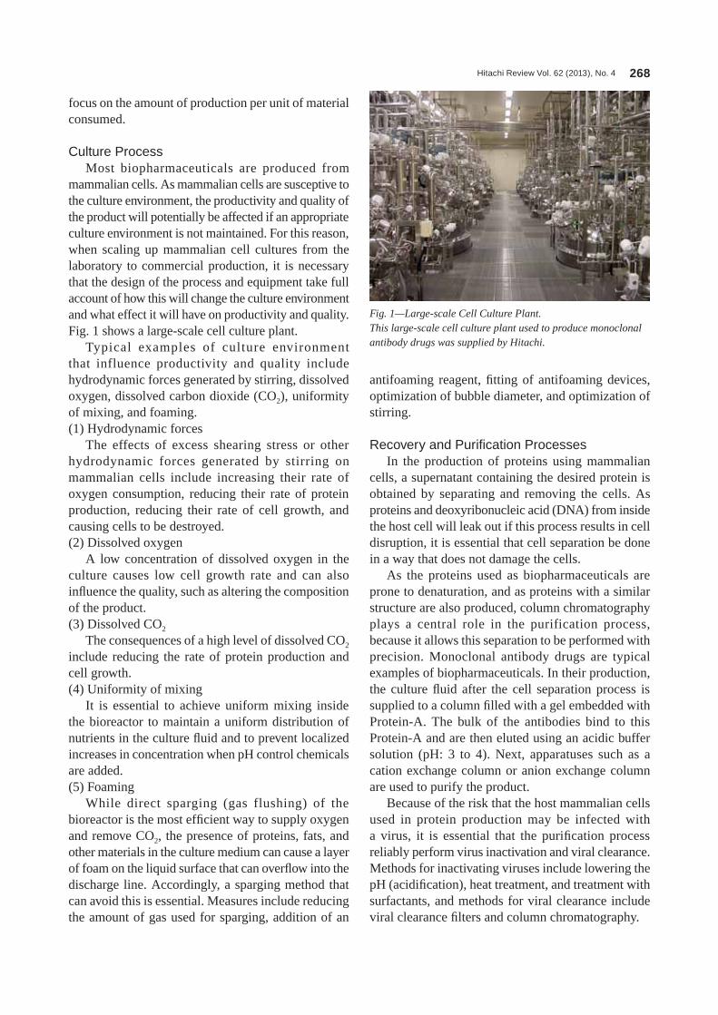
Hitachi Review Vol. 62 (2013), No. 4 268
focus on the amount of production per unit of material consumed.
Culture ProcessMost biopharmaceuticals are produced from
mammalian cells. As mammalian cells are susceptive to the culture environment, the productivity and quality of the product will potentially be affected if an appropriate culture environment is not maintained. For this reason, when scaling up mammalian cell cultures from the laboratory to commercial production, it is necessary that the design of the process and equipment take full account of how this will change the culture environment and what effect it will have on productivity and quality. Fig. 1 shows a large-scale cell culture plant.
Typical examples of culture environment that influence productivity and quality include hydrodynamic forces generated by stirring, dissolved oxygen, dissolved carbon dioxide (Co2), uniformity of mixing, and foaming.(1) Hydrodynamic forces
The effects of excess shearing stress or other hydrodynamic forces generated by stirring on mammalian cells include increasing their rate of oxygen consumption, reducing their rate of protein production, reducing their rate of cell growth, and causing cells to be destroyed.(2) Dissolved oxygen
A low concentration of dissolved oxygen in the culture causes low cell growth rate and can also influence the quality, such as altering the composition of the product.(3) Dissolved Co2
The consequences of a high level of dissolved Co2 include reducing the rate of protein production and cell growth.(4) Uniformity of mixing
It is essential to achieve uniform mixing inside the bioreactor to maintain a uniform distribution of nutrients in the culture fluid and to prevent localized increases in concentration when pH control chemicals are added.(5) Foaming
While direct sparging (gas flushing) of the bioreactor is the most efficient way to supply oxygen and remove Co2, the presence of proteins, fats, and other materials in the culture medium can cause a layer of foam on the liquid surface that can overflow into the discharge line. Accordingly, a sparging method that can avoid this is essential. Measures include reducing the amount of gas used for sparging, addition of an
antifoaming reagent, fitting of antifoaming devices, optimization of bubble diameter, and optimization of stirring.
Recovery and Purification ProcessesIn the production of proteins using mammalian
cells, a supernatant containing the desired protein is obtained by separating and removing the cells. As proteins and deoxyribonucleic acid (DnA) from inside the host cell will leak out if this process results in cell disruption, it is essential that cell separation be done in a way that does not damage the cells.
As the proteins used as biopharmaceuticals are prone to denaturation, and as proteins with a similar structure are also produced, column chromatography plays a central role in the purification process, because it allows this separation to be performed with precision. Monoclonal antibody drugs are typical examples of biopharmaceuticals. In their production, the culture fluid after the cell separation process is supplied to a column filled with a gel embedded with Protein-A. The bulk of the antibodies bind to this Protein-A and are then eluted using an acidic buffer solution (pH: 3 to 4). next, apparatuses such as a cation exchange column or anion exchange column are used to purify the product.
Because of the risk that the host mammalian cells used in protein production may be infected with a virus, it is essential that the purification process reliably perform virus inactivation and viral clearance. Methods for inactivating viruses include lowering the pH (acidification), heat treatment, and treatment with surfactants, and methods for viral clearance include viral clearance filters and column chromatography.
Fig. 1—Large-scale Cell Culture Plant.This large-scale cell culture plant used to produce monoclonal antibody drugs was supplied by Hitachi.

Advances in Biopharmaceutical and Vaccine Manufacturing Plants 269
gradient is established in the centrifuge rotor, then separation is performed based on the sedimentation coefficient and suspension density of the various compounds, including viral particles. next the viruses are inactivated and separation using an ultracentrifuge performed again. Fig. 2 shows an ultracentrifuge used for virus separation.(3) Chromatography
In processes that use genetic engineering to produce antigenic proteins directly, the proteins are separated out using chromatography in the same way as monoclonal antibody drugs and other biopharmaceuticals.
MEASURES FOR IMPROVING BIOPHARMACEUTICAL PRODUCTIVITY AND QUALITY
This section describes what Hitachi is doing to improve productivity and quality for the biopharmaceuticals described above.
Culture Process OptimizationIt is essential that the operation of the culture
process keeps hydrodynamic forces, gas exchange, mixing, and foaming in the bioreactor within appropriate ranges. The expression of the limits to
After undergoing these purification processes, the resulting product can achieve high purities of 99.9% or better, with cell-derived admixed protein levels of 5 ng/mg or less, cell-derived DnA levels of 10 pg/mg or less, and pyrogen levels of 0.005 endotoxin units (EU)/mg or less. However, this also means that the bulk of the target protein produced by the culture process is lost in processing.
OVERVIEW OF VACCINE PRODUCTION TECHNOLOGY AND ASSOCIATED DEVELOPMENTS
Use of mammalian cell cultures for the production of vaccines has been on the rise since its use for rabies vaccine in the 1970s. In recent years, it has been used for the production of vaccines for diseases such as hepatitis A, Japanese encephalitis, polio, and influenza. Vaccine production can also be spilt into a culture process and recovery/purification process.
Culture ProcessTo produce a vaccine in large quantities as soon
as possible after a new form of influenza appears, it is necessary to use cell-culture-based manufacturing systems rather than the egg-based manufacturing systems used in the past. After multiplying cells in the culture process, the cells are infected with the virus, which is allowed to multiply, and then the antigen that forms the basis of the vaccine is harvested. Methods that use genetically engineered cells to produce the antigenic protein directly, in the same way as a biopharmaceutical, have also been developed.
Recovery and Purification ProcessesIn the vaccine recovery and purification processes,
the cells and contaminants are first removed from the culture fluid to obtain the supernatant containing the virus. This is then subject to virus inactivation, destruction, concentration, and filtering.(1) Cell separation
Removal of cells and cell debris from the culture fluid is typically performed using a continuous-flow centrifuge operating at about 12,000 g.(2) Virus separation
Removal of viruses from the recovered fluid requires use of an ultracentrifuge that generates an even higher centrifugal force (about 110,000 g) than that used for cell separation. Furthermore, centrifugal separation based on sucrose density gradient is performed to achieve an even higher degree of precise fractionation. First a sucrose density
Fig. 2—Ultracentrifuge Used for Virus Separation.This ultracentrifuge for virus separation made by Hitachi Koki Co., Ltd. operates at approximately 110,000 G to separate viruses from the recovered fluid.
Photograph courtesy of Hitachi Koki Co., ltd.

Hitachi Review Vol. 62 (2013), No. 4 270
ModularizationPlants with an important public safety role, such
as those used to produce pandemic vaccines, need to improve the quality of their products and they must be able to get supply systems in place quickly using rapid construction practices. To achieve this, Hitachi makes extensive use of modularization design and construction techniques, in which tanks and piping are prefabricated at the factory, and has shortened on-site construction times (see Fig. 3).
AutomationTo maintain product quality, the production
processes for biopharmaceuticals and vaccines require sophisticated sterilization and cleaning. large biopharmaceutical plants need to use distributed control systems (DCSs) to ensure that they can control their 1,000 or more valves correctly and avoid misoperation. For the development of control software for these systems, there is a need to standardize process flow and control software to reduce design workloads, and to establish and verify operating practices based on sterilization and cleaning mechanisms that suit the plant’s systems. Fig. 4 shows example DCS screens (graphic display and block diagram of process flow) from a large biopharmaceutical plant.
CONCLUSIONSBiopharmaceuticals and vaccines are well
recognized for their potential in treating incurable diseases for which conventional low-molecular-weight pharmaceuticals produced by chemical synthesis are ineffective, and for preventing infectious diseases. However, they also face challenges such as high
these ranges in terms of the stirring speed and sparging rate is called the “scale-up window”(1). As the scale of a culture becomes larger, the scale-up window becomes progressively narrower until it disappears entirely above the upper limit on scale-up(2).
For large scale production, it is important that the process design make this scale-up window as broad as possible, and achieving this requires that optimization be performed through a large number of shapes and operating conditions. Use of computational fluid dynamics (CFD) to analyze bioreactor performance is an effective way of doing this. Having already applied this technique at many commercial plants, Hitachi has established biological, chemical, and physical models, input conditions, and calculation methods, and has also conducted testing. Meanwhile, Hitachi has a pilot plant for evaluating the growth characteristics of cell cultures for biopharmaceuticals and vaccine production that can also be used for tasks such as verifying CFD results, determining growth characteristics when using the customer’s cells, and optimizing culture conditions.
Culture Process Quality ImprovementQuality by design (QbD) is a technique adopted
to modernize quality management systems for pharmaceuticals. It is a systematic development methodology based on verified science and quality risk management that specifies targets in advance and emphasizes process management and understanding of the product and process(3). QbD is already used for chemically synthesized low-molecular-weight pharmaceuticals, and it is also being applied to biopharmaceuticals with complex molecular structures and production processes. Risk assessment in QbD uses sophisticated statistical methods to identify relationships between the process and quality attributes. This information is then used for establishing production procedures. These methods treat the culture and purification processes as black boxes. However, if it is possible to determine how the culture environment affects the productivity and quality of the product in terms of the cell metabolic mechanisms, tasks such as predicting effects and identifying the causes of deviations can be performed with greater precision and efficiency than when the process is treated as a black box. While metabolic analysis methods have been widely used for microorganisms with simple metabolic reactions in the past, Hitachi has now started applying metabolic models to mammalian cells with complex metabolic reactions(4).
Fig. 3—Three-dimensional Computer-aided Design Image of Tank and Pipe Module.Construction time is shortened by prefabricating modules in the factory and delivering them to the site for installation.
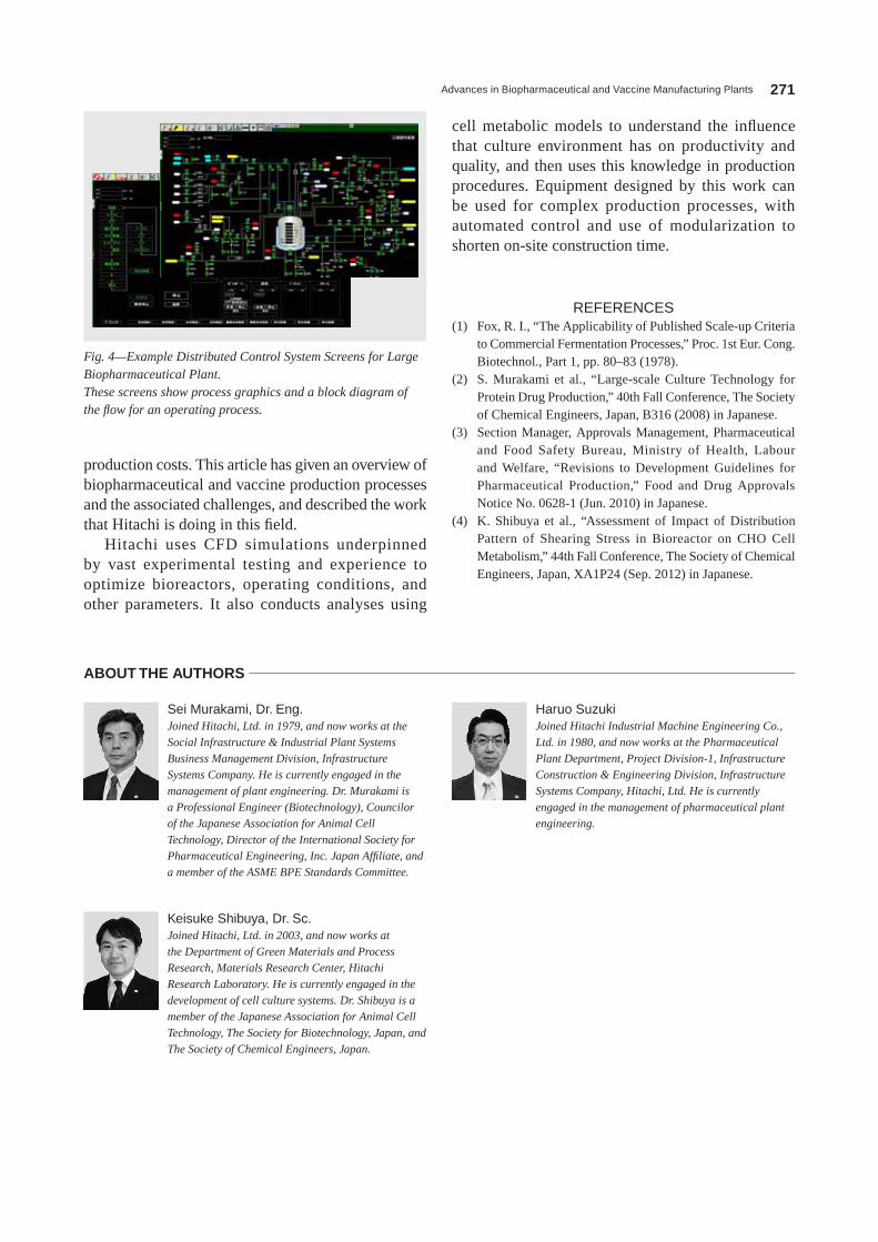
Advances in Biopharmaceutical and Vaccine Manufacturing Plants 271
cell metabolic models to understand the influence that culture environment has on productivity and quality, and then uses this knowledge in production procedures. Equipment designed by this work can be used for complex production processes, with automated control and use of modularization to shorten on-site construction time.
REFERENCES(1) Fox, R. I., “The Applicability of Published Scale-up Criteria
to Commercial Fermentation Processes,” Proc. 1st Eur. Cong. Biotechnol., Part 1, pp. 80–83 (1978).
(2) S. Murakami et al., “large-scale Culture Technology for Protein Drug Production,” 40th Fall Conference, The Society of Chemical Engineers, Japan, B316 (2008) in Japanese.
(3) Section Manager, Approvals Management, Pharmaceutical and Food Safety Bureau, Ministry of Health, labour and Welfare, “Revisions to Development guidelines for Pharmaceutical Production,” Food and Drug Approvals notice no. 0628-1 (Jun. 2010) in Japanese.
(4) K. Shibuya et al., “Assessment of Impact of Distribution Pattern of Shearing Stress in Bioreactor on CHo Cell Metabolism,” 44th Fall Conference, The Society of Chemical Engineers, Japan, XA1P24 (Sep. 2012) in Japanese.
production costs. This article has given an overview of biopharmaceutical and vaccine production processes and the associated challenges, and described the work that Hitachi is doing in this field.
Hitachi uses CFD simulations underpinned by vast experimental testing and experience to optimize bioreactors, operating conditions, and other parameters. It also conducts analyses using
Fig. 4—Example Distributed Control System Screens for Large Biopharmaceutical Plant.These screens show process graphics and a block diagram of the flow for an operating process.
Haruo SuzukiJoined Hitachi Industrial Machine Engineering Co., Ltd. in 1980, and now works at the Pharmaceutical
Plant Department, Project Division-1, Infrastructure Construction & Engineering Division, Infrastructure Systems Company, Hitachi, Ltd. He is currently engaged in the management of pharmaceutical plant engineering.
Sei Murakami, Dr. Eng.Joined Hitachi, Ltd. in 1979, and now works at the Social Infrastructure & Industrial Plant Systems
Business Management Division, Infrastructure Systems Company. He is currently engaged in the management of plant engineering. Dr. Murakami is a Professional Engineer (Biotechnology), Councilor of the Japanese Association for Animal Cell Technology, Director of the International Society for Pharmaceutical Engineering, Inc. Japan Affiliate, and a member of the ASME BPE Standards Committee.
Keisuke Shibuya, Dr. Sc.Joined Hitachi, Ltd. in 2003, and now works at the Department of Green Materials and Process Research, Materials Research Center, Hitachi Research Laboratory. He is currently engaged in the development of cell culture systems. Dr. Shibuya is a member of the Japanese Association for Animal Cell Technology, The Society for Biotechnology, Japan, and The Society of Chemical Engineers, Japan.
ABOUT THE AUTHORS
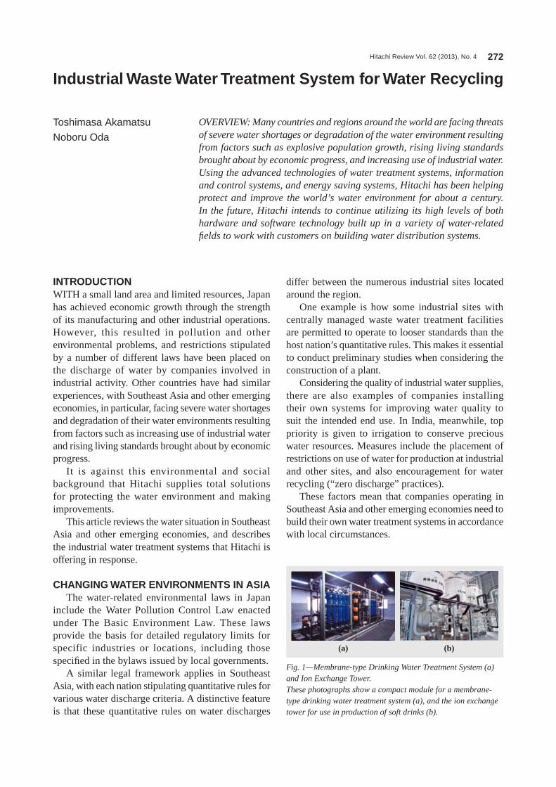
Hitachi Review Vol. 62 (2013), No. 4 272
Industrial Waste Water Treatment System for Water Recycling
Toshimasa Akamatsu
Noboru Oda
OVERVIEW: Many countries and regions around the world are facing threats of severe water shortages or degradation of the water environment resulting from factors such as explosive population growth, rising living standards brought about by economic progress, and increasing use of industrial water. Using the advanced technologies of water treatment systems, information and control systems, and energy saving systems, Hitachi has been helping protect and improve the world’s water environment for about a century. In the future, Hitachi intends to continue utilizing its high levels of both hardware and software technology built up in a variety of water-related fields to work with customers on building water distribution systems.
INTRODUCTIONWITH a small land area and limited resources, Japan has achieved economic growth through the strength of its manufacturing and other industrial operations. However, this resulted in pollution and other environmental problems, and restrictions stipulated by a number of different laws have been placed on the discharge of water by companies involved in industrial activity. other countries have had similar experiences, with Southeast Asia and other emerging economies, in particular, facing severe water shortages and degradation of their water environments resulting from factors such as increasing use of industrial water and rising living standards brought about by economic progress.
It is against this environmental and social background that Hitachi supplies total solutions for protecting the water environment and making improvements.
This article reviews the water situation in Southeast Asia and other emerging economies, and describes the industrial water treatment systems that Hitachi is offering in response.
CHANGING WATER ENVIRONMENTS IN ASIAThe water-related environmental laws in Japan
include the Water Pollution Control law enacted under The Basic Environment law. These laws provide the basis for detailed regulatory limits for specific industries or locations, including those specified in the bylaws issued by local governments.
A similar legal framework applies in Southeast Asia, with each nation stipulating quantitative rules for various water discharge criteria. A distinctive feature is that these quantitative rules on water discharges
differ between the numerous industrial sites located around the region.
one example is how some industrial sites with centrally managed waste water treatment facilities are permitted to operate to looser standards than the host nation’s quantitative rules. This makes it essential to conduct preliminary studies when considering the construction of a plant.
Considering the quality of industrial water supplies, there are also examples of companies installing their own systems for improving water quality to suit the intended end use. In India, meanwhile, top priority is given to irrigation to conserve precious water resources. Measures include the placement of restrictions on use of water for production at industrial and other sites, and also encouragement for water recycling (“zero discharge” practices).
These factors mean that companies operating in Southeast Asia and other emerging economies need to build their own water treatment systems in accordance with local circumstances.
Fig. 1—Membrane-type Drinking Water Treatment System (a) and Ion Exchange Tower.These photographs show a compact module for a membrane-type drinking water treatment system (a), and the ion exchange tower for use in production of soft drinks (b).
(a) (b)
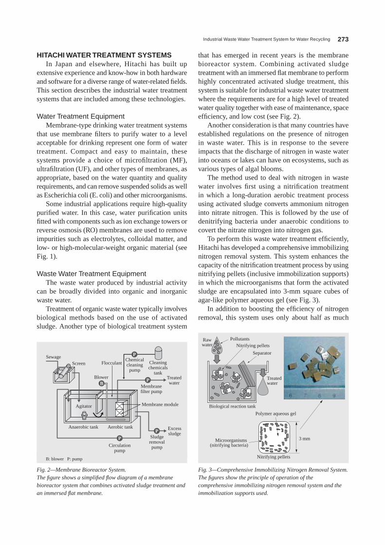
Industrial Waste Water Treatment System for Water Recycling 273
HITACHI WATER TREATMENT SYSTEMSIn Japan and elsewhere, Hitachi has built up
extensive experience and know-how in both hardware and software for a diverse range of water-related fields. This section describes the industrial water treatment systems that are included among these technologies.
Water Treatment EquipmentMembrane-type drinking water treatment systems
that use membrane filters to purify water to a level acceptable for drinking represent one form of water treatment. Compact and easy to maintain, these systems provide a choice of microfiltration (MF), ultrafiltration (UF), and other types of membranes, as appropriate, based on the water quantity and quality requirements, and can remove suspended solids as well as Escherichia coli (E. coli) and other microorganisms.
Some industrial applications require high-quality purified water. In this case, water purification units fitted with components such as ion exchange towers or reverse osmosis (Ro) membranes are used to remove impurities such as electrolytes, colloidal matter, and low- or high-molecular-weight organic material (see Fig. 1).
Waste Water Treatment EquipmentThe waste water produced by industrial activity
can be broadly divided into organic and inorganic waste water.
Treatment of organic waste water typically involves biological methods based on the use of activated sludge. Another type of biological treatment system
that has emerged in recent years is the membrane bioreactor system. Combining activated sludge treatment with an immersed flat membrane to perform highly concentrated activated sludge treatment, this system is suitable for industrial waste water treatment where the requirements are for a high level of treated water quality together with ease of maintenance, space efficiency, and low cost (see Fig. 2).
Another consideration is that many countries have established regulations on the presence of nitrogen in waste water. This is in response to the severe impacts that the discharge of nitrogen in waste water into oceans or lakes can have on ecosystems, such as various types of algal blooms.
The method used to deal with nitrogen in waste water involves first using a nitrification treatment in which a long-duration aerobic treatment process using activated sludge converts ammonium nitrogen into nitrate nitrogen. This is followed by the use of denitrifying bacteria under anaerobic conditions to covert the nitrate nitrogen into nitrogen gas.
To perform this waste water treatment efficiently, Hitachi has developed a comprehensive immobilizing nitrogen removal system. This system enhances the capacity of the nitrification treatment process by using nitrifying pellets (inclusive immobilization supports) in which the microorganisms that form the activated sludge are encapsulated into 3-mm square cubes of agar-like polymer aqueous gel (see Fig. 3).
In addition to boosting the efficiency of nitrogen removal, this system uses only about half as much
B
P
P
P
P
SewageScreen Flocculant
Blower
Chemicalcleaning
pump
Cleaningchemicals
tank
Agitator
Anaerobic tank Aerobic tank
Circulationpump
Sludgeremovalpump
Excesssludge
Membranefilter pump
Membrane module
Treatedwater
B: blower P: pump
Fig. 2—Membrane Bioreactor System.The figure shows a simplified flow diagram of a membrane bioreactor system that combines activated sludge treatment and an immersed flat membrane.
Fig. 3—Comprehensive Immobilizing Nitrogen Removal System.The figures show the principle of operation of the comprehensive immobilizing nitrogen removal system and the immobilization supports used.
3 mm
Rawwater
PollutantsNitrifying pellets
Nitrifying pellets
Separator
Treatedwater
Biological reaction tank
Polymer aqueous gel
Microorganisms (nitrifying bacteria)

Hitachi Review Vol. 62 (2013), No. 4 274
one distinctive technology of Hitachi is its advanced fluorine treatment device (see Fig. 5). This device converts the residual fluorine in water treated using flocculation that contains hydrofluoric acid to apatite, and then precipitates it on the surface of a crystallized material. It uses an expanded-layer reactor structure that makes it simpler, easier to maintain, and less costly than existing two-stage coagulation sedimentation devices (see Fig. 6).
Equipment for Water ReuseHitachi has for some time been developing
systems that combine Ro membranes with membrane bioreactor systems, and that are targeted particularly at regions that suffer from water shortages. These systems
space as previous methods. Hitachi has had extensive experience with this technology over many years (see Fig. 4). Hitachi is now developing a system for treating waste water with a high nitrogen concentration that uses inclusive immobilization supports embedded with anaerobic ammonium oxidation (AnAMMoX) bacteria capable of removing nitrogen directly from ammonium nitrogen. Because this inclusive immobilization technology also has the potential for deployment in other applications, Hitachi is proceeding with further research and development, including its use for the removal of other restricted substances.
In the case of inorganic waste water, on the other hand, it is necessary to choose a treatment method that suits the substance to be removed.
Fig. 6—Advanced Fluorine Treatment Device.This advanced fluorine treatment device is based on a precipitation reaction.
P
B
Primarytreated water
Treatedwater
Submergibleaerator
Circulated fluid
Denitrification tank Nitrification tank
Final sedimentation tank
Returned sludge
Nitrifying pellets
Fig. 4—System Flow Diagram of Comprehensive Immobilizing Nitrogen Removal System.This shows the standard configuration of a comprehensive immobilizing nitrogen removal system.
Fig. 5—Principle of Operation of Advanced Fluorine Treatment Device.The diagram shows the principle of operation of this advanced fluorine treatment technology based on a precipitation reaction.
Circulated water
Treated water
Excess crystallizedmaterial (drained periodically)
Discharge (water flocculatedusing hydrated lime)
FluorinePhosphorus Calcium
Crystallizedmaterial
CrystallizedmaterialPhosphorous-based
reagent
Fluorapatite precipitateson the surface of
the crystallized material
5Ca+3PO4+F Ca5(PO4)3F(Fluorapatite)
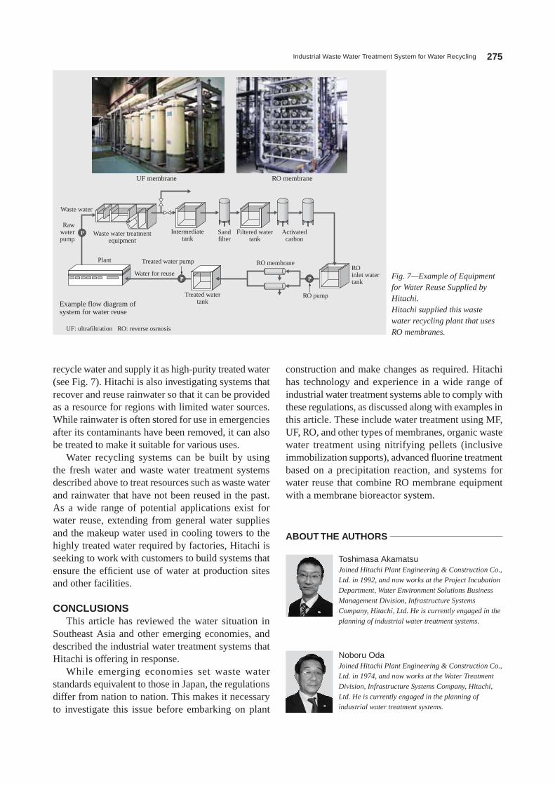
Industrial Waste Water Treatment System for Water Recycling 275
construction and make changes as required. Hitachi has technology and experience in a wide range of industrial water treatment systems able to comply with these regulations, as discussed along with examples in this article. These include water treatment using MF, UF, Ro, and other types of membranes, organic waste water treatment using nitrifying pellets (inclusive immobilization supports), advanced fluorine treatment based on a precipitation reaction, and systems for water reuse that combine Ro membrane equipment with a membrane bioreactor system.
recycle water and supply it as high-purity treated water (see Fig. 7). Hitachi is also investigating systems that recover and reuse rainwater so that it can be provided as a resource for regions with limited water sources. While rainwater is often stored for use in emergencies after its contaminants have been removed, it can also be treated to make it suitable for various uses.
Water recycling systems can be built by using the fresh water and waste water treatment systems described above to treat resources such as waste water and rainwater that have not been reused in the past. As a wide range of potential applications exist for water reuse, extending from general water supplies and the makeup water used in cooling towers to the highly treated water required by factories, Hitachi is seeking to work with customers to build systems that ensure the efficient use of water at production sites and other facilities.
CONCLUSIONSThis article has reviewed the water situation in
Southeast Asia and other emerging economies, and described the industrial water treatment systems that Hitachi is offering in response.
While emerging economies set waste water standards equivalent to those in Japan, the regulations differ from nation to nation. This makes it necessary to investigate this issue before embarking on plant
Toshimasa AkamatsuJoined Hitachi Plant Engineering & Construction Co., Ltd. in 1992, and now works at the Project Incubation Department, Water Environment Solutions Business Management Division, Infrastructure Systems Company, Hitachi, Ltd. He is currently engaged in the planning of industrial water treatment systems.
ABOUT THE AUTHORS
Noboru OdaJoined Hitachi Plant Engineering & Construction Co., Ltd. in 1974, and now works at the Water Treatment Division, Infrastructure Systems Company, Hitachi, Ltd. He is currently engaged in the planning of industrial water treatment systems.
PP
P
UF membrane
Rawwaterpump
Intermediatetank
Sandfilter
Activatedcarbon
Plant
Water for reuse
Treated water pump
Example flow diagram ofsystem for water reuse
RO membrane
RO pump
ROinlet watertank
Treated watertank
Filtered watertank
Waste water treatmentequipment
Waste water
RO membrane
UF: ultrafiltration Ro: reverse osmosis
Fig. 7—Example of Equipment for Water Reuse Supplied by Hitachi.Hitachi supplied this waste water recycling plant that uses RO membranes.
Hitachi Review Vol. 62 (2013), No. 4 276
Plant Maintenance Services and Application of ICT
Shigeru Toida
Fumio Hatori
Mitsuhiro Takemoto
OVERVIEW: After a plant is constructed, the plant’s owners need to manage not only production, but also the maintenance of equipment that requires specialist knowledge and experience. The obstacles to achieving this include a shortage of maintenance technicians, rising maintenance costs due to the aging of industrial equipment, and the difficultly of training maintenance staff. Hitachi is drawing on its plant construction activities to strengthen its plant maintenance management business and work together with its customers over all operations, from plant construction to after-sales service. Key factors in achieving this are the use of ICT and the service infrastructure that supports plant maintenance.
INTRODUCTIONTHE maintenance of industrial equipment frequently requires specialist knowledge and experience. Currently, however, the obstacles to achieving this include a shortage of maintenance technicians, rising maintenance costs due to the aging of industrial equipment(1), a lack of maintenance and managerial know-how and experience among maintenance staff, and staff training issues such as problem solving skills.
given this background, there is a growing international demand for strengthening after-sales services for the operation and maintenance of equipment after plant construction.
This article describes the challenges facing plant maintenance and after-sales services, the infrastructure for supplying services to plants, and the use of information and communication technology (ICT).
CHALLENGES FACING PLANT MAINTENANCE AND AFTER-SALES SERVICES
In broad terms, the operation and maintenance of equipment in order to keep up with production plans face two major challenges. These are the operational status monitoring of equipment, which is done to avoid disruption caused by faults, and facilities management, which is done to keep equipment working correctly.
Dealing with these two challenges requires not only that inspections be conducted in accordance with detailed schedules, but also the undertaking of preventive maintenance that draws on the sorts of experience and awareness that cannot be captured in a manual, and also improvement work for dealing with non-compliance or other problems. This in turn requires the involvement of staff, including
dealing with new issues that arise due to the aging of equipment. Unfortunately, it is difficult to maintain and improve standards in this area merely through the education and training of inexperienced staff.
CHALLENGES FOR AFTER-SALES SERVICES
After-sales services provided by maintenance companies in developed economies involve service personnel proposing solutions, and performing repairs and upgrades based on the results of “patrol” inspections. Service personnel have a thorough understanding of the customer’s equipment and undertake inspection, repairs, and upgrades with a sense of unity with the customer. However, with technical staff aging at both maintenance companies and their customers, and with growing price competition bringing down the costs of maintaining equipment, the task of ensuring the reliable operation and maintenance of production equipment currently faces a difficult environment.
At plants in emerging economies, meanwhile, factors such as traffic congestion make the performance of on-site patrol inspections difficult. In the case of businesses that deal only in mass production equipment, it is possible to establish service companies in each market and provide after-sales services for equipment in a similar way to developed economies. When handling maintenance for entire plants or for made-to-order equipment, on the other hand, this approach to after-sales services is not practical and also places a heavy burden on the plant owners.
These circumstances required the timely collection of the ever-changing information from the plant and advance planning of activities. The next section
Plant Maintenance Services and Application of ICT 277
describes the measures and activities being undertaken by Hitachi.
ESTABLISHMENT OF INFRASTRUCTURE FOR PLANT MAINTENANCE SERVICES
Because plant construction companies work with the customer throughout a construction project, they are in a position to understand such things as their operational philosophies and the thinking behind their business plans. During this time, they also have a thorough understanding of the equipment at the plant, such as details of piping and wiring layouts. In other words, a feature of plant construction companies is their ability to support the customer’s operation and maintenance by utilizing this understanding and information.
To take advantage of this feature of the plant construction sector, it is necessary to establish a customer support infrastructure in the post-construction period that brings together, close to the customer’s plant, all the companies involved with the equipment. Also required are the engineering capabilities for repairs and enhancements.
As a plant construction contractor, Hitachi seeks to strengthen not only customers’ plant construction but also their after-sales services, so as to provide them with ongoing support after construction completes.
Establishment of Service Infrastructure through Formation of the Hitachi Subsidiary
When constructing a plant in a particular country, the Hitachi subsidiary in that country works with a wide range of local companies. By collaborating with companies involved in the construction who are familiar with the workings of the plant, Hitachi is able to ensure the reliability, shorten the work period, and minimize the cost of post-construction maintenance. It has set up subsidiaries in China, the Republic of Singapore, the Republic of Indonesia, the Socialist Republic of Viet nam, the Kingdom of Thailand, Malaysia, and the Republic of the Philippines to establish the infrastructure for supporting customers throughout the lifecycle from construction to services. It has also set up service satellite operations located close to major industrial complexes in various countries that act as bases for enhancing customer services.
Use of ICT in ServicesRemote monitoring has been in use for some
time as a means of using ICT to monitor equipment
operation, and other developments range from simple sensors through to technologies that incorporate graphics or acoustic information. However, because sensor data alone is insufficient for plant-wide monitoring, it remains standard practice to conduct on-site patrol inspections. An emerging technology for this purpose is the use of portable devices to eliminate the distance between the site and the monitoring room.
In the case of facilities management, activities include considering maintenance plans that cover all equipment; management of inspection, fault, and other records all the way back to the time of construction; coordination of inspection timings with production; and spare parts management. Recently, ICT has started to be adopted for purposes such as the introduction of common management practices across Japan and other countries, and integration with applications such as enterprise asset management (EAM) that deal with asset and personnel management.
The need to build a framework for supporting maintenance services that utilizes ICT is recognized as an urgent task for meeting the demand for plant after-sales services. Hitachi is commercializing the plant maintenance systems described below.
SUPPORT TECHNOLOGY FOR CLOUD SERVICES
Cloud computing is the general term for a computer technology for delivering software for use over the Internet without the user being aware of where the servers or other ICT hardware is located(2), (3). In this article, the term “cloud services” is used to indicate services that operate via a support system for maintenance, after-sales services, and similar business activities that has been built on the use of cloud computing.
Fig. 1 shows an overview of cloud services for equipment maintenance.
Application to Operational MonitoringIn the past, activities such as product repairs and
replacements or dealing with faults were performed in response to on-site patrol inspections by service personnel or reports from the customer. Meanwhile, the sort of remote monitoring undertaken in the past involved installing monitoring devices to collect operational data from the product to determine its condition and other information such as parts usage.
Cloud services are able to take advantage of the possession of high-capacity storage devices to record and utilize the stream of constantly changing control
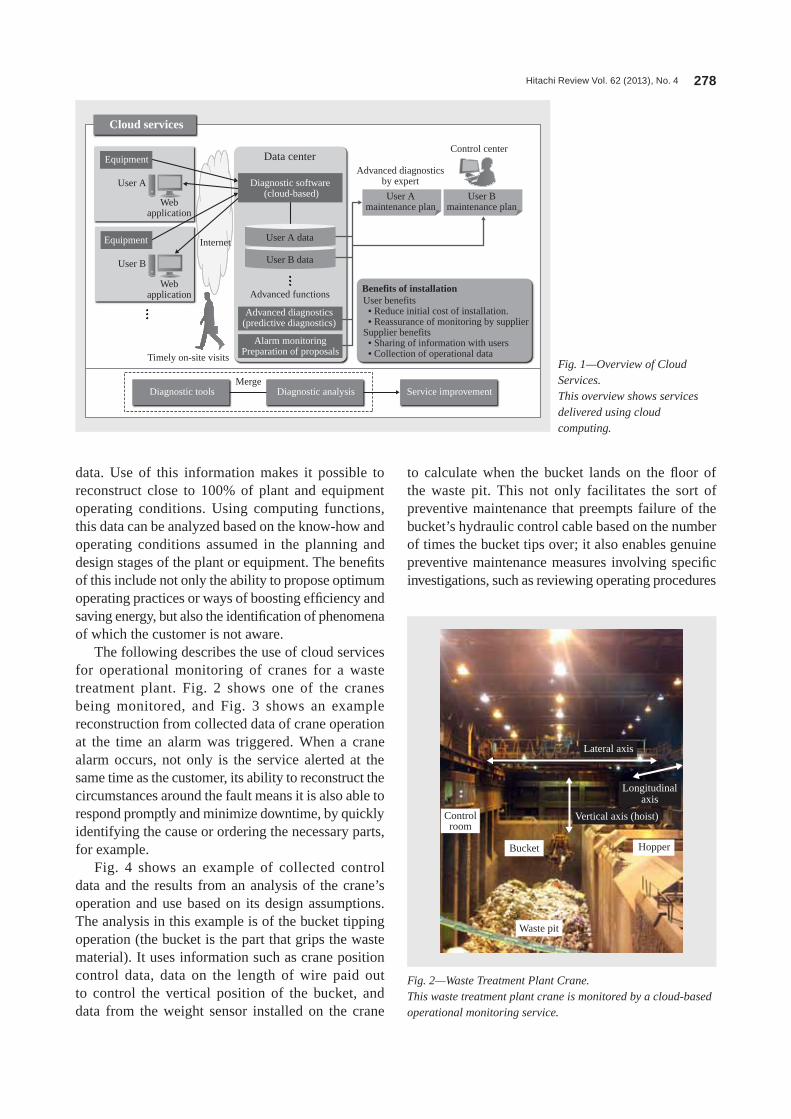
Hitachi Review Vol. 62 (2013), No. 4 278
to calculate when the bucket lands on the floor of the waste pit. This not only facilitates the sort of preventive maintenance that preempts failure of the bucket’s hydraulic control cable based on the number of times the bucket tips over; it also enables genuine preventive maintenance measures involving specific investigations, such as reviewing operating procedures
data. Use of this information makes it possible to reconstruct close to 100% of plant and equipment operating conditions. Using computing functions, this data can be analyzed based on the know-how and operating conditions assumed in the planning and design stages of the plant or equipment. The benefits of this include not only the ability to propose optimum operating practices or ways of boosting efficiency and saving energy, but also the identification of phenomena of which the customer is not aware.
The following describes the use of cloud services for operational monitoring of cranes for a waste treatment plant. Fig. 2 shows one of the cranes being monitored, and Fig. 3 shows an example reconstruction from collected data of crane operation at the time an alarm was triggered. When a crane alarm occurs, not only is the service alerted at the same time as the customer, its ability to reconstruct the circumstances around the fault means it is also able to respond promptly and minimize downtime, by quickly identifying the cause or ordering the necessary parts, for example.
Fig. 4 shows an example of collected control data and the results from an analysis of the crane’s operation and use based on its design assumptions. The analysis in this example is of the bucket tipping operation (the bucket is the part that grips the waste material). It uses information such as crane position control data, data on the length of wire paid out to control the vertical position of the bucket, and data from the weight sensor installed on the crane
Fig. 2—Waste Treatment Plant Crane.This waste treatment plant crane is monitored by a cloud-based operational monitoring service.
Vertical axis (hoist)
Lateral axis
Longitudinalaxis
Controlroom
Bucket Hopper
Waste pit
Fig. 1—Overview of Cloud Services.This overview shows services delivered using cloud computing.
Internet User A data
User B data
Advanced functions
User A
Data center
User B
Webapplication
Webapplication
Timely on-site visits
Merge
Advanced diagnosticsby expert
Control center
User Amaintenance plan
User Bmaintenance plan
Benefits of installation
Cloud services
Equipment
Diagnostic software (cloud-based)
Advanced diagnostics(predictive diagnostics)
Alarm monitoringPreparation of proposals
Diagnostic tools Diagnostic analysis Service improvement
Equipment
User benefits • Reduce initial cost of installation. • Reassurance of monitoring by supplierSupplier benefits • Sharing of information with users • Collection of operational data

Plant Maintenance Services and Application of ICT 279
sensors. This ability to generate various types of information from existing data without installing new devices for information capture is one of the major attractions of cloud computing.
at the waste treatment plant to prevent tipping from occurring by analyzing trends such as locations where tipping occurs frequently.
Fig. 5 shows the height of the waste pile in the waste pit. It is possible to calculate the heights of the waste pile at different times from information on the weight of the waste and the crane’s longitudinal, lateral, and vertical positions without needing to install any new imaging equipment or height measurement
Fig. 3—Example Reconstruction of Fault.Collected data can be used to reconstruct the circumstances at the time an alarm was triggered.
-6
-5
-4
-3
-2
-1
0
1
2
3
4
5
0
5,000
10,000
15,000
20,000
25,000
30,000
35,000
40,0007:
03:2
07:
03:3
07:
03:4
07:
03:5
07:
04:0
07:
04:1
07:
04:2
07:
04:3
07:
04:4
07:
04:5
07:
05:0
07:
05:1
07:
05:2
07:
05:3
07:
05:4
07:
05:5
07:
06:0
07:
06:1
07:
06:2
07:
06:3
07:
06:4
07:
06:5
07:
07:0
07:
07:1
07:
07:2
07:
07:3
07:
07:4
07:
07:5
07:
08:0
07:
08:1
0
A time-series reconstruction of crane operation is produced from mass data andlongitudinal, lateral, and vertical positions.
Waste pile heightWaste, 2.5 t
Lowerbucket
Contact with floor
Contactwith floor
Waste, 2 t
Bucketempty
Identify the operation that caused the breakdown by verifying the crane operation around the time it occurred.
Interpretation of circumstances at time of alarm: while repositioning waste, the alarm occurred with the hoistat a position of between 31,752 mm and 32,158 mm, while lowering the bucket at the same time as
moving in both the longitudinal and lateral directions in preparation for picking up another load of waste.
Vertical position Longitudinal position
Alarm Recovery
Loa
d (t
)
Posi
tion
(mm
)
Lateral position Weight
Fig. 4—Example Analysis of Crane Operation.The graph plots the positions at which the crane bucket (the part that grips the waste material) lands on the floor. These positions are calculated from data on the crane’s position in each axis. The information can be used to improve operating practices.
0 5,000 10,000 15,000 20,0000
2,000
4,000
6,000
8,000
10,000
12,000
14,000
16,000
25,000 30,000 35,000Longitudinal position (mm)
Lat
eral
pos
ition
(m
m)
Fig. 5—Example Calculation of Waste Pile Height from Crane Position Data.The height of waste piled in the waste pit can be calculated.
25
20
15
10
5
0
D
C
B
A5
1015
Was
te p
ile h
eigh
t (m
)
Lateral location
Longitudinal location
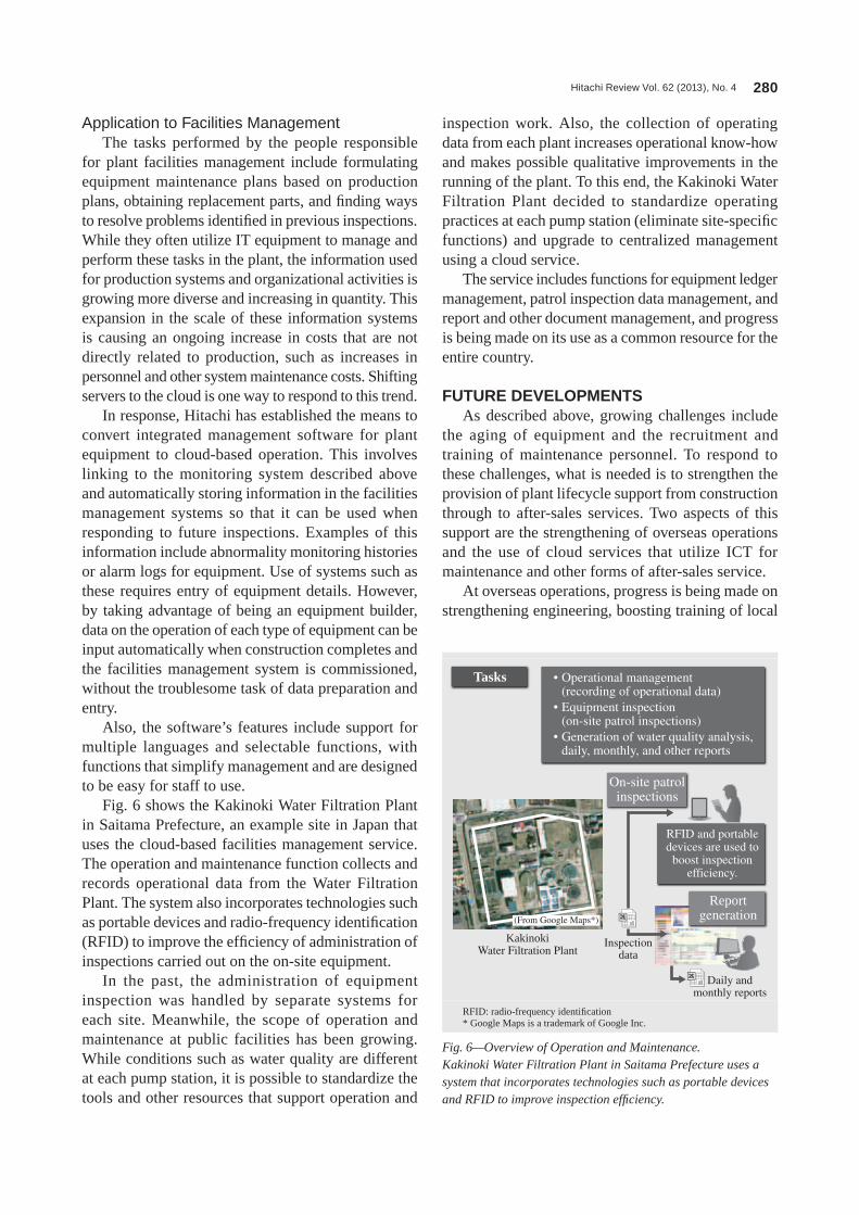
Hitachi Review Vol. 62 (2013), No. 4 280
inspection work. Also, the collection of operating data from each plant increases operational know-how and makes possible qualitative improvements in the running of the plant. To this end, the Kakinoki Water Filtration Plant decided to standardize operating practices at each pump station (eliminate site-specific functions) and upgrade to centralized management using a cloud service.
The service includes functions for equipment ledger management, patrol inspection data management, and report and other document management, and progress is being made on its use as a common resource for the entire country.
FUTURE DEVELOPMENTSAs described above, growing challenges include
the aging of equipment and the recruitment and training of maintenance personnel. To respond to these challenges, what is needed is to strengthen the provision of plant lifecycle support from construction through to after-sales services. Two aspects of this support are the strengthening of overseas operations and the use of cloud services that utilize ICT for maintenance and other forms of after-sales service.
At overseas operations, progress is being made on strengthening engineering, boosting training of local
Application to Facilities ManagementThe tasks performed by the people responsible
for plant facilities management include formulating equipment maintenance plans based on production plans, obtaining replacement parts, and finding ways to resolve problems identified in previous inspections. While they often utilize IT equipment to manage and perform these tasks in the plant, the information used for production systems and organizational activities is growing more diverse and increasing in quantity. This expansion in the scale of these information systems is causing an ongoing increase in costs that are not directly related to production, such as increases in personnel and other system maintenance costs. Shifting servers to the cloud is one way to respond to this trend.
In response, Hitachi has established the means to convert integrated management software for plant equipment to cloud-based operation. This involves linking to the monitoring system described above and automatically storing information in the facilities management systems so that it can be used when responding to future inspections. Examples of this information include abnormality monitoring histories or alarm logs for equipment. Use of systems such as these requires entry of equipment details. However, by taking advantage of being an equipment builder, data on the operation of each type of equipment can be input automatically when construction completes and the facilities management system is commissioned, without the troublesome task of data preparation and entry.
Also, the software’s features include support for multiple languages and selectable functions, with functions that simplify management and are designed to be easy for staff to use.
Fig. 6 shows the Kakinoki Water Filtration Plant in Saitama Prefecture, an example site in Japan that uses the cloud-based facilities management service. The operation and maintenance function collects and records operational data from the Water Filtration Plant. The system also incorporates technologies such as portable devices and radio-frequency identification (RFID) to improve the efficiency of administration of inspections carried out on the on-site equipment.
In the past, the administration of equipment inspection was handled by separate systems for each site. Meanwhile, the scope of operation and maintenance at public facilities has been growing. While conditions such as water quality are different at each pump station, it is possible to standardize the tools and other resources that support operation and
Fig. 6—Overview of Operation and Maintenance.Kakinoki Water Filtration Plant in Saitama Prefecture uses a system that incorporates technologies such as portable devices and RFID to improve inspection efficiency.
Tasks • Operational management (recording of operational data)
• Equipment inspection (on-site patrol inspections)
• Generation of water quality analysis,daily, monthly, and other reports
On-site patrolinspections
RFID and portabledevices are used to
boost inspectionefficiency.
Reportgeneration
KakinokiWater Filtration Plant
(From Google Maps*)
Inspectiondata
Daily andmonthly reports
RFID: radio-frequency identification* google Maps is a trademark of google Inc.

Plant Maintenance Services and Application of ICT 281
This article has described what Hitachi is doing in response. To begin with, it is enhancing services for its corporate customers by establishing subsidiaries in countries where they have operations, particularly in Southeast Asia, and also service satellite operations at major industrial complexes. It is also achieving improvements in efficiency and performance by utilizing ICT to monitor the operational status of customer equipment, and offering maintenance solutions based on data analysis. The applications for these cloud services that utilize cloud computing include operational monitoring and facilities management.
REFERENCES(1) Administrative Evaluation Bureau, Ministry of Internal
Affairs and Communications, “Report on Policy Evaluation and Monitoring of Maintenance and Updating of Social Capital” (Feb. 2012) in Japanese.
(2) “Cloud Solutions Driving Business Innovation,” Hitachi Hyoron 94, no. 7 (Jul. 2012) in Japanese.
(3) “IT Platform Envisioning Social Innovation,” Hitachi Hyoron 92, no. 5 (May 2010).
staff, and making greater use of ICT for achieving these objectives. In this context, engineering means working in conjunction with customers to identify issues with their plant equipment and propose solutions. This article has also described an example of the use of ICT in plant maintenance involving cranes and a water treatment plant. Expanding the use of new services like this will facilitate the embodiment in software of the know-how of customers and the Hitachi engineers involved in plant construction. This approach can be used for tasks such as comparing plant state transitions against construction and commissioning data to help identify the best operating conditions.
CONCLUSIONSEquipment operation and maintenance is being
made more difficult by factors such as the aging of maintenance engineers, the lower cost of maintaining equipment due to growing price competition, and the difficulties that maintenance companies face in providing “patrol” inspection services overseas. on the other hand, plant construction companies have a detailed understanding of plant piping and wiring that they can draw on to support customers’ operation and maintenance.
Fumio HatoriJoined Hitachi Plant Engineering & Construction Co., Ltd. (currently Hitachi, Ltd.) in 1991, and now works
at the Energy Systems Department, Matsudo Research Center, Infrastructure Systems Company, Hitachi, Ltd. He is currently engaged in the development of engineering and maintenance support systems. Mr. Hatori is a member of the Japan Society of Civil Engineers (JSCE).
Shigeru ToidaJoined Hitachi, Ltd. in 1978, and now works at the Solution Service Promotion Office, Strategic Planning
Division, Infrastructure Systems Company. He is currently engaged in planning for service business magnification. Mr. Toida is a member of The Japan Society of Mechanical Engineers.
Mitsuhiro TakemotoJoined Hitachi Engineering Co., Ltd. (currently Hitachi Information & Control Solutions, Ltd.) in 1979, and now works at the Solution Service Promotion Office, Strategic Planning Division, Infrastructure Systems Company, Hitachi, Ltd. He is currently engaged in the development of cloud computing applications for plant services.
ABOUT THE AUTHORS

Hitachi Review Vol. 62 (2013), No. 4 282
New Prevention and Monitoring System for Lightning
topics
Takeshi Wada Takashi Aki Toshihiro Otsuka Zen-ichiro Kawasaki Andrew Mui
NEW LIGHTNING PREVENTION SYSTEMTHUNDER storms have become more frequent in Japan in recent years, and this is having a serious impact on social infrastructure, such as disruption to transportation networks or power outages. This has created a strong demand for ways of preventing this lightning damage.
Conventional lightning protection systems protect buildings, equipment, and people from lightning strikes by using lightning rods to attract the lightning and conduct the resulting surge current to ground via a grounding wire or the building’s steel frame. However, the associated electromagnetic pulse (EMP) can cause a surge current to flow through electronic devices in the building, resulting in damage to equipment.
In contrast, the new Dissipation Array*1 lightning protection system prevents lightning damage by inhibiting the lightning strikes themselves (see Fig. 1).
The new lightning prevention system consists of a hemispherical ionizer formed from wires to which a large number of protruding rods have been welded. It is installed at the highest point on the building being protected and connected electrically to a ground current collector buried in the ground. The electric field that forms between the bottom of the thunder cloud and ground causes a corona discharge at the tips of the ionizer rods, positively ionizing the surrounding atmosphere. In the case when the bottom of the thunder cloud is negatively charged, the ionizer
rods positively ionize the surrounding atmosphere, weakening the electric field in the direction of the earth. This prevents lightning strikes by inhibiting the creation of upward leaders from the ionizer, thereby minimize the risk of connection with downward leaders from the thunder cloud.
The new lightning prevention system has been installed at more than 4,000 sites in 57 different countries around the world (as of December 2010,
OVERVIEW: Use of conventional lightning protection systems based on lightning rods may result in damage to vulnerable electronic and IT equipment when a lightning strike occurs due to induced currents that result from the surge current passing through the building. This article describes a new lightning prevention system that minimizes the possibility of lightning strikes on the building being protected. It also describes a new lightning monitoring system that detects the three dimensional coordinates of lightning discharges. The information obtained by this system indicates the direction of travel of the thunder storm, thereby enabling advance predictions of which areas are at risk of lightning strike. This can prevent lightning damage by allowing preventive actions to be taken in advance.
Hemispherical ionizer Ionizer rods
4,500rods
Protected area (estimated)
Ground current collector
Corona discharge
φ1.6
φ2.6
Fig. 1—New Lightning Prevention System.A feature of the system is the hemispherical ionizer with large numbers of protruding rods located at the top of the protected building.
*1 Dissipation Array is a registered trademark of Lightning Eliminators & Consultants, Inc. of the USA in Japan and is used by Hitachi, Ltd. with permission.
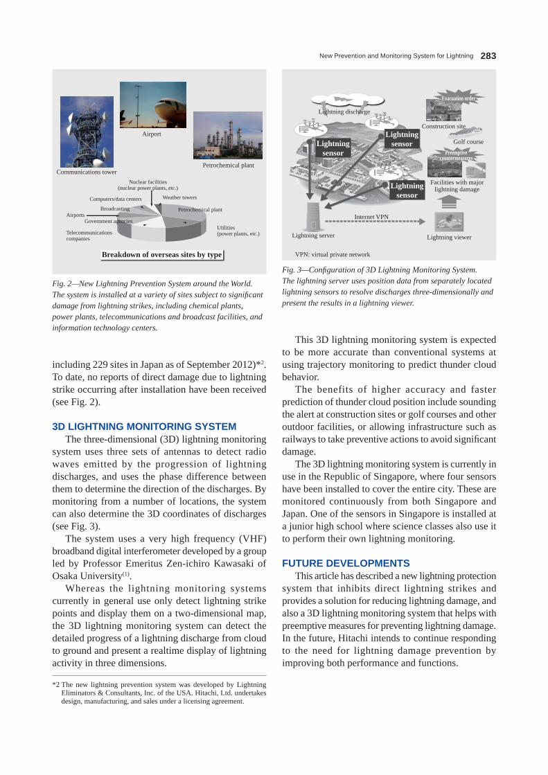
New Prevention and Monitoring System for Lightning 283
including 229 sites in Japan as of September 2012)*2. To date, no reports of direct damage due to lightning strike occurring after installation have been received (see Fig. 2).
3D LIGHTNING MONITORING SYSTEMThe three-dimensional (3D) lightning monitoring
system uses three sets of antennas to detect radio waves emitted by the progression of lightning discharges, and uses the phase difference between them to determine the direction of the discharges. By monitoring from a number of locations, the system can also determine the 3D coordinates of discharges (see Fig. 3).
The system uses a very high frequency (VHF) broadband digital interferometer developed by a group led by Professor Emeritus Zen-ichiro Kawasaki of Osaka University(1).
Whereas the lightning monitoring systems currently in general use only detect lightning strike points and display them on a two-dimensional map, the 3D lightning monitoring system can detect the detailed progress of a lightning discharge from cloud to ground and present a realtime display of lightning activity in three dimensions.
This 3D lightning monitoring system is expected to be more accurate than conventional systems at using trajectory monitoring to predict thunder cloud behavior.
The benefits of higher accuracy and faster prediction of thunder cloud position include sounding the alert at construction sites or golf courses and other outdoor facilities, or allowing infrastructure such as railways to take preventive actions to avoid significant damage.
The 3D lightning monitoring system is currently in use in the Republic of Singapore, where four sensors have been installed to cover the entire city. These are monitored continuously from both Singapore and Japan. One of the sensors in Singapore is installed at a junior high school where science classes also use it to perform their own lightning monitoring.
FUTURE DEVELOPMENTSThis article has described a new lightning protection
system that inhibits direct lightning strikes and provides a solution for reducing lightning damage, and also a 3D lightning monitoring system that helps with preemptive measures for preventing lightning damage. In the future, Hitachi intends to continue responding to the need for lightning damage prevention by improving both performance and functions.
Petrochemical plant
Utilities(power plants, etc.)Telecommunications
companies
Government agenciesAirports
Broadcasting
Computers/data centers
Nuclear facilities(nuclear power plants, etc.)
Weather towers
Petrochemical plant
Airport
Communications tower
Breakdown of overseas sites by type
Fig. 2—New Lightning Prevention System around the World.The system is installed at a variety of sites subject to significant damage from lightning strikes, including chemical plants, power plants, telecommunications and broadcast facilities, and information technology centers.
Evacuation order
Preemptivecountermeasures
Construction site
Golf course
Facilities with majorlightning damage
Lightningsensor
Lightningsensor
Lightningsensor
Lightning discharge
Lightning server
Internet VPN
Lightning viewer
Fig. 3—Configuration of 3D Lightning Monitoring System.The lightning server uses position data from separately located lightning sensors to resolve discharges three-dimensionally and present the results in a lightning viewer.
VPN: virtual private network
*2 The new lightning prevention system was developed by Lightning Eliminators & Consultants, Inc. of the USA. Hitachi, Ltd. undertakes design, manufacturing, and sales under a licensing agreement.
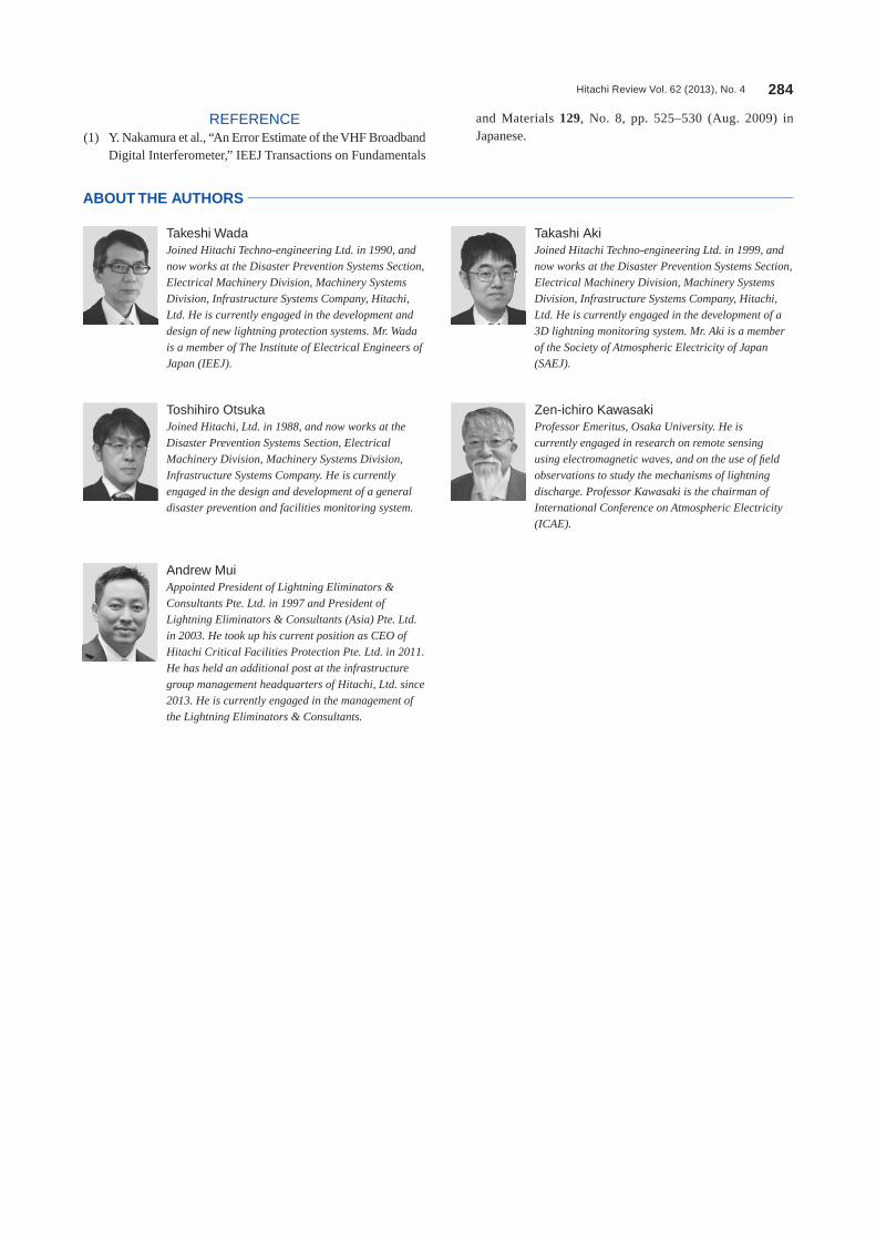
Hitachi Review Vol. 62 (2013), No. 4 284
Takeshi WadaJoined Hitachi Techno-engineering Ltd. in 1990, and now works at the Disaster Prevention Systems Section, Electrical Machinery Division, Machinery Systems Division, Infrastructure Systems Company, Hitachi, Ltd. He is currently engaged in the development and design of new lightning protection systems. Mr. Wada is a member of The Institute of Electrical Engineers of Japan (IEEJ).
Takashi AkiJoined Hitachi Techno-engineering Ltd. in 1999, and now works at the Disaster Prevention Systems Section, Electrical Machinery Division, Machinery Systems Division, Infrastructure Systems Company, Hitachi, Ltd. He is currently engaged in the development of a 3D lightning monitoring system. Mr. Aki is a member of the Society of Atmospheric Electricity of Japan (SAEJ).
Toshihiro OtsukaJoined Hitachi, Ltd. in 1988, and now works at the Disaster Prevention Systems Section, Electrical Machinery Division, Machinery Systems Division, Infrastructure Systems Company. He is currently engaged in the design and development of a general disaster prevention and facilities monitoring system.
Zen-ichiro KawasakiProfessor Emeritus, Osaka University. He is currently engaged in research on remote sensing using electromagnetic waves, and on the use of field observations to study the mechanisms of lightning discharge. Professor Kawasaki is the chairman of International Conference on Atmospheric Electricity (ICAE).
Andrew MuiAppointed President of Lightning Eliminators & Consultants Pte. Ltd. in 1997 and President of Lightning Eliminators & Consultants (Asia) Pte. Ltd. in 2003. He took up his current position as CEO of Hitachi Critical Facilities Protection Pte. Ltd. in 2011. He has held an additional post at the infrastructure group management headquarters of Hitachi, Ltd. since 2013. He is currently engaged in the management of the Lightning Eliminators & Consultants.
ABOUT THE AUTHORS
REFERENCE(1) Y. Nakamura et al., “An Error Estimate of the VHF Broadband
Digital Interferometer,” IEEJ Transactions on Fundamentals
and Materials 129, No. 8, pp. 525–530 (Aug. 2009) in Japanese.
Hitachi Review Vol. 62 (2013), No. 4 285
Autonomous Forklift Automatic Guided Vehicle
topics
Kunihiko Aoki Hideaki Furuno Jun Nagaoka Koji Furukawa
OVERVIEW OF AUTONOMOUS AGVHITACHI has successfully delivered an automatic guided vehicle (AGV) system to South Korean industrial machinery manufacturer, Hanwha Tech M Co., Ltd. The requirements submitted by the client in advance were as follows.(1) AGVs should be able to handle special-purpose trolleys which are placed at two different heights (floor and conveyor) (see Fig. 1).(2) AGVs should be able to travel without following any travel guides that need to be installed on the floor and can potentially damage it.(3) The traveling route of AGVs needs to be capable of easy modification in case of changes to the factory layout.
FEATURES OF AUTONOMOUS AGVConventional AGVs required traveling guides
to indicate the path to follow. These used specific materials such as magnets, markers, or reflectors on the floor or walls along the traveling route. On the other hand, Hitachi’s autonomous AGV is able to identify its own position on an electronic map by using a laser rangefinder and Hitachi’s novel localization algorithm. The system uses these to follow preset routes (see Table 1).
STRUCTURE OF THE SYSTEM(1) Types of AGV
A forklift AGV is used to satisfy ‘requirement (1)’ of the client, described above (see Fig. 2).
OVERVIEW: One of advantages using our autonomous AGV is that it is equipped with a localization algorithm that is able to recognize its own position on an electronic map and trace the preset routes without following any traveling guide on the floor. Hitachi received an order for autonomous forklift AGVs from Hanwha Tech M Co., Ltd. of South Korea in September 2011, and completed delivery in June 2012. The system consists of three main parts: 22 AGVs, a vehicle control system, and approximately 300 stations that are spread across a floor space of 15,000 m2 at the facility. The main purpose of using AGVs is to convey special-purpose trolleys between automated warehouses and manufacturing equipment at the facility, where the total number of transport movements per day is approximately 3,500.
Item Description
Localizationalgorithm (1) First, staff use a laser rangefinder to make
an electronic map. (2) When traveling, the AGV can determine its position on the map using the same laser rangefinder.
Travel guide installation Not required
On-site work Adjustment work only
In-floor installation Not required
Layout changes Adjustment work only
Laser light
Laser rangefinder
TABLE 1. Features of Autonomous AGVHitachi’s autonomous AGV uses a laser rangefinder and localization algorithm to identify its own position.
Automated warehouseConveyor-based materials handling
ConveyorSpecial-purpose trolley
Material
Manufacturing equipmentPlace items on floor
Transport
Fig. 1—Material Handling Methods.Special-purpose trolleys are placed at two different heights (floor and conveyor).
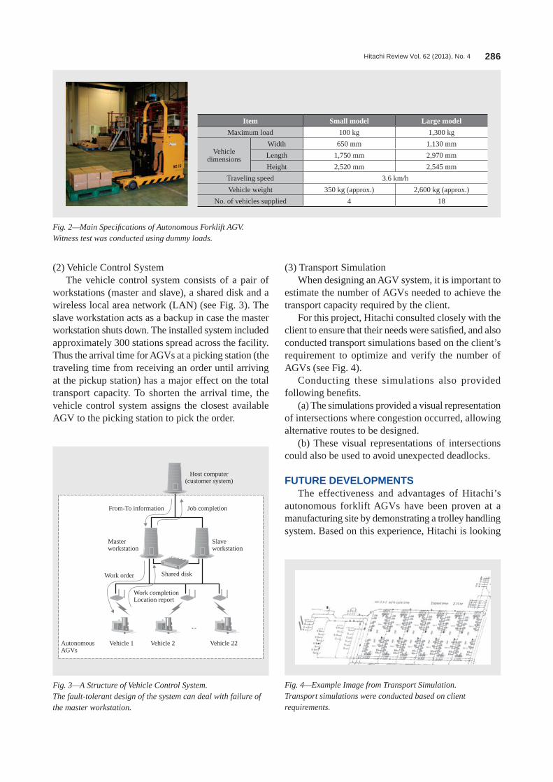
Hitachi Review Vol. 62 (2013), No. 4 286
(2) Vehicle Control SystemThe vehicle control system consists of a pair of
workstations (master and slave), a shared disk and a wireless local area network (LAN) (see Fig. 3). The slave workstation acts as a backup in case the master workstation shuts down. The installed system included approximately 300 stations spread across the facility. Thus the arrival time for AGVs at a picking station (the traveling time from receiving an order until arriving at the pickup station) has a major effect on the total transport capacity. To shorten the arrival time, the vehicle control system assigns the closest available AGV to the picking station to pick the order.
(3) Transport Simulation When designing an AGV system, it is important to
estimate the number of AGVs needed to achieve the transport capacity required by the client.
For this project, Hitachi consulted closely with the client to ensure that their needs were satisfied, and also conducted transport simulations based on the client’s requirement to optimize and verify the number of AGVs (see Fig. 4).
Conducting these simulations also provided following benefits.
(a) The simulations provided a visual representation of intersections where congestion occurred, allowing alternative routes to be designed.
(b) These visual representations of intersections could also be used to avoid unexpected deadlocks.
FUTURE DEVELOPMENTSThe effectiveness and advantages of Hitachi’s
autonomous forklift AGVs have been proven at a manufacturing site by demonstrating a trolley handling system. Based on this experience, Hitachi is looking
Fig. 4—Example Image from Transport Simulation.Transport simulations were conducted based on client requirements.
Fig. 2—Main Specifications of Autonomous Forklift AGV.Witness test was conducted using dummy loads.
Item Small model Large model
Maximum load 100 kg 1,300 kg
Vehicle dimensions
Width 650 mm 1,130 mm
Length 1,750 mm 2,970 mm
Height 2,520 mm 2,545 mm
Traveling speed 3.6 km/h
Vehicle weight 350 kg (approx.) 2,600 kg (approx.)
No. of vehicles supplied 4 18
Host computer(customer system)
Job completionFrom-To information
Masterworkstation
Slaveworkstation
Shared diskWork order
Work completionLocation report
Vehicle 22Vehicle 2
...
Vehicle 1Autonomous AGVs
Fig. 3—A Structure of Vehicle Control System.The fault-tolerant design of the system can deal with failure of the master workstation.

Autonomous Forklift Automatic Guided Vehicle 287
towards further opportunities at other manufacturing sites in the region with the aims of expanding and
improving its business.
Kunihiko AokiJoined Hitachi Kiden Kogyo, Ltd. in 1982, and now works at the Logistics Systems Department, Electrical Machinery Division, Machinery Systems Division, Infrastructure Systems Company, Hitachi, Ltd. He is currently the Leader of the Autonomous AGV section.
Hideaki FurunoJoined Hitachi Techno-engineering Ltd. in 1990, and now works at the Logistics Systems Department, Electrical Machinery Division, Machinery Systems Division, Infrastructure Systems Company, Hitachi, Ltd. He is currently the Leader of the Autonomous AGV Control Design section.
Jun NagaokaJoined Hitachi Kiden Kogyo, Ltd. in 1994, and now works at the Logistics Systems Department, Electrical Machinery Division, Machinery Systems Division, Infrastructure Systems Company, Hitachi, Ltd. He is currently engaged in designing Autonomous AGV systems.
Koji FurukawaJoined Hitachi Kiden Kogyo, Ltd. in 2003, and now works at the Logistics Systems Department, Electrical Machinery Division, Machinery Systems Division, Infrastructure Systems Company, Hitachi, Ltd. He is currently engaged in designing Autonomous AGV systems.
ABOUT THE AUTHORS