specialissuepaper 259
TRANSCRIPT
SPECIAL ISSUE PAPER 259
Optimization of the tribological performance ofrectangular seals in automotive transmissionsM Gronitzki and G W G Poll∗
Institute of Machine Elements, Engineering Design and Tribology, Hannover University, Hannover, Germany
The manuscript was received on 18 September 2006 and was accepted after revision for publication on 8 February 2007.
DOI: 10.1243/13506501JET247
Abstract: Rectangular seals – a special type of face seals – are currently used in rotatingconnections of automatic automotive transmissions (double clutch transmissions, continuouslyvariable transmissions, and 6-automated transmission) for the oil pressure supply of rotatingcontrol and actuator elements. Friction losses of several kilowatts can occur in the sealing sys-tem, causing a considerable reduction in efficiency. As a result of ongoing progress in powertrain design, sliding speeds and fluid pressures continue to increase. Therefore, due to frictionrelated temperature rise in the sealing contact, extensive oil carbonization may occur. For boththe reasons, developing friction optimized seals is crucial.
For cost and design reasons grey cast iron rings are more and more substituted by modern,high temperature resistant thermoplastics. These materials also exhibit better friction and wearperformance which can further be improved by adding polytetrafluorethylen or graphite.
Because of their lower stiffness compared with metallic components, special thoughts haveto be given to the design of thermoplastic rectangular seals. This paper describes how animproved geometry with optimized friction and wear performance was achieved by combiningexperimental investigations and numerical calculations on thermomechanical deflections.
Keywords: rectangular seals, automotive transmission, high temperature plastics
1 INTRODUCTION
At the beginning of the nineties only manual orautomated stepped transmissions with planetarygears and hydrodynamic torque converter were avail-able for passenger cars. Today, a variety of trans-mission types are in series production. Among thoseare automated manual transmissions, double clutchtransmissions (DCT), continuously variable transmis-sions (CVT) in different designs and modern auto-mated transmissions with up to seven gear ratios. It isexpected that the market share of these transmissiontypes will increase.
Most of these transmissions contain rotating actu-ators which are activated by means of pressurizedoil. In most cases one or several sealed connections
∗Corresponding author: Institute of Machine Elements, Engineer-
ing Design and Tribology, Hannover University, Welfengarten 1A,
Hannover D-30167, Germany. email: [email protected]
exist for the oil transfer from the stationary parts intothe rotating shaft. These rotating connections have tosustain pressures up to 2.5 MPa in automated trans-mission (AT) and up to 8 MPa in CVT-applications.At shaft speeds up to 7500 r/min and shaft diametersof up to 80 mm power losses of more than 1 kW canoccur. These reduce the efficiency of the transmissionand lead to a high thermal stress of the seal and thesealed fluid.
Rectangular seal rings are commonly used in thoserotating connections; they are located between theshoulder of a groove in the rotating shaft and the sur-rounding housing and direct the oil radially into thetransmission shaft. The seal design is quite similar topiston rings but instead of a reciprocating motion theseal rotates. The sliding movement can take place atthe side face or at the circumference of the seal. Usu-ally no positive interlocking or strong enough pressfit exists between the seal and the surrounding partswhich would prevent a relative rotation.
Originally grey cast iron alloys were used as seal-ing ring material. Polytetrafluorethylen (PTFE) and
JET247 © IMechE 2007 Proc. IMechE Vol. 221 Part J: J. Engineering Tribology
260 M Gronitzki and G W G Poll
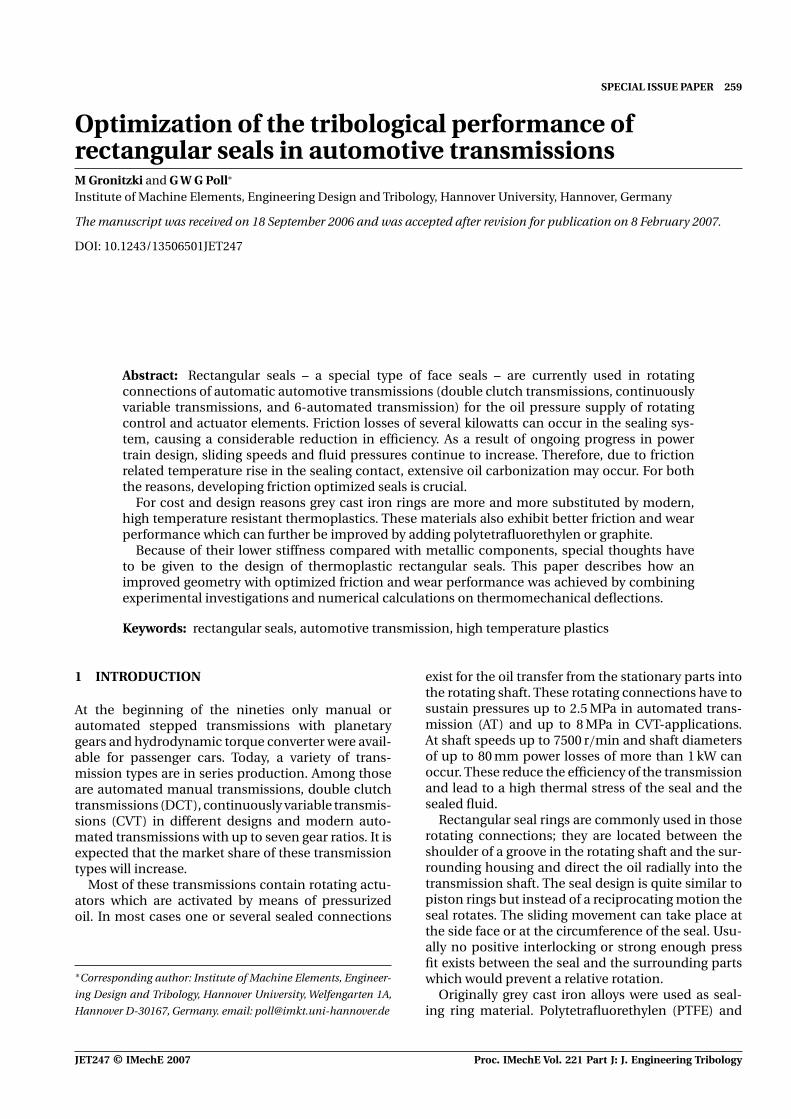
Fig. 1 Design of the sealing system
ethylene-tetrafluorethylene (ETFE) were introducedfor the first time at the beginning of the nineties; theywere replaced later on by high temperature resistentplastics (ht-plastics) such as polyetheretherketon(PEEK), polyamidimid (PAI), polyimid, and thermo-plastic polyimide (TPI). Some of these materials areable to operate permanently at temperatures up to300 ◦C [1–3] (Fig. 1).
In order to mount the seals in the groove on theshaft it is necessary to expand them to the shaft outerdiameter. For this purpose they are provided with ajoint which also compensates tolerances of diameter,wear and thermal changes of length during operation.This joint causes a considerably higher leakage thanthe remaining parts of the sealing system, but, as theoil remains in the transmission and does not leak intothe environment, such a leakage is tolerable withinlimits. In order to minimize leakage through the joint,a number of different designs with narrow gaps andmultiple baffles were developed [1].
Compared to most mechanical face seals this seemsto be a fairly simple system; however, to ensure properand reliable functioning as well as high efficiency
detailed knowledge of the mechanisms involved isrequired. However, so far, rectangular shaft seals haverarely been the subject of in-depth research, a factwhich inspired the investigations, part of which ispresented in this paper.
2 EXPERIMENTAL SETUP
2.1 Test equipment
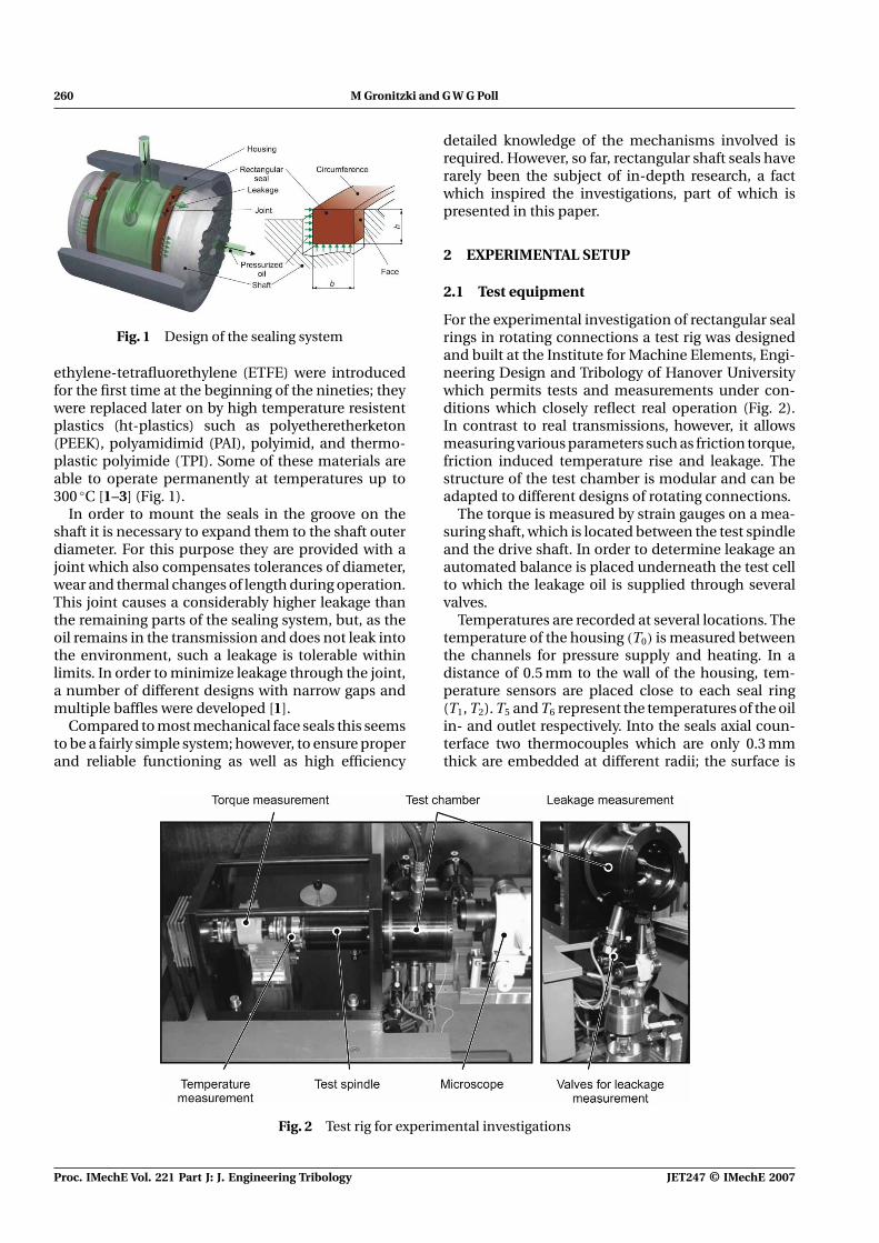
For the experimental investigation of rectangular sealrings in rotating connections a test rig was designedand built at the Institute for Machine Elements, Engi-neering Design and Tribology of Hanover Universitywhich permits tests and measurements under con-ditions which closely reflect real operation (Fig. 2).In contrast to real transmissions, however, it allowsmeasuring various parameters such as friction torque,friction induced temperature rise and leakage. Thestructure of the test chamber is modular and can beadapted to different designs of rotating connections.
The torque is measured by strain gauges on a mea-suring shaft, which is located between the test spindleand the drive shaft. In order to determine leakage anautomated balance is placed underneath the test cellto which the leakage oil is supplied through severalvalves.
Temperatures are recorded at several locations. Thetemperature of the housing (T0) is measured betweenthe channels for pressure supply and heating. In adistance of 0.5 mm to the wall of the housing, tem-perature sensors are placed close to each seal ring(T1, T2). T5 and T6 represent the temperatures of the oilin- and outlet respectively. Into the seals axial coun-terface two thermocouples which are only 0.3 mmthick are embedded at different radii; the surface is
Fig. 2 Test rig for experimental investigations
Proc. IMechE Vol. 221 Part J: J. Engineering Tribology JET247 © IMechE 2007
Optimization of the tribological performance of rectangular seals 261
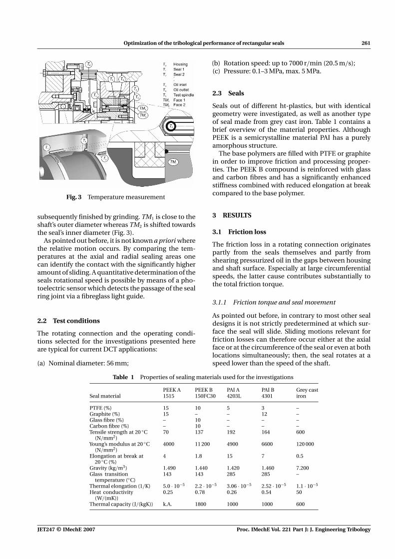
Fig. 3 Temperature measurement
subsequently finished by grinding. TM1 is close to theshaft’s outer diameter whereas TM2 is shifted towardsthe seal’s inner diameter (Fig. 3).
As pointed out before, it is not known a priori wherethe relative motion occurs. By comparing the tem-peratures at the axial and radial sealing areas onecan identify the contact with the significantly higheramount of sliding. A quantitative determination of theseals rotational speed is possible by means of a pho-toelectric sensor which detects the passage of the sealring joint via a fibreglass light guide.
2.2 Test conditions
The rotating connection and the operating condi-tions selected for the investigations presented hereare typical for current DCT applications:
(a) Nominal diameter: 56 mm;
(b) Rotation speed: up to 7000 r/min (20.5 m/s);(c) Pressure: 0.1–3 MPa, max. 5 MPa.
2.3 Seals
Seals out of different ht-plastics, but with identicalgeometry were investigated, as well as another typeof seal made from grey cast iron. Table 1 contains abrief overview of the material properties. AlthoughPEEK is a semicrystalline material PAI has a purelyamorphous structure.
The base polymers are filled with PTFE or graphitein order to improve friction and processing proper-ties. The PEEK B compound is reinforced with glassand carbon fibres and has a significantly enhancedstiffness combined with reduced elongation at breakcompared to the base polymer.
3 RESULTS
3.1 Friction loss
The friction loss in a rotating connection originatespartly from the seals themselves and partly fromshearing pressurized oil in the gaps between housingand shaft surface. Especially at large circumferentialspeeds, the latter cause contributes substantially tothe total friction torque.
3.1.1 Friction torque and seal movement
As pointed out before, in contrary to most other sealdesigns it is not strictly predetermined at which sur-face the seal will slide. Sliding motions relevant forfriction losses can therefore occur either at the axialface or at the circumference of the seal or even at bothlocations simultaneously; then, the seal rotates at aspeed lower than the speed of the shaft.
Table 1 Properties of sealing materials used for the investigations
PEEK A PEEK B PAI A PAI B Grey castSeal material 1515 150FC30 4203L 4301 iron
PTFE (%) 15 10 5 3 –Graphite (%) 15 – – 12 –Glass fibre (%) – 10 – – –Carbon fibre (%) – 10 – – –Tensile strength at 20 ◦C
(N/mm2)70 137 192 164 600
Young’s modulus at 20 ◦C(N/mm2)
4000 11 200 4900 6600 120 000
Elongation at break at20 ◦C (%)
4 1.8 15 7 0.5
Gravity (kg/m3) 1.490 1.440 1.420 1.460 7.200Glass transition
temperature (◦C)143 143 285 285 –
Thermal elongation (1/K) 5.0 · 10−5 2.2 · 10−5 3.06 · 10−5 2.52 · 10−5 1.1 · 10−5
Heat conductivity(W/(mK))
0.25 0.78 0.26 0.54 50
Thermal capacity (J/(kgK)) k.A. 1800 1000 1000 600
JET247 © IMechE 2007 Proc. IMechE Vol. 221 Part J: J. Engineering Tribology
262 M Gronitzki and G W G Poll
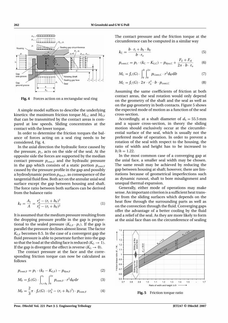
Fig. 4 Forces action on a rectangular seal ring
A simple model suffices to describe the underlyingkinetics: the maximum friction torque MF,C and MF,F
that can be transmitted by the contact areas is com-pared at low speeds. Sliding concentrates at thecontact with the lower torque.
In order to determine the friction torques the bal-ance of forces acting on a seal ring needs to beconsidered, Fig. 4.
In the axial direction the hydraulic force caused bythe pressure, p1, acts on the side of the seal. At theopposite side the forces are supported by the mediancontact pressure pcont,F and the hydraulic pressurein the gap which consists of a static portion pcont,F
caused by the pressure profile in the gap and possiblya hydrodynamic portion pdyn,F, as consequence of thetangential fluid flow. Both act on the annular axial sealsurface except the gap between housing and shaft.The force ratio between both surfaces can be derivedfrom the balance ratio
kF = A1
A= r2
o − (ri + hF)2
r2S − (ri + hF)2
(1)
It is assumed that the medium pressure resulting fromthe dropping pressure profile in the gap is propor-tional to the sealed pressure (KG,F · p1). If the gap isparallel the pressure declines almost linear. The factorKG,F becomes 0.5. In the case of a convergent gap thefluid pressure is able to penetrate further into the gapso that the load at the sliding face is reduced (KG → 1).If the gap is divergent the effect is reverse (KG → 0).
The contact pressure at the face and the corre-sponding friction torque can now be calculated asfollows
pcont,F = p1 · (kF − KG,F) − pdyn,F (2)
MF = fF(G) ·∫ rS
ri+hf
∫ 2π
0pcont,F · r2dϕdr (3)
MF = 23π · fF(G) · (r3
S − (ri + hF)3) · pcont,F (4)
The contact pressure and the friction torque at thecircumference can be computed in a similar way
kC = b · ri + bF · hF
b · ro(5)
pcont,C = p1 · (kC − KG,C) − pdyn,C + FZ + Fel
2π · b · ro(6)
MC = fC(G) ·∫ b
0
∫ 2π
0pCont,C · r2dϕdb (7)
MC = fC(G) · 2π · r2o · b · pcont,C (8)
Assuming the same coefficients of friction at bothcontact areas, the seal rotation would only dependon the geometry of the shaft and the seal as well ason the gap geometry in both contacts. Figure 5 showsthe expected mode of motion as a function of the sealcross-section.
Accordingly, at a shaft diameter of dS = 55.5 mmand a square cross-section, in theory the slidingmotion should exclusively occur at the circumfer-ential surface of the seal, which is usually not thepreferred mode of operation. In order to prevent arotation of the seal with respect to the housing, theratio of width and height has to be increased tob/h = 1.22.
In the most common case of a converging gap atthe axial face, a smaller seal width may be chosen.The same result may be achieved by reducing thegap between housing at shaft; however, there are lim-itations because of geometrical imperfections suchas dynamic runout, shaft to bore misalignment andunequal thermal expansion.
Generally, either mode of operations may makesense. An important criterion is a sufficient heat trans-fer from the sliding surfaces which depends on theheat flow through the surrounding parts as well ason the convection through the fluid. Converging gapsoffer the advantage of a better cooling by the fluidand a relief of the seal. As they are more likely to format the axial face than on the circumference of sealing
Fig. 5 Friction torque ratio
Proc. IMechE Vol. 221 Part J: J. Engineering Tribology JET247 © IMechE 2007

Optimization of the tribological performance of rectangular seals 263
rings there is a preference for an axial sliding contactin most applications.
3.1.2 Creep rotation
The experimental investigations focused on sealswhich are intended to rotate relatively to the shaft.In reality, however, those seals were found to rotaterelatively to the housing as well, albeit at low speed.This was already observed earlier by other authors,e.g. Rogler [4], but attributed to small radial move-ments of shaft. Instead, it became obvious that oscil-lating axial movements between shaft and sealingring help to overcome static friction and thus adda circumferential component to sliding velocity. The
axial motions are imposed by axial runout of both thesealing ring face and the shoulder of the groove inthe shaft. Such geometrical imperfections are alwayspresent to some extent (Fig. 6).
3.1.3 Calculations on temperature distribution andseal deformations
The operating limit of rotary shaft seals is often givenby the temperature in the sealing zone. Either the fluidwhich has to be sealed may evaporate or be pyrolizedor the solid materials may loose properties requiredfor proper functioning. The temperature in the sealinggap is determined by the frictional heat generated in
Fig. 6 Creep rotation, theoretical model, and measurement
JET247 © IMechE 2007 Proc. IMechE Vol. 221 Part J: J. Engineering Tribology
264 M Gronitzki and G W G Poll
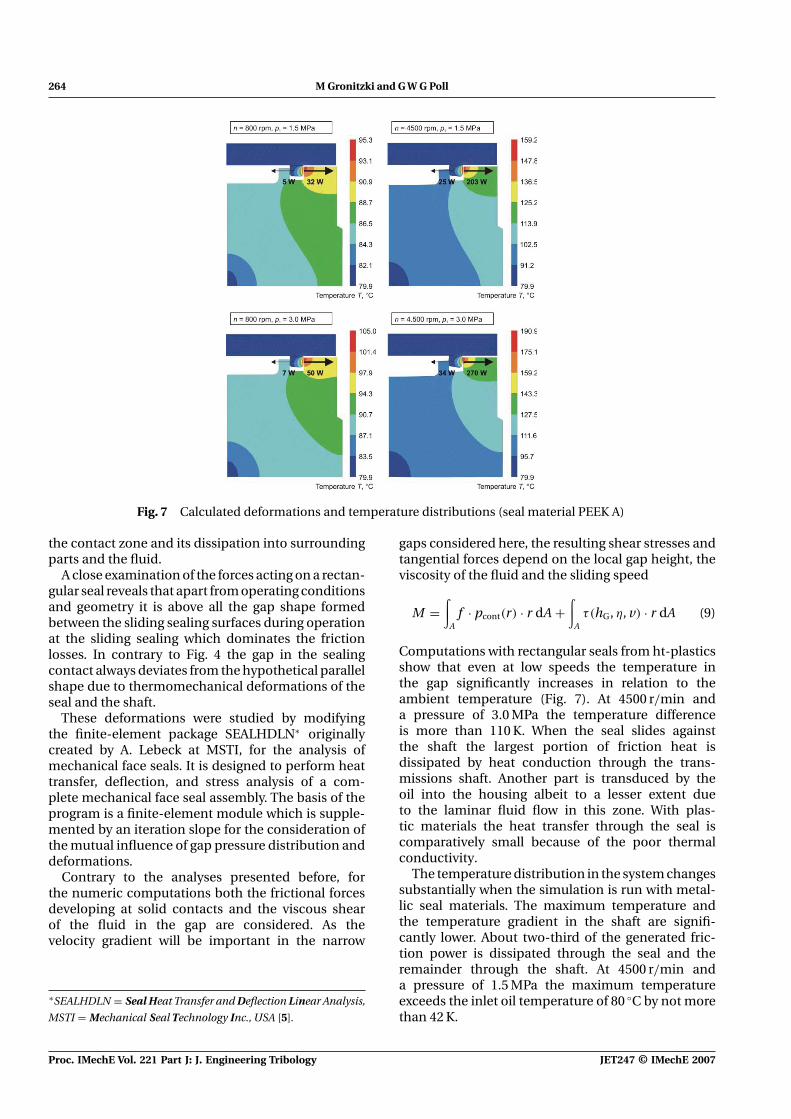
Fig. 7 Calculated deformations and temperature distributions (seal material PEEK A)
the contact zone and its dissipation into surroundingparts and the fluid.
A close examination of the forces acting on a rectan-gular seal reveals that apart from operating conditionsand geometry it is above all the gap shape formedbetween the sliding sealing surfaces during operationat the sliding sealing which dominates the frictionlosses. In contrary to Fig. 4 the gap in the sealingcontact always deviates from the hypothetical parallelshape due to thermomechanical deformations of theseal and the shaft.
These deformations were studied by modifyingthe finite-element package SEALHDLN∗ originallycreated by A. Lebeck at MSTI, for the analysis ofmechanical face seals. It is designed to perform heattransfer, deflection, and stress analysis of a com-plete mechanical face seal assembly. The basis of theprogram is a finite-element module which is supple-mented by an iteration slope for the consideration ofthe mutual influence of gap pressure distribution anddeformations.
Contrary to the analyses presented before, forthe numeric computations both the frictional forcesdeveloping at solid contacts and the viscous shearof the fluid in the gap are considered. As thevelocity gradient will be important in the narrow
∗SEALHDLN = Seal Heat Transfer and Deflection Linear Analysis,
MSTI = Mechanical Seal Technology Inc., USA [5].
gaps considered here, the resulting shear stresses andtangential forces depend on the local gap height, theviscosity of the fluid and the sliding speed
M =∫
Af · pcont(r) · r dA +
∫Aτ(hG, η, v) · r dA (9)
Computations with rectangular seals from ht-plasticsshow that even at low speeds the temperature inthe gap significantly increases in relation to theambient temperature (Fig. 7). At 4500 r/min anda pressure of 3.0 MPa the temperature differenceis more than 110 K. When the seal slides againstthe shaft the largest portion of friction heat isdissipated by heat conduction through the trans-missions shaft. Another part is transduced by theoil into the housing albeit to a lesser extent dueto the laminar fluid flow in this zone. With plas-tic materials the heat transfer through the seal iscomparatively small because of the poor thermalconductivity.
The temperature distribution in the system changessubstantially when the simulation is run with metal-lic seal materials. The maximum temperature andthe temperature gradient in the shaft are signifi-cantly lower. About two-third of the generated fric-tion power is dissipated through the seal and theremainder through the shaft. At 4500 r/min anda pressure of 1.5 MPa the maximum temperatureexceeds the inlet oil temperature of 80 ◦C by not morethan 42 K.
Proc. IMechE Vol. 221 Part J: J. Engineering Tribology JET247 © IMechE 2007
Optimization of the tribological performance of rectangular seals 265
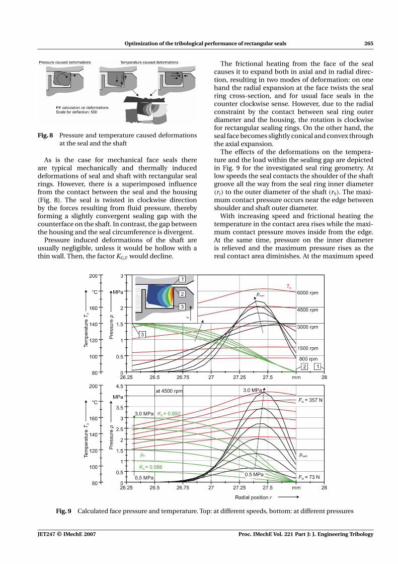
Fig. 8 Pressure and temperature caused deformationsat the seal and the shaft
As is the case for mechanical face seals thereare typical mechanically and thermally induceddeformations of seal and shaft with rectangular sealrings. However, there is a superimposed influencefrom the contact between the seal and the housing(Fig. 8). The seal is twisted in clockwise directionby the forces resulting from fluid pressure, therebyforming a slightly convergent sealing gap with thecounterface on the shaft. In contrast, the gap betweenthe housing and the seal circumference is divergent.
Pressure induced deformations of the shaft areusually negligible, unless it would be hollow with athin wall. Then, the factor KG,F would decline.
The frictional heating from the face of the sealcauses it to expand both in axial and in radial direc-tion, resulting in two modes of deformation: on onehand the radial expansion at the face twists the sealring cross-section, and for usual face seals in thecounter clockwise sense. However, due to the radialconstraint by the contact between seal ring outerdiameter and the housing, the rotation is clockwisefor rectangular sealing rings. On the other hand, theseal face becomes slightly conical and convex throughthe axial expansion.
The effects of the deformations on the tempera-ture and the load within the sealing gap are depictedin Fig. 9 for the investigated seal ring geometry. Atlow speeds the seal contacts the shoulder of the shaftgroove all the way from the seal ring inner diameter(ri) to the outer diameter of the shaft (rS). The maxi-mum contact pressure occurs near the edge betweenshoulder and shaft outer diameter.
With increasing speed and frictional heating thetemperature in the contact area rises while the maxi-mum contact pressure moves inside from the edge.At the same time, pressure on the inner diameteris relieved and the maximum pressure rises as thereal contact area diminishes. At the maximum speed
Fig. 9 Calculated face pressure and temperature. Top: at different speeds, bottom: at different pressures
JET247 © IMechE 2007 Proc. IMechE Vol. 221 Part J: J. Engineering Tribology
266 M Gronitzki and G W G Poll
of 6000 r/min the real contact is only 1 mm widealthough the nominal length of the contact is nearlytwice. However, the slope of the contact pressure dis-tribution declines due to the hydrostatic load reliefprovided from the pressurized oil that penetrates intothe convergent gap from the inner diameter (KG =0.663); this means, that the total resulting radial forcecarried by the sealing contact decreases at higherspeeds.
If the sealed pressure increases at constant speedthe pressure peak shifts towards the outer diame-ter. The pressure related deformation has a moresignificant relieving effect than temperature; asa result, the total normal force and the frictiontorque increase less than proportional to the sealedpressure.
As mentioned before, a totally different behaviouris expected for seals from grey cast iron. The centre ofthe contact pressure distribution also shifts outwardwhen the friction induced temperature increases, but,due to the higher stiffness of the material, deforma-tions do not suffice to form a gap geometry withsignificant load relief.
In summary, the simulations reveal a stronginteraction between mechanical and thermal defor-mations, sealing gap geometry, fluid pressure profile,contact forces, friction, and heat generation. Thishas a positive effect on the operation of seals madefrom ht-plastics as high fluid pressures are partiallycompensated by hydrostatic forces due to the result-ing converging gap geometry, provided sliding isrestricted to the axial face. In comparison, the con-tact forces and friction losses of grey cast iron sealsare expected to grow more pronouncedly with sealedfluid pressures.
The high sliding surface temperatures of seals fromht-plastics have both advantages and disadvantages.It is unfavourable that both the liquid which is tobe sealed and the sealing ring are exposed to highthermal stresses. It is an advantage, though, thatfluid viscosity within the gap and thus viscous sheardecline.
3.2 Leakage
In sealing systems with rectangular seals, there areseveral parallel leakage paths. Apart from the axialsealing contact there is the radial contact at thecircumference as well as the joint.
Knowing the detailed geometry, the pressure pro-file, the temperatures and the viscosity and the geom-etry of the joint, an estimate of the respective leakageshares can be obtained with simple analytical com-putations based on the Reynolds equation for thecontacting faces and Bernoulli equations for the joint.Obviously, the leakage through the joint dominates
by far. The amount of leakage passing the seal at thecircumference and the face is almost negligible.
Because of the abrupt changes in the channel widthand flow direction, more accurate results for the flowthrough the joint can be achieved with the numericalmethods of computational fluid dynamics, however,at the expense of considerable computation times.
3.3 Measurements
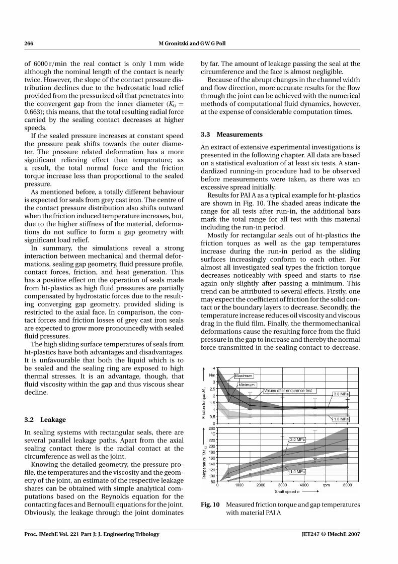
An extract of extensive experimental investigations ispresented in the following chapter. All data are basedon a statistical evaluation of at least six tests. A stan-dardized running-in procedure had to be observedbefore measurements were taken, as there was anexcessive spread initially.
Results for PAI A as a typical example for ht-plasticsare shown in Fig. 10. The shaded areas indicate therange for all tests after run-in, the additional barsmark the total range for all test with this materialincluding the run-in period.
Mostly for rectangular seals out of ht-plastics thefriction torques as well as the gap temperaturesincrease during the run-in period as the slidingsurfaces increasingly conform to each other. Foralmost all investigated seal types the friction torquedecreases noticeably with speed and starts to riseagain only slightly after passing a minimum. Thistrend can be attributed to several effects. Firstly, onemay expect the coefficient of friction for the solid con-tact or the boundary layers to decrease. Secondly, thetemperature increase reduces oil viscosity and viscousdrag in the fluid film. Finally, the thermomechanicaldeformations cause the resulting force from the fluidpressure in the gap to increase and thereby the normalforce transmitted in the sealing contact to decrease.
Fig. 10 Measured friction torque and gap temperatureswith material PAI A
Proc. IMechE Vol. 221 Part J: J. Engineering Tribology JET247 © IMechE 2007
Optimization of the tribological performance of rectangular seals 267
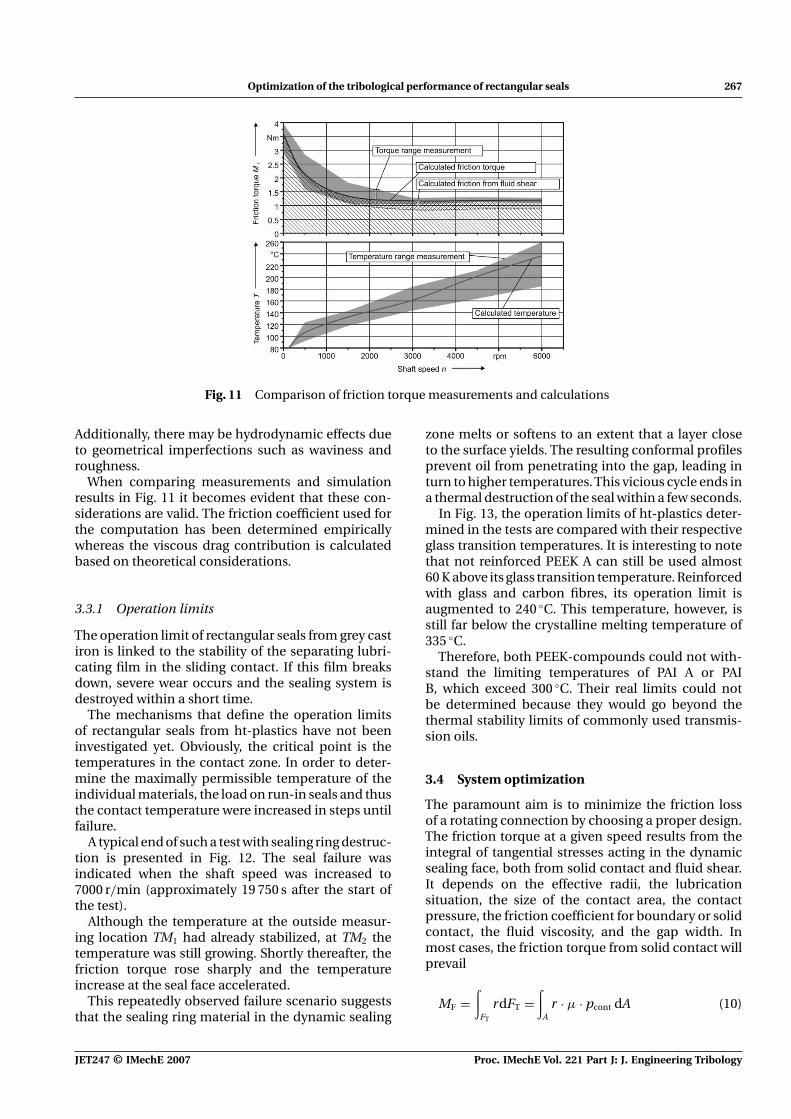
Fig. 11 Comparison of friction torque measurements and calculations
Additionally, there may be hydrodynamic effects dueto geometrical imperfections such as waviness androughness.
When comparing measurements and simulationresults in Fig. 11 it becomes evident that these con-siderations are valid. The friction coefficient used forthe computation has been determined empiricallywhereas the viscous drag contribution is calculatedbased on theoretical considerations.
3.3.1 Operation limits
The operation limit of rectangular seals from grey castiron is linked to the stability of the separating lubri-cating film in the sliding contact. If this film breaksdown, severe wear occurs and the sealing system isdestroyed within a short time.
The mechanisms that define the operation limitsof rectangular seals from ht-plastics have not beeninvestigated yet. Obviously, the critical point is thetemperatures in the contact zone. In order to deter-mine the maximally permissible temperature of theindividual materials, the load on run-in seals and thusthe contact temperature were increased in steps untilfailure.
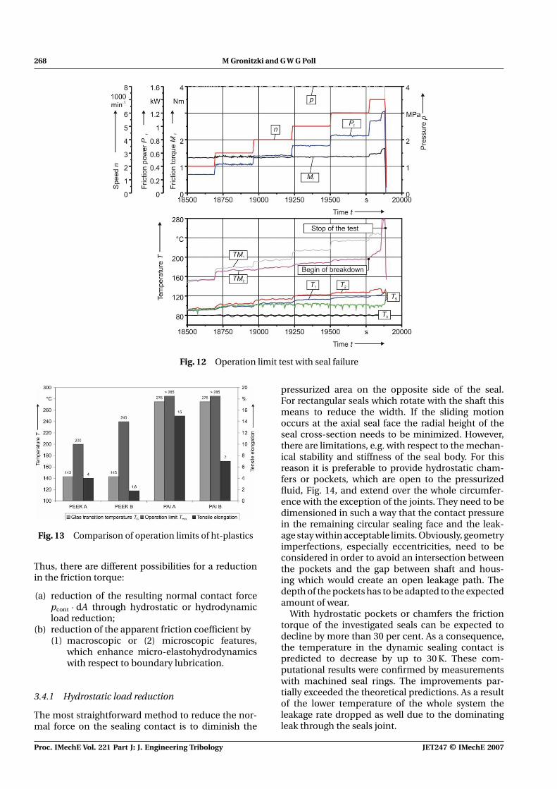
A typical end of such a test with sealing ring destruc-tion is presented in Fig. 12. The seal failure wasindicated when the shaft speed was increased to7000 r/min (approximately 19 750 s after the start ofthe test).
Although the temperature at the outside measur-ing location TM1 had already stabilized, at TM2 thetemperature was still growing. Shortly thereafter, thefriction torque rose sharply and the temperatureincrease at the seal face accelerated.
This repeatedly observed failure scenario suggeststhat the sealing ring material in the dynamic sealing
zone melts or softens to an extent that a layer closeto the surface yields. The resulting conformal profilesprevent oil from penetrating into the gap, leading inturn to higher temperatures. This vicious cycle ends ina thermal destruction of the seal within a few seconds.
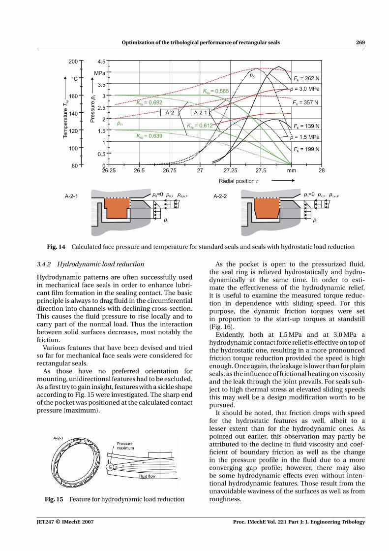
In Fig. 13, the operation limits of ht-plastics deter-mined in the tests are compared with their respectiveglass transition temperatures. It is interesting to notethat not reinforced PEEK A can still be used almost60 K above its glass transition temperature. Reinforcedwith glass and carbon fibres, its operation limit isaugmented to 240 ◦C. This temperature, however, isstill far below the crystalline melting temperature of335 ◦C.
Therefore, both PEEK-compounds could not with-stand the limiting temperatures of PAI A or PAIB, which exceed 300 ◦C. Their real limits could notbe determined because they would go beyond thethermal stability limits of commonly used transmis-sion oils.
3.4 System optimization
The paramount aim is to minimize the friction lossof a rotating connection by choosing a proper design.The friction torque at a given speed results from theintegral of tangential stresses acting in the dynamicsealing face, both from solid contact and fluid shear.It depends on the effective radii, the lubricationsituation, the size of the contact area, the contactpressure, the friction coefficient for boundary or solidcontact, the fluid viscosity, and the gap width. Inmost cases, the friction torque from solid contact willprevail
MF =∫
FT
rdFT =∫
Ar · μ · pcont dA (10)
JET247 © IMechE 2007 Proc. IMechE Vol. 221 Part J: J. Engineering Tribology
268 M Gronitzki and G W G Poll
Fig. 12 Operation limit test with seal failure
Fig. 13 Comparison of operation limits of ht-plastics
Thus, there are different possibilities for a reductionin the friction torque:
(a) reduction of the resulting normal contact forcepcont · dA through hydrostatic or hydrodynamicload reduction;
(b) reduction of the apparent friction coefficient by(1) macroscopic or (2) microscopic features,
which enhance micro-elastohydrodynamicswith respect to boundary lubrication.
3.4.1 Hydrostatic load reduction
The most straightforward method to reduce the nor-mal force on the sealing contact is to diminish the
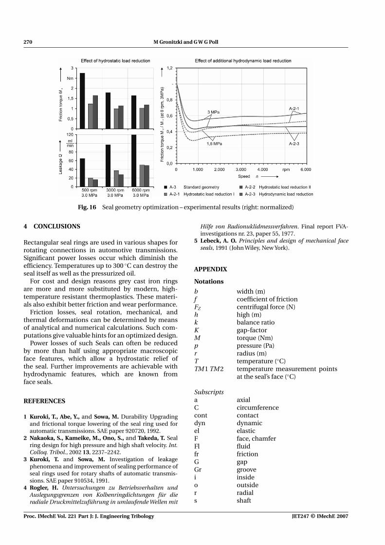
pressurized area on the opposite side of the seal.For rectangular seals which rotate with the shaft thismeans to reduce the width. If the sliding motionoccurs at the axial seal face the radial height of theseal cross-section needs to be minimized. However,there are limitations, e.g. with respect to the mechan-ical stability and stiffness of the seal body. For thisreason it is preferable to provide hydrostatic cham-fers or pockets, which are open to the pressurizedfluid, Fig. 14, and extend over the whole circumfer-ence with the exception of the joints. They need to bedimensioned in such a way that the contact pressurein the remaining circular sealing face and the leak-age stay within acceptable limits. Obviously, geometryimperfections, especially eccentricities, need to beconsidered in order to avoid an intersection betweenthe pockets and the gap between shaft and hous-ing which would create an open leakage path. Thedepth of the pockets has to be adapted to the expectedamount of wear.
With hydrostatic pockets or chamfers the frictiontorque of the investigated seals can be expected todecline by more than 30 per cent. As a consequence,the temperature in the dynamic sealing contact ispredicted to decrease by up to 30 K. These com-putational results were confirmed by measurementswith machined seal rings. The improvements par-tially exceeded the theoretical predictions. As a resultof the lower temperature of the whole system theleakage rate dropped as well due to the dominatingleak through the seals joint.
Proc. IMechE Vol. 221 Part J: J. Engineering Tribology JET247 © IMechE 2007
Optimization of the tribological performance of rectangular seals 269
Fig. 14 Calculated face pressure and temperature for standard seals and seals with hydrostatic load reduction
3.4.2 Hydrodynamic load reduction
Hydrodynamic patterns are often successfully usedin mechanical face seals in order to enhance lubri-cant film formation in the sealing contact. The basicprinciple is always to drag fluid in the circumferentialdirection into channels with declining cross-section.This causes the fluid pressure to rise locally and tocarry part of the normal load. Thus the interactionbetween solid surfaces decreases, most notably thefriction.
Various features that have been devised and triedso far for mechanical face seals were considered forrectangular seals.
As those have no preferred orientation formounting, unidirectional features had to be excluded.As a first try to gain insight, features with a sickle shapeaccording to Fig. 15 were investigated. The sharp endof the pocket was positioned at the calculated contactpressure (maximum).
Fig. 15 Feature for hydrodynamic load reduction
As the pocket is open to the pressurized fluid,the seal ring is relieved hydrostatically and hydro-dynamically at the same time. In order to esti-mate the effectiveness of the hydrodynamic relief,it is useful to examine the measured torque reduc-tion in dependence with sliding speed. For thispurpose, the dynamic friction torques were setin proportion to the start-up torques at standstill(Fig. 16).
Evidently, both at 1.5 MPa and at 3.0 MPa ahydrodynamic contact force relief is effective on top ofthe hydrostatic one, resulting in a more pronouncedfriction torque reduction provided the speed is highenough. Once again, the leakage is lower than for plainseals, as the influence of frictional heating on viscosityand the leak through the joint prevails. For seals sub-ject to high thermal stress at elevated sliding speedsthis may well be a design modification worth to bepursued.
It should be noted, that friction drops with speedfor the hydrostatic features as well, albeit to alesser extent than for the hydrodynamic ones. Aspointed out earlier, this observation may partly beattributed to the decline in fluid viscosity and coef-ficient of boundary friction as well as the changein the pressure profile in the fluid due to a moreconverging gap profile; however, there may alsobe some hydrodynamic effects even without inten-tional hydrodynamic features. Those result from theunavoidable waviness of the surfaces as well as fromroughness.
JET247 © IMechE 2007 Proc. IMechE Vol. 221 Part J: J. Engineering Tribology
270 M Gronitzki and G W G Poll
Fig. 16 Seal geometry optimization – experimental results (right: normalized)
4 CONCLUSIONS
Rectangular seal rings are used in various shapes forrotating connections in automotive transmissions.Significant power losses occur which diminish theefficiency. Temperatures up to 300 ◦C can destroy theseal itself as well as the pressurized oil.
For cost and design reasons grey cast iron ringsare more and more substituted by modern, high-temperature resistant thermoplastics. These materi-als also exhibit better friction and wear performance.
Friction losses, seal rotation, mechanical, andthermal deformations can be determined by meansof analytical and numerical calculations. Such com-putations give valuable hints for an optimized design.
Power losses of such Seals can often be reducedby more than half using appropriate macroscopicface features, which allow a hydrostatic relief ofthe seal. Further improvements are achievable withhydrodynamic features, which are known fromface seals.
REFERENCES
1 Kuroki, T., Abe, Y., and Sowa, M. Durability Upgradingand frictional torque lowering of the seal ring used forautomatic transmissions. SAE paper 920720, 1992.
2 Nakaoka, S., Kameike, M., Ono, S., and Takeda, T. Sealring design for high pressure and high shaft velocity. Int.Colloq. Tribol., 2002 13, 2237–2242.
3 Kuroki, T. and Sowa, M. Investigation of leakagephenomena and improvement of sealing performance ofseal rings used for rotary shafts of automatic transmis-sions. SAE paper 910534, 1991.
4 Rogler, H. Untersuchungen zu Betriebsverhalten undAuslegungsgrenzen von Kolbenringdichtungen für dieradiale Druckmittelzuführung in umlaufende Wellen mit
Hilfe von Radionuklidmessverfahren. Final report FVA-investigations nr. 23, paper 55, 1977.
5 Lebeck, A. O. Principles and design of mechanical faceseals, 1991 (John Wiley, New York).
APPENDIX
Notations
b width (m)f coefficient of frictionFZ centrifugal force (N)h high (m)k balance ratioK gap-factorM torque (Nm)p pressure (Pa)r radius (m)T temperature (◦C)TM 1 TM 2 temperature measurement points
at the seal’s face (◦C)
Subscriptsa axialC circumferencecont contactdyn dynamicel elasticF face, chamferFl fluidfr frictionG gapGr groovei insideo outsider radials shaft
Proc. IMechE Vol. 221 Part J: J. Engineering Tribology JET247 © IMechE 2007