static dynamic characteristics of … library kafb, nm static and dynamic characteristics of centaur...
TRANSCRIPT
N A S A T E C H N I C A L
M E M O R A N D U M
STATIC AND DYNAMIC CHARACTERISTICS OF CENTAUR GIMBAL SYSTEM UNDER THRUST LOAD
https://ntrs.nasa.gov/search.jsp?R=19660007282 2018-05-18T08:27:28+00:00Z
TECH LIBRARY KAFB, NM
STATIC AND DYNAMIC CHARACTERISTICS OF CENTAUR
GIMBAL SYSTEM UNDER THRUST LOAD
By Robert J. Antl, David W. Vincent, and Larry D. Plews
Lewis Research Center Cleveland, Ohio
NATIONAL AERONAUTICS AND SPACE ADMINISTRATION
For sale by the Clearinghouse for Federal Scientific and Technical Information Springfield, Virginia 22151 - Price $1.00

STATIC AND DYNAMIC CHARACTERISTICS OF CENTAUR
by Robert J. Antl, David W. Vincent, and Larry D. Plews
Lewis Research Center
SUMMARY
Tests to determine the s ta t ic and dynamic cha rac t e r i s t i c s of the Centaur gimbal system under thrust load were conducted i n a n a l t i t u d e f a c i l i t y of t h e L e w i s Research Center. Included i n t h e gimbal system were (1) a hydrogen- oxygen, regeneratively cooled RLlOA-3 f l i g h t model engine and (2) Centaur actu- a to r s and hydraulic system. The purposes of t h e s e t e s t s were t o f a c i l i t a t e analyses of t he system and to p rovide a b a s i s f o r comparison w i t h f l i g h t i n f o r - mati on.
The major objectives of t h e t e s t program were (1) t o determine the coulomb and v iscous f r ic t ion of the engine gimbal block, (2) t o determine the frequency response of t he system, and (3) t o demonstrate the structural integrity of t he system under dynamic stresses. Other constants needed t o evaluate the system charac te r i s t ics p roper ly for the par t icu lar t es t se tup were also determined. Included were the g rav i ta t iona l e f fec ts due t o h o r i z o n t a l mounting of t he en- g ine , the th rus t o f fse t o r misalinement vector of the engine , the fac i l i ty propellant duct restraints, the transient response of the system, and the t o r - sional loading of t he gimbal block during s low movements, step changes, and cycling operation. The procedures used are outlined and the data obtained are presented in tabular and in g raphica l form.
INTRODUCTION
The use of a main engine gimbal system i s one method used for vehic le s tab i l iza t ion , f l igh t t ra jec tory cont ro l a f te r boos te r separa t ion , or space docking maneuvers. Such a system i s incorporated in the present Centaur upper- stage vehicle. The gimbal system consists of a hydraulic power u n i t d i r e c t l y coupled t o t h e main engine power t r a i n and two servocontrolled actuators.
Tests to determine the character is t ics of the Centaur gimbal system under thrus t load and i n an a l t i t ude environment were needed in o rde r t o p rov ide information for analyses of both present and future systems. Such tests were undertaken a t Lewis. The r e s u l t s of these t es t s a re appl icable to the p resent Centaur f l i g h t gimbal system; however, the procedures used for determining the var ious g imbal charac te r i s t ics can be appl ied to fu ture t es t programs.
I

A specific purpose of these tests was t o determine the effect of thrust on the Centaur gimbal system static and dynamic capabi l i ty and t h u s t o f a c i l i t a t e analyses of t h e system and t o provide a bas i s for comparison wi th f l i gh t data. The major objectives of t h e t e s t program were threefold. One objective was t o determine the coulomb and viscous friction of the engine gimbal block pins. I n o r d e r t o e v a l u a t e t h e data properly for analyses, other factors, such as the fac i l i ty p rope l lan t duc t res t ra in ts , the g rav i ta t iona l e f fec ts of mounting the engine horizontally, and t h e t h r u s t o f f s e t or misalinement vector, were a l so determined. Another objective w a s t o determine the frequency response of the gimbal system. The transient response, which includes the damping character is- t i c s and the evaluation of times f o r 63.2 and 9 0 percent of change, was a l s o i determined. The third major object ive was t o demonstrate the s t ructural in teg- r i t y of the gimbal system under dynamic s t resses . A s p a r t of this objective, f ac to r s concerned with the torsional load created by the o f fse t cen ter of mass of the engine were evaluated for transient operation. Included were slow move- ments, s t ep changes, and cycling operation.
L
The engine used for the tes ts w a s a P r a t t & Whitney RLlOA-3 f l i g h t model, which i s a hydrogen-oxygen, regeneratively cooled, pump-fed rocket engine. Per- formance cha rac t e r i s t i c s of the engine are not presented herein; however, such information can be obtained from studies reported in references 1 and 2. The gimbal actuators and the hydraulic system were f l i g h t a r t i c l e s and were supplied by t h e Centaur vehicle manufacturer.
The inves t iga t ion was conducted i n an a l t i t u d e f a c i l i t y which was capable of maintaining the alt i tude pressures required to provide full f low expansion i n the nozzle. Procedures used are described, and the data obtained are pre- sented i n t a b u l a r and in g raph ica l form.
APPARATUS
F a c i l i t y and Engine
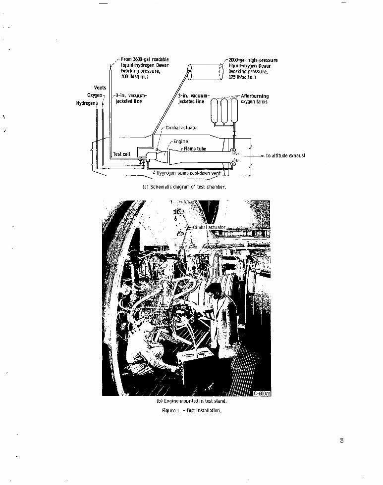
The t e s t s were conducted i n a Lewis a l t i t u d e chamber. A schematic diagram and a photograph of t he t e s t i n s t a l l a t ion a r e p re sen ted i n f i gu re 1. Propel- l a n t s were t ransferred with a conventional cryogenic pressurized system from Dewars located in the storage area through vacuum-jacketed l ines. The f a c i l i t y exhaust system was capable of maintaining the required alt i tude pressures f o r full flow expansion i n the rocket engine nozzle. An afterburner system added a suff ic ient quant i ty of oxygen to the rocke t exhaus t in o rder to burn any residual combustibles t o completion. Data for the required amount of oxidant were obtained from studies reported in reference 3.
The engine used f o r t h e t e s t s was a P r a t t & Whitney RLlOA-3 f l i g h t model ( f i g . l ( b ) ) . A t rated conditions, a chamber pressure of 300 pounds per square inch absolute and a propel lant mixture ra t io of 5.0, th i s engine produced 15 000 pounds of t h r u s t i n a vacuum environment. Details of the engine and components can be found in re fe rences 4 and 5. The engine w a s mounted horizon- t a l l y i n t h e t e s t chamber, and a three-point suspension system, consisting of
2
,rFrom 3600-gal roadable r 2000-gal high-pressure ’ liquid-hydrogen Dewar
(working pressure, liquid-oxygen Dewar
To altitude exhaust
( a ) Schematic diagram of test chamber.
(bl Engine mounted in test stand.
Figure 1. -Test installation.
3

Facil i ty pitch plane (vehic le yaw)
I
retract ion Yaw extension
Faci I i ty -___ +" yaw plane
Yaw retract ion (vehicle pi tch)
I
Figure 2. - Def in i t ion of actuator movements (viewed upstream).
the RLlO gimbal block mount and two gim- bal actuators supplied by t h e Centaur vehicle manufacturer, was used t o support t he engine. Relative ac tua tor movements, as viewed upstream, are defined i n f i g - ure 2. The engine axes, as mounted i n the t es t f a c i l i t y , were rotated 90' t o those of the Centaur vehicle, and the data presented herein are based on the f a c i l i t y mounting. Since the existing thrust s tand was used f o r t h e t e s t s , (
Centaur spring constants were not simu- la ted. <
The Centaur f l i g h t gimbal system, supplied by the vehicle manufacturer, i s a closed loop servocontrol system with i t s main component being the power package assembly and two servocontrolled actuators. The power package contains a miniature constant displacement, vane- type pump, which supplies flow at 1100
~~
pounds per square inch gage pressure to t he ac tua to r s , and - i s d i r ec t ly coupled t o the engine oxygen pump drive. This pump functions only when the engine i s f i r i ng . During fl ight coast periods, a thermostat ical ly control led, e lectr i - cally operated pump circulates the hydraul ic f l u i d through the system. When- ever the temperature in t he hydrau l i c system fal ls below a predetermined value, the c i rcu la t ing pump i s activated, and the ent i re system i s maintained a t a nearly uniform temperature. The c i rcu la t ing pump i s also used f o r slow move- ments p r i o r t o engine start. I n a d d i t i o n t o t h e two vane pumps, t h e power package houses the necessary re l ief and check valves, an accumulator t o dampen output pressure surges, and a reservoi r to p revent cav i ta t ion of t h e main pump. The ac tua tors a re of t r a i l - r o d design t o a l l o w equal force t o be exerted while t h e rod i s re t racted or extended.
A variable-displacement hydraulic pump w a s used during these tes ts to augment the Centaur system i n providing the capabili ty t o hold the engine hor- izonta l and for nonfiring operation. A complete descr ipt ion of t he Centaur hydraulic system can be found in re fe rence 6.
Instrumentation
The engine was instrumented t o monitor and record the engine operating parameters. Included among these were propellant flow rates, engine component i n l e t and out le t pressures and temperatures, combustion-chamber pressure, th rus t , and ambient conditions. Pressure measurements were obtained by the 'u se of strain-gage type transducers, and temperatures were measured by platinum resistance-type sensors (ref. 7) .
Special instrumentation concerned with the gimbal system was a l s o provided.
4

TABLE I. - GIMBAL LNSTRIJMENTMION
Description
Actuator different ia l pressure P i t c h
High pressure Low pressure
High pressure Low pressure
Hydraulic o i l p r e s s u r e Hydraulic o i l temperature 1 Hydraulic o i l temperature 2 Gimbal bearing temperature
Yaw
P i t c h Yaw
Engine position signal (linear potentiometer Posi t ion indicators
Yaw Engine position 1 (64.49 in . )a Engine position 2 (50.42 in . ) Engine position 3 (32.64 in.)
Engine position 1 (64.44 in.) Engine posi t ion 2 (50.38 i n . ) Engine posi t ion 3 (32.59 i n . )
P i t ch
Input signal P i t c h Yaw
P i t ch Yaw
Feedback s igna l
Gimbal angle (gimbal block), Yaw Torsional load
Recorder
D ig i t a l and oscil lograph Oscillograph
D i g i t a l and oscil lograph Oscillograph Oscillograph Dig i t a l D i g i t a l
D ig i t a l D i g i t a l
D ig i t a l and oscil lograph Dig i t a l and oscil lograph Dig i t a l and oscil lograph
Dig i t a l and oscil lograph Dig i t a l and oscil lograph Dig i t a l and oscil lograph
Oscillograph Oscillograph
Oscillograph Dig i t a l and Oscillograph Oscillograph Dig i t a l and oscil lograph
%osi t ion measured a x i a l l y from gimbal pin.
The gimbal instrumentation consisted of hydraulic o i l pressure and temperature, ac tua tor d i f fe ren t ia l p ressures , gimbal system input and feedback signals, and three linear potentiometers each f o r yaw and p i t ch mounted in t he ax ia l p l ane along the thrust chamber and nozzle skirt .
The parameters were recorded on an automatic digital data recorder capable of recording 4000 samples per second and on direct-writ ing oscil lographs located i n t h e f a c i l i t y c o n t r o l room. Transient and frequency response data were ob- tained from the oscil lographs. Measured pressures were not corrected f o r t h e added dynamics of the connecting l ine lengths, whereas e lec t r ica l s igna ls ( input and feedback signals) had no at tenuat ion in the f requency range of i n t e re s t . The gimbal instrumentation and the types of recorder used are l i s t ed i n t a b l e I.
PROCEDURE
Engine Movements
Ehgine posi t ion was controlled by a servoamplifier system supplied by the
5

60-cps signal '\
Actuator hydraulic avity due to amplifier distortion system input signal trace -,
Time - Figure 3. - Copy of typical oscillograph record showing nonlinearity of signal from servoamplifier.
c -
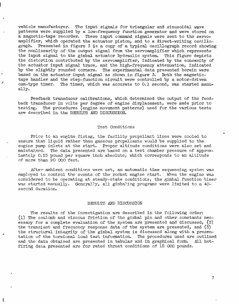
vehicle manufacturer. The input s igna ls for t r iangular and sinusoidal wave pa t te rns were supplied by a low-frequency function generator and were stored on a magnetic-tape recorder. These input command s ignals were s e n t t o t h e servo- amplifier, which operated the actuator piston, and t o a direct-wri t ing osci l lo- graph. Presented i n f igure 3 i s a copy of a typical oscil lograph record showing the nonl inear i ty of the output signal from the servoamplifier which represents t he i npu t s igna l t o t he gimbal actuator hydraulic system. This f igure depicts the dis tor t ion contr ibuted by the servoamplifier, indicated by the concavity of the actuator input s ignal t race, and the high-frequency attenuation, indicated by t h e s l i g h t l y rounded corners. The experimental data presented herein were based on the actuator input s ignal as shown i n f i g u r e 3. Both the magnetic- tape handler and the s tep-funct ion c i rcui t were controlled by a motor-driven cam-type timer. The timer, which was accura te to 0.1 second, was started manu- a l ly .
5
d
Feedback t ransducer cal ibrat ions, which determined the output of t h e feed- back t ransducer in vo l t s per degree of engine displacement, were made p r i o r t o tes t ing . The procedures (engine movement pat terns) used for the var ious tests are descr ibed in the RESULTS p;ND DISCUSSION.
Test Conditions
Pr ior t o an engine f i r ing , the fac i l i ty p rope l lan t l ines were cooled t o . ensure that l iquid rather than gaseous propellants would be supplied t o t h e
engine pump i n l e t s a t the s tar t . Proper a l t i tude condi t ions were a l so set and maintained. The data presented are based on a t e s t chamber pressure of approx- imately 0.25 pound per square inch absolute, which corresponds t o an a l t i t u d e of more than 9 0 000 fee t .
After ambient conditions were set, an automatic time sequencing system w a s employed to cont ro l the events of the rocket engine start. When the engine w a s considered t o be operating a t steady-state conditions, the gimbal function t imer w a s s t a r t ed manually. Generally, a l l gimbaling programs were l i m i t e d t o a 40- second duration.
RESULTS AND DISCUSSION
The r e s u l t s of the investigation are described in the following order: (1) The coulomb and v iscous f r ic t ion of t h e gimbal p in and other constants nec- essary for a complete evaluation of t h e system are presented and discussed, (2) t he t r ans i en t and frequency response data of t h e system are presented, and ( 3 )
> t he s t ruc tu ra l i n t eg r i ty of t h e gimbal system i s discussed along with a presen- t a t i o n of the to rs iona l load t e s t information. The procedures used are outlined and the data obtained are presented in tabular and in g raph ica l form. All hot- f i r i n g data presented are for ra ted thrust condi t ions of 15 000 pounds.
7
Determination of Coulomb and Viscous Friction of Gimbal Pin
A complete analysis of t h e gimbal system requires that constants concerned w5th the ac tua tors and t h e f a c i l i t y b e determined along with the coulomb and V ~ S C O U S f r i c t i o n of t h e gimbal pin. Included are the g rav i ta t iona l e f fec ts of horizontal mounting of the engine, the thrust offset or misalinement vector, t h e test-stand f lex ib i l i ty cons tan t , the ac tua tor in te rna l f r ic t ion , and the fac i l i ty p rope l lan t duc t res t ra in ts . These constants were obtained as a s ide r e s u l t of the coulomb and v iscous f r ic t ion tests or were supplied by the vehicle manufacturer. A summary of t h e r e s u l t s and the procedures used t o o b t a i n them are presented. r
Gravi ta t ional effects . - The gravi ta t iona l e f fec ts due to ho r i zon ta l mounting of the engine were determined by not ing the ac tua tor d i f fe ren t ia l p res - sure required to hold the engine a t the nu l l pos i t i on when the propellant ducts were not connected. In the yaw mode, the vehicle manufacturer considered this e f f e c t t o be negligible or equal t o zero; however, a yaw ac tua to r d i f f e ren t i a l pressure of approximately 11 pounds per square inch (actuator extending) was required t o maintain a nul l posi t ion. Mult ipl icat ion of this value ( in pounds per square foot) by the actuator pis ton area (0.0106 sq f t ) and the actuator .moment am about the gimbal pin (1.16 f t ) yielded a gravi ta t iona l e f fec t moment value. Since the reaction in t he ac tua to r t ended t o extend the actuator (a . posi t ive moment), it can be concluded t h a t t h e yaw mode gravi ta t ional force opposed extension of t h e a c t u a t o r t o y i e l d a negative moment of 19 .5 foot- pounds. The engine offset center of gravity, created by the loca t ion of t h e turbopump package, could possibly have caused this load because the engine would have a tendency to pivot about both the gimbal p in and the p i t ch ac tua to r ground support.
c
I n t h e p i t c h mode, an actuator different ia l pressure of -434 pounds per square inch (actuator retracting) was required t o hold the engine a t t h e n u l l posit ion. Converting this reaction to a moment value about the gimbal pin yielded a gravi ta t iona l e f fec t of 769 foot-pounds (a tendency t o extend the actuator) , which i s i n agreement with the product of the engine weight (includ- ing the hydraulic pump and instrumentation) and the dis tance from the center of mass t o t h e gimbal pin.
The ax ia l loca t ion of the engine center of mass would be dependent on t h e cosine function of the angular displacement. Since the angular displacement was l i m i t e d i n th i s program t o +2O, the axial distance could be considered as constant ; therefore , the gravi ta t ional moment about t he gimbal pin would also be constant. The amount of force required by the ac tua tors t o hold the engine i n a pos i t ion o ther than nu l l w a s found by taking the difference between the ac tua tor d i f fe ren t ia l p ressures a t this pos i t ion and a t the nu l l pos i t ion . Re- <
t rac t ing the ac tua tor from n u l l t o -2' with a s tep input resul ted in an actuator d i f fe ren t ia l p ressure of -464 pounds per square inch, and extending the actuator .from n u l l t o 2O yielded a value of -408 pounds per square inch. In order to.. hold the engine a t -20 ( re t ract ing the actuator) , an addi t ional force of 45.8 pounds was thus required. The addi t ional force was due t o t h e f a c t t h a t t h e actuator moment arm was shortened, as can be seen i n t h e schematic diagram of the p i t ch ac tua to r pos i t i ons i n figure 4. A displacement from n u l l t o 2 O (ex-
8
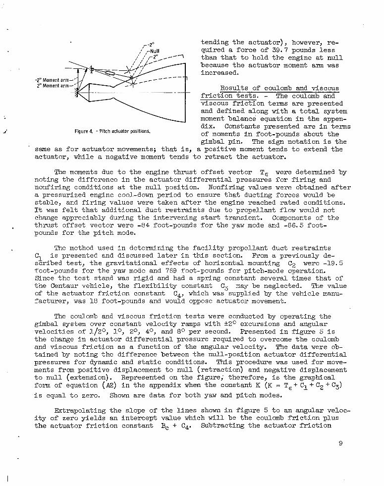
r -2" tending the actuator) , however, re- quired a force of 39.7 pounds less than tha t to ho ld the engine a t n u l l because the actuator moment am was increased.
"""1
Results of coulomb and viscous ".
f r i c t i e s t s . - The coulomb and v iscous f r ic t ion terms are presented and defined along with a t o t a l system moment balance equation i n t h e appen- dix. Constants presented are i n terms of moments i n foot-pounds about t he gimbal pin. The sign notation i s the
Figure 4. - Pitch actuator positions.
same as for actuator movements; t h a t is , a pos i t ive moment tends t o extend the actuator, while a negative moment tends to r e t r ac t t he ac tua to r .
The moments due t o t h e engine thrust offset vector T, were determined by not ing the d i f fe rence in the ac tua tor d i f fe ren t ia l p ressures for f i r i n g and nonfiring conditions a t the null posit ion. Nonfiring values were obtained af ter a pressurized engine cool-down period to ensure that ducting forces would be s table , and f i r ing va lues were taken after the engine reached rated conditions. It was f e l t t ha t add i t iona l duc t r e s t r a in t s due to propel lant f low would not change appreciably during the intervening start transient. Components of t he thrus t o f fse t vec tor were -84 foot-pounds f o r t h e yaw mode and -86.5 foot- pounds f o r t h e p i t c h mode.
The method used i n de te rmining the fac i l i ty p rope l lan t duc t res t ra in ts C1 i s presented and d i scussed l a t e r i n t h i s s ec t ion . From a previously de- s c r ibed t e s t , t he g rav i t a t iona l e f f ec t s of horizontal mounting C2 were -19.5 foot-pounds f o r t h e yaw mode and 769 foot-pounds f o r pitch-mode operation. Since the t e s t s t and w a s r i g id and had a spring constant several t imes that of t he Centaur vehicle, the f lexibil i ty constant Cg may be neglected. The value of the ac tua tor f r ic t ion cons tan t C4, which was supplied by the vehicle manu- facturer , w a s 18 foot-pounds and would oppose actuator movement.
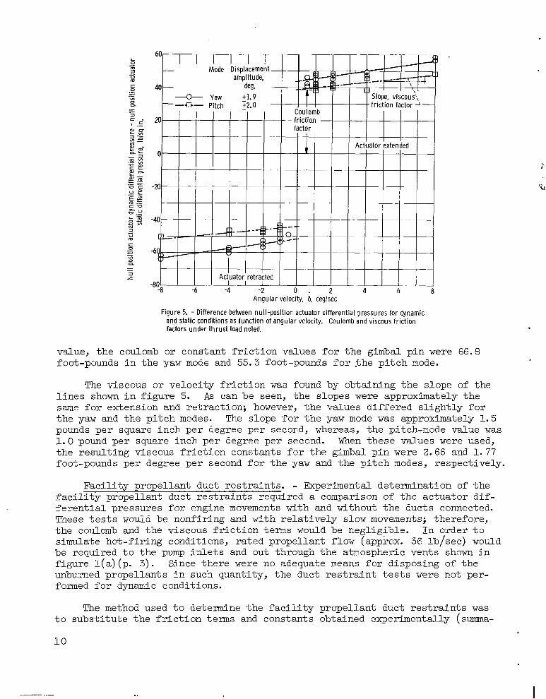
The coulomb and v i scous f r i c t ion t e s t s were conducted by operating the gimbal system over constant velocity ramps with -12O excursions and angular ve loc i t ies of 1 / 2 O , lo, 2O, 4O, and 8 O per second. Presented i n f i g u r e 5 i s t h e change in ac tua to r d i f f e ren t i a l p re s su re r equ i r ed t o overcome t h e coulomb and v iscous f r ic t ion as a function of the angular velocity. The data were ob- tained by not ing the difference between the nu l l -pos i t ion ac tua tor d i f fe ren t ia l pressures for dynamic and s ta t ic condi t ions. This procedure was used f o r move- ments from posi t ive displacement to nul l ( re t ract ion) and negative displacement to nul l (extension) . Represented on the f igure; therefore , i s the graphical form of equation (A2) i n t h e appendix when the constant K ( K = T, + Cl + C2 i- C3) i s equal t o zero. Shown a re data for both yaw and p i t ch modes.
M r a p o l a t i n g the slope of t h e l i n e s shown i n f i g u r e 5 t o an angular veloc- i t y of zero yields an intercept value which wi l l be the coulomb f r i c t ion p lus the ac tua tor f r ic t ion cons tan t B, + Cq. Subtract ing the actuator f r ic t ion
9
-80" 1 1 1 1 1 1 1 -8 -6 -4 -2 0 . 2 4 6
Angular velocity, 6, deglsec
Figure 5. - Difference between nul l-posit ion actuator dif ferential pressures for dynamic and static conditions as funct ion of angular velocity. Coulomb and viscous friction factors under thrust load noted,
1 8
value, the coulomb or constant fr iction values for the gimbal pin were 66.8 foot-pounds i n the yaw mode and 55.3 foot-pounds f o r $he p i t c h mode.
The viscous or ve loc i ty f r i c t ion was found by obtaining the slope of the l i n e s shown i n f i g u r e 5. As can be seen, the slopes were approximately t h e same for extension and retract ion; however, the values differed s l ight ly for t he yaw and the p i t ch modes. The slope for t h e yaw mode was approximately 1.5 pounds per square inch per degree per second, whereas, the pitch-mode value was 1 .0 pound per square inch per degree per second. When these values were used, the resul t ing viscous f r ic t ion constants f o r t he gimbal p in were 2.66 and 1. 77 foot-pounds per degree per second f o r t h e yaw and the p i t ch modes, respectively.
Faci l i ty propel lant duct res t ra ints . - Experimental determination of t h e fac i l i ty p rope l lan t duc t res t ra in ts requi red a comparison of the ac tua tor d i f - ferent ia l pressures for engine movements with and without the ducts connected. These t e s t s would be nonfiring and with relatively slow movements; therefore, t he coulomb and the viscous f r ic t ion terms would be negligible. In order t o simulate hot-firing conditions, rated propellant flow (approx. 36 lb/sec) would be required t o the pump i n l e t s and out through the atmospheric vents shown i n f igure l ( a ) (p. 3). Since there were no adequate means for disposing of t he unburned p rope l l an t s i n such quant i ty , the duct res t ra int tes ts were not per- formed f o r dynamic conditions.
The method used t o de te rmine the fac i l i ty p rope l lan t duc t res t ra in ts was t o s u b s t i t u t e t h e f r i c t i o n terms and constants obtained experimentally ( s m a -
10

TABLE 11. - SUMMARY OF EXPERI3ENTA-L CONSTANTS I N
OF MOMENTS ABOUT GIMBAL PIN
~ - ~
Constant Momentsa about gimbal pin , f t - l b
Retraction Extension Retraction IExtension
P i t ch mode Yaw mode .. .
Coulomb f r i c t i o n , Bc 55.3 -55.3 66.8 -66 -8
Viscous f r i c t i o n , Br b-2.66
-86 -5 -86.5 -84 -0 -84.0 Thrust offset vector, T, 18 .O -18 -0 18 .O -18 -0 Actuator f r ic t ion, C4 0 0 0 0 Flex ib i l i ty cons tan t , C3
769 769 -19 -5 -19.5 Gravi ta t iona l e f fec t , C2 b1 .77 b-l .77 b2 .66
%osi t ive moments tend t o extend actuator; negative moments tend t o
bViscous f r i c t i o n i n t e r m s of f t- lb/(deg/sec).
~ _ _
r e t r ac t ac tua to r .
r i z e d i n t a b l e 11) into equat ion (A2). Resulting values f o r t h e yaw mode were 140 foot-pounds when the ac tua tor was re t racted and 82 foot-pounds when it w a s extended, whereas, f o r t h e p i t c h mode, the duct res t ra int values were 212 and 20 foot-pounds f o r r e t r ac t ion and extension, respectively.
Transient and Frequency Response
As major objectives of the invest igat ion, the t ransient and the frequency response of t he gimbal system were determined. Included are the frequency response parameters (gain and phase lag) , the damping charac te r i s t ic of t h e gimbal system, and the evaluation of t imes for 63.2 and 90 percent of change f o r a step input.
Frequency response of gimbal system. - Tests to determine the frequency response of t h e gimbal system were conducted by operating the engine over si- nusoidal wave input frequencies of 114, 112, 1, 2, 4, and 8 cps. Nominal
amplitude variations included k- , *io, *lo, and 12 for the yaw mode and +1/8O and -11/2O fo r t he p i t ch mode.
lo 10 8
The hot-firing frequency response parameters for the various amplitudes are presented for both operating modes i n f i g u r e 6. Shown on the f igure as a function of f requency are the ra t ios of engine angular position 6 measured a t
the phase lag between these variables. Examination of t h e data shows t h a t , f o r both operating modes, the frequency response of t h e gimbal system was re la t ive- l y f l a t to about 0.5 cps. A trend i s noted toward greater attenuations with increasing displacements, which i s typ ica l fo r systems such as this; however, the spread i s s l igh t .
r t he gimbal pin (feedback transducer) t o the input demand angular posit ion and
Presented i n f i g u r e 7 a r e the r a t i o s of the engine angular posit ion meas-
11

-150
-200 '0 W m
W- - m m c
2 c m a
Or
0
-10
-20
-30
fl m c3 .-
Frequency, cps
(b) Pi tch mode.
Figure 6. - Hot-firing gimbal system frequency response parame- ters.
(a) Yaw mode.
10
0
-1 u u m , 2 . 4 .6 .8 1 2 4 6 8 1 0
Frequency, cps
(b) Pitch mode.
Figure 7. - Cornoarison of engine position measured at nozzle exit and at gimbal pin for yaw and pitch modes.
ured a t the nozz le ex i t to the en- gine angular posit ion at the gimbal pin for both operat ing modes. These data are included to show tha t f lex- ing of the engine occurred as it was driven a t the higher frequencies. Examination of the figure yields t h a t , i n t h e yaw mode, the engine began t o f l e x a t approximately 1.5 cps, whereas, t he p i t ch mode, f lex- ing began a t about 0 . 7 cps.
These frequency response data were obtained with the existing fa- c i l i t y t h r u s t s t a n d and engine mounts, which had a spring constant several times t h a t of the Centaur vehicle; thus, corrections to the data are necessary f o r application d
t o s o f t e r mounts.
Transient response of the gimbal system. - Determination of the tran- sient response and damping charac- t e r i s t i c s of the gimbal system were included in t he i nves t iga t ion . These
12

''6O-cps signal
f f
1 in.
I I
,r Engine posit ion
Feedbacpn;;,7 II
,,~
of change Input s i nal-. -
Step input /
in i t ia t ion J' Time for
of change 90 Percent of change
-~ ~
-- 90 percent of change
-Feedback signal " ..
- _c
~~ ''.Input signal Time -D
Figure 8. - Copy of typical hot-fir ing transient response oscil lograph trace showing gimbal move- ment from null position to -1" (actuator retracted) in yaw mode. Calibration: input signal, 0.695 degree per inch; feedback signal, 0.695 degree per inch; engine positions, 1.0 degree per inch.
TPBLF rrr. - G I M E I ~ SYSTEM RESPONSE TIMES
I Response time, sec, for -
6 3 . 2 percent of change of change 90 percent
-~ ~ ~~ l R e t r y t i o n l M e n s t o n Retraction1 Extension
Yaw mode
Fir ing .198 .198 .m3 .093 Nonfiring
0.194 0.19 4 0. 093 0. 093
~
t Pitch mode
Fir ing .167 .273 .085 .135 Nonf i r i n g
0.167 0.258 0. 080 0.131
determinations were obtained by operating the system with step inputs of +1/4O, '1/2O, and +lo displacement about the null posi- t ion .
Examination of the feedback s ignal t race, shown i n a copy of a typical osci l lograph record pre- sented i n f i g u r e 8, shows t h a t t h e gimbal system response w a s nonos- c i l l a t o r y and general ly s imilar to an overdamped second-order system. Response times for the system may be measured, fo r a s tep input , as time t o 63.2 and 90 percent of change as noted i n figure 8. Since the response times for the range
of displacements tested were within a 0.02-second band, average values f o r the various operating modes are presented in table 111.
-
A s can be seen from t he da t a p re sen ted i n t ab l e 111, t h e yaw mode response t imes for f i r ing and nonfiring compared favorably. The difference between t h e p i t ch mode response t imes for retracting the actuator (up) and extending the actuator (down) was caused by the g rav i ta t iona l e f fec t o f mounting the engine
13
horizontal ly . No appreciable difference was noted i n t h e yaw mode response times f o r f i r i n g and nonfiring when r e t r ac t ing or extending; however, one can be seen for the p i tch mode response times f o r f i r i n g and nonfiring when r e t r a c t - ing the actuator . The response time for f i r i n g i s less than that for nonfir ing, which can be explained by the direct ion of the thrust offset or misalinement vector, which has. components, viewed upstream, t h a t are up and t o t h e r i g h t . The v e r t i c a l component of t h i s fo rce t ends t o he lp upward movements and r e t a rd downward movements. The values of the thrust offset vector components are l i s t e d i n t a b l e I1 (p. 11).
Demonstration of Structural Integrity of Gimbal System
One of the major objectives of the investigation reported herein was t o demonstrate the structural integrity of the engine and the actuators under dynamic stresses. Presented throughout this report are data obtained from a var ie ty of t e s t s des igned t o meet t h i s ob jec t ive . Among these was the evalu- ation of factors concerned with the torsional loads on the gimbal pins created by the off-center locat ion of the center of mass of the engine. These fac tors were determined f o r slow movements, s t ep changes, and for cycling operation.
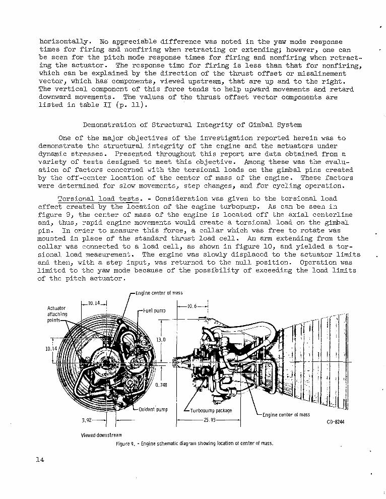
Torsional load tests. - Consideration was g iven to the to rs iona l load effect created by the l oca t ion of the engine turbopump. A s can be seen i n f igure 9, the center of mass of the engine i s located off the axial center l ine and, thus, rapid engine movements would create a tors iona l load on the gimbal p in . In o rder to measure th i s fo rce , a co l l a r which was free t o r o t a t e was mounted in p l ace of the s tandard thrust load c e l l . An arm extending from the co l l a r was connected t o a load ce l l , as shown i n f i g u r e 10, and yielded a to r - sional load measurement. The engine was s lowly displaced to the actuator limits . and then, with a s tep input , was returned to the nu l l pos i t ion . Opera t ion was l i m i t e d t o t h e yaw mode because of the possibility of exceeding the load limits of the p i tch ac tua tor .
L 1 0 . 1 4 J / ,-Engine center of mass
I L T u r b o p u m p package
I- CD-8244
Viewed downstream Figure 9. - Engine schematic diagram showing location ot center Of mass.
14

Load cell-, /
\
4 \ f i
Positive Negative moment moment
F igure 10. -Torsional load measurement apparatus (viewed upstream).
0.1 sec -60-cps signal - , "~ . ~"
Torsional load due to slow movement to
Torsional load ,I
cel l null position>
actuator l imi t LTorsional load cel l
,Input signal
, \ \ 'LFeedback signal \ \
'LEngine posit ion (l inear potentiometer)
'--Step signal init iation
\ ." . ~ .
,-Engine position null .. .
\ ,-Feedback signal null
'-Input signal null
Time - . ..~ ~ ~ ~"
(a) Step change from posit ive l imit (actuator extended) to null.
F igure 11. -Typical hot-f ir ing osci l lograph record showing torsional load cel l response to Step change. Calibrat ion torsional load, 125 foot-pounds per inch; input signal, 0.667 degree per inch; feedback signal, 0.671 degree per inch; engine position, 1.0 degree per inch.
15

I I
~ ~ _ _ 0.1 sec
~ -
,-6O-cps signal
I ~-
,-Torsional load cel l
rFeedback signal null
Enqine position
Feedback signal7
Step signal i n i t i a t i o n l ' ' I
Time - ~~ ~ ~ . __
(b) Step change from negative limit (actuator retracted) to nu l l .
Figure 11. - Concluded.
When the engine was slowly displaced from the nu l l pos i t ion to the ac tua-
2- , a dynamic to r s iona l l oad , i n add i t ion t o one created lo) 2
by the offset center of gravi ty of the engine, was noticed at the gimbal block. This load can be seen on the copies of typical oscillograph records presented i n f i g u r e 11 jus t p r io r to the point of s tep s ignal ini t ia t ion. The additional to rs iona l e f fec t can be explained by the fact that the engine does not move la te ra l ly bu t p ivots about the p i tch ac tua tor ground support and thus creates a tors iona l moment. When the actuator was extended t o i t s l i m i t , an average addi t ional tors ional moment of 155 foot-pounds clockwise (viewed upstream) r e - sulted, whereas, the actuator was retracted, the average additional moment value was found t o b e 130 foot-pounds counterclockwise.
16
The engine was then returned to t he nu l l pos i t i on w i th a s tep input s ignal . A s can be seen i n figure 11, the tors ional load created by displacing the en- g ine to the ac tua tor limits was returned t o i t s null value without an overshoot; however, a slight r inging occurred, which amounted t o approximately k7.5 foot- pounds. These da t a i nd ica t e t ha t no appreciable dynamic tors iona l e f fec t w i l l be created by step movements of the engine from the actuator limits t o t h e n u l l posi t ion.
.
Additional dynamic tors ional effects during cycl ing operat ion were a l so determined. The system was operated sinusoidally Tn the yaw mode over frequen- cies ranging from 1 t o 4 cps with an input signal amplitude of +1/2'. Because of the frequency response of the system, the actual angular displacement varied from kO.44O t o +0.24O at 1 and 4 cps, respectively. The r a t i o of the tors ional moment to the angular displacement, however, appeared t o be constant, with an average value of 77 foot-pounds per degree, which indicated that the moment value was not a function of the operating frequency. For the amplitude range invest igated, the addi t ional tors ional moment due to cycl ic operat ion could therefore be considered as a linear function of the angular displacement.
-. - - .a
!
Additional demonstrations of structural integrity of the gimbal system. - Described throughout t h i s r e p o r t a r e a var ie ty of tes ts designed to demonstrate
~
t he s t ruc tu ra l i n t eg r i ty of t h e gimbal system-under thrust load. Many of these tests exceeded the loads and requirements of the system as def ined for actual flight conditions in unpublished data supplied by the vehicle manufacturer. One such example would be the frequency response tests. During these tests,
, the system w a s operated sinusoidally over frequencies from 1/4 t o 8 cps with
amplitude variations ranging from 5- t o 5 1 ~ for the yaw mode and +- and k- 8 8 2
, i n p i t c h . The maximum angular ve loc i t ies t es ted were therefore 480 per second i n yaw and 16O per second i n p i t c h , whereas the system requirements c a l l f o r maximum angular velocities of 5O and 8 O per second fo r yaw and pitch, respec- t i ve ly . The system was thus concluded t o be sound and would meet the vehicle fl ight requirements.
10 10 10 10
Throughout t h e t e s t program, the gimbal system, which includes the engine, the hydraulic system, and the actuators , endured without any hardware f a i l u r e s . The s t ruc tu ra l i n t eg r i ty of t h e system was thus demonstrated by the various tes t s descr ibed wi th in th i s repor t .
SUMMARY OF RESULTS
An invest igat ion was conducted t o determine the response characterist ics of a Centaur gimbal system. The data presented are based on t h e f a c i l i t y mounting of the engine. The actuator planes were rotated about the engine
plane corresponds to the vehic le p i tch p lane , and the f ac i l i t y p i t ch p l ane corresponds t o t h e v e h i c l e yaw plane. A posi t ive moment value indicates a tendency t o extend the actuator, whereas a negative moment t e n d s t o r e t r a c t t h e actuator .
I! axial center l ine 900 t o t h a t of t he Centaur vehicle; that is, t h e f a c i l i t y yaw
1. The g rav i t a t iona l e f f ec t s due to ho r i zon ta l mounting of the engine were determined. These e f f ec t s are normally considered t o be negligible or equal
* 1 7
t o zero for yaw-mode operation; however, a moment of 19.5 foot-pounds was re- quired to hold the engine in the nul l posi t ion. In the pi tch mode, a moment f
about the gimbal pin of 769 foot-pounds was needed t o hold the engine at the nul1 posit ion. A s t e p change from n u l l t o -2O (actuator re t racted) required an additional force of 45.8 pounds, while a movement from n u l l t o 2O (actuator extended) required a force of 39.7 pounds l e s s t h a n t h a t t o hold the engine at the nu l l pos i t ion .
2. The thrust offset vector coordinates for the engine used for t h e t e s t s were determined. Moment values about the gimbal pin were -84 foot-pounds fo r t h e yaw plane and -86.5 foot-pounds for the p i tch p lane .
3. Coulomb and viscous friction values of the ginibal pins were determined. The coulomb or constant-friction values were 66.8 foot-pounds fo r t he yaw mode and 55.3 foot-pounds f o r t h e p i t c h mode. The viscous or veloc i ty- f r ic t ion values were 2.66 and 1 . 7 7 foot-pounds per degree per second for the yaw and t h e p i t c h modes, respectively.
4. The f ac i l i t y p rope l l an t duc t r e s t r a in t s were found for ac tua tor re t rac- t i o n and extension for both yaw and p i t ch modes. I n t h e yaw mode, t he r e su l t - ing duct res t ra int moments were 140 foot-pounds fo r r e t r ac t ion and 82 foot- pounds for extension. The p i t ch mode values were 212 and 20 foot-pounds for r e t r ac t ion and extension, respectively.
5. The frequency response of the system was f la t t o 0.5 cps for both yaw and p i t ch modes with a t rend for greater a t tenuat ions with increasing angular displacements. Flexing of the engine was noted at approximately 1.5 cps for yaw-mode operation and at about 0.7 cps i n p i t c h .
6 . The gimbal system was nonoscil latory and generally similar t o an over- damped second-order system.
7 . System response times for a s tep input were found for both 63.2 and 90 percent of change i n b o t h yaw and p i tch modes. I n t h e yaw mode, for hot- firing conditions, the response time for 63.2 percent of change was 0.093 sec- ond, while the t ime for 90 percent of change was 0.194 second. The hot - f i r ing response times i n t h e p i t c h mode varied, depending on whether the ac tua tor was extended or retracted. For actuator extension, the response times were C.080 second f o r 63.2 percent of change and 0.167 second f o r 90 percent of change, whereas for retraction, the response time values were 0.131 second and 0.258 second for 63.2 and 90 percent of change, respect ively.
8. When the engine was slowly displaced from t h e n u l l p o s i t i o n i n t h e yaw mode, a tors iona l moment, i n add i t ion to one created by the locat ion of t he engine center of mass, was observed. The addi t ional moment values ranged from c 155 foot-pounds for actuator extension to 130 foot-pounds for retraction.
9. A s tep change from the actuator limits (approx. k2L0) t o t h e n u l l p o s i - 2
t i o n produced a s l igh t r i ng ing i n t he t o r s iona l l oad ce l l , amounting t o k7.5 foot-pounds, without an overshoot.
18

10. The to r s iona l moment effect of sinusoidal cycling of the system could t be considered as a linear function of the angular displacement. Resulting
ra t ios o f the to rs iona l moment t o t h e angular displacement appeared t o b e a constant of approximately 77 foot-pounds per degree.
11. The s t ruc tura l in tegr i ty o f the gimbal system under t h r u s t w a s demon- s t r a t e d i n t h e v a r i o u s t e s t s performed and described herein.
Lewis Research Center, National Aeronautics and Space Administration,
Cleveland, Ohio, October 6, 1965.
19
I
APPENDM - DEFINITION O F COULOMB AND VISCOUS F R I C T I O N TEXMS
The method of calculat ing the coulomb Bc and viscous Br f r ic t ion va lues r
are defined as follows:
A b i a x i a l summation of the total system moments about the gimbal pin for the nul l posi t ion yields the fol lowing equat ion:
where
A
R
@P
I r
d .. 6
57.3
B r
BC
T €
C1
c2
c3
c4
1, ij' m m = - + B r 6 + B c y f T , * C1 +_ C2 * C3 - + c4 6
57.3 l6 1
actuator pis ton area, sq f t
actuator moment arm, f t
ac tua to r d i f f e ren t i a l p re s su re , l b / sq f t
engine mass moment of iner t ia , s lug-sq f t
angular velocity, deg/sec
angular acceleration, deg/sec
conversion constant , deg/rad
v iscous f r ic t ion , f t - lb / ( deg/sec)
coulomb f r i c t i o n , f t - l b
th rus t o f f se t vec to r , f t - l b
duct r e s t r a i n t s , f t - l b
g rav i t a t iona l e f f ec t s , f t - l b
f l e x i b i l i t y c o n s t a n t , f t - l b
ac tua to r i n t e rna l f r i c t ion , f t - l b
2
If the angular veloci ty 6 i s constant, equal zero; the inertial term would thus equation ( A l ) becomes
the angular accelerat ion 6 would ..
be eliminated. If K = T, + C1 f C2 f C3,
which i s the equat ion for a s t r a i g h t l i n e i n i n t e r c e p t form. Presented i n f i g - ure 12 is equation ( A 2 ) for extension and r e t r ac t ion of t he gimbal system actu-
20

?
I
S
K
Bc + c 4
l 0
y A R A P = B r 6 + B c - + K + C f, where Br=- dAR AP) la1 - - 4p d b '.
Angular velocity, 6, deglsec
Figure 12. - Graphical presentation of equation (A2) for extension and retraction of gimbal system actuators.
a to r s . When the angular veloci ty F i s equal t o zero, the coulomb o r constant f r i c t i o n E, can be defined as the average differential pressure intercept minus K 4- Cq. The viscous o r v e l o c i t y f r i c t i o n Br can be defined as the average slope of the l ines for ex tens ion and r e t r ac t ion .
Equations ( A l ) and ( A 2 ) as shown are p rec ise for the n u l l posi t ion; how- ever, other terms should be added i f they are to be used f o r any other angular pos i t ion . Such terms as the torque a t t h e gimbal pin and a t the ac tua tor mounts would have t o be included, because the engine does not move l a t e r a l l y (yaw) or ve r t i ca l ly (p i t ch ) bu t p ivo t s on the ac tua tor ground supports.
21

~FEREN!ES
1. Wanhainen, John P.; Antl, Robert J.; Hannum, Ned P.; and Mansour, Ali H.: Throt t l ing Character is t ics of a Hydrogen-Oxygen, Regeneratively Cooled, Pump-Fed Rocket Engine. NASA TM X-1043, 1964.
2 . Conrad, E . William.; Hannum, Ned P .; and Bloomer, Harry E. : Photographic Study of Liquid-Oxygen Boiling and Gas I n j e c t i o n i n t h e I n j e c t o r of a Chug- ging Rocket Engine. NASA TM X-948, 1964.
3. Bloomer, Harry E.; Renas, Paul E.; and Antl, Robert J.: Experimental Inves- t i g a t i o n i n an Alti tude Test Facil i ty of Burning of Excess Combustibles i n a Rocket Engine Exhaust. NASA TN D-ZOO, 1960.
4. Anon.: RLlOA-3 Liquid Rocket Engines Service Manual. P r a t t & Whitney Aircraf t , Aug. 15, 1962.
6 . Davis, Howard D. : The Centaur Hydraulic System. Paper Presented at Vickers Aerospace Fluid Power Conf., Detroit (Mich.), Apr. 29-30, 1962 .
7 . Ladd, John W. : A Durable and Reliable Test Stand System for High-Accuracy Temperature Measurements i n t h e Cryogenic Ranges of Liquid Hydrogen and v
Liquid Oxygen. Vol. V I of Advances i n Cryogenic Eng., K . D . Timerhaus, ed., Plenum Press, 1961, pp. 388-395.
r;
2 2 L
NASA-Langley, 1966 E-2921