steady and unsteady aerodynamics - wit press · steady and unsteady aerodynamics m.f. platzer &...
TRANSCRIPT

Steady and unsteady aerodynamics
M.F. Platzer & K.D. JonesAeroHydro Research & Technology Associates, Pebble Beach, CA, USA.
Abstract
This paper discusses the major flow features encountered by conventional airfoils in low-speedflows. To this end, steady flow over a NACA 0012 airfoil at zero, moderate, and near-stall incidenceangles is described. This is followed by a discussion of the unsteady flow phenomena caused bysudden changes in airfoil incidence angle or by airfoil oscillation.
1 Introduction
In the first paper of this volume [1] the fundamentals of lift and drag generation were presentedand it was shown that lift is linked to vortex generation and drag is critically dependent on thestate of the flow (i.e. attached or separated) and on the state of the boundary layer (i.e. laminar orturbulent). It is instructive to study the changes in flow features in response to various parameterchanges, such as changes in incidence angle and Reynolds number. To keep the discussion inbounds, we limit ourselves to two-dimensional incompressible flows, i.e. to low-speed airfoilflows. To this end, we consider only one representative airfoil shape and choose the NACA 0012airfoil. Nevertheless, even with this restriction, very different flow phenomena are obtained. Onehas to distinguish between attached flow at zero or moderate incidence angle, flow close to andbeyond flow separation, flow due to rapid incidence change without flow separation, flow due torapid incidence change with flow separation and flow due to airfoil oscillation. All these flows aredependent on the chosen Reynolds number. These cases are therefore discussed separately in thefollowing sections.
2 Steady low-speed airfoil flow at zero or moderate incidence angle
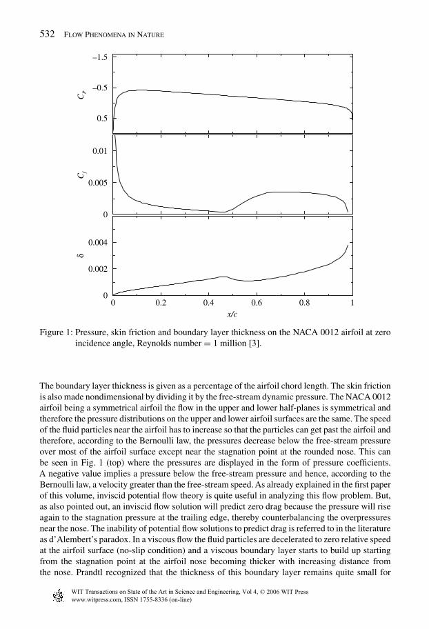
In Fig. 1 we show the pressure, boundary layer thickness and skin friction distributions causedby an incompressible flow of Reynolds number 1 million over the NACA 0012 airfoil at zeroincidence angle. The pressures are indicated as pressure differences relative to the free-streampressure and are made nondimensional by dividing them by the free-stream dynamic pressure.
www.witpress.com, ISSN 1755-8336 (on-line)
© 2006 WIT PressWIT Transactions on State of the Art in Science and Engineering, Vol 4,
doi:10.2495/1-84564-095-0/6a
532 Flow Phenomena in Nature
–1.5
–0.5
0.5
CP
0
0.005
0.01
Cf
0 0.2 0.4 0.6 0.8 1x/c
0
0.002
0.004
δ
Figure 1: Pressure, skin friction and boundary layer thickness on the NACA 0012 airfoil at zeroincidence angle, Reynolds number = 1 million [3].
The boundary layer thickness is given as a percentage of the airfoil chord length. The skin frictionis also made nondimensional by dividing it by the free-stream dynamic pressure. The NACA 0012airfoil being a symmetrical airfoil the flow in the upper and lower half-planes is symmetrical andtherefore the pressure distributions on the upper and lower airfoil surfaces are the same. The speedof the fluid particles near the airfoil has to increase so that the particles can get past the airfoil andtherefore, according to the Bernoulli law, the pressures decrease below the free-stream pressureover most of the airfoil surface except near the stagnation point at the rounded nose. This canbe seen in Fig. 1 (top) where the pressures are displayed in the form of pressure coefficients.A negative value implies a pressure below the free-stream pressure and hence, according to theBernoulli law, a velocity greater than the free-stream speed. As already explained in the first paperof this volume, inviscid potential flow theory is quite useful in analyzing this flow problem. But,as also pointed out, an inviscid flow solution will predict zero drag because the pressure will riseagain to the stagnation pressure at the trailing edge, thereby counterbalancing the overpressuresnear the nose. The inability of potential flow solutions to predict drag is referred to in the literatureas d’Alembert’s paradox. In a viscous flow the fluid particles are decelerated to zero relative speedat the airfoil surface (no-slip condition) and a viscous boundary layer starts to build up startingfrom the stagnation point at the airfoil nose becoming thicker with increasing distance fromthe nose. Prandtl recognized that the thickness of this boundary layer remains quite small for
www.witpress.com, ISSN 1755-8336 (on-line)
© 2006 WIT PressWIT Transactions on State of the Art in Science and Engineering, Vol 4,
Steady and Unsteady Aerodynamics 533
flows of sufficiently large Reynolds number. In most aeronautical engineering applications theReynolds number (based on the airfoil chord) is at least several hundred thousand or, more often,several million. In such cases Prandtl’s approach [2] to split the analysis into two steps worksquite well, i.e. obtain the pressure distribution by means of a potential flow analysis because thepressure changes very little within the boundary layer at a given airfoil station and then performthe boundary layer analysis using the previously determined pressure distribution as input. Theresults obtained by such an approach, using the computer programs documented in reference [3],are shown in Fig. 1 (middle), where the skin friction is plotted, and in Fig. 1 (bottom), where theboundary layer thickness distribution is shown. The boundary layer flow starts out as a laminarflow near the nose because the flow velocities are small. It remains laminar as long as the flowis accelerating, i.e. as long as the pressures are falling. However, the flow in the boundary layerbecomes turbulent soon after the fluid particles enter a region of increasing (i.e. adverse) pressuregradient and finally the flow starts to separate very near the trailing edge. As a consequence, afinite drag is generated because of the friction effect caused by the laminar and turbulent boundarylayers (skin friction drag) and because of the separated flow region near the trailing edge (pressuredrag). Note that the transition to turbulent flow manifests itself by a marked increase in skin frictionand it occurs downstream of the point of maximum airfoil thickness. These predictions are foundto agree quite well with measurements of the pressure, boundary layer thickness and skin frictiondistributions.
In Fig. 2 we show the same information, in addition to the results obtained after setting theairfoil to an incidence angle of 4◦. It is immediately evident that the upper surface pressuresare significantly lower at 4◦ than at 0◦, especially near the leading edge, whereas the pressureson the lower surface are substantially higher than the zero incidence pressures. Hence suctionis generated on the upper surface, with a distinct suction peak near the leading edge. There-fore, the upper surface is often referred to as suction surface and the lower surface as pressuresurface. The pressure difference between the pressure and suction surfaces adds up to a finitelift. Note that the largest pressure differences occur over the forward half of the airfoil. There-fore, the resultant lift acts at or near the quarter chord point. The pressures on the lower surfaceare greater than the free-stream pressure and this airfoil surface is therefore called the pres-sure surface. As mentioned in the first paper of this volume, Newton hypothesized that the liftis generated by overpressure on the lower surface due to the impact of the fluid particles onthe lower surface. However, as can be seen from the pressure distributions shown in Fig. 2,the suction effect on the upper surface contributes more to the resultant lift than the overpres-sure on the lower surface. The skin frictions and boundary layer thicknesses shown in Fig. 2(middle and bottom) reveal that on the suction surface the boundary layer transition has movedupstream close to the leading edge because the adverse pressure gradient region starts close tothe leading edge. Of particular importance is the fact that the transition to turbulent flow pre-vents the onset of flow separation near the leading edge. Again, as already mentioned in thefirst paper of this volume, a laminar boundary layer is much less resistant to flow separationthan a turbulent one. This fact manifests itself by the behavior of the laminar skin friction. It isseen that the laminar skin friction drops rapidly toward a zero value, which is indicative of theonset of flow separation. Fortunately, the flow becomes turbulent before then and the onset ofairfoil stall is prevented. As in the case of laminar versus turbulent flow over the sphere, dis-cussed in the first paper of this volume, the transition to turbulent flow is quite beneficial in thiscase. As a matter of fact, flight at lower Reynolds numbers is much trickier because there is agreater tendency toward flow separation. These phenomena have become of increasing interestand importance with the development of small unmanned air vehicles and especially of micro airvehicles.
www.witpress.com, ISSN 1755-8336 (on-line)
© 2006 WIT PressWIT Transactions on State of the Art in Science and Engineering, Vol 4,

534 Flow Phenomena in Nature
5.1−
5.0−
5.0
CP
0
500.0
10.0
Cf
18.06.04.02.00c/x
0
200.0
400.0
δ
0 degrees, both surfaces4 degrees, lower surfaces4 degrees, upper surfaces
Figure 2: Comparison of the aerodynamic characteristics of the NACA 0012 airfoil at 0◦ and 4◦incidence angle, Reynolds number = 1 million [3].
3 Low-speed airfoil flow near the stall angle
A further increase of the incidence angle inevitably leads to the onset of flow separation which isinitially limited to a small region near the leading edge where the fluid particles first encounter anadverse pressure gradient. The fluid particles reverse flow direction only to be swept downstreamagain by the neighboring particles farther away from the airfoil surface. As a consequence, aso-called leading-edge separation bubble is formed near the leading edge which contains recir-culatory flow. A bubble of this type is shown in Fig. 3, based on an interferogram taken byM.S. Chandrasekhara [4], visualizing the flow over a NACA 0012 airfoil at an incidence angle of10◦ in a flow of Reynolds number 540,000.
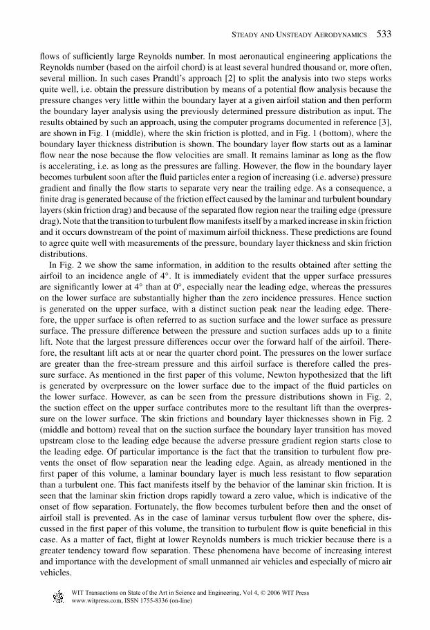
A progressive increase in the incidence enlarges the separation bubble until the flow breaksaway quite massively at an incidence angle of 11.95◦, as shown in Fig. 4. This is the condition ofairfoil stall. The suction that contributed the major part of the lift at the lower incidence anglescannot be maintained any longer, causing a large loss in lift. This is shown in Fig. 5 for the NACA0012 airfoil, taken from reference [5] which contains measured lift and pitching moment coeffi-cient (about the quarter-chord point) data on many airfoils. Note the effect of Reynolds number.
www.witpress.com, ISSN 1755-8336 (on-line)
© 2006 WIT PressWIT Transactions on State of the Art in Science and Engineering, Vol 4,

Steady and Unsteady Aerodynamics 535
Figure 3: Development of a leading-edge separation bubble [4].
Figure 4: Leading-edge stall on the NACA 0012 airfoil [4].
The stall angle increases with increasing Reynolds number. Also note that the inviscid flow theory(solid line) cannot predict the onset of stall. Furthermore, it is also important to note that the flowceases to remain steady as soon as the stall angle is exceeded. The large wake flow generated bythe flow separation near the leading edge becomes a fluctuating three-dimensional flow.
The onset of stall and the resulting loss of lift depend on the airfoil geometry. Thin airfoilstend to generate leading-edge stall of the type described above for the NACA 0012 airfoil. On theother hand, on thick airfoils the flow separation typically starts from the trailing edge. As a result,the loss in lift is much more benign. Readers interested in further details can refer to the work byAbbott and von Doenhoff [5] and Eppler [6].
4 The Wagner effect
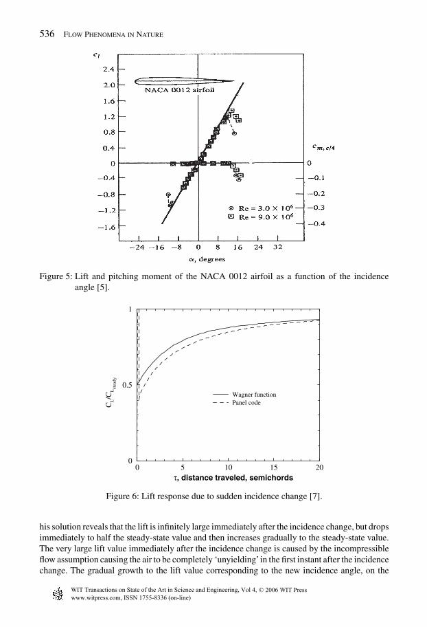
As already pointed out in the first paper of this volume, the physics of lift generation becomesmuch more understandable by considering the vortex shedding process from the airfoil’s trailingedge in response to a sudden incidence change. Herbert Wagner [7] was the first to provide amathematical solution to this problem in 1925. Using the linearized inviscid incompressible flowtheory he derived the lift response plotted in Fig. 6. It shows that the lift builds up only graduallyto the steady-state value after a sudden small change in the incidence angle. A closer inspection of
www.witpress.com, ISSN 1755-8336 (on-line)
© 2006 WIT PressWIT Transactions on State of the Art in Science and Engineering, Vol 4,
536 Flow Phenomena in Nature
Figure 5: Lift and pitching moment of the NACA 0012 airfoil as a function of the incidenceangle [5].
0 5 10 15 20τ, distance traveled, semichords
0
0.5
1
CL
C/L
Wagner functionPanel code
stea
dy
Figure 6: Lift response due to sudden incidence change [7].
his solution reveals that the lift is infinitely large immediately after the incidence change, but dropsimmediately to half the steady-state value and then increases gradually to the steady-state value.The very large lift value immediately after the incidence change is caused by the incompressibleflow assumption causing the air to be completely ‘unyielding’ in the first instant after the incidencechange. The gradual growth to the lift value corresponding to the new incidence angle, on the
www.witpress.com, ISSN 1755-8336 (on-line)
© 2006 WIT PressWIT Transactions on State of the Art in Science and Engineering, Vol 4,
Steady and Unsteady Aerodynamics 537
other hand, is caused by the shedding of the starting vortex. This counterclockwise vortex has astrong influence on the velocity and pressure field around the airfoil as long as it remains in closeproximity. As can be seen from Fig. 6, the airfoil travels about 20 half-chord lengths until the liftreaches about 95% of the final value. Another way of explaining the Wagner effect is to say that itis caused by the fluid’s ‘memory’. Vortices shed at an earlier time are being ‘remembered’becausethey are being carried downstream only with a finite velocity. Wagner obtained his solution foran infinitely thin flat plate. The panel code solution differs somewhat from this solution becauseit is obtained for a finite thickness airfoil.
5 The Kramer effect
In 1932 Max Kramer [8] performed wind tunnel experiments that were stimulated by the obser-vations of some pilots that ‘gusty air was better than calm air’ as far as lift was concerned. Rapidchanges in the incidence angle appeared to generate inexplicably high lift values, in clear con-tradiction to the Wagner effect. He therefore conceived an experiment which allowed him tosimulate a sudden vertical gust in the wind tunnel and which confirmed the pilot observations.Rapid incidence angle changes produced lift values that exceeded the corresponding steady-statevalues. The effect was measured to be directly proportional to the rate of incidence angle change.Kramer postulated that the most probable explanation for this effect was the inertia of the flowseparation process.
In the ensuing years this dynamic lift or stall effect has been studied in considerable detail, bothexperimentally and computationally, because of its importance in the operation of flight vehiclesand wind turbines. For example, helicopter blades may fail due to exposure to dynamic stall. Onthe other hand, fighter aircraft designers have tried to take advantage of dynamic lift to improvefighter maneuverability.
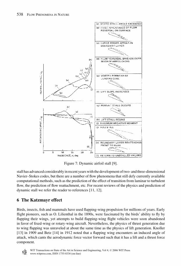
The fundamental difference between the static and dynamic airfoil stall phenomena is shownin Fig. 7 which is based on low-speed wind tunnel measurements by Carr et al. [9]. As alreadyfound by Kramer, an airfoil that is pitched rapidly through the static stall angle produces a liftmuch greater than the maximum observed at a steady angle of attack. Due to the delay in pressurebuildup, similar to the delay responsible for the Wagner effect, the boundary layer separation isdelayed on the suction surface and the lift continues to increase past the maximum static lift.Eventually, flow reversal occurs in the boundary layer which is followed by the development ofa clockwise vortex near the leading edge. This vortex keeps growing and moving over the upperairfoil surface, thereby inducing low pressures on this surface. As a result, a substantially largerpressure difference between the lower and upper surfaces, and therefore a larger lift, is inducedthan would be possible under static conditions. Therefore, for a short period of time lift valuesthat can be twice the static values are produced. However, this beneficial effect is lost as soon asthe dynamic stall vortex approaches the trailing edge. As seen in Fig. 7, the lift decreases abruptlywhile, at the same time, a sharp pitching moment spike is induced. As the airfoil incidence isreduced, the fully stalled flow over the suction surface starts to reattach. Hence the flow behaviorduring the pitch-up and pitch-down strokes is quite different, leading to the hysteresis loops shownin Fig. 7. This is further illustrated in Fig. 8 showing the suction surface pressure distributionsmeasured by McAlister et al. [10] on a NACA 0012 airfoil which is oscillated with an amplitude of10◦ around a fixed angle of 15◦. Note the very large suction peaks near the leading edge followedby an abrupt collapse of the leading edge suction.
These dynamic stall features can vary significantly, depending on airfoil shape, free-streamReynolds number and Mach number, and flow three-dimensionality. The prediction of dynamic
www.witpress.com, ISSN 1755-8336 (on-line)
© 2006 WIT PressWIT Transactions on State of the Art in Science and Engineering, Vol 4,
538 Flow Phenomena in Nature
Figure 7: Dynamic airfoil stall [9].
stall has advanced considerably in recent years with the development of two- and three-dimensionalNavier–Stokes codes, but there are a number of flow phenomena that still defy currently availablecomputational methods, such as the prediction of the effect of transition from laminar to turbulentflow, the prediction of flow reattachment, etc. For recent reviews of the physics and prediction ofdynamic stall we refer the reader to references [11, 12].
6 The Katzmayr effect
Birds, insects, fish and mammals have used flapping-wing propulsion for millions of years. Earlyflight pioneers, such as O. Lilienthal in the 1890s, were fascinated by the birds’ ability to fly byflapping their wings, yet attempts to build flapping-wing flight vehicles were soon abandonedin favor of fixed-wing or rotary-wing aircraft. Nevertheless, the physics of thrust generation dueto wing flapping was unraveled at about the same time as the physics of lift generation. Knoller[13] in 1909 and Betz [14] in 1912 noted that a flapping wing encounters an induced angle ofattack, which cants the aerodynamic force vector forward such that it has a lift and a thrust forcecomponent.
www.witpress.com, ISSN 1755-8336 (on-line)
© 2006 WIT PressWIT Transactions on State of the Art in Science and Engineering, Vol 4,
Steady and Unsteady Aerodynamics 539
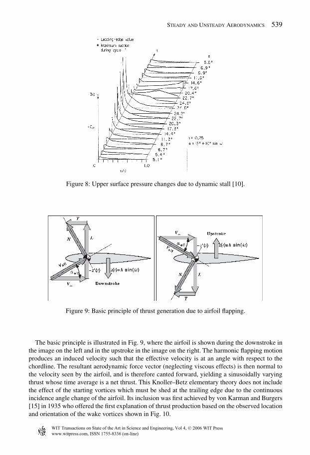
Figure 8: Upper surface pressure changes due to dynamic stall [10].
Figure 9: Basic principle of thrust generation due to airfoil flapping.
The basic principle is illustrated in Fig. 9, where the airfoil is shown during the downstroke inthe image on the left and in the upstroke in the image on the right. The harmonic flapping motionproduces an induced velocity such that the effective velocity is at an angle with respect to thechordline. The resultant aerodynamic force vector (neglecting viscous effects) is then normal tothe velocity seen by the airfoil, and is therefore canted forward, yielding a sinusoidally varyingthrust whose time average is a net thrust. This Knoller–Betz elementary theory does not includethe effect of the starting vortices which must be shed at the trailing edge due to the continuousincidence angle change of the airfoil. Its inclusion was first achieved by von Karman and Burgers[15] in 1935 who offered the first explanation of thrust production based on the observed locationand orientation of the wake vortices shown in Fig. 10.
www.witpress.com, ISSN 1755-8336 (on-line)
© 2006 WIT PressWIT Transactions on State of the Art in Science and Engineering, Vol 4,

540 Flow Phenomena in Nature
Figure 10: Vortex street behind a harmonically plunging airfoil [16].
However, in 1922, Katzmayr [17] had already provided the first experimental verification ofthe Knoller–Betz theory. He chose to oscillate the flow rather than the airfoil, recognizing theapproximate equivalence of both arrangements. His measurements indeed yielded a net thrustacting on the airfoil.
The basic physics of the thrust generation due to airfoil flapping becomes clear by looking atFig. 10. The largest changes in positive or negative incidence angle occur when the airfoil movesthrough the top or bottom positions, respectively. Therefore, during one cycle the airfoil shedscounterclockwise vorticity as it passes through the top position, followed by clockwise vorticityas it passes through the bottom position. As a result, a vortex street is being generated downstreamof the airfoil, which induces a velocity increase between the two rows. The sinusoidally plungingairfoil therefore acts like a conventional propeller that captures a certain amount of fluid and givesit an increased time-averaged velocity. Measurements of the time-averaged velocity downstreamof the trailing edge indeed yield a jet-like velocity profile [18]. Hence the flapping airfoil becomesa ‘jet engine’ that propels the bird forward by ejecting a certain amount of fluid in the oppositedirection.
References
[1] Platzer, M.F. & Jones, K.D., Concepts of aero- and hydromechanics. Flow Phenomena inNature, Vol. 1, pp. 5–19, 2006.
[2] Prandtl, L., Ueber Fluessigkeitsbewegung bei sehr kleiner Reibung. Verhandlungen des IIIInternat. Math. Kongr., Heidelberg, 8–13 August 1904, Teubner: Leipzig, pp. 484–491,1905.
[3] Cebeci, T., Platzer, M.F., Chen, H., Chang, K.C. & Shao, J.P., Analysis of Low-SpeedUnsteady Airfoil Flows, Springer: Berlin, 2005.
www.witpress.com, ISSN 1755-8336 (on-line)
© 2006 WIT PressWIT Transactions on State of the Art in Science and Engineering, Vol 4,

Steady and Unsteady Aerodynamics 541
[4] Carr, L.W., Chandrasekhara, M.S. & Brock, N., A quantitative study of unsteady compress-ible flow on an oscillating airfoil. Journal of Aircraft, 31(4), pp. 892–898, 1994.
[5] Abbott, I.H. & von Doenhoff, A.E., Theory of Wing Sections, Dover Publications:New York, 1959.
[6] Eppler, R., Airfoil Design and Data, Springer-Verlag: Berlin, Heidelberg, NewYork, 1990.[7] Wagner, H., Ueber die Entstehung des dynamischenAuftriebes von Tragfluegeln. Zeitschrift
für Angewandte Mathematik und Mechanik, 5(1), 1925.[8] Kramer, M., Die Zunahme des Maximalauftriebes von Tragfluegeln bei ploetzlicher
Anstellwinkelvergroesserung. Zeitschrift für Flugtechnik und Motorluftschiffahrt, 23(7),pp. 185–189, 1932.
[9] Carr, L.W., McAlister, K.W. & McCroskey, W.J., Analysis of the development of dynamicstall based on oscillating airfoil experiments, NAS TN D-8382, 1977.
[10] McAlister, K.W., Carr, L.W. & McCroskey, W.J., Dynamic stall experiments on the NACA0012 airfoil, NASA TP-1100, 1978.
[11] Ekaterinaris, J.A., Chandrasekhara, M.S. & Platzer, M.F., Recent developments in dynamicstall measurements, computations and control, AIAA Paper No. 2005-1296, January 2005.
[12] Ekaterinaris, J.A. & Platzer, M.F., Computational prediction of airfoil dynamic stall.Progress in Aerospace Science, 33, pp. 759–846, 1997.
[13] Knoller, R., Die Gesetze des Luftwiderstandes. Flug- und Motortechnik (Wien), 3(21),pp. 1–7, 1909.
[14] Betz, A., Ein Beitrag zur Erklaerung des Segelfluges. Zeitschrift fuer Flugtechnik undMotorluftschiffahrt, 3, pp. 269–272, 1912.
[15] von Karman,T. & Burgers, J.M., General aerodynamic theory—perfect fluids.AerodynamicTheory, Vol. II, ed. W.F. Durand, Julius Springer: Berlin, p. 308, 1934.
[16] Jones, K.D., Lund, T.C. & Platzer, M.F., Experimental and computational investigation offlapping wing propulsion for micro air vehicles (Chapter 16). Progress in Astronautics andAeronautics, Vol. 195, American Institute of Aeronautics and Astronautics, 2001.
[17] Katzmayr, R., Effect of periodic changes of angle of attack on behavior of airfoils. NACATM 147, October 1922.
[18] Lai, J.C.S. & Platzer, M.F., Jet characteristics of a plunging airfoil. AIAA Journal, 37(12),pp. 1529–1537, 1999.
www.witpress.com, ISSN 1755-8336 (on-line)
© 2006 WIT PressWIT Transactions on State of the Art in Science and Engineering, Vol 4,